EP1063485A1 - Appareil et procédé de séparation d'air par distillation cryogénique - Google Patents
Appareil et procédé de séparation d'air par distillation cryogénique Download PDFInfo
- Publication number
- EP1063485A1 EP1063485A1 EP00401768A EP00401768A EP1063485A1 EP 1063485 A1 EP1063485 A1 EP 1063485A1 EP 00401768 A EP00401768 A EP 00401768A EP 00401768 A EP00401768 A EP 00401768A EP 1063485 A1 EP1063485 A1 EP 1063485A1
- Authority
- EP
- European Patent Office
- Prior art keywords
- column
- low pressure
- air
- condenser
- pressure column
- Prior art date
- Legal status (The legal status is an assumption and is not a legal conclusion. Google has not performed a legal analysis and makes no representation as to the accuracy of the status listed.)
- Granted
Links
- 238000000926 separation method Methods 0.000 title claims abstract description 14
- 238000004821 distillation Methods 0.000 title claims description 15
- 238000000034 method Methods 0.000 title claims description 14
- 239000007788 liquid Substances 0.000 claims abstract description 56
- IJGRMHOSHXDMSA-UHFFFAOYSA-N Atomic nitrogen Chemical compound N#N IJGRMHOSHXDMSA-UHFFFAOYSA-N 0.000 claims abstract description 45
- QVGXLLKOCUKJST-UHFFFAOYSA-N atomic oxygen Chemical compound [O] QVGXLLKOCUKJST-UHFFFAOYSA-N 0.000 claims abstract description 39
- 239000001301 oxygen Substances 0.000 claims abstract description 39
- 229910052760 oxygen Inorganic materials 0.000 claims abstract description 39
- 229910052757 nitrogen Inorganic materials 0.000 claims abstract description 21
- 238000002156 mixing Methods 0.000 claims abstract description 15
- 239000007789 gas Substances 0.000 claims abstract description 14
- 239000012530 fluid Substances 0.000 claims description 16
- 238000004519 manufacturing process Methods 0.000 claims description 5
- 238000010586 diagram Methods 0.000 description 10
- 239000000203 mixture Substances 0.000 description 5
- 239000006200 vaporizer Substances 0.000 description 5
- MYMOFIZGZYHOMD-UHFFFAOYSA-N Dioxygen Chemical compound O=O MYMOFIZGZYHOMD-UHFFFAOYSA-N 0.000 description 3
- 238000001816 cooling Methods 0.000 description 3
- 238000010992 reflux Methods 0.000 description 3
- XKRFYHLGVUSROY-UHFFFAOYSA-N Argon Chemical compound [Ar] XKRFYHLGVUSROY-UHFFFAOYSA-N 0.000 description 2
- 238000007664 blowing Methods 0.000 description 2
- 229910001873 dinitrogen Inorganic materials 0.000 description 2
- 238000004887 air purification Methods 0.000 description 1
- 229910052786 argon Inorganic materials 0.000 description 1
- 238000012512 characterization method Methods 0.000 description 1
- 230000006835 compression Effects 0.000 description 1
- 238000007906 compression Methods 0.000 description 1
- 230000000694 effects Effects 0.000 description 1
- 238000000605 extraction Methods 0.000 description 1
- 238000000227 grinding Methods 0.000 description 1
- 238000002347 injection Methods 0.000 description 1
- 239000007924 injection Substances 0.000 description 1
- 238000011084 recovery Methods 0.000 description 1
- 238000005057 refrigeration Methods 0.000 description 1
- 230000002040 relaxant effect Effects 0.000 description 1
- 239000002699 waste material Substances 0.000 description 1
Images

Classifications
-
- F—MECHANICAL ENGINEERING; LIGHTING; HEATING; WEAPONS; BLASTING
- F25—REFRIGERATION OR COOLING; COMBINED HEATING AND REFRIGERATION SYSTEMS; HEAT PUMP SYSTEMS; MANUFACTURE OR STORAGE OF ICE; LIQUEFACTION SOLIDIFICATION OF GASES
- F25J—LIQUEFACTION, SOLIDIFICATION OR SEPARATION OF GASES OR GASEOUS OR LIQUEFIED GASEOUS MIXTURES BY PRESSURE AND COLD TREATMENT OR BY BRINGING THEM INTO THE SUPERCRITICAL STATE
- F25J3/00—Processes or apparatus for separating the constituents of gaseous or liquefied gaseous mixtures involving the use of liquefaction or solidification
- F25J3/02—Processes or apparatus for separating the constituents of gaseous or liquefied gaseous mixtures involving the use of liquefaction or solidification by rectification, i.e. by continuous interchange of heat and material between a vapour stream and a liquid stream
- F25J3/04—Processes or apparatus for separating the constituents of gaseous or liquefied gaseous mixtures involving the use of liquefaction or solidification by rectification, i.e. by continuous interchange of heat and material between a vapour stream and a liquid stream for air
- F25J3/04763—Start-up or control of the process; Details of the apparatus used
- F25J3/04866—Construction and layout of air fractionation equipments, e.g. valves, machines
- F25J3/04872—Vertical layout of cold equipments within in the cold box, e.g. columns, heat exchangers etc.
- F25J3/04878—Side by side arrangement of multiple vessels in a main column system, wherein the vessels are normally mounted one upon the other or forming different sections of the same column
-
- F—MECHANICAL ENGINEERING; LIGHTING; HEATING; WEAPONS; BLASTING
- F25—REFRIGERATION OR COOLING; COMBINED HEATING AND REFRIGERATION SYSTEMS; HEAT PUMP SYSTEMS; MANUFACTURE OR STORAGE OF ICE; LIQUEFACTION SOLIDIFICATION OF GASES
- F25J—LIQUEFACTION, SOLIDIFICATION OR SEPARATION OF GASES OR GASEOUS OR LIQUEFIED GASEOUS MIXTURES BY PRESSURE AND COLD TREATMENT OR BY BRINGING THEM INTO THE SUPERCRITICAL STATE
- F25J3/00—Processes or apparatus for separating the constituents of gaseous or liquefied gaseous mixtures involving the use of liquefaction or solidification
- F25J3/02—Processes or apparatus for separating the constituents of gaseous or liquefied gaseous mixtures involving the use of liquefaction or solidification by rectification, i.e. by continuous interchange of heat and material between a vapour stream and a liquid stream
- F25J3/04—Processes or apparatus for separating the constituents of gaseous or liquefied gaseous mixtures involving the use of liquefaction or solidification by rectification, i.e. by continuous interchange of heat and material between a vapour stream and a liquid stream for air
- F25J3/04248—Generation of cold for compensating heat leaks or liquid production, e.g. by Joule-Thompson expansion
- F25J3/04284—Generation of cold for compensating heat leaks or liquid production, e.g. by Joule-Thompson expansion using internal refrigeration by open-loop gas work expansion, e.g. of intermediate or oxygen enriched (waste-)streams
- F25J3/0429—Generation of cold for compensating heat leaks or liquid production, e.g. by Joule-Thompson expansion using internal refrigeration by open-loop gas work expansion, e.g. of intermediate or oxygen enriched (waste-)streams of feed air, e.g. used as waste or product air or expanded into an auxiliary column
- F25J3/04303—Lachmann expansion, i.e. expanded into oxygen producing or low pressure column
-
- F—MECHANICAL ENGINEERING; LIGHTING; HEATING; WEAPONS; BLASTING
- F25—REFRIGERATION OR COOLING; COMBINED HEATING AND REFRIGERATION SYSTEMS; HEAT PUMP SYSTEMS; MANUFACTURE OR STORAGE OF ICE; LIQUEFACTION SOLIDIFICATION OF GASES
- F25J—LIQUEFACTION, SOLIDIFICATION OR SEPARATION OF GASES OR GASEOUS OR LIQUEFIED GASEOUS MIXTURES BY PRESSURE AND COLD TREATMENT OR BY BRINGING THEM INTO THE SUPERCRITICAL STATE
- F25J3/00—Processes or apparatus for separating the constituents of gaseous or liquefied gaseous mixtures involving the use of liquefaction or solidification
- F25J3/02—Processes or apparatus for separating the constituents of gaseous or liquefied gaseous mixtures involving the use of liquefaction or solidification by rectification, i.e. by continuous interchange of heat and material between a vapour stream and a liquid stream
- F25J3/04—Processes or apparatus for separating the constituents of gaseous or liquefied gaseous mixtures involving the use of liquefaction or solidification by rectification, i.e. by continuous interchange of heat and material between a vapour stream and a liquid stream for air
- F25J3/0446—Processes or apparatus for separating the constituents of gaseous or liquefied gaseous mixtures involving the use of liquefaction or solidification by rectification, i.e. by continuous interchange of heat and material between a vapour stream and a liquid stream for air using the heat generated by mixing two different phases
- F25J3/04466—Processes or apparatus for separating the constituents of gaseous or liquefied gaseous mixtures involving the use of liquefaction or solidification by rectification, i.e. by continuous interchange of heat and material between a vapour stream and a liquid stream for air using the heat generated by mixing two different phases for producing oxygen as a mixing column overhead gas by mixing gaseous air feed and liquid oxygen
-
- F—MECHANICAL ENGINEERING; LIGHTING; HEATING; WEAPONS; BLASTING
- F25—REFRIGERATION OR COOLING; COMBINED HEATING AND REFRIGERATION SYSTEMS; HEAT PUMP SYSTEMS; MANUFACTURE OR STORAGE OF ICE; LIQUEFACTION SOLIDIFICATION OF GASES
- F25J—LIQUEFACTION, SOLIDIFICATION OR SEPARATION OF GASES OR GASEOUS OR LIQUEFIED GASEOUS MIXTURES BY PRESSURE AND COLD TREATMENT OR BY BRINGING THEM INTO THE SUPERCRITICAL STATE
- F25J2200/00—Processes or apparatus using separation by rectification
- F25J2200/04—Processes or apparatus using separation by rectification in a dual pressure main column system
- F25J2200/06—Processes or apparatus using separation by rectification in a dual pressure main column system in a classical double column flow-sheet, i.e. with thermal coupling by a main reboiler-condenser in the bottom of low pressure respectively top of high pressure column
-
- F—MECHANICAL ENGINEERING; LIGHTING; HEATING; WEAPONS; BLASTING
- F25—REFRIGERATION OR COOLING; COMBINED HEATING AND REFRIGERATION SYSTEMS; HEAT PUMP SYSTEMS; MANUFACTURE OR STORAGE OF ICE; LIQUEFACTION SOLIDIFICATION OF GASES
- F25J—LIQUEFACTION, SOLIDIFICATION OR SEPARATION OF GASES OR GASEOUS OR LIQUEFIED GASEOUS MIXTURES BY PRESSURE AND COLD TREATMENT OR BY BRINGING THEM INTO THE SUPERCRITICAL STATE
- F25J2235/00—Processes or apparatus involving steps for increasing the pressure or for conveying of liquid process streams
- F25J2235/50—Processes or apparatus involving steps for increasing the pressure or for conveying of liquid process streams the fluid being oxygen
-
- F—MECHANICAL ENGINEERING; LIGHTING; HEATING; WEAPONS; BLASTING
- F25—REFRIGERATION OR COOLING; COMBINED HEATING AND REFRIGERATION SYSTEMS; HEAT PUMP SYSTEMS; MANUFACTURE OR STORAGE OF ICE; LIQUEFACTION SOLIDIFICATION OF GASES
- F25J—LIQUEFACTION, SOLIDIFICATION OR SEPARATION OF GASES OR GASEOUS OR LIQUEFIED GASEOUS MIXTURES BY PRESSURE AND COLD TREATMENT OR BY BRINGING THEM INTO THE SUPERCRITICAL STATE
- F25J2250/00—Details related to the use of reboiler-condensers
- F25J2250/30—External or auxiliary boiler-condenser in general, e.g. without a specified fluid or one fluid is not a primary air component or an intermediate fluid
- F25J2250/40—One fluid being air
-
- F—MECHANICAL ENGINEERING; LIGHTING; HEATING; WEAPONS; BLASTING
- F25—REFRIGERATION OR COOLING; COMBINED HEATING AND REFRIGERATION SYSTEMS; HEAT PUMP SYSTEMS; MANUFACTURE OR STORAGE OF ICE; LIQUEFACTION SOLIDIFICATION OF GASES
- F25J—LIQUEFACTION, SOLIDIFICATION OR SEPARATION OF GASES OR GASEOUS OR LIQUEFIED GASEOUS MIXTURES BY PRESSURE AND COLD TREATMENT OR BY BRINGING THEM INTO THE SUPERCRITICAL STATE
- F25J2250/00—Details related to the use of reboiler-condensers
- F25J2250/30—External or auxiliary boiler-condenser in general, e.g. without a specified fluid or one fluid is not a primary air component or an intermediate fluid
- F25J2250/52—One fluid being oxygen enriched compared to air, e.g. "crude oxygen"
Definitions
- the invention proposed here relates to the field of gas distillation air and in particular an apparatus and proceeds with air separation by cryogenic distillation. It improves the extraction yield of oxygen and thus the energy performance on the diagrams of distillation not ordinarily comprising a supply of liquefied air into columns and whose refrigeration is ensured by air expansion (oil brake turbine, generator or self-boosted).
- the gains from this invention when installed on an air separation unit are of 3.5% (see case presented below) in oxygen separation energy.
- the basic distillation processes on which the invention can be used are processes which do not ordinarily involve feeding liquid air in the distillation columns.
- These basic processes are processes for the separation of gases from air with air compression, pre-cooling of compressed air, air purification, air cooling in a main exchanger, air separation in a distillation column comprising at least one medium pressure column and a low pressure column and sub-cooling of the liquids coming in reflux from the medium pressure column to the low pressure column.
- Double column (single cycle) producing low oxygen cold box outlet pressure.
- EP-A-0381319 describes a column system in which an air flow vaporizes against a flow containing 95 vol.% oxygen.
- US-A-5765396 relates to a conventional pump process in which a air flow condenses against liquid containing between 98 and 100 mol.%.
- US-A-5582035 and US-A-5291737 disclose separation methods air with mixing column in which all the air enters the columns in gaseous form.
- US-A-3754406 proposes to vaporize rich liquid from the column medium pressure of a double column against nitrogen gas medium pressure. Air is liquefied by heat exchange with liquid oxygen pumped and sent to the low pressure column.
- an air separation device comprising a column system comprising at least one double column comprising a medium pressure column and a low pressure column thermally connected to each other by a first vaporizer-condenser where condenses the head gas of the medium pressure column, means for send compressed and purified air to a heat exchanger where it cools, means for sending cooled air to the medium pressure column under gaseous form, means for sending an oxygen-enriched fluid from the medium pressure column to the low pressure column, where it separates by cryogenic distillation, means for sending a nitrogen-enriched fluid the medium pressure column to the low pressure column, means for withdraw a nitrogen-rich fluid and an oxygen-rich fluid from the column low pressure, a second vaporizer-condenser, means for send air to the second vaporizer-condenser where it condenses at least partially and means for sending air at least partially condensed at the low pressure column, means for sending a liquid the low pressure column or the liquid medium pressure column or a other column from the column system to the
- the at least partially condensed air sent to the low pressure column is the only liquefied air flow sent to the system columns.
- the apparatus comprises means for relaxing the air with production of work before sending it to the second vaporizer-condenser and / or means to cool the air to its dew point before sending it to the second vaporizer-condenser.
- the liquid sent to the second vaporizer-condenser comes from the medium pressure column, from the tank or from a place located at most five theoretical plates above the tank thereof.
- At least partially condensed air can be sent to the column low pressure and / or to the medium pressure column and / or to another column of the column system.
- the apparatus comprises a column of mixture supplied at the head with an oxygen-rich liquid from the lower column pressure and supplied to the tank by a more volatile gas than the liquid rich in oxygen.
- the liquid vaporizes in the second vaporizer-condenser and the apparatus may include means for sending the liquid vaporized at the low pressure column at a level below the first level.
- the low pressure column does not have an overhead condenser.
- a separation process air by cryogenic distillation in an apparatus comprising at least one double column with medium pressure column and low column pressure thermally connected to each other by a first vaporizer-condenser, in which we send a flow of purified, compressed and cooled air to the medium pressure column in gaseous form, an enriched fluid is sent oxygen from the medium pressure column to the low pressure column where it is separated by cryogenic distillation, a nitrogen-enriched fluid is sent from the medium pressure column to the low pressure column, a fluid is drawn off rich in oxygen and a nitrogen rich fluid from the low pressure column, we sends a second flow of purified, compressed and cooled air to a second vaporizer-condenser where it condenses at least partially by exchange heat with a liquid from the medium pressure column or the low pressure column or another column in the column system we sends at least partially condensed air to the low pressure column characterized in that the liquid sent to the second vaporizer-condenser contains between 22 and 70 mol% of oxygen
- Gaseous air from a turbine can be condensed in the second vaporizer / condenser against part of the rich liquid leaving PM or an oxygen-rich liquid, taken from an area of the column BP.
- This fraction of the latter vaporizes at BP pressure and is then introduced in BP in a section under the supply of rich liquid main.
- Liquefied air is introduced, for example, into the LP at a intermediate section between the rich liquid and the lean liquid. (see diagrams attached).
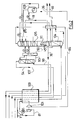
- Figure 1 is a diagram of an apparatus according to the prior art
- Figure 2 is a diagram of an apparatus according to the invention.
- an air flow of 5.25 bar is split in half to form a flow 2 of 188 135 Nm3 / h and a flow 81 of 12900 Nm3 / h.
- Flow 2 is cools in exchanger 100 and is sent to the tank of the middle column pressure 104.
- the flow 81 is boosted to 8.7 bars, partially cooled in the exchanger 100 and expanded in the insufflation turbine 103 before being sent in low pressure column 105.
- the medium pressure column 104 operates at 5 bars and the low column pressure 105 operates at 1.3 bar.
- the columns are thermally connected by a first condenser vaporizer 111.
- the device produces liquid oxygen 46 and liquid nitrogen 36.
- the rich liquid from the medium pressure column 104 is sent to the column low pressure 105 above the supply air level.
- Liquid oxygen 50 drawn from the bottom of the low pressure column is sent to the top of the mixing column 107 after being pumped to 5.1 bars.
- a third air flow 90 cools completely in the exchanger 100 and feeds the mixing column to the tank.
- a tank liquid 93 and optionally at least one intermediate liquid withdrawn from the column of mixture are sent to the low pressure column while an oxygen flow containing 54 to 95 mol% of oxygen is withdrawn at the top of the mixing column and heats up in exchanger 100 with 3100 Nm3 / h of average nitrogen pressure and the low pressure residual.
- the rich liquid 18 sent to the second vaporizer-condenser 109 constitutes 37% of the total flow of rich liquid and vaporizes in this one to then be sent to the low pressure column some theoretical plates above the first vaporizer-condenser 111.
- the apparatus may include an argon column or a pressure column intermediate between medium and low pressures.
- the frigories necessary for the appliance can be produced by a Claude turbine or a nitrogen turbine or by a combination of several turbines.
- the low pressure column can contain at least two vaporizers condensers, the tank vaporizer being supplied for example with nitrogen compressed.
- the mixing column can operate at equal, higher or below average pressure.
- a liquid from the device and rich in nitrogen or oxygen can be pressurized, for example by a pump, and vaporized in the exchanger 100 or another exchanger, for example by exchanging heat with air for provide a gaseous product under pressure.
- the low pressure column can operate at a pressure between 1.5 and 10 bars.
- the lower column pressure operates at between 4 and 10 bars.
- Part of the air from the blowing turbine can be sent to the mixing column.
- Medium and low pressure columns can be built side by side side.
- the process can allow the production of gaseous oxygen by withdrawing a flow of gaseous oxygen in the bottom of the low pressure column.
- the gas is heats up in exchanger 100 and can optionally be compressed once warmed up.
Landscapes
- Engineering & Computer Science (AREA)
- Physics & Mathematics (AREA)
- Mechanical Engineering (AREA)
- Thermal Sciences (AREA)
- General Engineering & Computer Science (AREA)
- Separation By Low-Temperature Treatments (AREA)
Abstract
Description
- on détend le deuxième débit dans une turbine avant d'en envoyer au moins une partie au deuxième vaporiseur-condenseur ;
- on envoie un liquide riche en oxygène de la colonne basse pression en tête d'une colonne de mélange et on envoie un gaz plus volatil que le liquide en cuve de la colonne de mélange, par exemple de l'air ;
- on soutire de l'azote en tête de la colonne moyenne pression ;
- le liquide envoyé au deuxième vaporiseur-condenseur peut provenir d'une/de la colonne de mélange
| Schéma de base Figure 1 | Ajout du condenseur 109 (Figure 2) | |
| Débit d'air (Nm3 /h) | 274700 | 274700 |
| Débit O2 (Nm3/h) | 60000 | 60000 |
| PuretéO2 (rendement 99 %) | 95 mol.% | 95 mol.% |
| Pression O2 (bars abs) | 5 | 5 |
| Débit NGMP 30 (Nm3/h) | 3100 | 11400 |
| Débit NGMP/débit d'air (%) | 1.1 | 4.1 |
| Gain Energie | + 3.5 % |
Claims (17)
- Appareil de séparation d'air comprenant un système de colonnes comprenant au moins une double colonne comprenant une colonne moyenne pression (104) et une colonne basse pression (105) reliées thermiquement entre elles par un premier vaporiseur-condenseur (111) où se condense le gaz de tête de la colonne moyenne pression, des moyens pour envoyer de l'air comprimé et épuré à un échangeur de chaleur (100) où il se refroidit, des moyens (2) pour envoyer de l'air refroidi à la colonne moyenne pression sous forme gazeuse, des moyens pour envoyer un fluide enrichi en oxygène de la colonne moyenne pression à la colonne basse pression où il se sépare par distillation cryogénique, des moyens pour envoyer un fluide enrichi en azote de la colonne moyenne pression à la colonne basse pression, des moyens pour soutirer un fluide riche en azote et un fluide riche en oxygène de la colonne basse pression, un deuxième vaporiseur-condenseur (109), des moyens (86) pour envoyer de l'air au deuxième vaporiseur-condenseur où il se condense au moins partiellement et des moyens pour envoyer l'air au moins partiellement condensé à la colonne basse pression, des moyens (18) pour envoyer un liquide de la colonne basse pression ou de la colonne moyenne pression ou d'une autre colonne (107) du système de colonnes au deuxième vaporiseur-condenseur caractérisé en ce que le liquide (18) envoyé au deuxième vaporiseur-condenseur contient entre 22 et 70 mol.% d'oxygène et en ce que l'air au moins partiellement condensé envoyé au système de colonnes comprend le seul débit d'air liquéfié envoyé au système de colonnes.
- Appareil selon la revendication 1 dans lequel que l'air au moins partiellement condensé envoyé à la colonne basse pression (105) comprend le seul débit d'air liquéfié envoyé au système de colonnes.
- Appareil selon l'une des revendications 1 et 2 comprenant des moyens (103) pour détendre l'air avec production de travail avant de l'envoyer au deuxième vaporiseur-condenseur (109).
- Appareil selon l'une des revendications précédentes comprenant des moyens pour refroidir l'air à son point de rosée avant de l'envoyer au deuxième vaporiseur-condenseur (109).
- Appareil selon l'une des revendications précédentes comprenant une colonne de mélange (107) alimentée en tête par un liquide riche en oxygène (50) provenant de la colonne basse pression et alimentée en cuve par un gaz (90) plus volatil que le liquide riche en oxygène.
- Appareil selon l'une des revendications précédentes comprenant des moyens pour envoyer une partie du liquide de cuve de la colonne moyenne pression (104) directement à la colonne basse pression (105) à un premier niveau et une autre partie (18) du liquide de cuve de la colonne moyenne pression au deuxième vaporiseur-condenseur (109).
- Appareil selon la revendication 6 dans lequel le liquide de cuve se vaporise dans le deuxième vaporiseur-condenseur (109) et comprenant des moyens pour envoyer le liquide vaporisé à la colonne basse pression à un niveau inférieur au premier niveau.
- Appareil selon l'une des revendications précédentes comprenant des moyens (30) pour soutirer un gaz riche en azote en tête de la colonne moyenne pression.
- Appareil selon l'une des revendications précédentes dans lequel la colonne basse pression n'a pas de condenseur de tête.
- Procédé de séparation d'air par distillation cryogénique dans un appareil comprenant au moins une double colonne avec une colonne moyenne pression (104) et une colonne basse pression (105) reliées thermiquement entre elles par un premier vaporiseur-condenseur (111), dans lequel on envoie un débit d'air (2) épuré, comprimé et refroidi à la colonne moyenne pression, sous forme gazeuse, on envoie un fluide enrichi en oxygène de la colonne moyenne pression à la colonne basse pression, où il se sépare par distillation cryogénique, on envoie un fluide enrichi en azote de la colonne moyenne pression à la colonne basse pression, on soutire un fluide riche en oxygène et un fluide en riche azote de la colonne basse pression, on envoie un deuxième débit d'air (86) épuré, comprimé et refroidi à un deuxième vaporiseur-condenseur (109) où il se condense au moins partiellement par échange de chaleur avec un liquide (18) provenant de la colonne moyenne pression et/ou de la colonne basse pression et/ou d'une autre colonne (107) du système de colonnes, on envoie l'air au moins partiellement condensé à la colonne basse pression caractérisé en ce que le liquide (18) envoyé au deuxième vaporiseur-condenseur contient entre 22 et 70 mol.% d'oxygène, éventuellement entre 22 et 35 mol.% d'oxygène, et l'air liquéfié dans le deuxième vaporiseur-condenseur constitue le seul débit d'air liquéfié envoyé au système de colonnes.
- Procédé selon la revendication 10 dans lequel on détend le deuxième débit dans une turbine (103) avant d'en envoyer au moins une partie au deuxième vaporiseur-condenseur (109).
- Procédé selon la revendication 10 ou 11 dans lequel on envoie un liquide riche en oxygène (50) de la colonne basse pression en tête d'une colonne de mélange (109) et on envoie un gaz (90) plus volatil que le liquide en cuve de la colonne de mélange (107).
- Procédé selon la revendication 10, 11 ou 12 dans lequel on soutire de l'azote (30) en tête de la colonne moyenne pression (104), éventuellement sous forme gazeuse.
- Procédé selon l'une des revendications 10 à 13 dans lequel on soutire un liquide et/ou un gaz riche en oxygène en cuve de la colonne basse pression, éventuellement en tant que produit(s).
- Procédé selon l'une des revendications 10 à 14 dans lequel la colonne basse pression opère à entre 1,5 et 10 bar abs, éventuellement entre 3 et 10 bar abs.
- Procédé selon l'une des revendications 10 à 15 dans lequel le gaz de tête de la colonne basse pression (105) ne se condense pas dans un condenseur.
- Procédé selon l'une des revendications 10 à 16 dans lequel le liquide contenant entre 22 et 70 mol. % d'oxygène n'est pas le liquide de cuve de la colonne basse pression (105).
Applications Claiming Priority (2)
| Application Number | Priority Date | Filing Date | Title |
|---|---|---|---|
| FR9907931 | 1999-06-22 | ||
| FR9907931A FR2795496B1 (fr) | 1999-06-22 | 1999-06-22 | Appareil et procede de separation d'air par distillation cryogenique |
Publications (2)
| Publication Number | Publication Date |
|---|---|
| EP1063485A1 true EP1063485A1 (fr) | 2000-12-27 |
| EP1063485B1 EP1063485B1 (fr) | 2005-04-06 |
Family
ID=9547139
Family Applications (1)
| Application Number | Title | Priority Date | Filing Date |
|---|---|---|---|
| EP00401768A Expired - Lifetime EP1063485B1 (fr) | 1999-06-22 | 2000-06-21 | Appareil et procédé de séparation d'air par distillation cryogénique |
Country Status (4)
| Country | Link |
|---|---|
| US (1) | US6339938B1 (fr) |
| EP (1) | EP1063485B1 (fr) |
| DE (1) | DE60019198T2 (fr) |
| FR (1) | FR2795496B1 (fr) |
Families Citing this family (4)
| Publication number | Priority date | Publication date | Assignee | Title |
|---|---|---|---|---|
| FR2830928B1 (fr) * | 2001-10-17 | 2004-03-05 | Air Liquide | Procede de separation d'air par distillation cryogenique et une installation pour la mise en oeuvre de ce procede |
| US7296437B2 (en) * | 2002-10-08 | 2007-11-20 | L'air Liquide, Societe Anonyme A Directoire Et Conseil De Surveillance Pour L'etude Et L'exploitation Des Procedes Georges Claude | Process for separating air by cryogenic distillation and installation for implementing this process |
| GB0422635D0 (en) * | 2004-10-12 | 2004-11-10 | Air Prod & Chem | Process for the cryogenic distillation of air |
| FR2930629B1 (fr) * | 2008-04-23 | 2010-05-07 | Air Liquide | Appareil et procede de separation d'air par distillation cryogenique |
Citations (5)
| Publication number | Priority date | Publication date | Assignee | Title |
|---|---|---|---|---|
| EP0381319A1 (fr) * | 1989-01-12 | 1990-08-08 | The Boc Group, Inc. | Dispositif et procédé de séparation d'air |
| EP0556516A2 (fr) * | 1992-02-18 | 1993-08-25 | Air Products And Chemicals, Inc. | Cycles de séparation d'air à rebouilleur, à colonne double, à pression élevée et leur intégration dans des turbines à gaz |
| US5291737A (en) * | 1991-08-07 | 1994-03-08 | L'air Liquide, Societe Anonyme Pour L'etude Et L'exploitation Des Procedes Georges Claude | Process or apparatus for distilling air and application in feeding gas to a steel mill |
| US5582035A (en) * | 1993-04-30 | 1996-12-10 | The Boc Group Plc | Air separation |
| US5765396A (en) * | 1997-03-19 | 1998-06-16 | Praxair Technology, Inc. | Cryogenic rectification system for producing high pressure nitrogen and high pressure oxygen |
Family Cites Families (1)
| Publication number | Priority date | Publication date | Assignee | Title |
|---|---|---|---|---|
| US5467602A (en) * | 1994-05-10 | 1995-11-21 | Praxair Technology, Inc. | Air boiling cryogenic rectification system for producing elevated pressure oxygen |
-
1999
- 1999-06-22 FR FR9907931A patent/FR2795496B1/fr not_active Expired - Fee Related
-
2000
- 2000-06-21 EP EP00401768A patent/EP1063485B1/fr not_active Expired - Lifetime
- 2000-06-21 DE DE60019198T patent/DE60019198T2/de not_active Expired - Fee Related
- 2000-06-22 US US09/599,407 patent/US6339938B1/en not_active Expired - Fee Related
Patent Citations (5)
| Publication number | Priority date | Publication date | Assignee | Title |
|---|---|---|---|---|
| EP0381319A1 (fr) * | 1989-01-12 | 1990-08-08 | The Boc Group, Inc. | Dispositif et procédé de séparation d'air |
| US5291737A (en) * | 1991-08-07 | 1994-03-08 | L'air Liquide, Societe Anonyme Pour L'etude Et L'exploitation Des Procedes Georges Claude | Process or apparatus for distilling air and application in feeding gas to a steel mill |
| EP0556516A2 (fr) * | 1992-02-18 | 1993-08-25 | Air Products And Chemicals, Inc. | Cycles de séparation d'air à rebouilleur, à colonne double, à pression élevée et leur intégration dans des turbines à gaz |
| US5582035A (en) * | 1993-04-30 | 1996-12-10 | The Boc Group Plc | Air separation |
| US5765396A (en) * | 1997-03-19 | 1998-06-16 | Praxair Technology, Inc. | Cryogenic rectification system for producing high pressure nitrogen and high pressure oxygen |
Also Published As
| Publication number | Publication date |
|---|---|
| DE60019198T2 (de) | 2006-03-09 |
| FR2795496B1 (fr) | 2001-08-03 |
| FR2795496A1 (fr) | 2000-12-29 |
| US6339938B1 (en) | 2002-01-22 |
| DE60019198D1 (de) | 2005-05-12 |
| EP1063485B1 (fr) | 2005-04-06 |
Similar Documents
| Publication | Publication Date | Title |
|---|---|---|
| EP0713069B1 (fr) | Procédé et installation de séparation d'air | |
| EP1623172A1 (fr) | Procede et installation de production de gaz de l`air sous pression par distillation cryogenique d`air | |
| EP1143216B1 (fr) | Procédé et appareil de production d'un fluide enrichi en oxygène par distillation cryogénique | |
| EP1189003B1 (fr) | Procédé et installation de séparation d'air par distillation cryogénique | |
| FR2844039A1 (fr) | Procede et installation de production d'oxygene et de gaz rares par distillation cryogenique d'air | |
| FR3150578A3 (fr) | Procédé et appareil de séparation d’air par distillation cryogénique | |
| FR2942869A1 (fr) | Procede et appareil de separation cryogenique d'un melange d'hydrogene, d'azote et de monoxyde de carbone avec colonne de deazotation | |
| CA2830826A1 (fr) | Procede et appareil de separation d'air par distillation cryogenique | |
| EP1063485B1 (fr) | Appareil et procédé de séparation d'air par distillation cryogénique | |
| FR2718518A1 (fr) | Procédé et installation pour la production de l'oxygène par distillation de l'air. | |
| EP0699884A1 (fr) | Procédé et installation de production d'oxygène par distillation cryogénique | |
| FR2830928A1 (fr) | Procede de separation d'air par distillation cryogenique et une installation pour la mise en oeuvre de ce procede | |
| FR2819046A1 (fr) | Procede et appareil de separation d'air par distillation cryogenique | |
| EP1106945B1 (fr) | Procédé de séparation d'air par distillation cryogénique | |
| FR2787559A1 (fr) | Procede et installation de separation d'air par distillation cryogenique | |
| EP1132700B1 (fr) | Procédé et installation de séparation d'air par distillation cryogénique | |
| FR2837564A1 (fr) | Procede et installation de production d'oxygene et/ou d'azote sous pression et d'argon pur | |
| EP3058297A2 (fr) | Procédé et appareil de séparation d'air par distillation cryogénique | |
| FR2787561A1 (fr) | Procede de separation d'air par distillation cryogenique | |
| FR2972794A1 (fr) | Appareil et procede de separation d'air par distillation cryogenique | |
| FR2861841A1 (fr) | Procede et appareil de separation d'air par distillation cryogenique | |
| EP3913310A1 (fr) | Procédé et appareil de séparation d'air par distillation cryogénique | |
| FR2867262A1 (fr) | Procede de separation d'air par distillation cryogenique et une installation pour la mise en oeuvre de ce procede | |
| FR3135134A1 (fr) | Procédé d’augmentation de la capacité d’un appareil de séparation d’air par distillation cryogénique existant et appareil de séparation d’air | |
| FR2974890A1 (fr) | Procede et appareil de separation d'air par distillation cryogenique. |
Legal Events
| Date | Code | Title | Description |
|---|---|---|---|
| PUAI | Public reference made under article 153(3) epc to a published international application that has entered the european phase |
Free format text: ORIGINAL CODE: 0009012 |
|
| AK | Designated contracting states |
Kind code of ref document: A1 Designated state(s): DE FR GB |
|
| AX | Request for extension of the european patent |
Free format text: AL;LT;LV;MK;RO;SI |
|
| 17P | Request for examination filed |
Effective date: 20010627 |
|
| AKX | Designation fees paid |
Free format text: DE FR GB |
|
| RAP1 | Party data changed (applicant data changed or rights of an application transferred) |
Owner name: L'AIR LIQUIDE, S.A. A DIRECTOIRE ET CONSEIL DE SUR |
|
| 17Q | First examination report despatched |
Effective date: 20030319 |
|
| GRAP | Despatch of communication of intention to grant a patent |
Free format text: ORIGINAL CODE: EPIDOSNIGR1 |
|
| RIN1 | Information on inventor provided before grant (corrected) |
Inventor name: DE BUSSY, FRANEOIS Inventor name: JUDAS, FREDERIC |
|
| GRAS | Grant fee paid |
Free format text: ORIGINAL CODE: EPIDOSNIGR3 |
|
| GRAA | (expected) grant |
Free format text: ORIGINAL CODE: 0009210 |
|
| AK | Designated contracting states |
Kind code of ref document: B1 Designated state(s): DE FR GB |
|
| REG | Reference to a national code |
Ref country code: GB Ref legal event code: FG4D Free format text: NOT ENGLISH |
|
| REF | Corresponds to: |
Ref document number: 60019198 Country of ref document: DE Date of ref document: 20050512 Kind code of ref document: P |
|
| GBT | Gb: translation of ep patent filed (gb section 77(6)(a)/1977) |
Effective date: 20050719 |
|
| PLBE | No opposition filed within time limit |
Free format text: ORIGINAL CODE: 0009261 |
|
| STAA | Information on the status of an ep patent application or granted ep patent |
Free format text: STATUS: NO OPPOSITION FILED WITHIN TIME LIMIT |
|
| 26N | No opposition filed |
Effective date: 20060110 |
|
| PGFP | Annual fee paid to national office [announced via postgrant information from national office to epo] |
Ref country code: DE Payment date: 20080523 Year of fee payment: 9 |
|
| PGFP | Annual fee paid to national office [announced via postgrant information from national office to epo] |
Ref country code: GB Payment date: 20080521 Year of fee payment: 9 |
|
| GBPC | Gb: european patent ceased through non-payment of renewal fee |
Effective date: 20090621 |
|
| REG | Reference to a national code |
Ref country code: FR Ref legal event code: ST Effective date: 20100226 |
|
| PG25 | Lapsed in a contracting state [announced via postgrant information from national office to epo] |
Ref country code: FR Free format text: LAPSE BECAUSE OF NON-PAYMENT OF DUE FEES Effective date: 20090630 |
|
| PGFP | Annual fee paid to national office [announced via postgrant information from national office to epo] |
Ref country code: FR Payment date: 20080513 Year of fee payment: 9 |
|
| PG25 | Lapsed in a contracting state [announced via postgrant information from national office to epo] |
Ref country code: GB Free format text: LAPSE BECAUSE OF NON-PAYMENT OF DUE FEES Effective date: 20090621 |
|
| PG25 | Lapsed in a contracting state [announced via postgrant information from national office to epo] |
Ref country code: DE Free format text: LAPSE BECAUSE OF NON-PAYMENT OF DUE FEES Effective date: 20100101 |