EP1063413A2 - Moteur à quatre temps - Google Patents
Moteur à quatre temps Download PDFInfo
- Publication number
- EP1063413A2 EP1063413A2 EP00113516A EP00113516A EP1063413A2 EP 1063413 A2 EP1063413 A2 EP 1063413A2 EP 00113516 A EP00113516 A EP 00113516A EP 00113516 A EP00113516 A EP 00113516A EP 1063413 A2 EP1063413 A2 EP 1063413A2
- Authority
- EP
- European Patent Office
- Prior art keywords
- intake
- sub
- downstream
- passages
- cycle engine
- Prior art date
- Legal status (The legal status is an assumption and is not a legal conclusion. Google has not performed a legal analysis and makes no representation as to the accuracy of the status listed.)
- Withdrawn
Links
Images


Classifications
-
- F—MECHANICAL ENGINEERING; LIGHTING; HEATING; WEAPONS; BLASTING
- F02—COMBUSTION ENGINES; HOT-GAS OR COMBUSTION-PRODUCT ENGINE PLANTS
- F02M—SUPPLYING COMBUSTION ENGINES IN GENERAL WITH COMBUSTIBLE MIXTURES OR CONSTITUENTS THEREOF
- F02M35/00—Combustion-air cleaners, air intakes, intake silencers, or induction systems specially adapted for, or arranged on, internal-combustion engines
- F02M35/10—Air intakes; Induction systems
- F02M35/1015—Air intakes; Induction systems characterised by the engine type
- F02M35/10157—Supercharged engines
- F02M35/10163—Supercharged engines having air intakes specially adapted to selectively deliver naturally aspirated fluid or supercharged fluid
-
- F—MECHANICAL ENGINEERING; LIGHTING; HEATING; WEAPONS; BLASTING
- F02—COMBUSTION ENGINES; HOT-GAS OR COMBUSTION-PRODUCT ENGINE PLANTS
- F02M—SUPPLYING COMBUSTION ENGINES IN GENERAL WITH COMBUSTIBLE MIXTURES OR CONSTITUENTS THEREOF
- F02M35/00—Combustion-air cleaners, air intakes, intake silencers, or induction systems specially adapted for, or arranged on, internal-combustion engines
- F02M35/10—Air intakes; Induction systems
- F02M35/104—Intake manifolds
- F02M35/108—Intake manifolds with primary and secondary intake passages
-
- F—MECHANICAL ENGINEERING; LIGHTING; HEATING; WEAPONS; BLASTING
- F02—COMBUSTION ENGINES; HOT-GAS OR COMBUSTION-PRODUCT ENGINE PLANTS
- F02M—SUPPLYING COMBUSTION ENGINES IN GENERAL WITH COMBUSTIBLE MIXTURES OR CONSTITUENTS THEREOF
- F02M35/00—Combustion-air cleaners, air intakes, intake silencers, or induction systems specially adapted for, or arranged on, internal-combustion engines
- F02M35/10—Air intakes; Induction systems
- F02M35/104—Intake manifolds
- F02M35/112—Intake manifolds for engines with cylinders all in one line
-
- F—MECHANICAL ENGINEERING; LIGHTING; HEATING; WEAPONS; BLASTING
- F02—COMBUSTION ENGINES; HOT-GAS OR COMBUSTION-PRODUCT ENGINE PLANTS
- F02B—INTERNAL-COMBUSTION PISTON ENGINES; COMBUSTION ENGINES IN GENERAL
- F02B75/00—Other engines
- F02B75/02—Engines characterised by their cycles, e.g. six-stroke
- F02B2075/022—Engines characterised by their cycles, e.g. six-stroke having less than six strokes per cycle
- F02B2075/027—Engines characterised by their cycles, e.g. six-stroke having less than six strokes per cycle four
-
- Y—GENERAL TAGGING OF NEW TECHNOLOGICAL DEVELOPMENTS; GENERAL TAGGING OF CROSS-SECTIONAL TECHNOLOGIES SPANNING OVER SEVERAL SECTIONS OF THE IPC; TECHNICAL SUBJECTS COVERED BY FORMER USPC CROSS-REFERENCE ART COLLECTIONS [XRACs] AND DIGESTS
- Y02—TECHNOLOGIES OR APPLICATIONS FOR MITIGATION OR ADAPTATION AGAINST CLIMATE CHANGE
- Y02T—CLIMATE CHANGE MITIGATION TECHNOLOGIES RELATED TO TRANSPORTATION
- Y02T10/00—Road transport of goods or passengers
- Y02T10/10—Internal combustion engine [ICE] based vehicles
- Y02T10/12—Improving ICE efficiencies
Definitions
- This invention relates to a four-stroke cycle engine having intake ports openable to a combustion chamber in a cylinder head, said intake ports being connected to an intake manifold, said intake manifold being provided with a throttle valve for controlling the intake air flow rate, and having a sub-intake passage for connecting the upstream and downstream sides of said throttle valve, and a control valve disposed in said sub-intake passage for controlling the intake air flow rate.
- a four-stroke cycle engine has been used having an opening/closing intake air control valve in which, for example, notches are formed in the valve or one of four valves with separate ports are closed, to thereby generate swirling or tumbling of intake air for stable engine operation.
- a sub-intake passage is provided connecting the upstream and downstream sides of the throttle valve, and the intake air flow rate in the sub-intake passage is controlled by a control valve, and further, air is drawn during idling, then CO or HC emissions are improved and stable engine operation is assured, but engine hunting due to pulsation of intake air may occur during deceleration and supercharged pressure may leak to the atmosphere especially in an engine with a turbocharger.
- this invention is arranged as described in the following.
- this objective is solved for a four-stroke cycle engine as indicated above in that the downstream side ends of said sub-intake passage are open to said intake ports, and a check valve is disposed on the downstream side of said sub-intake passage from said control valve.
- the downstream side ends of a sub-intake passage bypassing a throttle valve for air-intake are open to intake ports, so that intake air turbulence due to air induction during idling, especially during first idling after cold starting, facilitates mixture of air with fuel, providing stable combustion after cold starting.
- a check valve is disposed on the downstream side of the sub-intake passage from the control valve, so that the check valve allows for prevention of engine hunting due to pulsation of intake air during deceleration, and reduction of leakage of supercharged pressure.
- the invention of claim 2 is characterized by the four-stroke cycle engine of the invention of claim 1, wherein an even number of and more than four cylinders are provided, said sub-intake passage downstream of said check valve is branched into a plurality of branch passages in a multistage fashion, and said branched passages are each open to intake ports in respective cylinders.
- uniformity of the intake airflow rate can be achieved for each cylinder, effecting stability of combustion.
- the invention of claims 3 and 4 is characterized by the four-stroke cycle engine of the invention of claim 2, wherein in a cylinder head connection section of said intake manifold, first head side branch paths branched from said sub-intake passage downstream of said check valve, second head side branch paths branched further from said first head side branch paths, and delivery passages having downstream openings through which air is delivered from said second head side branch paths to intake ports of said cylinders, are formed integrally; and a lid having an intake air induction section connected to the downstream side of said sub-intake passage from said check valve, is attached to said cylinder head connection section.
- the sub-intake passage downstream of the check valve is branched in two stages and the branched passages can be open to intake ports in the respective cylinders.
- the invention of claims 5 and 6 is characterized by the four-stroke cycle engine of the invention of claim 2, wherein in cylinder head connection sections of said intake manifold, delivery passages having downstream openings through which air is delivered to said intake ports, are formed integrally; a first branch pipe having an intake air induction section connected to the downstream side of said sub-intake passage from said check valve, and second branch pipes branched further from said first branch pipe, are provided; and lids having communication holes in communication with said delivery passages, are connected to said second branch pipes, said lids being attached to said cylinder head connection sections.
- the invention of claim 7 is characterized by the four-stroke cycle engine of the invention of claim 2, wherein in cylinder head connection sections of said intake manifold, head side branch passages branched from said sub-intake passage downstream of said check valve, and delivery passages having downstream openings through which air is delivered from said head side branch passages to intake ports of said cylinders, are formed integrally; and a branch pipe having an intake air induction section connected to the downstream side of said sub-intake pipe from said check valve, is connected to lids having communication holes providing communication between said branch pipe and said head side branch passages, said lids being attached to said cylinder head connection sections.
- the sub-intake passage downstream of the check valve is branched in two stages and the branched passages can be open to intake ports in the respective cylinders.
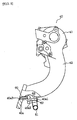
- Fig. 1 is a partially broken-away front view of a four-stroke cycle engine with a turbocharger
- Fig. 2 is a schematic plan view showing the construction of the four-stroke cycle engine with turbocharger.
- the four-stroke cycle engine 1 of this embodiment is, for example, of a four cylinder type, in which piston operation causes pulsation of the inside pressure of the crank case.
- An engine body 2 of the four-stroke cycle engine 1 comprises a cylinder block 3, a crank case 4, an oil pan 5, a cylinder head 6 and a head cover 7. Between the cylinder block 3 and the crank case 4 is journaled a crank shaft 8, and within each cylinder bore 10 in the cylinder block 3 is disposed for reciprocal movement a piston 11, which is connected to the crank shaft 8 through a connecting rod 12.
- exhaust ports 13 and intake ports 14 of which the openings to a combustion chamber in each cylinder are opened/closed by exhaust valves 16 and intake valves 17.
- the exhaust and intake valves 16, 17 are driven by cams 20, 21 provided on cam shafts 18, 19, which are adapted to be rotated by the crank shaft 8 through cam chains (not shown).
- ignition plugs 22 facing combustion chambers 15.
- an exhaust pipe 30 in communication with exhaust ports 13, and the exhaust pipe 30 is connected to a turbine 31 and further to a muffler 32 through a catalyst (not shown).
- an intake manifold 40 in communication with intake ports 14.
- the intake manifold 40 is provided with a surge tank 41, the downstream side of which is branched into four intake passages 42, which are connected to the respective cylinders.
- a throttle body 43 Upstream of the surge tank 41 is provided a throttle body 43, which is equipped with a throttle valve 44 for controlling the intake airflow rate.
- an intercooler 45 To the throttle body 43 is connected an intercooler 45, to which is connected a compressor 47 through an intake pipe 46, and the compressor 47 and the turbine 31 are driven in association with each other.
- the intake pipe 48 is provided with a sub-intake passage 50 connecting the upstream side and the downstream side of the throttle valve 44, and in the middle of the sub-intake passage 50 are disposed a control valve 51 for controlling the intake air flow rate, and a check valve 52 downstream of the control valve 51.
- the upstream side 50a end of the sub-intake passage 50 is open to the intake pipe 48, and the downstream side 50b ends are open to intake ports 14, air being supplied from the upstream side of an injector 53 on the cylinder head 6.
- the sub-intake passage 50 is branched into first branch passages 50c1 and second branch passages 50c2 in two stages, and the branched passages 50c are open to intake ports 14 in the respective cylinders through delivery passages 50b, whereby uniformity of the intake flow rate can be achieved for each cylinder, providing stability of combustion.
- downstream side ends of a sub-intake passage 50 bypassing the throttle valve 44 for air-intake are open to intake ports 14, so that intake air turbulence due to air induction during idling, especially during first idling after cold starting, facilitates mixture of air with fuel, providing stable combustion after cold starting.
- the check valve 52 is disposed on the downstream side of the sub-intake passage 50 from the control valve 51, so that the check valve 52 allows for prevention of engine hunting due to pulsation of intake air during deceleration, and reduction of leakage of supercharged pressure.
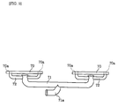
- Fig. 3 is a schematic view showing the construction of another embodiment of the four-stroke cycle engine with turbocharger.
- all of the four intake passages 42 are bent in the same direction, and the downstream ends of the sub-intake passage 50 are each open to the intake passages 42 at their outwardly bent sides where air velocity is large, so that air-intake from the intake ports 14 can be performed smoothly.
- Fig. 4 through Fig. 12 show examples of the construction in which the sub-intake passage downstream of the check valve 52 is branched in two stages and the branched passages are opened to the intake ports in the respective cylinders.
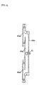
- Fig. 4 is a front view of an intake manifold
- Fig. 5 is a partially broken-away side view of the intake manifold
- Fig. 6 is a plan view of a cylinder head connection section
- Fig. 7 is a side view of a lid.
- first head side branch paths 40a1 branched from the sub-intake passage 50 downstream of the check valve 52, second head side branch paths 40a2 branched further from the first head side branch paths 40a1 and delivery passages 40a3 having downstream openings through which air is delivered from the second head side branch paths 42a2 to intake ports of the cylinders, are formed integrally.
- the delivery passages 40a3 are open to the mating surface to the cylinder.
- the delivery passages 40a3 are in communication with the second head side branch paths 40a2, and constituted by pipes force-fitted in machined holes. The pipe may be held with a gasket against coming off.
- a lid 62 having an intake air induction section 61 connected to the downstream side from the check valve 52, covering the first and second head side branch paths 40a1, 40a2.
- Fig. 8 is a partially broken-away side view of an intake manifold
- Fig. 9 is a side view of branch piping
- Fig. 10 is a plan view of the branch piping.
- delivery passages 40a3 having downstream openings through which air is delivered to the intake ports 14, are formed integrally.
- the delivery passages 40a3 are not open to the mating surfaces to the cylinder, it may extends to the mating surfaces for opening.
- the delivery passages 40a3 are constituted by machined holes and in communication with communication holes 70a in the lids 70.
- the branch piping has a first branch pipe 71 with an intake induction section 71a connected to the downstream side from the check valve 52, and second branch pipes 72 branched further from the first branch pipe 71, and the second branch pipes 72 are connected to lids 70, in alignment with the communication holes 70a.
- the lids are attached to the cylinder head connection sections 40a through sealing members 63 of gaskets.
- the sub-intake passage downstream of the check valve 52 is branched in two stages and the branched passages can be open to intake ports in the respective cylinders.
- Fig. 11 is a partially broken-away side view of an intake manifold
- Fig. 12 is a sectional view along line XII-XII of Fig. 11.
- head side branch passages 40e branched from the sub-intake passage 50 downstream of the check valve 52, and delivery passages 40a3 having downstream openings through which air is delivered from the head side branch passages 40e to intake ports of the cylinders, are formed integrally.
- the sub-intake passage 50 downstream of the check valve 52 is branched in two stages and the branched passages can be open to intake ports 14 in the respective cylinders.
- the downstream side ends of a sub-intake passage bypassing a throttle valve for air-intake are open to intake ports, so that intake air turbulence due to air induction during idling, especially during first idling after cold starting, facilitates mixture of air with fuel, providing stable combustion after cold starting.
- a check valve is disposed on the downstream side of the sub-intake passage from the control valve, so that the check valve allows for prevention of engine hunting due to pulsation of intake air during deceleration, and reduction of leakage of supercharged pressure.
- uniformity of the intake airflow rate can be achieved for each cylinder, effecting stability of combustion.
- the sub-intake passage downstream of the check valve is branched in two stages and the branched passages can be open to intake ports in the respective cylinders.
- the sub-intake passage downstream of the check valve is branched in two stages and the branched passages can be open to intake ports in the respective cylinders.
- the sub-intake passage downstream of the check valve is branched in two stages and the branched passages can be open to intake ports in the respective cylinders.
Applications Claiming Priority (2)
| Application Number | Priority Date | Filing Date | Title |
|---|---|---|---|
| JP18011099A JP2001012323A (ja) | 1999-06-25 | 1999-06-25 | 4サイクルエンジン |
| JP18011099 | 1999-06-25 |
Publications (2)
| Publication Number | Publication Date |
|---|---|
| EP1063413A2 true EP1063413A2 (fr) | 2000-12-27 |
| EP1063413A3 EP1063413A3 (fr) | 2001-09-26 |
Family
ID=16077605
Family Applications (1)
| Application Number | Title | Priority Date | Filing Date |
|---|---|---|---|
| EP00113516A Withdrawn EP1063413A3 (fr) | 1999-06-25 | 2000-06-26 | Moteur à quatre temps |
Country Status (2)
| Country | Link |
|---|---|
| EP (1) | EP1063413A3 (fr) |
| JP (1) | JP2001012323A (fr) |
Cited By (5)
| Publication number | Priority date | Publication date | Assignee | Title |
|---|---|---|---|---|
| EP2236806A1 (fr) * | 2009-03-31 | 2010-10-06 | Honda Motor Co., Ltd. | Structure de passage d'admission pour moteur à combustion interne |
| CN103306809A (zh) * | 2012-03-06 | 2013-09-18 | 赵广平 | 二冲程摆动活塞式内燃机 |
| US9874182B2 (en) * | 2013-12-27 | 2018-01-23 | Chris P. Theodore | Partial forced induction system |
| CN115443377A (zh) * | 2020-07-06 | 2022-12-06 | 三菱自动车工业株式会社 | 内燃机 |
| WO2023093114A1 (fr) * | 2021-11-26 | 2023-06-01 | 广州汽车集团股份有限公司 | Dispositif d'admission d'air |
Families Citing this family (1)
| Publication number | Priority date | Publication date | Assignee | Title |
|---|---|---|---|---|
| JP2010031688A (ja) * | 2008-07-25 | 2010-02-12 | Yamaha Motor Co Ltd | 火花点火式内燃機関 |
Family Cites Families (6)
| Publication number | Priority date | Publication date | Assignee | Title |
|---|---|---|---|---|
| FR1589465A (fr) * | 1968-09-19 | 1970-03-31 | ||
| JPS6060007B2 (ja) * | 1978-05-22 | 1985-12-27 | トヨタ自動車株式会社 | カウンタフロ−型多気筒内燃機関の吸気装置 |
| JPS57157014A (en) * | 1981-03-23 | 1982-09-28 | Mitsubishi Motors Corp | Air intake unit of supercharged engine |
| JPS5987229A (ja) * | 1982-11-12 | 1984-05-19 | Suzuki Motor Co Ltd | 内燃機関の吸気装置 |
| FR2690713B1 (fr) * | 1992-04-30 | 1996-01-26 | Renault | Dispositif d'admission pour moteur a combustion interne. |
| JPH0666226A (ja) * | 1992-08-11 | 1994-03-08 | Mitsubishi Electric Corp | 内燃機関の燃料噴射装置 |
-
1999
- 1999-06-25 JP JP18011099A patent/JP2001012323A/ja active Pending
-
2000
- 2000-06-26 EP EP00113516A patent/EP1063413A3/fr not_active Withdrawn
Non-Patent Citations (1)
| Title |
|---|
| None |
Cited By (9)
| Publication number | Priority date | Publication date | Assignee | Title |
|---|---|---|---|---|
| EP2236806A1 (fr) * | 2009-03-31 | 2010-10-06 | Honda Motor Co., Ltd. | Structure de passage d'admission pour moteur à combustion interne |
| US8590511B2 (en) | 2009-03-31 | 2013-11-26 | Honda Motor Co., Ltd. | Intake passage structure for internal combustion engine, and engine and vehicle incorporating same |
| CN103306809A (zh) * | 2012-03-06 | 2013-09-18 | 赵广平 | 二冲程摆动活塞式内燃机 |
| US9874182B2 (en) * | 2013-12-27 | 2018-01-23 | Chris P. Theodore | Partial forced induction system |
| US20180142651A1 (en) * | 2013-12-27 | 2018-05-24 | Chris P. Theodore | Partial forced induction system |
| US10190547B2 (en) * | 2013-12-27 | 2019-01-29 | Chris P. Theodore | Partial forced induction system |
| CN115443377A (zh) * | 2020-07-06 | 2022-12-06 | 三菱自动车工业株式会社 | 内燃机 |
| CN115443377B (zh) * | 2020-07-06 | 2024-04-12 | 三菱自动车工业株式会社 | 内燃机 |
| WO2023093114A1 (fr) * | 2021-11-26 | 2023-06-01 | 广州汽车集团股份有限公司 | Dispositif d'admission d'air |
Also Published As
| Publication number | Publication date |
|---|---|
| EP1063413A3 (fr) | 2001-09-26 |
| JP2001012323A (ja) | 2001-01-16 |
Similar Documents
| Publication | Publication Date | Title |
|---|---|---|
| US10215084B2 (en) | Directly communicated turbocharger | |
| US5000131A (en) | Exhaust port control valve for two stroke engine | |
| US10145277B2 (en) | Crankcase ventilation for turbocharged engine | |
| EP1612390A3 (fr) | Système de turbocompresseur et de flux de recyclage des gaz d'échappement | |
| US4998512A (en) | Exhaust port control system for two stroke engine | |
| JP3626493B2 (ja) | 4サイクル内燃エンジンのシリンダヘッド | |
| EP1063413A2 (fr) | Moteur à quatre temps | |
| US6230696B1 (en) | Internal combustion engine, especially diesel-internal combustion engine | |
| EP3808966B1 (fr) | Dispositif d'admission d'air pour moteur | |
| US20130104817A1 (en) | Engine assembly including crankcase ventilation system | |
| US11236706B2 (en) | Evaporated fuel treatment device for engine | |
| JPS6126569Y2 (fr) | ||
| JP4860451B2 (ja) | 内燃機関 | |
| JP3106724B2 (ja) | V型エンジンの吸気装置 | |
| EP1081351A3 (fr) | Système d'admission pour moteur à combustion interne | |
| JP2012036805A (ja) | 熱交換部材、および、それを用いた吸気システム | |
| EP1065356A3 (fr) | Moteur à combustion interne à quatre temps | |
| JPS5922287Y2 (ja) | 多気筒内燃機関のegr通路装置 | |
| EP0930431A3 (fr) | Système d'admission pour moteur à combustion interne à au moins deux cylindres | |
| JP2555048Y2 (ja) | エンジンの排気浄化用二次空気導入通路 | |
| JP3382711B2 (ja) | 排気ターボ過給機付きdohc型内燃機関 | |
| JP2756157B2 (ja) | 4サイクルエンジン | |
| JPS6132123Y2 (fr) | ||
| JPS6030422A (ja) | 4サイクルエンジンの吸気装置 | |
| JPH04164110A (ja) | 内燃機関のブローバイガス通路装置 |
Legal Events
| Date | Code | Title | Description |
|---|---|---|---|
| PUAI | Public reference made under article 153(3) epc to a published international application that has entered the european phase |
Free format text: ORIGINAL CODE: 0009012 |
|
| AK | Designated contracting states |
Kind code of ref document: A2 Designated state(s): AT BE CH CY DE DK ES FI FR GB GR IE IT LI LU MC NL PT SE Kind code of ref document: A2 Designated state(s): DE ES FR GB IT |
|
| AX | Request for extension of the european patent |
Free format text: AL;LT;LV;MK;RO;SI |
|
| PUAL | Search report despatched |
Free format text: ORIGINAL CODE: 0009013 |
|
| AK | Designated contracting states |
Kind code of ref document: A3 Designated state(s): AT BE CH CY DE DK ES FI FR GB GR IE IT LI LU MC NL PT SE |
|
| AX | Request for extension of the european patent |
Free format text: AL;LT;LV;MK;RO;SI |
|
| 17P | Request for examination filed |
Effective date: 20011022 |
|
| AKX | Designation fees paid |
Free format text: DE ES FR GB IT |
|
| GRAP | Despatch of communication of intention to grant a patent |
Free format text: ORIGINAL CODE: EPIDOSNIGR1 |
|
| STAA | Information on the status of an ep patent application or granted ep patent |
Free format text: STATUS: THE APPLICATION IS DEEMED TO BE WITHDRAWN |
|
| 18D | Application deemed to be withdrawn |
Effective date: 20041230 |