EP1062986A2 - Implantierbares elektronisches Gerät - Google Patents
Implantierbares elektronisches Gerät Download PDFInfo
- Publication number
- EP1062986A2 EP1062986A2 EP00250205A EP00250205A EP1062986A2 EP 1062986 A2 EP1062986 A2 EP 1062986A2 EP 00250205 A EP00250205 A EP 00250205A EP 00250205 A EP00250205 A EP 00250205A EP 1062986 A2 EP1062986 A2 EP 1062986A2
- Authority
- EP
- European Patent Office
- Prior art keywords
- electronic device
- plug
- contact element
- cam
- clamping
- Prior art date
- Legal status (The legal status is an assumption and is not a legal conclusion. Google has not performed a legal analysis and makes no representation as to the accuracy of the status listed.)
- Granted
Links
- 230000015572 biosynthetic process Effects 0.000 claims abstract description 3
- 230000000694 effects Effects 0.000 claims description 6
- 238000013459 approach Methods 0.000 claims description 4
- 230000005540 biological transmission Effects 0.000 claims description 3
- 238000012546 transfer Methods 0.000 claims description 3
- 230000000747 cardiac effect Effects 0.000 claims description 2
- 230000002441 reversible effect Effects 0.000 claims description 2
- 238000011161 development Methods 0.000 description 4
- 230000018109 developmental process Effects 0.000 description 4
- 238000003780 insertion Methods 0.000 description 3
- 230000037431 insertion Effects 0.000 description 3
- 210000000078 claw Anatomy 0.000 description 2
- 210000002105 tongue Anatomy 0.000 description 2
- 238000003466 welding Methods 0.000 description 2
- 230000000712 assembly Effects 0.000 description 1
- 238000000429 assembly Methods 0.000 description 1
- 238000005452 bending Methods 0.000 description 1
- 230000009286 beneficial effect Effects 0.000 description 1
- 238000010276 construction Methods 0.000 description 1
- 230000008878 coupling Effects 0.000 description 1
- 238000010168 coupling process Methods 0.000 description 1
- 238000005859 coupling reaction Methods 0.000 description 1
- 238000013461 design Methods 0.000 description 1
- 230000002349 favourable effect Effects 0.000 description 1
- 238000002513 implantation Methods 0.000 description 1
- 238000009413 insulation Methods 0.000 description 1
- 230000003993 interaction Effects 0.000 description 1
Images


Classifications
-
- A—HUMAN NECESSITIES
- A61—MEDICAL OR VETERINARY SCIENCE; HYGIENE
- A61N—ELECTROTHERAPY; MAGNETOTHERAPY; RADIATION THERAPY; ULTRASOUND THERAPY
- A61N1/00—Electrotherapy; Circuits therefor
- A61N1/18—Applying electric currents by contact electrodes
- A61N1/32—Applying electric currents by contact electrodes alternating or intermittent currents
- A61N1/36—Applying electric currents by contact electrodes alternating or intermittent currents for stimulation
- A61N1/372—Arrangements in connection with the implantation of stimulators
- A61N1/375—Constructional arrangements, e.g. casings
- A61N1/3752—Details of casing-lead connections
-
- Y—GENERAL TAGGING OF NEW TECHNOLOGICAL DEVELOPMENTS; GENERAL TAGGING OF CROSS-SECTIONAL TECHNOLOGIES SPANNING OVER SEVERAL SECTIONS OF THE IPC; TECHNICAL SUBJECTS COVERED BY FORMER USPC CROSS-REFERENCE ART COLLECTIONS [XRACs] AND DIGESTS
- Y10—TECHNICAL SUBJECTS COVERED BY FORMER USPC
- Y10S—TECHNICAL SUBJECTS COVERED BY FORMER USPC CROSS-REFERENCE ART COLLECTIONS [XRACs] AND DIGESTS
- Y10S439/00—Electrical connectors
- Y10S439/907—Contact having three contact surfaces, including diverse surface
Definitions
- the invention relates to an implantable electronic device according to the preamble of claim 1.
- the known, relatively complicated locking devices have the disadvantage that when it is operated, especially when the lock is released, are very difficult to handle because the locking devices only through a front or side to be initiated manually from the header wall Pressure force can be released. Furthermore, it is not disadvantageous recognizable whether the connector located in the connection device really has been locked.
- This locking device is designed as a complicated molded part and has the further disadvantage that the clamping effect of the shaft to hold the or the connector (s) is limited to the area of the line insulation of an electrode line is. This essentially only results in mechanical strain relief the electrode line without the actual contact points necessarily must be secured. So there is no statement about the quality of the contact possible if the plug of the electrode cable has the contact area intended for it after insertion, for example, not or only partially reached. In addition, damage to the wiring harnesses or a short circuit between individual cable runs cannot be excluded with certainty.
- the invention therefore lies the task is based on an implantable electronic device mentioned type with a locking device for the plug one with to specify the device connectable, coaxial electrode line through which with simple means of fixing the plug in place on the electrode lead acting, essentially axially directed, tensile load achievable and at the same time there is certainly good contact.
- the invention includes the finding that when using an eccentric, by a lever of a manually activated spa operation due to the leverage even with a relatively small swivel movement through the eccentric great force effect can be achieved, which is preferred for generating clamping forces can be used between two bodies.
- the eccentricity and the shape of the eccentric is a convenient dosage of the clamping force generated possible depending on the size of the swivel angle.
- an implantable electronic device preferably a cardiac pacemaker, arranged, essentially socket-shaped Connection device for the plug of a coaxial electrode line a locking device on which consists of a manually operated, eccentric stored clamping cam and a contact element provided in the connecting device for the different pole of the plug one with the pacemaker coaxial electrode line to be connected is formed.
- the eccentrically mounted clamping cam is on its edge with the contact element in operative engagement, so that a rotary movement of the clamping cam on the contact element is transmitted. This will make it the different pole of the connector form-fitting encompassing contact element so reversibly deformed that between the different pole and the contact element a non-positive connection arises, which fixes the plug within the connection device and at the same time an improved galvanic contact between the contact element and the differentenn pole of the connector.
- the contact element on the plug receptacle of the connection device by welding attached.
- the contact element consisting of a spring material is tongue-shaped formed and extends substantially transversely to the longitudinal axis of the Connecting device. It has a hole through which the different pole of the connector located in the connector is guided.
- the is eccentrically mounted Spannock formed essentially disc-shaped, using a Bearing journal stored in the header and with that on the side wall of the header arranged hand lever connected to generate a rotary movement.
- the axis of rotation of the eccentrically mounted clamping cam extends essentially perpendicular to the axis of the plug of the electrode line, so that the free End of the contact element on the edge of the eccentrically mounted clamping cam supports. Because the distance of the edge with respect to the axis of rotation of the clamping cam changes when twisting, the resilient contact element is through a rotary movement of the clamping cam generated by pivoting the hand lever reversibly deformable and becomes relative to the different pole of the connector producing a non-positive connection, in particular a clamp connection, moved with this.
- This positive connection is created in a simple manner by the fact that the one determined by projection onto the cross-sectional area of the different pole, free diameter of the bore located in the contact element is reduced. This caused by clamping action with a relatively small deflection of the contact element a sufficiently large holding force between the different pole and the Contact element for fixing the connector in the event of an axial tensile load on the coaxial electrode lead.
- the has eccentric stored clamping cam essentially in the form of a circular disk, which enables the generation of a particularly uniform clamping force becomes. At the same time, the effort required for using the hand lever the generation of the clamping force required to fix the connector relatively low.
- the locking of the plug of a coaxial electrode line in a pacemaker to be implanted can be handled very comfortably, what is of particular advantage, for example, under operating conditions.
- the contact element to generate the clamping effect by reversible deformation using the eccentrically mounted tensioning cam from a relaxed state to a tensioned one Condition is transferred.
- a rotation range for the clamping cam preferably 90 ° is provided for operating the locking device arranged on the outside of the header, with the tensioning cam connected hand lever in a to the axis of the connecting device essentially vertical position when the locking device is opened.
- closed Locking extends the hand lever substantially parallel to Axis of the connecting device and thereby fits in one, especially for the implantation of the pacemaker, advantageously to the shape of the Headers.
- the Outside of the header and the side of the free end facing the header of the hand lever each provided a locking means, which is when closed Locking device are non-positively and / or positively engaged and the Hand lever against an unwanted to open the locking device fix leading return movement.
- the locking means are as an approach and one Approach-receiving groove of appropriate size.
- the contact element is in two parts formed, with a bore in each of the sections for receiving the different Poles of a plug located in a connection device is provided. This makes it easy to use an eccentric stored tensioning cam at the same time for the plug of two electrode lines each form a locking device.
- the two sections of the contact element are made of a plastic connector coupled with each other since the plugs of the individual coaxial electrode lines lead a different potential and avoid equipotential bonding must become.
- the eccentrically mounted clamping cam between two essentially the same trained, vertically one above the other arranged connection devices.
- the contact elements provided on the connection devices are are of the same design and are each based on essentially mirror-symmetrical Arrangement to form a locking device on the From.
- the contact elements With a rotary movement generated by the hand lever, the eccentric mounted clamping cam, the contact elements simultaneously perform a swiveling movement with the opposite sense of direction, so that by a hand lever movement on both different poles to fix the corresponding one Plug required clamping force can be generated.
- each Connection device a separate, each eccentrically mounted, clamping cam is provided, the first tensioning cam being connected to a hand lever has and the rotational movement of the first clamping cam of this force and is positively transferred to the second clamping cam.
- the two eccentrically mounted clamping cams indicate the rotational movement each have a bearing journal which, at least on a portion of its periphery, has external teeth.
- a for transmitting the rotary movement indirect connection between the tension cams provided which is preferred can be realized by a pinion, which the bearing pin of the clamping cam under Formation of a gear connects.
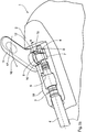
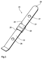
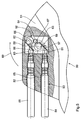
- the pacemaker 1 shown in FIGS. 1a and 1b has a header 2 on, in which a connection socket 3 is arranged, via which a coaxial Electrode line 4 using a standardized IS-1 plug 5 with the pacemaker 1 is electrically connected.
- the different pole 6 of the plug 5 plugged into the connector 3 The proximal end of the coaxial electrode line 4 is in a connector receptacle 7, which is provided within the connection socket 3.
- the connector receptacle 7 carries at its the insertion opening for the plug 5 opposite Side a contact element 8.
- the contact element 8 is tongue-shaped and consists of a spring plate.
- the attachment of the contact element 8 is one side on the wall of the connector receptacle 7, preferably by welding, made that the axis of the contact element substantially extends transversely to the longitudinal axis of the connector receptacle 7 or of the connector 5.
- a receptacle 9 designed as an eccentric is arranged in the plug receptacle, which with a bearing journal 10 mounted in the wall of the header 2 a hand lever 11 is connected.
- the diameter of the clamping cam 9 is such chosen that the free end 12 of the contact element 8 on its flank (compare position 13 in FIG. 1d).
- contact element 8 In the resiliently attached to the plug receptacle 7 contact element 8 is a Bore (compare position 14 in Figure 1c) provided through which the differente pole 6 moves when the plug 5 for connecting the coaxial electrode line 4 with the pacemaker 1 inserted into the socket 3 becomes.
- the contact element 8 and the clamping cam 9 form the elements of a locking device 15, which by pivoting the hand lever 11 in the direction of Arrow 16 can be activated and from an open state in which the connector 5 can be pushed into or removed from the connecting socket 3, in the closed state is spent, in which a in the socket 3 located connector 5 against an unwanted, by one in the axial direction effective tensile force component causes sliding out of the connection socket 3 is secured.
- the locking device 15 is in the closed state by the interaction of the eccentric cam with the contact element 8 between generates a clamping force to the different pole 6 and the contact element 8, which fixes the different pole 6 of the plug 5 in the plug receptacle 7.
- the contact element 8 fastened to the plug receptacle 7 has a bore 14 on which has a free cross section when the locking device is open has sufficient size, through which the different pole 6 of the connector can move when it is pushed into the socket.
- the contact element 8 supported on the flank 13 of the eccentric cam reversibly deformed. This deformation (compare the illustration according to the Figures 2c and 2d) causes a non-positive connection between the contact element 8 and the different pole 6 located in the plug receptacle 7 of the plug.
- the respectively existing locking state of the locking device 15 is easy to recognize by the position of the hand lever 11.
- Is the Hand lever essentially transversely to the longitudinal axis of the connecting socket 3 is the Locking device opened.
- a parallel to the longitudinal axis of the connector Extending hand lever points to a closed locking device there.
- Figures 2a, 2b, 2c and 2d show the position of the elements 8 and 9 of the locking device 15 if it is in the closed state.
- the hand lever 11 is in the direction of the coaxial electrode line 4 (compare the Position 16 in Figure 1) folded so that it is on the flank 13 of the eccentric cam 9 supporting end 12 of the resilient contact element 8 in the plane of the drawing the respective figure moves to the right, which means that by projection determined on the cross-sectional area of the different pole 6, free diameter of the Hole 14 reduced.
- This causes a sufficiently large clamping action Holding force between different pole 6 and the contact element 8 at an axial Tensile load on the electrode line 4.
- the corresponding tensile force is determined by the Contact element 8 via the plug receptacle 7 or the eccentric cam 9 in the Wall of the header 2 initiated.
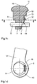
- FIG. 3 shows a contact element made of a metallic spring material 20, which consists of two, electrically insulated from each other connected sections 21 and 22.
- a coupling piece 23 is provided with two insertion pockets 24 and 25, in which one end of each of the sections 21 and 22 is pressed in and / or glued in this way are that the spring and bending properties of the entire contact element 20 of an integral contact element essentially not differentiate.
- the holes 26 and 27 can each have a different pole Take plug of a coaxial electrode line, so that by a rotational movement a clamping sock engaging on the free end 28 of the contact element 20 (Compare position 9 in Figures 1c and 2c) both at the same time Plug in the corresponding connection device against an unwanted Sliding out can be secured.
- the pacemaker 30 shown in FIG. 4 has a header 31 with two Connection sockets 32 and 33 for one plug of a coaxial electrode line 34, 35 on.
- the designed as an eccentric cam 36 is located with two, in essentially mirror-symmetrically arranged contact elements 37 and 38 in operative contact.
- the different poles 39, 40 of the plug are by a (Not designated) bore in the respective contact element and are held within this bore by clamping action when the with the eccentric cam 36 on the bearing pin 41 connected hand lever 42 in the direction of Arrow 43 is pivoted.
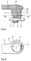
- connection socket 51 For the pacemaker 5 shown in FIG. 5, there is a header 51 with two Connection sockets 52 and 53 are provided, in each of which the plug one coaxial electrode line 54, 55 is located.
- the different poles 56, 57 of the connector are shown in their position fixed by the respective locking device.
- Plug receptacles 60 and 61 provide a welded connection.
- the contact elements extend parallel to each other.
- 57 fixing locking devices is each of the contact elements 58, 59 assigned an eccentric cam 62, 63, on which the free ends of the Support contact elements 58, 59.
- the eccentric cam 62 is driven indirectly via a pinion 64 when the Eccentric cam 63 rotates when pivoting the hand lever 65.
- the External toothing extends over half the circumference of the journal 66, 67.
Landscapes
- Health & Medical Sciences (AREA)
- Engineering & Computer Science (AREA)
- Biomedical Technology (AREA)
- Nuclear Medicine, Radiotherapy & Molecular Imaging (AREA)
- Radiology & Medical Imaging (AREA)
- Life Sciences & Earth Sciences (AREA)
- Animal Behavior & Ethology (AREA)
- General Health & Medical Sciences (AREA)
- Public Health (AREA)
- Veterinary Medicine (AREA)
- Electrotherapy Devices (AREA)
- Details Of Connecting Devices For Male And Female Coupling (AREA)
- Coupling Device And Connection With Printed Circuit (AREA)
Abstract
Description
- Figur 1a
- eine bevorzugtes Ausführungsform der Erfindung mit geöffneter Verriegelungseinrichtung in einer perspektivischen Seitenansicht,
- Figur 1b
- eine Teilansicht der in Figur 1a gezeigten Ausführungsform der Erfindung bei geöffnetem Header in perspektivischer Darstellung,
- Figur 1c
- die Darstellung der Ansicht eines Schnittes längs der Linie A...A gemäß Figur 1b,
- Figur 1d
- die Darstellung der Ansicht eines Schnittes längs der Linie B...B gemäß Figur 1c,
- Figur 2a
- die in Figur 1a gezeigte Ausführungsform der Erfindung mit geschlossener Verriegelungseinrichtung in einer perspektivischen Seitenansicht,
- Figur 2b
- eine Teilansicht der in Figur 2a gezeigten Ausführungsform der Erfindung bei geöffnetem Header in perspektivischer Darstellung,
- Figur 2c
- die Darstellung der Ansicht eines Schnittes längs der Linie C...C gemäß Figur 2b,
- Figur 2d
- die Darstellung der Ansicht eines Schnittes längs der Linie D...D gemäß Figur 2c,
- Figur 3
- eine günstige Weiterbildung der Erfindung,
- Figur 4
- eine andere vorteilhafte Ausführungsform der Erfindung in Darstellung eines Teil-Längsschnittes durch eine Anschlußvorrichtung, sowie
- Figur 5
- eine vorteilhafte Variante der in Figur 4 gezeigten Ausführungsform der Erfindung in Darstellung eines Teil-Längsschnittes.
Claims (17)
- Implantierbares elektronisches Gerät (1, 30, 50), insbesondere Herzschrittmacher, mit mindestens einer im Header (2, 31, 51) angeordneten, im wesentlichen buchsenförmigen Anschlußvorrichtung (3, 32, 33, 52, 53) für einen an dem proximalen Ende einer Elektrodenleitung (4, 34, 35, 54, 55) angeordneten Stecker, mit einer ein Kontaktelement (8, 20, 37, 38, 58, 59) aufweisenden Steckeraufnahme (7, 60, 61) für den mindestens einen differenten Pol (6, 39, 40, 56, 57) des Steckers, wobei an der Anschlußvorrichtung eine den Sitz des Steckers bei einer in axialer Richtung wirksamen Zugkraft sichernde, durch einen an der Außenseite des Headers befindlichen Handhebel (11) bedienbare, Verriegelungseinrichtung (15) vorgesehen ist, dadurch gekennzeichnet, daß die Verriegelungseinrichtung (15) durch das Kontaktelement (8, 20, 37, 38, 58, 59) und eine in der Anschlußvorrichtung (3, 32, 33, 52, 53) exzentrisch gelagerte Spannocke (9, 36, 62, 63) gebildet ist, wobei das federnd angeordnete Kontaktelementdaß bei einer Drehbewegung der Spannocke eine Veränderung der Lage und/oder der Form des Kontaktelements relativ zu dem differenten Pol des Steckers eine kraftschlüssigen Verbindung zwischen dem differenten Pol und dem Kontaktelement zwecks Fixation des Steckers und Herstellung eines galvanischen Kontakts erzwungen wird.den differenten Pol (6, 39, 40, 56, 57) des Steckers umgreift undderart mit der Spannocke (9, 36, 62, 63) in Wirkungseingriff steht,
- Elektronisches Gerät nach Anspruch 1, dadurch gekennzeichnet, daß eine scheibenförmige Spannocke (9, 36, 62, 63) vorgesehen ist.
- Elektronisches Gerät nach Anspruch 2, dadurch gekennzeichnet, daß die Spannocke (9, 36, 62, 63) im wesentlichen die Form einer Kreisscheibe aufweist.
- Elektronisches Gerät nach Anspruch 2 oder 3, dadurch gekennzeichnet, daß sich die Drehachse der Spannocke (9, 36, 62, 63) quer zur Längsachse des Steckers erstreckt.
- Elektronisches Gerät nach einem der vorhergehenden Ansprüche, dadurch gekennzeichnet, daß das Kontaktelement (8, 20, 37, 38, 58, 59) als zungenförmiges, einseitig, bevorzugt an der Anschlußvorrichtung (3, 32, 33, 52, 53), befestigtes Federblech ausgebildet ist und sich im wesentlichen quer zur Längsachse des Steckers erstreckt.
- Elektronisches Gerät nach Anspruch 5, dadurch gekennzeichnet, daß das Kontaktelement (8, 20, 37, 38, 58, 59) eine Bohrung aufweist, durch welche der differente Pol eines in der Steckeraufnahme befindlichen Steckers geführt ist.
- Elektronisches Gerät nach einem der vorhergehenden Ansprüche, dadurch gekennzeichnet, daß sich das Kontaktelement (8, 37, 38, 58, 59) mit seinem freien Ende auf der Kurvenbahn der exzentrisch gelagerten Nocke derart abstützt, daß sich bei Verdrehen des Spannockes durch Schwenken des Kontaktelements (8, 37, 38, 58, 59) der beim Einstecken des Steckers für den differenten Pol erforderliche freie Durchmesser der Bohrung verringert und der differente Pol (6, 39, 40, 56, 57) durch eine Klemmkraft an dem Kontaktelement(8, 37, 38, 58, 59) fixiert wird.
- Elektronisches Gerät nach Anspruch 7, dadurch gekennzeichnet, daß das Kontaktelement (8, 37, 38, 58, 59) zum Erzeugen der Klemmwirkung durch reversibles Verformen mittels der Spannocke (9, 36, 62, 63) aus einem entspannten Zustand in einen gespannten Zustand überführt wird.
- Elektronisches Gerät nach Anspruch 6, dadurch gekennzeichnet, daß für den Spannocke ein Drehbereich von bevorzugt 120° vorgesehen ist.
- Elektronisches Gerät nach einem der vorhergehenden Ansprüche, dadurch gekennzeichnet, daß an der Außenseite des Headers (2, 31, 51) und der dem Header zugewandten Seite des Handhebels (11) jeweils ein Rastmittel (17, 18) vorgesehen ist, welche sich bei geschlossener Verriegelungseinrichtung (15) kraft- und/oder formschlüssig in Eingriff befinden und den Handhebel gegen eine unerwünschte, zum Öffnen der Verriegelungseinrichtung führende Rückbewegung fixieren.
- Elektronisches Gerät nach Anspruch 6, dadurch gekennzeichnet, daß die Rastmittel als Ansatz (18) und eine den Ansatz aufnehmende Auskehlung (17) entsprechender Größe ausgebildet sind.
- Elektronisches Gerät nach Anspruch 5, dadurch gekennzeichnet, daß das Kontaktelement (20) zweiteilig ausgebildet ist, wobei in jedem der Teilstücke (21, 22) eine Bohrung (26, 27) zur Aufnahme des differenten Pols eines jeweils in einer Anschlußvorrichtung(3,32,33, 52, 53) befindlichen - Steckers vorgesehen ist und die beiden Teilstücke (21,22) durch einen Verbinder (25) aus Kunststoff miteinander gekoppelt sind.
- Elektronisches Gerät nach einem der vorhergehenden Ansprüche, dadurch gekennzeichnet, daß die Spannocke (36) zwischen zwei im wesentlichen gleichartig ausgebildeten, vertikal übereinander positionierten Anschlußvorrichtungen (32, 33) angeordnet ist, deren Kontaktelemente (38, 39) sich jeweils bei im wesentlichen spiegelsymmetrischer Anordnung zwecks Bildung einer Verriegelungsvorrichtung (15) auf dem Spannocke abstützen.
- Elektronisches Gerät nach Anspruch 13, dadurch gekennzeichnet, daß für jede Anschlußvorrichtung (52, 53) eine gesonderte Spannocke (62, 63) vorgesehen ist, wobei die erste Spannnocke (63) mit einem Handhebel (65) verbunden ist und die Drehbewegung der ersten Spannocke (63) von diesem kraft- und formschlüssig auf die zweite Spannocke (62) übertragen wird.
- Elektronisches Gerät nach Anspruch 14, dadurch gekennzeichnet, daß die Spannocken (62, 63) je einen Lagerzapfen (66, 67) aufweisen, welche zur Übertragung der Drehbewegung, zumindest an einem Abschnitt ihrer Peripherie, eine Außenverzahnung (68) tragen.
- Elektronisches Gerät nach Anspruch 15, dadurch gekennzeichnet, daß zur Übertragung der Drehbewegung eine mittelbare Verbindung zwischen den Spannocken (62, 63) vorgesehen ist.
- Elektronisches Gerät nach Anspruch 16, dadurch gekennzeichnet, daß die die Außenverzahnung (68) der Lagerzapfen (66, 67) der Spannocken (62, 63) direkt oder über ein Ritzel (64) in Eingriff steht.
Applications Claiming Priority (2)
| Application Number | Priority Date | Filing Date | Title |
|---|---|---|---|
| DE19930238 | 1999-06-25 | ||
| DE19930238A DE19930238A1 (de) | 1999-06-25 | 1999-06-25 | Implantierbares elektronisches Gerät |
Publications (3)
| Publication Number | Publication Date |
|---|---|
| EP1062986A2 true EP1062986A2 (de) | 2000-12-27 |
| EP1062986A3 EP1062986A3 (de) | 2004-01-21 |
| EP1062986B1 EP1062986B1 (de) | 2006-04-05 |
Family
ID=7913234
Family Applications (1)
| Application Number | Title | Priority Date | Filing Date |
|---|---|---|---|
| EP00250205A Expired - Lifetime EP1062986B1 (de) | 1999-06-25 | 2000-06-23 | Implantierbares elektronisches Gerät mit Anschluss- und Verriegelungseinrichtung |
Country Status (4)
| Country | Link |
|---|---|
| US (1) | US6312297B1 (de) |
| EP (1) | EP1062986B1 (de) |
| AT (1) | ATE322306T1 (de) |
| DE (2) | DE19930238A1 (de) |
Cited By (6)
| Publication number | Priority date | Publication date | Assignee | Title |
|---|---|---|---|---|
| EP2477690A4 (de) * | 2009-09-15 | 2013-06-05 | Deringer Ney Inc | Elektrisches verbindungssystem und -verfahren für implantierbare medizinische vorrichtungen |
| US8494636B2 (en) | 2011-03-29 | 2013-07-23 | Greatbatch Ltd. | Feed-through connector assembly for implantable pulse generator and method of use |
| US8738141B2 (en) | 2011-04-07 | 2014-05-27 | Greatbatch, Ltd. | Contact assembly for implantable pulse generator and method of use |
| US9112325B2 (en) | 2006-11-15 | 2015-08-18 | Biotronik Crm Patent Ag | Contact configuration, contact assembly, implantable apparatus and electrode line |
| US9138586B2 (en) | 2012-01-27 | 2015-09-22 | Greatbatch Ltd. | Contact block using spherical electrical contacts for electrically contacting implantable leads |
| US9931513B2 (en) | 2011-03-29 | 2018-04-03 | Nuvectra Corporation | Feed-through connector assembly for implantable pulse generator and method of use |
Families Citing this family (12)
| Publication number | Priority date | Publication date | Assignee | Title |
|---|---|---|---|---|
| US6390843B1 (en) * | 2001-06-22 | 2002-05-21 | Pacesetter, Inc. | Lead lock for implantable medical device |
| US20060089681A1 (en) * | 2004-10-21 | 2006-04-27 | Cameron Health, Inc. | Implantable medical device |
| US8206175B2 (en) * | 2007-05-03 | 2012-06-26 | Deringer-Ney, Inc. | Visual indicator of proper interconnection for an implanted medical device |
| US8038484B2 (en) | 2007-12-11 | 2011-10-18 | Tyco Healthcare Group Lp | ECG electrode connector |
| USD737979S1 (en) | 2008-12-09 | 2015-09-01 | Covidien Lp | ECG electrode connector |
| EP2384788B1 (de) | 2010-05-04 | 2012-09-26 | Sorin CRM SAS | Schraubenloses Schnellverbindungssystem eines Sondenanschlusses an einen Generator eines implantierbaren Medizingeräts |
| CA2841601C (en) | 2011-07-22 | 2017-11-28 | David Zhou | Ecg electrode connector |
| USD771818S1 (en) | 2013-03-15 | 2016-11-15 | Covidien Lp | ECG electrode connector |
| US9408546B2 (en) * | 2013-03-15 | 2016-08-09 | Covidien Lp | Radiolucent ECG electrode system |
| WO2014149548A1 (en) | 2013-03-15 | 2014-09-25 | Covidien Lp | Electrode connector with a conductive member |
| US9943685B2 (en) | 2015-04-23 | 2018-04-17 | Cyberonics, Inc. | Lead engagement devices and methods for electrical stimulation and/or monitoring systems |
| US11617892B2 (en) | 2017-04-21 | 2023-04-04 | Medtronic, Inc. | Toolless lead connector assembly |
Citations (4)
| Publication number | Priority date | Publication date | Assignee | Title |
|---|---|---|---|---|
| US4540236A (en) | 1983-07-18 | 1985-09-10 | Cordis Corporation | Quick lock/quick release connector |
| US5252090A (en) | 1992-09-30 | 1993-10-12 | Telectronics Pacing Systems, Inc. | Self-locking implantable stimulating lead connector |
| US5697804A (en) | 1995-01-26 | 1997-12-16 | Pacesetter Ab | Implantable cardiac stimulator having a locking device for releasably retaining a pin-like element of an electrode lead |
| WO1998057702A1 (en) | 1997-06-16 | 1998-12-23 | Medtronic, Inc. | Lead connector system without a setscrew for medical devices |
Family Cites Families (6)
| Publication number | Priority date | Publication date | Assignee | Title |
|---|---|---|---|---|
| US4898173A (en) * | 1988-04-22 | 1990-02-06 | Medtronic, Inc. | In-line pacemaker connector system |
| US5195907A (en) * | 1990-05-31 | 1993-03-23 | Joseph Urban | Tooless electrical connector and conductor cable for use therewith |
| US5261395A (en) * | 1992-03-02 | 1993-11-16 | Cardiac Pacemaker, Inc. | Tooless pulse generator to lead connection |
| US6132390A (en) * | 1996-02-28 | 2000-10-17 | Eupalamus Llc | Handle for manipulation of a stylet used for deflecting a tip of a lead or catheter |
| DE19612756C1 (de) * | 1996-03-29 | 1997-09-11 | Gernot Hirse | Selbstklemmender Spannschlüssel |
| US5810628A (en) * | 1996-06-21 | 1998-09-22 | General Electric Company | Circuit breaker line and load terminal |
-
1999
- 1999-06-25 DE DE19930238A patent/DE19930238A1/de not_active Withdrawn
-
2000
- 2000-06-23 EP EP00250205A patent/EP1062986B1/de not_active Expired - Lifetime
- 2000-06-23 AT AT00250205T patent/ATE322306T1/de not_active IP Right Cessation
- 2000-06-23 DE DE50012508T patent/DE50012508D1/de not_active Expired - Lifetime
- 2000-06-26 US US09/603,414 patent/US6312297B1/en not_active Expired - Lifetime
Patent Citations (4)
| Publication number | Priority date | Publication date | Assignee | Title |
|---|---|---|---|---|
| US4540236A (en) | 1983-07-18 | 1985-09-10 | Cordis Corporation | Quick lock/quick release connector |
| US5252090A (en) | 1992-09-30 | 1993-10-12 | Telectronics Pacing Systems, Inc. | Self-locking implantable stimulating lead connector |
| US5697804A (en) | 1995-01-26 | 1997-12-16 | Pacesetter Ab | Implantable cardiac stimulator having a locking device for releasably retaining a pin-like element of an electrode lead |
| WO1998057702A1 (en) | 1997-06-16 | 1998-12-23 | Medtronic, Inc. | Lead connector system without a setscrew for medical devices |
Cited By (7)
| Publication number | Priority date | Publication date | Assignee | Title |
|---|---|---|---|---|
| US9112325B2 (en) | 2006-11-15 | 2015-08-18 | Biotronik Crm Patent Ag | Contact configuration, contact assembly, implantable apparatus and electrode line |
| EP2477690A4 (de) * | 2009-09-15 | 2013-06-05 | Deringer Ney Inc | Elektrisches verbindungssystem und -verfahren für implantierbare medizinische vorrichtungen |
| US8494636B2 (en) | 2011-03-29 | 2013-07-23 | Greatbatch Ltd. | Feed-through connector assembly for implantable pulse generator and method of use |
| US9931513B2 (en) | 2011-03-29 | 2018-04-03 | Nuvectra Corporation | Feed-through connector assembly for implantable pulse generator and method of use |
| US8738141B2 (en) | 2011-04-07 | 2014-05-27 | Greatbatch, Ltd. | Contact assembly for implantable pulse generator and method of use |
| US9492666B2 (en) | 2011-04-07 | 2016-11-15 | Nuvectra Corporation | Contact assembly for implantable pulse generator and method of use |
| US9138586B2 (en) | 2012-01-27 | 2015-09-22 | Greatbatch Ltd. | Contact block using spherical electrical contacts for electrically contacting implantable leads |
Also Published As
| Publication number | Publication date |
|---|---|
| US6312297B1 (en) | 2001-11-06 |
| ATE322306T1 (de) | 2006-04-15 |
| EP1062986B1 (de) | 2006-04-05 |
| EP1062986A3 (de) | 2004-01-21 |
| DE50012508D1 (de) | 2006-05-18 |
| DE19930238A1 (de) | 2000-12-28 |
Similar Documents
| Publication | Publication Date | Title |
|---|---|---|
| EP1062986B1 (de) | Implantierbares elektronisches Gerät mit Anschluss- und Verriegelungseinrichtung | |
| EP2367235B1 (de) | Stecker zur Verbindung mit einer Buchse | |
| EP2593994B1 (de) | Gehäuse, insbesondere für einen elektrischen kabelanschluss | |
| EP1275173A1 (de) | Stecker mit einer hülse | |
| EP3718172B1 (de) | Anschlussvorrichtung zum anschluss eines leiterendes | |
| EP3718171B1 (de) | Anschlussvorrichtung zum anschluss eines leiterendes | |
| DE102010017361A1 (de) | Anbausteckverbinder | |
| EP3973596B1 (de) | Kontaktträger | |
| DE102020110647A1 (de) | Primärverriegelung | |
| DE69530750T2 (de) | Verschlussverbindung | |
| EP3630266B1 (de) | Elektromedizinischer adapter, elektromedizinische elektrode und elektromedizinischer impulsgeber | |
| EP3659217B1 (de) | Kontakteinrichtung | |
| DE69805097T2 (de) | Steckerteil für ein schrittmachergehäuse | |
| DE102020103845A1 (de) | Baugruppe eines Steckverbinderteils, Steckverbinderteil und elektronisches Gerät | |
| DE60032856T2 (de) | Halter für modulare Verbinder, insbesondere für Verbinder mit Halbleiterplättchen sowie zusammengesetzter Verbinder | |
| WO2024052148A1 (de) | Crimpadapter, crimpanordnung und steckverbinder | |
| WO2021228321A1 (de) | Isolierkörper für schraub- und crimpkontakte | |
| DE102022105527A1 (de) | Gehäuse für eine elektrische Anschlussklemme oder eine elektrische Steckverbindung | |
| EP0448760A1 (de) | Elektrische Steckverbindung | |
| DE202020005530U1 (de) | Primärverriegelung | |
| EP3920338B1 (de) | Elektrische kontaktvorrichtung | |
| AT9874U1 (de) | Elektrische steckvorrichtung | |
| DE10346367B4 (de) | Freidrehbarer HF-Winkelsteckverbinder | |
| DE202019106024U1 (de) | Isolierkörper | |
| EP1652274B1 (de) | Steckverbindungssystem mit integrierter verriegelung |
Legal Events
| Date | Code | Title | Description |
|---|---|---|---|
| EUG | Se: european patent has lapsed | ||
| PUAI | Public reference made under article 153(3) epc to a published international application that has entered the european phase |
Free format text: ORIGINAL CODE: 0009012 |
|
| AK | Designated contracting states |
Kind code of ref document: A2 Designated state(s): AT BE CH CY DE DK ES FI FR GB GR IE IT LI LU MC NL PT SE |
|
| AX | Request for extension of the european patent |
Free format text: AL;LT;LV;MK;RO;SI |
|
| PUAL | Search report despatched |
Free format text: ORIGINAL CODE: 0009013 |
|
| AK | Designated contracting states |
Kind code of ref document: A3 Designated state(s): AT BE CH CY DE DK ES FI FR GB GR IE IT LI LU MC NL PT SE |
|
| AX | Request for extension of the european patent |
Extension state: AL LT LV MK RO SI |
|
| RIC1 | Information provided on ipc code assigned before grant |
Ipc: 7A 61N 1/375 A Ipc: 7H 01R 4/50 B |
|
| 17P | Request for examination filed |
Effective date: 20040721 |
|
| AKX | Designation fees paid |
Designated state(s): AT BE CH CY DE DK ES FI FR GB GR IE IT LI LU MC NL PT SE |
|
| GRAP | Despatch of communication of intention to grant a patent |
Free format text: ORIGINAL CODE: EPIDOSNIGR1 |
|
| RTI1 | Title (correction) |
Free format text: IMPLANTABLE ELECTRONIC DEVICE WITH CONNECTING AND LOCKING DEVICES |
|
| GRAS | Grant fee paid |
Free format text: ORIGINAL CODE: EPIDOSNIGR3 |
|
| GRAA | (expected) grant |
Free format text: ORIGINAL CODE: 0009210 |
|
| AK | Designated contracting states |
Kind code of ref document: B1 Designated state(s): AT BE CH CY DE DK ES FI FR GB GR IE IT LI LU MC NL PT SE |
|
| PG25 | Lapsed in a contracting state [announced via postgrant information from national office to epo] |
Ref country code: FI Free format text: LAPSE BECAUSE OF FAILURE TO SUBMIT A TRANSLATION OF THE DESCRIPTION OR TO PAY THE FEE WITHIN THE PRESCRIBED TIME-LIMIT Effective date: 20060405 Ref country code: IE Free format text: LAPSE BECAUSE OF FAILURE TO SUBMIT A TRANSLATION OF THE DESCRIPTION OR TO PAY THE FEE WITHIN THE PRESCRIBED TIME-LIMIT Effective date: 20060405 |
|
| REG | Reference to a national code |
Ref country code: GB Ref legal event code: FG4D Free format text: NOT ENGLISH |
|
| REG | Reference to a national code |
Ref country code: CH Ref legal event code: EP |
|
| REG | Reference to a national code |
Ref country code: IE Ref legal event code: FG4D Free format text: LANGUAGE OF EP DOCUMENT: GERMAN |
|
| REF | Corresponds to: |
Ref document number: 50012508 Country of ref document: DE Date of ref document: 20060518 Kind code of ref document: P |
|
| RAP2 | Party data changed (patent owner data changed or rights of a patent transferred) |
Owner name: BIOTRONIK GMBH & CO. KG |
|
| PGFP | Annual fee paid to national office [announced via postgrant information from national office to epo] |
Ref country code: NL Payment date: 20060619 Year of fee payment: 7 |
|
| REG | Reference to a national code |
Ref country code: SE Ref legal event code: TRGR |
|
| PGFP | Annual fee paid to national office [announced via postgrant information from national office to epo] |
Ref country code: FR Payment date: 20060621 Year of fee payment: 7 |
|
| PGFP | Annual fee paid to national office [announced via postgrant information from national office to epo] |
Ref country code: GB Payment date: 20060626 Year of fee payment: 7 |
|
| PGFP | Annual fee paid to national office [announced via postgrant information from national office to epo] |
Ref country code: CH Payment date: 20060627 Year of fee payment: 7 Ref country code: SE Payment date: 20060627 Year of fee payment: 7 |
|
| PG25 | Lapsed in a contracting state [announced via postgrant information from national office to epo] |
Ref country code: MC Free format text: LAPSE BECAUSE OF NON-PAYMENT OF DUE FEES Effective date: 20060630 Ref country code: BE Free format text: LAPSE BECAUSE OF NON-PAYMENT OF DUE FEES Effective date: 20060630 |
|
| PGFP | Annual fee paid to national office [announced via postgrant information from national office to epo] |
Ref country code: IT Payment date: 20060630 Year of fee payment: 7 |
|
| PG25 | Lapsed in a contracting state [announced via postgrant information from national office to epo] |
Ref country code: DK Free format text: LAPSE BECAUSE OF FAILURE TO SUBMIT A TRANSLATION OF THE DESCRIPTION OR TO PAY THE FEE WITHIN THE PRESCRIBED TIME-LIMIT Effective date: 20060705 |
|
| PG25 | Lapsed in a contracting state [announced via postgrant information from national office to epo] |
Ref country code: ES Free format text: LAPSE BECAUSE OF FAILURE TO SUBMIT A TRANSLATION OF THE DESCRIPTION OR TO PAY THE FEE WITHIN THE PRESCRIBED TIME-LIMIT Effective date: 20060716 |
|
| NLT2 | Nl: modifications (of names), taken from the european patent patent bulletin |
Owner name: BIOTRONIK GMBH & CO. KG Effective date: 20060607 |
|
| GBT | Gb: translation of ep patent filed (gb section 77(6)(a)/1977) |
Effective date: 20060712 |
|
| PG25 | Lapsed in a contracting state [announced via postgrant information from national office to epo] |
Ref country code: PT Free format text: LAPSE BECAUSE OF FAILURE TO SUBMIT A TRANSLATION OF THE DESCRIPTION OR TO PAY THE FEE WITHIN THE PRESCRIBED TIME-LIMIT Effective date: 20060905 |
|
| REG | Reference to a national code |
Ref country code: IE Ref legal event code: FD4D |
|
| ET | Fr: translation filed | ||
| PLBE | No opposition filed within time limit |
Free format text: ORIGINAL CODE: 0009261 |
|
| STAA | Information on the status of an ep patent application or granted ep patent |
Free format text: STATUS: NO OPPOSITION FILED WITHIN TIME LIMIT |
|
| 26N | No opposition filed |
Effective date: 20070108 |
|
| PG25 | Lapsed in a contracting state [announced via postgrant information from national office to epo] |
Ref country code: AT Free format text: LAPSE BECAUSE OF NON-PAYMENT OF DUE FEES Effective date: 20060623 |
|
| BERE | Be: lapsed |
Owner name: BIOTRONIK MESS- UND THERAPIEGERATE G.M.B.H. & CO Effective date: 20060630 |
|
| REG | Reference to a national code |
Ref country code: CH Ref legal event code: PL |
|
| EUG | Se: european patent has lapsed | ||
| GBPC | Gb: european patent ceased through non-payment of renewal fee |
Effective date: 20070623 |
|
| NLV4 | Nl: lapsed or anulled due to non-payment of the annual fee |
Effective date: 20080101 |
|
| REG | Reference to a national code |
Ref country code: FR Ref legal event code: ST Effective date: 20080229 |
|
| PG25 | Lapsed in a contracting state [announced via postgrant information from national office to epo] |
Ref country code: CH Free format text: LAPSE BECAUSE OF NON-PAYMENT OF DUE FEES Effective date: 20070630 Ref country code: GR Free format text: LAPSE BECAUSE OF FAILURE TO SUBMIT A TRANSLATION OF THE DESCRIPTION OR TO PAY THE FEE WITHIN THE PRESCRIBED TIME-LIMIT Effective date: 20060706 Ref country code: LI Free format text: LAPSE BECAUSE OF NON-PAYMENT OF DUE FEES Effective date: 20070630 Ref country code: NL Free format text: LAPSE BECAUSE OF NON-PAYMENT OF DUE FEES Effective date: 20080101 |
|
| PG25 | Lapsed in a contracting state [announced via postgrant information from national office to epo] |
Ref country code: GB Free format text: LAPSE BECAUSE OF NON-PAYMENT OF DUE FEES Effective date: 20070623 |
|
| PG25 | Lapsed in a contracting state [announced via postgrant information from national office to epo] |
Ref country code: SE Free format text: LAPSE BECAUSE OF NON-PAYMENT OF DUE FEES Effective date: 20070624 |
|
| PG25 | Lapsed in a contracting state [announced via postgrant information from national office to epo] |
Ref country code: LU Free format text: LAPSE BECAUSE OF NON-PAYMENT OF DUE FEES Effective date: 20060623 |
|
| PG25 | Lapsed in a contracting state [announced via postgrant information from national office to epo] |
Ref country code: FR Free format text: LAPSE BECAUSE OF NON-PAYMENT OF DUE FEES Effective date: 20070702 |
|
| PG25 | Lapsed in a contracting state [announced via postgrant information from national office to epo] |
Ref country code: CY Free format text: LAPSE BECAUSE OF FAILURE TO SUBMIT A TRANSLATION OF THE DESCRIPTION OR TO PAY THE FEE WITHIN THE PRESCRIBED TIME-LIMIT Effective date: 20060405 |
|
| PG25 | Lapsed in a contracting state [announced via postgrant information from national office to epo] |
Ref country code: IT Free format text: LAPSE BECAUSE OF NON-PAYMENT OF DUE FEES Effective date: 20070623 |
|
| REG | Reference to a national code |
Ref country code: DE Ref legal event code: R082 Ref document number: 50012508 Country of ref document: DE Representative=s name: RANDOLL, SOEREN, DIPL.-CHEM. UNIV. DR. RER. NA, DE |
|
| REG | Reference to a national code |
Ref country code: DE Ref legal event code: R081 Ref document number: 50012508 Country of ref document: DE Owner name: BIOTRONIK SE & CO. KG, DE Free format text: FORMER OWNER: BIOTRONIK MESS- UND THERAPIEGERAETE GMBH & CO. INGENIEURBUERO BERLIN, 12359 BERLIN, DE Effective date: 20111219 |
|
| PGFP | Annual fee paid to national office [announced via postgrant information from national office to epo] |
Ref country code: DE Payment date: 20160620 Year of fee payment: 17 |
|
| REG | Reference to a national code |
Ref country code: DE Ref legal event code: R119 Ref document number: 50012508 Country of ref document: DE |
|
| PG25 | Lapsed in a contracting state [announced via postgrant information from national office to epo] |
Ref country code: DE Free format text: LAPSE BECAUSE OF NON-PAYMENT OF DUE FEES Effective date: 20180103 |