EP1062966A1 - Ballon zum Aufweiten einer Verengung und Ballonkatheter - Google Patents
Ballon zum Aufweiten einer Verengung und Ballonkatheter Download PDFInfo
- Publication number
- EP1062966A1 EP1062966A1 EP00113074A EP00113074A EP1062966A1 EP 1062966 A1 EP1062966 A1 EP 1062966A1 EP 00113074 A EP00113074 A EP 00113074A EP 00113074 A EP00113074 A EP 00113074A EP 1062966 A1 EP1062966 A1 EP 1062966A1
- Authority
- EP
- European Patent Office
- Prior art keywords
- balloon
- stricture
- dilation
- dilating
- fixing portion
- Prior art date
- Legal status (The legal status is an assumption and is not a legal conclusion. Google has not performed a legal analysis and makes no representation as to the accuracy of the status listed.)
- Granted
Links
Images


Classifications
-
- A—HUMAN NECESSITIES
- A61—MEDICAL OR VETERINARY SCIENCE; HYGIENE
- A61M—DEVICES FOR INTRODUCING MEDIA INTO, OR ONTO, THE BODY; DEVICES FOR TRANSDUCING BODY MEDIA OR FOR TAKING MEDIA FROM THE BODY; DEVICES FOR PRODUCING OR ENDING SLEEP OR STUPOR
- A61M25/00—Catheters; Hollow probes
- A61M25/10—Balloon catheters
- A61M25/1027—Making of balloon catheters
-
- A—HUMAN NECESSITIES
- A61—MEDICAL OR VETERINARY SCIENCE; HYGIENE
- A61M—DEVICES FOR INTRODUCING MEDIA INTO, OR ONTO, THE BODY; DEVICES FOR TRANSDUCING BODY MEDIA OR FOR TAKING MEDIA FROM THE BODY; DEVICES FOR PRODUCING OR ENDING SLEEP OR STUPOR
- A61M25/00—Catheters; Hollow probes
- A61M25/10—Balloon catheters
- A61M25/1002—Balloon catheters characterised by balloon shape
-
- A—HUMAN NECESSITIES
- A61—MEDICAL OR VETERINARY SCIENCE; HYGIENE
- A61M—DEVICES FOR INTRODUCING MEDIA INTO, OR ONTO, THE BODY; DEVICES FOR TRANSDUCING BODY MEDIA OR FOR TAKING MEDIA FROM THE BODY; DEVICES FOR PRODUCING OR ENDING SLEEP OR STUPOR
- A61M25/00—Catheters; Hollow probes
- A61M25/10—Balloon catheters
- A61M2025/1043—Balloon catheters with special features or adapted for special applications
- A61M2025/1086—Balloon catheters with special features or adapted for special applications having a special balloon surface topography, e.g. pores, protuberances, spikes or grooves
-
- A—HUMAN NECESSITIES
- A61—MEDICAL OR VETERINARY SCIENCE; HYGIENE
- A61M—DEVICES FOR INTRODUCING MEDIA INTO, OR ONTO, THE BODY; DEVICES FOR TRANSDUCING BODY MEDIA OR FOR TAKING MEDIA FROM THE BODY; DEVICES FOR PRODUCING OR ENDING SLEEP OR STUPOR
- A61M25/00—Catheters; Hollow probes
- A61M25/10—Balloon catheters
- A61M25/1027—Making of balloon catheters
- A61M25/1029—Production methods of the balloon members, e.g. blow-moulding, extruding, deposition or by wrapping a plurality of layers of balloon material around a mandril
Definitions
- the present invention relates to a balloon for dilating a stricture (stenosis), and to a balloon catheter including the same.
- a balloon catheter including a balloon that can be inflated and deflated is used.
- This balloon catheter is inserted into the blood vessel from the outside of the body and inflates a balloon to dilate a stricture when the balloon reaches the stricture in the blood vessel that is a target region.
- Most of the existing balloons used for this balloon catheter are shaped like a spindle, that is, have a fixed outer diameter when they are inflated. Therefore, when they are inflated to apply pressure to the stricture from the inside of the blood vessel, they may move in a front or a rear direction (distal end or proximal end direction) by reaction force from the stricture and deviate from the stricture.
- the balloon When this deviation occurs, the balloon must be deflated, located at a proper position (the position of the stricture) and inflated again, or the balloon catheter must be exchanged with another balloon catheter having a different balloon size, thereby taking a lot of time and labor, hindering smooth treatment and increasing the burden of a patient.
- USP 4,327,736 discloses a rubber balloon, which has a fixed outer diameter over the entire length and is fixed by winding a rubber band round the center portion to prevent the deviation of the balloon from a stricture. While the balloon is being inflated, the rubber band suppresses the expanding of the center portion of the balloon so that a depression is formed in the center portion. However, this balloon is shaped like a spindle as described above and the stricture is dilated while the expanding of the center portion is suppressed with the rubber band. Therefore, the expanded diameter of the balloon changes according to a slight change in inside pressure to be applied to the balloon, thereby making it difficult to control the expanded diameter.
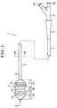
- Fig. 1 is an entire view of an embodiment of a balloon catheter comprising the balloon for dilating a stricture of the present invention (to be simply referred to as "balloon” hereinafter),
- Fig. 8 is a sectional view cut on line A-A of Fig. 1 and
- Fig. 9 is a sectional view cut on line B-B of Fig. 1.
- the right sides of Fig. 1 and Fig. 8 are illustrated as "proximal end" and the left sides as “distal end”.
- the balloon catheter 1 of the present invention has a catheter body 2, a balloon 3 attached to the periphery of the distal end portion of the catheter body 2 and a hub 5 attached to the proximal end portion of the catheter body 2 by a connection tube 4.
- the catheter body 2 has desired flexibility and may be made from a thermoplastic resin such as a polyolefin-based resin, polyamide-based resin, urethane-based resin or polyimide-based resin, or a thermosetting resin.
- a thermoplastic resin such as a polyolefin-based resin, polyamide-based resin, urethane-based resin or polyimide-based resin, or a thermosetting resin.
- the material include polyolefins such as polyethylene, polypropylene, ethylene-propylene copolymer and ethylene-vinyl acetate copolymer (EVA), polyesters such as polyvinyl chloride, polyethylene terephthalate (PET) and polybutylene terephthalate (PBT), and polyurethane-, polyamide-, polyimide- and polystyrene-based resins, fluororesin, styrene-, polyolefin-, polyvinyl chloride-, polyurethane, polyester-,
- the catheter body 2 may have a multi-layer laminate structure made from a plurality of materials.
- a lumen 21 which is the passage of a working fluid for inflating and deflating the balloon 3 and a lumen 23 for containing a guide wire (not shown) are formed in the catheter body 2.
- a side hole 22 is formed in the outer surface of the catheter body 2 internal to the balloon 3 and the distal end of the lumen 21 communicates with the side hole 22.
- the lumen 21 communicates with the inside of the balloon 3.
- the distal end of the lumen 23 is open to the distal end of the catheter body 2. This lumen 23 is used to insert the guide wire and also to supply a medical liquid etc. into the body or suck a liquid.
- the shapes of the sections of the lumens 21 and 23 are circular or oval but are not limited to these.
- the section of the lumen 21 may be shaped like a crescent in accordance with the circumference of the lumen 23.
- a lumen other than the lumens 21 and 23 may be existent.
- the dimensions (outer diameter, length, etc.) of the catheter body 2 are not particularly limited but are suitably determined according to the application purpose of the balloon catheter 1 and the case of a disease, etc.
- the outer diameter of the catheter body 2 is preferably about 0.7 to 3.0 mm and the length thereof is preferably about 30 to 150 cm.
- the hub 5 attached to the proximal end portion of the catheter body 2 is forked and ports 51 and 52 are formed in each end of branches.
- the port 51 communicates with the lumen 21 of the catheter body 2 and the port 52 communicates with the lumen 23.
- the guide wire is inserted into the lumen 23 from the port 52 to locate the distal end thereof at a position near the distal end of the lumen 23 so as to perform guiding the distal end in case of insertion of the balloon catheter 1 into the blood vessel (lumen).
- a working fluid injector such as a syringe is connected to the port 51 and operated to supply the working fluid (for example, liquid such as physiological saline, and an X-ray contrast media, air or gas such as air and carbonic acid gas) into the balloon 3 through the lumen 21 to inflate the balloon 3.
- the working fluid for example, liquid such as physiological saline, and an X-ray contrast media, air or gas such as air and carbonic acid gas
- the material of the hub 5 is not particularly limited and may be a resin material such as polyvinyl chloride, polyethylene, polypropylene, polycarbonate, polymethyl methacrylate and acrylonitrile-styrene-butadiene copolymer or a metal material.
- the balloon 3 is made of a cylindrical film whose proximal end portion and distal end portion are fixed to the outer surface of the catheter body 2 airtightly.
- the proximal end portion and distal end portion of the balloon 3 are fixed to the catheter body 2 by fusion or adhesion with an adhesive.
- the catheter body 2 may be formed as shown in Fig. 10.
- the catheter body 2 shown in Fig. 10 comprises a coaxial tube including an inner tube 2a and an outer tube 2b provided outside the inner tube 2a coaxially.
- the lumen 23 for inserting the guide wire (not shown) is formed in the inner tube 2a, and the lumen 21 serving as the passage of the working fluid for inflating or deflating the balloon 3 is formed in the approximately annular space between the inner tube 2a and the outer tube 2b.
- the proximal end portion and the distal end portion of the balloon 3 are fixed airtightly to the distal end portion of the outer tube 2b and the distal end portion of the inner tube 2a, respectively.
- the balloon 3 is preferably attached concentric or coaxially to the catheter body 2. As shown in the figure 1, the distal end of the catheter body 2 preferably projects from the distal end of the balloon 3 by a predetermined length. This projecting portion is preferably formed more flexible than other portions of the catheter body 2. Thereby, the inner wall of the blood vessel is prevented from being damaged with more certainty when the balloon catheter 1 is inserted into the blood vessel.
- the balloon 3 has a dilation function portion 30 having the function of contacting tightly or closely to the stricture (lesion site) of a lumen (typified by “the blood vessel” hereinafter) such as the blood vessel and dilating the stricture by pressure (to be referred to as “stricture dilation function” hereinafter) and a first fixing portion 31 and a second fixing portion 32 which are located on the proximal end side and distal end side of the dilation function portion 30, respectively, and have the function of fixing the balloon 3 to the blood vessel (to be referred to as "balloon fixing function" hereinafter).
- a dilation function portion 30 having the function of contacting tightly or closely to the stricture (lesion site) of a lumen (typified by “the blood vessel” hereinafter) such as the blood vessel and dilating the stricture by pressure (to be referred to as “stricture dilation function” hereinafter) and a first fixing portion 31 and a second fixing portion 32 which are located on the proximal end side and
- this balloon 3 is deflated and folded before inflation (at the time of shrinkage), when the working fluid is supplied into the inside of the balloon to inflate the balloon, it is formed into a shape which will be described below.
- the first fixing portion 31 and the second fixing portion 32 can fix the balloon 3 to the blood vessel at the both ends of the stricture without fail, the balloon 3 is prevented from being dislocated from the stricture, and the stricture can be dilated properly and surely.
- D 1 and D 2 are almost equal to each other.
- ⁇ D (D 1 + D 2 )/2 - D 0
- ⁇ D preferably satisfies the expression 0.02D 0 ⁇ ⁇ D ⁇ 0.4D 0 , more preferably the expression 0.05D 0 ⁇ ⁇ D ⁇ 0.3D 0 .
- ⁇ D is smaller than 0.02D 0 , the difference of outer diameter between the dilation function portion 30 and the first fixing portion 31/the second fixing portion 32 is small and the balloon fixing function may not be fully exhibited according to other conditions.
- ⁇ D is larger than 0.4D 0
- the difference of outer diameter between the dilation function portion 30 and the first fixing portion 31/the second fixing portion 32 is large and the stricture dilation function of the dilation function portion 30 may not be fully exhibited according to the shape, size and the like of the stricture and the operation of removing the balloon catheter 1 by deflating the balloon 3 again after inflation may be difficult.
- ⁇ D is preferably about 0.02 to 20 mm, more preferably about 0.1 to 8 mm, much more preferably about 0.4 to 3.6 mm.
- ⁇ D is smaller than 0.02 mm, the difference of outer diameter between the dilation function portion 30 and the first fixing portion 31/the second fixing portion 32 is small and the balloon fixing function may not be fully exhibited according to other conditions.
- ⁇ D is larger than 20 mm, the difference of outer diameter between the dilation function portion 30 and the first fixing portion 31/the second fixing portion 32 is large and the stricture dilation function of the dilation function portion 30 may not be fully exhibited according to the shape, size and the like of the stricture and the operation of removing the balloon catheter 1 by deflating the balloon 3 again after inflation may be difficult.
- the value of D 0 is not particularly limited and is suitably determined according to the application purpose of the balloon catheter 1 and the case of a disease. It is preferably about 1 to 30 mm, more preferably about 2 to 20 mm, much more preferably about 3 to 9 mm.
- Fig. 11 is a graph showing an example of the relationship between the inside pressure of the balloon 3 and the outer diameter of the balloon 3 (the respective outer diameters of the dilation function portion 30 and the first fixing portion 31/the second fixing portion 32). It is needless to say that the curve of the graph changes according to the material, size and production conditions etc. of the balloon 3.
- the outer diameter of the balloon 3 gradually increases.
- the inside pressure of the balloon 3 reaches the first dilation pressure at which the balloon 3 (dilation function portion 30) expands almost to a predetermined nominal diameter
- the increase rate of the outer diameter of the balloon 3 sharply decreases
- the outer diameter of the balloon 3 is rarely increased by further raising the inside pressure of the balloon 3 (little compliance), and the balloon 3 ruptures in the end.
- the inside pressure of the balloon 3 just before this rupture is represented by second dilation pressure.
- the balloon 3 of the present invention preferably satisfies the expression D 0 max - D 0 ⁇ 0.15D 0 , more preferably the expression D 0 max - D 0 ⁇ 0.1D 0 when the minimum outer diameter of the dilation function portion 30 under the second dilation pressure is represented by D 0 max.
- the length L 0 in the axial direction of the dilation function portion 30 under the first dilation pressure, the length L 1 in the axial direction of the first fixing portion 31 under the first dilation pressure and the length L 2 in the axial direction of the second fixing portion 32 under the first dilation pressure are not particularly limited but preferably are in the following ranges.
- L 0 is preferably in the range of about 5 to 50 mm, more preferably about 10 to 40 mm.
- L 1 and L 2 are preferably about 1 to 8 mm, more preferably about 2 to 4 mm. Further, it is preferable that the outer surfaces of the first fixing portion 31, the dilation function portion 30 and the second fixing portion 32 of the balloon 3 under the first dilation pressure are connected to one another by a continuous curved surface (smooth curved surface) in the axial direction, that is, a change in the outer diameter of the balloon 3 in the axial direction is continuous. Thus, an increase in the size of the balloon 3 is prevented and an excellent balloon fixing function can be exhibited. In this embodiment, L 1 and L 2 are almost equal to each other.
- the above size conditions are particularly preferred in a balloon catheter used in the PTA of a shunt formed by inosculating the radial artery with the cephalic vein or a shunt formed by inosculating the radial artery with the radial cutaneous vein.
- the balloon 3 having the above characteristic can control the required expanded diameter easily, appropriate dilation pressure is applied to the stricture without fail and the inflated balloon 3 is fixed without fail and is not dislocated in front and rear directions, the PTA of the stricture can be carried out easily and properly, the time required for PTA can be shortened, and the burden of a patient is reduced.
- the balloon 3 is made from various kinds of polymer material (particularly a thermoplastic resin).
- the entire balloon 3 is preferably made from a material having flexibility but relatively small elasticity (elongation).
- Illustrative examples of the material of the balloon 3 include polyester resins such as polyethylene terephthalate, polyethylene naphthalate, polybutylerte terephthalate and polybutylene naphthalate, polyester elastomers containing these, olefin-based resins such as polyethylene and polypropylene, crosslinked products thereof (particularly crosslinked by exposure to electron beams), polyamide-based resins such as nylon 11, nylon 12 and nylon 610, polyamide elastomers containing these, polyurethane resins, ethylene-vinyl acetate copolymer, cross linked products thereof, polymer blends containing at least one of these, polymer alloys and the like.
- polyester resins such as polyethylene terephthalate, polyethylene naphthalate, polybutylerte terephthalate and polybutylene naphthalate
- polyester elastomers containing these, olefin-based resins such as polyethylene and polypropylene, crosslinked products thereof (
- the balloon 3 may be made from a laminate consisting of a plurality of films made from these materials.
- the laminate can be obtained by, for example, coextruding and forming each layer and bonding these layers by adhesion or fusion, or forming other layers on one layer by coating.
- a soft resin layer, lubricating material layer, anti-thrombic material layer, or the like may be formed on the exterior side or interior side of the laminate made from the above materials.
- the material of the balloon 3 may contain an anti-thrombic material such as heparin, prostaglandin, urokinase or arginine derivative and an X-ray impermeable material such as barium sulfate, barium carbonate, bismuth oxide or tungsten which functions as a marker to be described hereinafter.
- the X-ray impermeable material may be existent on the dilation function portion 30 alone (for instance, a layer containing an X-ray impermeable material is formed only on the interior side of the dilation function portion 30).
- the above balloon 3 can be produced by biaxial orientation and blow molding as will be described hereinafter.
- a tube (cylinder) made from the above material is stretched to a predetermined length at an appropriate temperature (for example, 150 to 300°C).
- an appropriate temperature for example, 150 to 300°C.
- the tube is stretched in an axial direction (longitudinal direction of the catheter body 2).
- the stretched tube is inflated in a metal mold and blow molded.
- the molding space (cavity) of the metal mold is made almost the same shape as the shape of the inflated balloon 3.
- high-pressure gas such as nitrogen gas is injected into the tube.
- the temperature of the tube is raised by heating the metal mold to soften the tube and inflate it in a radial direction.
- the tube is stretched in a direction different from the axial direction of the first stretching with the result that the balloon 3 is obtained by biaxial orientation.
- the stretching in the axial direction of the tube may be carried out after blow molding.
- the balloon 3 having high dimensional accuracy and small fluctuations in shape, filmstrength, characteristics, etc. can be produced easily by employing the above production process.
- the above blow molding is carried out using a metal mold having a diameter smaller than the desired size, portions corresponding to a tapered portion on the proximal end side from the first fixing portion 31 (tapered portion between the first fixing portion 31 and a connection portion with the catheter body 2) and/or the second fixing portion 32 (tapered portion between the first fixing portion 31 and a connection portion with the catheter body 2) of the molded product are stretched in an axial direction at a temperature below the glass transition point of the resin to make the tapered portion thinner, and the molded product is set in a metal mold having a desired size and shape and is blow molded by heating and pressurizing.
- a balloon having a relatively thin tapered portion can be obtained and the deflated balloon can be folded or wound round the catheter body 2 in a compact manner.
- the balloon 3 of the present invention can be produced by the above process. However, since the balloon 3 satisfies the conditions D 0 ⁇ D 1 and D 0 ⁇ D 2 as described above, the first fixing portion 31 and the second fixing portion 32 have a larger expansion coefficient (elongation) in a radial direction than the dilation function portion 30. Therefore, there develops a difference in strength between them, whereby the first fixing portion 31 and the second fixing portion 32 rupture more easily than the dilation function portion 30 at the time of molding and use (inflation) of balloon 3.
- the thickness of the film of the first fixing portion 31 and/or the second fixing portion 32 is made larger than that of the dilation function portion 30. Describing this method in more detail, after the balloon is molded by the above biaxial orientation, blowmolding, etc., such a phenomenon that the first fixing portion 31 and/or the second fixing portion 32 are/is heated at preferably a temperature near the secondary transition point of their material to shrink only the heated portions is used to partially change the thickness.
- the thickness of the film can be partially changed by varying the elongation ratios in a radial direction or axial direction of the first fixing portion 31 and/or the second fixing portion 32 from the ratios of the dilation function portion 30, or by varying the heating temperature for blow molding.
- Another method of increasing the pressure resistance of the first fixing portion 31 and/or the second fixing portion 32 is to form the balloon 3 from a material which can be crosslinked by exposure of high energy beams (including X-rays, ⁇ -rays, heavily charged corpuscular rays, neutron rays, etc. in a special case) such as ultraviolet radiation, electron beams and ⁇ -radiation and to selectively irradiate the first fixing portion 31 and/or the second fixing portion 32 with the above ultraviolet radiation or the like so as to crosslink only the portion(s) (or to make the degree of crosslinking of the portion(s) higher than the other portions). As the degree of crosslinking becomes higher, the strength of the film increases, and the pressure resistance improves.
- the selective irradiation of ultraviolet radiation or the like is made possible by masking portions not to be exposed to ultraviolet radiation or the like.
- Still another method of improving the pressure resistance of the first fixing portion 31 and/or the second fixing portion 32 is to place a reinforcement on the first fixing portion 31 and/or the second fixing portion 32.
- the reinforcement may be a thin film formed from a hard material such as a metal on the interior surface or exterior surface of a portion to be reinforced of the film by deposition or the like.
- the calculated tensile strength is preferably 1,600 kg/cm 2 or more, more preferably 1,600 to 2,100 kg/cm 2 when the thickness of the film is about 0.01 to 0.05 mm and the second dilation pressure is 30 to 37 kg/cm 2 .
- At least one marker 6 (a plurality of markers in this embodiment) for checking the position of the balloon 3 in the body by fluoroscopy is provided on the outer surface of the catheter body 2 in the balloon 3.
- This marker 6 is made from an X-ray impermeable material such as a metal exemplified by platinum, gold, silver, titanium or tungsten, or an alloy thereof.
- the marker 6 is shaped like a ring covering the outer surface of the catheter body 2.
- the marker 6 is not limited to this and may be shaped like a chip or a block.
- the markers 6 are provided at positions corresponding to the first fixing portion 31 and the second fixing portion 32 of the balloon 3.
- the positions of the first fixing portion 30 and the second fixing portion 32 can be confirmed by fluoroscopy and the position of the dilation function portion 31 between them can be confirmed, thereby making it possible to align the balloon 3 more accurately.
- the number and installation places of the markers 6 are not limited to those shown in the figure.
- the marker can be installed at a position near the center in an axial direction of the dilation function portion 30 so that at least the position of the dilation function portion 30 can be confirmed.
- the marker may confirm the position of the balloon 3 by not only fluoroscopy but also CT scanning, MRI or the like.
- Figs. 2 to 5 are partial plan views of other embodiments of a balloon catheter comprising the balloon of the present invention. These embodiments will be described, mainly focusing on their differences from the above embodiment and the descriptions of the same items are omitted.
- the balloon catheter 1 shown in Figs. 2 to 5 differs from the above balloon catheter in the shape of the balloon 3 but is the same in other elements.
- the balloon 3 of the balloon catheter 1 shown in Fig. 2 is such that the maximum outer diameter D 1 of the first fixing portion 31 and the maximum outer diameter D 2 of the second fixing portion 32 under the first dilation pressure satisfy the relationship D 1 > D 2 .
- the diameters D 1 and D 2 particularly preferably satisfy the relationship D 1 > 1.1D 2 . According to this constitution, when the balloon 3 is inflated in the blood vessel, the effect of preventing the balloon 3 from moving in the distal end direction of the balloon catheter 1 is exhibited markedly.
- the balloon 3 of the balloon catheter 1 shown in Fig. 3 is such that the maximum outer diameter D 1 of the first fixing portion 31 and the maximum outer diameter D 2 of the second fixing portion 32 under the first dilation pressure satisfy the relationship D 1 ⁇ D 2 .
- the diameters D 1 and D 2 particularly preferably satisfy the relationship 1.1D 1 ⁇ D 2 . According to this constitution, when the balloon 3 is inflated in the blood vessel, the effect of preventing the balloon 3 from moving in the proximal end direction of the balloon catheter 1 is exhibited markedly.
- the balloon 3 of the balloon catheter 1 shown in Fig. 4 is such that the length L 1 in the axial direction of the first fixing portion 31 and the length L 2 in the axial direction of the second fixing portion 32 under the first dilation pressure satisfy the relationship L 1 > L 2 .
- the lengths L 1 and L 2 particularly preferably satisfy the relationship L 1 > 1.1L 2 . According to this constitution, when the balloon 3 is inflated in the blood vessel, the effect of preventing the balloon 3 from moving in the distal end direction of the balloon catheter 1 is exhibited markedly.
- the balloon 3 of the balloon catheter 1 shown in Fig. 5 is such that the length L 1 in the axial direction of the first fixing portion 31 and the length L 2 in the axial direction of the second fixing portion 32 under the first dilation pressure satisfy the relationship L 1 ⁇ L 2 .
- the lengths L 1 and L 2 particularly preferably satisfy the relationship 1.1L 1 ⁇ L 2 . According to this constitution, when the balloon 3 is inflated in the blood vessel, the effect of preventing the balloon 3 from moving in the proximal end direction of the balloon catheter 1 is exhibited markedly.
- front and rear portions of a stricture may differ from each other in the inner diameter of the blood vessel, or a steep curve (bending) or branches of the blood vessel may be existent in the front or rear of the stricture.
- PTA suitable for the shape of the blood vessel is made possible by selecting an appropriate one from the balloon catheters 1 shown in Figs. 1 to 5, and excellent stricture dilation function and balloon fixing function can be obtained.
- the shape of the balloon shown in Fig. 7 is such that the dilation function portion 30 does not have a cylindrical shape with almost a fixed outer diameter over a predetermined length unlike the shape shown in Figs. 1 to 6 but has a shape with an outer diameter increasing from a cardinal point 18 toward the first fixing portion 31 and the second fixing portion 32.
- the balloons formed as shown in Figs. 1 - 6 are inflated, the fixing portions 31, 32 having a certain length are inflated more than the dilation function portion 30 that is inflated at least to an outer diameter required for dilating the stricture. Therefore, the balloon having the shape shown in Fig. 7 can favorably provide a lower-stimulating therapy for a curved stricture having a small diameter or a stricture having a relatively short length, or when it is desired to limit the length of the blood vessel to be stimulated by inflation to a minimum.
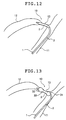
- Fig. 6 is a partial plan view of another embodiment of a balloon catheter comprising the balloon of the present invention. This embodiment will be described, mainly focusing on its differences from the above embodiments and descriptions of the same items are omitted.
- the balloon catheter 1 shown in Fig. 6 is such that the catheter body 2 project from the distal end of the balloon 3 by a predetermined length (for example, about 2 to 100 mm) and the projecting portion 24 is bent at an intermediate position.
- This bending angle ⁇ is not particularly limited but preferably 90° or less, more preferably 15 to 75°, much more preferably 35 to 60°.
- the balloon catheter 1 having the above projecting portion 24 can easily and surely approach the blood vessel which branches off (or bends) at an acute angle like a shunt inosculating portion.
- the bending angle ⁇ of the projecting portion 24 is reduced by the rigidity of the guide wire.
- the projecting portion 24 becomes almost as straight as an arrow.
- the projecting portion 24 is not limited to the crooked shape shown in the figure but may be crooked at multiple locations in different directions.
- the distal end portion of the catheter body 2 is guided by the guide wire inserted into the lumen 23 to position the shrunk (especially deflated and folded) balloon 3 in the stricture 13. This positioning can be carried out easily and surely by providing the marker 6.
- the working fluid is injected into the balloon 3 through the lumen 21 in this state to inflate the balloon 3 gradually.
- the first fixing portion 31 and the second fixing portion 32 of the balloon 3 are contacted tightly to the inner surface of the blood vessel on the proximal end side and distal end side of the stricture 13, respectively, to fix the balloon 3 to the blood vessel. Since the balloon 3 is fixed at both (front and rear) ends of the stricture 13, the fixed balloon 3 does not dislocate in an axial direction.
- the dilation function portion 30 of the balloon 3 is contacted tightly to the stricture 13 and dilates the stricture 13 by pressure.
- the balloon 3 Since the balloon 3 is molded such that it achieves a predetermined shape when it is inflated, a desired balloon 3 is selected to easily control the required expanded diameter of the stricture 13 and proper PTA can be realized.
- the location of the stricture 13, the degree of stricture and an expanded diameter required for the stricture can be known in advance by injecting a contrast medium into a portion near the stricture 13. Therefore, a balloon 3 suitable for these conditions can be easily selected.
- the balloon catheter of the present invention can be inserted into a lumen other than the blood vessel, for example, a digestive canal, trachea, bile duct, urethra, ureter or the like.
- the balloon can be fixed to the stricture without fail when the balloon is inflated and the stricture can be dilated properly and safely.
- the balloon When the balloon is produced by biaxial orientation blow molding, the balloon can be produced with high yield and a balloon having small fluctuations in shape, film strength, characteristics, etc. can be easily produced.
Applications Claiming Priority (2)
| Application Number | Priority Date | Filing Date | Title |
|---|---|---|---|
| JP11180772A JP2001009037A (ja) | 1999-06-25 | 1999-06-25 | 狭窄部拡張用バルーンおよびバルーンカテーテル |
| JP18077299 | 1999-06-25 |
Publications (2)
| Publication Number | Publication Date |
|---|---|
| EP1062966A1 true EP1062966A1 (de) | 2000-12-27 |
| EP1062966B1 EP1062966B1 (de) | 2004-09-01 |
Family
ID=16089066
Family Applications (1)
| Application Number | Title | Priority Date | Filing Date |
|---|---|---|---|
| EP00113074A Expired - Lifetime EP1062966B1 (de) | 1999-06-25 | 2000-06-26 | Ballon zum Aufweiten einer Verengung und Ballonkatheter |
Country Status (4)
| Country | Link |
|---|---|
| EP (1) | EP1062966B1 (de) |
| JP (1) | JP2001009037A (de) |
| AT (1) | ATE274966T1 (de) |
| DE (1) | DE60013362T2 (de) |
Cited By (24)
| Publication number | Priority date | Publication date | Assignee | Title |
|---|---|---|---|---|
| WO2004035127A1 (en) * | 2002-10-15 | 2004-04-29 | Scimed Life Systems, Inc. | Catheter balloon with advantageous cone design |
| WO2006036156A2 (en) | 2004-09-17 | 2006-04-06 | Jang G David | Two-step/dual-diameter balloon angioplasty catheter for bifurcation and side-branch vascular anatomy |
| WO2006068926A1 (en) * | 2004-12-20 | 2006-06-29 | Boston Scientific Limited | Balloon with stepped sections and implements |
| WO2009111712A1 (en) * | 2008-03-06 | 2009-09-11 | Boston Scientific Scimed, Inc. | Balloon catheter devices with folded balloons |
| US7618432B2 (en) | 2003-07-18 | 2009-11-17 | Intervalve, Inc. | Valvuloplasty devices and methods |
| WO2010001404A1 (en) * | 2008-07-02 | 2010-01-07 | Angioslide Ltd. | Balloon catheter system and methods of use thereof |
| US7951111B2 (en) | 2008-10-10 | 2011-05-31 | Intervalve, Inc. | Valvuloplasty catheter and methods |
| WO2011008880A3 (en) * | 2009-07-14 | 2011-07-07 | Apaxis Medical, Inc. | Surgical coring system comprising a balloon catheter |
| US8177743B2 (en) | 1998-05-18 | 2012-05-15 | Boston Scientific Scimed, Inc. | Localized delivery of drug agents |
| US8388574B2 (en) | 2004-04-22 | 2013-03-05 | Angioslide Ltd. | Catheter |
| US8556851B2 (en) | 2005-07-05 | 2013-10-15 | Angioslide Ltd. | Balloon catheter |
| US9168164B2 (en) | 2010-12-01 | 2015-10-27 | C. R. Bard, Inc. | Device to release a self-expanding implant |
| US9242081B2 (en) | 2010-09-13 | 2016-01-26 | Intervalve, Inc. | Positionable valvuloplasty catheter |
| US9387101B2 (en) | 2007-10-17 | 2016-07-12 | C.R. Bard, Inc. | Delivery system for a self-expanding device for placement in a bodily lumen |
| US9675780B2 (en) | 2010-01-19 | 2017-06-13 | Angioslide Ltd. | Balloon catheter system and methods of making and use thereof |
| US9687369B2 (en) | 2009-12-03 | 2017-06-27 | C.R. Bard, Inc. | Stent device delivery system with an outer sheath polymeric reinforcement layer |
| US9687370B2 (en) | 2008-05-09 | 2017-06-27 | C.R. Bard, Inc. | Method of loading a stent into a sheath |
| US9717612B2 (en) | 2009-12-03 | 2017-08-01 | C.R. Bard, Inc. | Stent device delivery system with a varying radial profile pull member |
| US9724216B2 (en) | 2009-12-03 | 2017-08-08 | C. R. Bard, Inc. | Stent device delivery system with inwardly tapering stent bed |
| US9833349B2 (en) | 2008-08-21 | 2017-12-05 | C. R. Bard, Inc. | Method of loading a stent into a sheath |
| US10124153B2 (en) | 2012-12-04 | 2018-11-13 | Angioslide Ltd. | Balloon catheter and methods of use thereof |
| CN109107024A (zh) * | 2018-08-02 | 2019-01-01 | 山东威高集团医用高分子制品股份有限公司 | 狭窄扩张引导器 |
| US10271979B2 (en) | 2008-12-31 | 2019-04-30 | C. R . Bard, Inc. | Stent delivery device with rolling stent retaining sheath |
| US10278845B2 (en) | 2009-12-03 | 2019-05-07 | C. R. Bard, Inc. | Stent device delivery system with a heat shrink resistant support member |
Families Citing this family (9)
| Publication number | Priority date | Publication date | Assignee | Title |
|---|---|---|---|---|
| JP4780543B2 (ja) * | 2001-09-19 | 2011-09-28 | Hoya株式会社 | 内視鏡用バルーン装置 |
| US9439662B2 (en) | 2005-07-05 | 2016-09-13 | Angioslide Ltd. | Balloon catheter |
| EP2259733B1 (de) | 2008-03-06 | 2014-07-23 | Cook Medical Technologies LLC | Medizinische systeme für den zugang in eine innere körperöffnung |
| EP2323569B1 (de) | 2008-05-15 | 2017-10-04 | Cook Medical Technologies LLC | Vorrichtung für den zugang zu einer körperhöhle |
| US8834361B2 (en) | 2009-05-15 | 2014-09-16 | Cook Medical Technologies Llc | Systems, devices and methods for accessing a bodily opening |
| JP6044990B2 (ja) * | 2013-03-29 | 2016-12-14 | 日本ライフライン株式会社 | カテーテル用バルーンおよびバルーンカテーテル |
| EP3329959B1 (de) * | 2015-07-28 | 2020-08-26 | Olympus Corporation | Behandlungsinstrument für endoskop |
| DE102015112390A1 (de) * | 2015-07-29 | 2017-02-02 | Bentley Innomed Gmbh | Ballonkatheter |
| WO2023114368A2 (en) * | 2021-12-17 | 2023-06-22 | Deinde Medical Corp. | Steerable catheters and related methods |
Citations (6)
| Publication number | Priority date | Publication date | Assignee | Title |
|---|---|---|---|---|
| US5055024A (en) * | 1988-10-04 | 1991-10-08 | Cordis Corporation | Apparatus for manufacturing balloons for medical devices |
| US5352199A (en) * | 1993-05-28 | 1994-10-04 | Numed, Inc. | Balloon catheter |
| US5415635A (en) * | 1992-07-21 | 1995-05-16 | Advanced Cardiovascular Systems, Inc. | Balloon assembly with separately inflatable sections |
| WO1997040877A1 (en) * | 1996-05-02 | 1997-11-06 | Cardiovascular Dynamics, Inc. | Focalized intraluminal balloons |
| US5695498A (en) * | 1996-02-28 | 1997-12-09 | Numed, Inc. | Stent implantation system |
| US5749851A (en) * | 1995-03-02 | 1998-05-12 | Scimed Life Systems, Inc. | Stent installation method using balloon catheter having stepped compliance curve |
-
1999
- 1999-06-25 JP JP11180772A patent/JP2001009037A/ja active Pending
-
2000
- 2000-06-26 AT AT00113074T patent/ATE274966T1/de not_active IP Right Cessation
- 2000-06-26 DE DE60013362T patent/DE60013362T2/de not_active Expired - Lifetime
- 2000-06-26 EP EP00113074A patent/EP1062966B1/de not_active Expired - Lifetime
Patent Citations (7)
| Publication number | Priority date | Publication date | Assignee | Title |
|---|---|---|---|---|
| US5055024A (en) * | 1988-10-04 | 1991-10-08 | Cordis Corporation | Apparatus for manufacturing balloons for medical devices |
| US5415635A (en) * | 1992-07-21 | 1995-05-16 | Advanced Cardiovascular Systems, Inc. | Balloon assembly with separately inflatable sections |
| US5352199A (en) * | 1993-05-28 | 1994-10-04 | Numed, Inc. | Balloon catheter |
| US5749851A (en) * | 1995-03-02 | 1998-05-12 | Scimed Life Systems, Inc. | Stent installation method using balloon catheter having stepped compliance curve |
| US5695498A (en) * | 1996-02-28 | 1997-12-09 | Numed, Inc. | Stent implantation system |
| WO1997040877A1 (en) * | 1996-05-02 | 1997-11-06 | Cardiovascular Dynamics, Inc. | Focalized intraluminal balloons |
| US5843116A (en) * | 1996-05-02 | 1998-12-01 | Cardiovascular Dynamics, Inc. | Focalized intraluminal balloons |
Cited By (45)
| Publication number | Priority date | Publication date | Assignee | Title |
|---|---|---|---|---|
| US8262613B2 (en) | 1998-05-18 | 2012-09-11 | Boston Scientific Scimed, Inc. | Localized delivery of drug agents |
| US8177743B2 (en) | 1998-05-18 | 2012-05-15 | Boston Scientific Scimed, Inc. | Localized delivery of drug agents |
| US8574191B2 (en) | 1998-05-18 | 2013-11-05 | Boston Scientific Scimed, Inc. | Localized delivery of drug agents |
| US7226472B2 (en) | 2002-10-15 | 2007-06-05 | Boston Scientific Scimed, Inc. | Catheter balloon with advantageous cone design |
| WO2004035127A1 (en) * | 2002-10-15 | 2004-04-29 | Scimed Life Systems, Inc. | Catheter balloon with advantageous cone design |
| US9375555B2 (en) | 2003-07-18 | 2016-06-28 | Intervalve, Inc. | Valvuloplasty catheter |
| US7618432B2 (en) | 2003-07-18 | 2009-11-17 | Intervalve, Inc. | Valvuloplasty devices and methods |
| US8486102B2 (en) | 2003-07-18 | 2013-07-16 | Intervalve, Inc. | Valvuloplasty catheter |
| US8388574B2 (en) | 2004-04-22 | 2013-03-05 | Angioslide Ltd. | Catheter |
| EP1804866A4 (de) * | 2004-09-17 | 2008-04-02 | G David Jang | Ballon-angioplastiekatheter mit zwei stufen/doppeltem durchmesser für bifurkationen und seitenäste in den gefässen |
| EP1804866A2 (de) * | 2004-09-17 | 2007-07-11 | G. David Jang | Ballon-angioplastiekatheter mit zwei stufen/doppeltem durchmesser für bifurkationen und seitenäste in den gefässen |
| WO2006036156A2 (en) | 2004-09-17 | 2006-04-06 | Jang G David | Two-step/dual-diameter balloon angioplasty catheter for bifurcation and side-branch vascular anatomy |
| US7879053B2 (en) | 2004-12-20 | 2011-02-01 | Boston Scientific Scimed, Inc. | Balloon with stepped sections and implements |
| WO2006068926A1 (en) * | 2004-12-20 | 2006-06-29 | Boston Scientific Limited | Balloon with stepped sections and implements |
| US8556851B2 (en) | 2005-07-05 | 2013-10-15 | Angioslide Ltd. | Balloon catheter |
| US8894680B2 (en) | 2005-10-14 | 2014-11-25 | Angioslide Ltd. | Balloon catheter |
| US9782570B2 (en) | 2005-10-14 | 2017-10-10 | Angioslide Ltd. | Balloon catheter |
| US9387101B2 (en) | 2007-10-17 | 2016-07-12 | C.R. Bard, Inc. | Delivery system for a self-expanding device for placement in a bodily lumen |
| WO2009111712A1 (en) * | 2008-03-06 | 2009-09-11 | Boston Scientific Scimed, Inc. | Balloon catheter devices with folded balloons |
| US8114049B2 (en) | 2008-03-06 | 2012-02-14 | Boston Scientific Scimed, Inc. | Balloon catheter devices with folded balloons |
| US9687370B2 (en) | 2008-05-09 | 2017-06-27 | C.R. Bard, Inc. | Method of loading a stent into a sheath |
| US8827951B2 (en) | 2008-07-02 | 2014-09-09 | Doron Besser | Balloon catheter system and methods of use thereof |
| CN102131471A (zh) * | 2008-07-02 | 2011-07-20 | 安乔斯里德公司 | 囊导管系统及其使用方法 |
| WO2010001404A1 (en) * | 2008-07-02 | 2010-01-07 | Angioslide Ltd. | Balloon catheter system and methods of use thereof |
| US9833349B2 (en) | 2008-08-21 | 2017-12-05 | C. R. Bard, Inc. | Method of loading a stent into a sheath |
| US8900264B2 (en) | 2008-10-10 | 2014-12-02 | Intervalve, Inc. | Valvuloplasty catheter and methods |
| US7951111B2 (en) | 2008-10-10 | 2011-05-31 | Intervalve, Inc. | Valvuloplasty catheter and methods |
| US9504807B2 (en) | 2008-10-10 | 2016-11-29 | Intervalve, Inc. | Valvuloplasty catheter and methods |
| US10271979B2 (en) | 2008-12-31 | 2019-04-30 | C. R . Bard, Inc. | Stent delivery device with rolling stent retaining sheath |
| WO2011008880A3 (en) * | 2009-07-14 | 2011-07-07 | Apaxis Medical, Inc. | Surgical coring system comprising a balloon catheter |
| US10555824B2 (en) | 2009-12-03 | 2020-02-11 | C. R. Bard, Inc. | Stent device delivery system with inwardly tapering stent bed |
| US10278845B2 (en) | 2009-12-03 | 2019-05-07 | C. R. Bard, Inc. | Stent device delivery system with a heat shrink resistant support member |
| US9724216B2 (en) | 2009-12-03 | 2017-08-08 | C. R. Bard, Inc. | Stent device delivery system with inwardly tapering stent bed |
| US10779975B2 (en) | 2009-12-03 | 2020-09-22 | C. R. Bard, Inc. | Stent device delivery system with a varying radial profile pull member |
| US9687369B2 (en) | 2009-12-03 | 2017-06-27 | C.R. Bard, Inc. | Stent device delivery system with an outer sheath polymeric reinforcement layer |
| US10449072B2 (en) | 2009-12-03 | 2019-10-22 | C.R. Bard, Inc. | Stent device delivery system with an outer sheath polymeric reinforcement layer |
| US9717612B2 (en) | 2009-12-03 | 2017-08-01 | C.R. Bard, Inc. | Stent device delivery system with a varying radial profile pull member |
| US9675780B2 (en) | 2010-01-19 | 2017-06-13 | Angioslide Ltd. | Balloon catheter system and methods of making and use thereof |
| US9242081B2 (en) | 2010-09-13 | 2016-01-26 | Intervalve, Inc. | Positionable valvuloplasty catheter |
| US10245419B2 (en) | 2010-09-13 | 2019-04-02 | Intervalve Medical, Inc. | Positionable valvuloplasty catheter |
| US9168164B2 (en) | 2010-12-01 | 2015-10-27 | C. R. Bard, Inc. | Device to release a self-expanding implant |
| US10821013B2 (en) | 2010-12-01 | 2020-11-03 | C. R. Bard, Inc. | Device to release a self-expanding implant |
| US10124153B2 (en) | 2012-12-04 | 2018-11-13 | Angioslide Ltd. | Balloon catheter and methods of use thereof |
| CN109107024A (zh) * | 2018-08-02 | 2019-01-01 | 山东威高集团医用高分子制品股份有限公司 | 狭窄扩张引导器 |
| CN109107024B (zh) * | 2018-08-02 | 2024-04-16 | 山东威高集团医用高分子制品股份有限公司 | 狭窄扩张引导器 |
Also Published As
| Publication number | Publication date |
|---|---|
| EP1062966B1 (de) | 2004-09-01 |
| ATE274966T1 (de) | 2004-09-15 |
| JP2001009037A (ja) | 2001-01-16 |
| DE60013362D1 (de) | 2004-10-07 |
| DE60013362T2 (de) | 2005-09-08 |
Similar Documents
| Publication | Publication Date | Title |
|---|---|---|
| EP1062966B1 (de) | Ballon zum Aufweiten einer Verengung und Ballonkatheter | |
| US5876426A (en) | System and method of providing a blood-free interface for intravascular light delivery | |
| EP0669143B1 (de) | Ballondilationskatheter mit variablem Durchmesser | |
| US6402778B2 (en) | Stent installation method using balloon catheter having stepped compliance curve | |
| US6966889B2 (en) | Multi-lumen catheters and methods for using same | |
| EP1990069B1 (de) | Katheteranordnung | |
| US5549551A (en) | Adjustable length balloon catheter | |
| EP2474336B1 (de) | Hochfester und hochflexibler Ballonkatheterschaft und Herstellungsverfahren | |
| US6126634A (en) | Balloon assembly with separately inflatable sections | |
| US5569195A (en) | Medical balloon and method of making same | |
| US6312374B1 (en) | Radioactive wire placement catheter | |
| US7314364B2 (en) | Slotted mold for making a balloon catheter | |
| JPS63238875A (ja) | 膨張カテーテル | |
| US20020120321A1 (en) | Stent retention mechanism | |
| US20040039409A1 (en) | Convertible balloon catheter and manufacture thereof | |
| US20170095647A1 (en) | Reduced material tip for catheter and method of forming same | |
| US20090254113A1 (en) | Dilatation balloon with ridges and methods | |
| CN100515514C (zh) | 经皮的冠状动脉腔内血管成形术和/或经皮的腔内血管成形术的囊体 | |
| US8518103B2 (en) | Bifurcated delivery system and method | |
| US6712833B1 (en) | Method of making a catheter balloon | |
| JP4397072B2 (ja) | 螺旋状バルーンカテーテル及びその製造方法 | |
| JPH07112029A (ja) | 医療用バルーン | |
| JP2001029475A (ja) | 血液灌流バルーンカテーテル | |
| JP2001046532A (ja) | 放射線照射カテーテル | |
| JP2001009045A (ja) | センターリング用カテーテルシステム |
Legal Events
| Date | Code | Title | Description |
|---|---|---|---|
| PUAI | Public reference made under article 153(3) epc to a published international application that has entered the european phase |
Free format text: ORIGINAL CODE: 0009012 |
|
| AK | Designated contracting states |
Kind code of ref document: A1 Designated state(s): AT BE CH CY DE DK ES FI FR GB GR IE IT LI LU MC NL PT SE |
|
| AX | Request for extension of the european patent |
Free format text: AL;LT;LV;MK;RO;SI |
|
| 17P | Request for examination filed |
Effective date: 20010327 |
|
| AKX | Designation fees paid |
Free format text: AT BE CH CY DE DK ES FI FR GB GR IE IT LI LU MC NL PT SE |
|
| 17Q | First examination report despatched |
Effective date: 20030718 |
|
| GRAP | Despatch of communication of intention to grant a patent |
Free format text: ORIGINAL CODE: EPIDOSNIGR1 |
|
| GRAS | Grant fee paid |
Free format text: ORIGINAL CODE: EPIDOSNIGR3 |
|
| GRAA | (expected) grant |
Free format text: ORIGINAL CODE: 0009210 |
|
| AK | Designated contracting states |
Kind code of ref document: B1 Designated state(s): AT BE CH CY DE DK ES FI FR GB GR IE IT LI LU MC NL PT SE |
|
| PG25 | Lapsed in a contracting state [announced via postgrant information from national office to epo] |
Ref country code: BE Free format text: LAPSE BECAUSE OF FAILURE TO SUBMIT A TRANSLATION OF THE DESCRIPTION OR TO PAY THE FEE WITHIN THE PRESCRIBED TIME-LIMIT Effective date: 20040901 Ref country code: LI Free format text: LAPSE BECAUSE OF FAILURE TO SUBMIT A TRANSLATION OF THE DESCRIPTION OR TO PAY THE FEE WITHIN THE PRESCRIBED TIME-LIMIT Effective date: 20040901 Ref country code: AT Free format text: LAPSE BECAUSE OF FAILURE TO SUBMIT A TRANSLATION OF THE DESCRIPTION OR TO PAY THE FEE WITHIN THE PRESCRIBED TIME-LIMIT Effective date: 20040901 Ref country code: FI Free format text: LAPSE BECAUSE OF FAILURE TO SUBMIT A TRANSLATION OF THE DESCRIPTION OR TO PAY THE FEE WITHIN THE PRESCRIBED TIME-LIMIT Effective date: 20040901 Ref country code: CH Free format text: LAPSE BECAUSE OF FAILURE TO SUBMIT A TRANSLATION OF THE DESCRIPTION OR TO PAY THE FEE WITHIN THE PRESCRIBED TIME-LIMIT Effective date: 20040901 |
|
| REG | Reference to a national code |
Ref country code: GB Ref legal event code: FG4D |
|
| REG | Reference to a national code |
Ref country code: CH Ref legal event code: EP |
|
| REG | Reference to a national code |
Ref country code: IE Ref legal event code: FG4D |
|
| REF | Corresponds to: |
Ref document number: 60013362 Country of ref document: DE Date of ref document: 20041007 Kind code of ref document: P |
|
| PG25 | Lapsed in a contracting state [announced via postgrant information from national office to epo] |
Ref country code: SE Free format text: LAPSE BECAUSE OF FAILURE TO SUBMIT A TRANSLATION OF THE DESCRIPTION OR TO PAY THE FEE WITHIN THE PRESCRIBED TIME-LIMIT Effective date: 20041201 Ref country code: GR Free format text: LAPSE BECAUSE OF FAILURE TO SUBMIT A TRANSLATION OF THE DESCRIPTION OR TO PAY THE FEE WITHIN THE PRESCRIBED TIME-LIMIT Effective date: 20041201 Ref country code: DK Free format text: LAPSE BECAUSE OF FAILURE TO SUBMIT A TRANSLATION OF THE DESCRIPTION OR TO PAY THE FEE WITHIN THE PRESCRIBED TIME-LIMIT Effective date: 20041201 |
|
| PG25 | Lapsed in a contracting state [announced via postgrant information from national office to epo] |
Ref country code: ES Free format text: LAPSE BECAUSE OF FAILURE TO SUBMIT A TRANSLATION OF THE DESCRIPTION OR TO PAY THE FEE WITHIN THE PRESCRIBED TIME-LIMIT Effective date: 20041212 |
|
| REG | Reference to a national code |
Ref country code: CH Ref legal event code: PL |
|
| ET | Fr: translation filed | ||
| PG25 | Lapsed in a contracting state [announced via postgrant information from national office to epo] |
Ref country code: CY Free format text: LAPSE BECAUSE OF FAILURE TO SUBMIT A TRANSLATION OF THE DESCRIPTION OR TO PAY THE FEE WITHIN THE PRESCRIBED TIME-LIMIT Effective date: 20050626 Ref country code: LU Free format text: LAPSE BECAUSE OF NON-PAYMENT OF DUE FEES Effective date: 20050626 |
|
| PG25 | Lapsed in a contracting state [announced via postgrant information from national office to epo] |
Ref country code: MC Free format text: LAPSE BECAUSE OF NON-PAYMENT OF DUE FEES Effective date: 20050630 |
|
| PLBE | No opposition filed within time limit |
Free format text: ORIGINAL CODE: 0009261 |
|
| STAA | Information on the status of an ep patent application or granted ep patent |
Free format text: STATUS: NO OPPOSITION FILED WITHIN TIME LIMIT |
|
| 26N | No opposition filed |
Effective date: 20050602 |
|
| PG25 | Lapsed in a contracting state [announced via postgrant information from national office to epo] |
Ref country code: PT Free format text: LAPSE BECAUSE OF NON-PAYMENT OF DUE FEES Effective date: 20050201 |
|
| PGFP | Annual fee paid to national office [announced via postgrant information from national office to epo] |
Ref country code: NL Payment date: 20120626 Year of fee payment: 13 Ref country code: IE Payment date: 20120619 Year of fee payment: 13 |
|
| REG | Reference to a national code |
Ref country code: NL Ref legal event code: V1 Effective date: 20140101 |
|
| REG | Reference to a national code |
Ref country code: IE Ref legal event code: MM4A |
|
| PG25 | Lapsed in a contracting state [announced via postgrant information from national office to epo] |
Ref country code: IE Free format text: LAPSE BECAUSE OF NON-PAYMENT OF DUE FEES Effective date: 20130626 Ref country code: NL Free format text: LAPSE BECAUSE OF NON-PAYMENT OF DUE FEES Effective date: 20140101 |
|
| REG | Reference to a national code |
Ref country code: FR Ref legal event code: PLFP Year of fee payment: 17 |
|
| REG | Reference to a national code |
Ref country code: FR Ref legal event code: PLFP Year of fee payment: 18 |
|
| REG | Reference to a national code |
Ref country code: FR Ref legal event code: PLFP Year of fee payment: 19 |
|
| PGFP | Annual fee paid to national office [announced via postgrant information from national office to epo] |
Ref country code: DE Payment date: 20180612 Year of fee payment: 19 |
|
| PGFP | Annual fee paid to national office [announced via postgrant information from national office to epo] |
Ref country code: FR Payment date: 20180511 Year of fee payment: 19 |
|
| PGFP | Annual fee paid to national office [announced via postgrant information from national office to epo] |
Ref country code: IT Payment date: 20180625 Year of fee payment: 19 Ref country code: GB Payment date: 20180620 Year of fee payment: 19 |
|
| REG | Reference to a national code |
Ref country code: DE Ref legal event code: R119 Ref document number: 60013362 Country of ref document: DE |
|
| GBPC | Gb: european patent ceased through non-payment of renewal fee |
Effective date: 20190626 |
|
| PG25 | Lapsed in a contracting state [announced via postgrant information from national office to epo] |
Ref country code: DE Free format text: LAPSE BECAUSE OF NON-PAYMENT OF DUE FEES Effective date: 20200101 Ref country code: GB Free format text: LAPSE BECAUSE OF NON-PAYMENT OF DUE FEES Effective date: 20190626 Ref country code: IT Free format text: LAPSE BECAUSE OF NON-PAYMENT OF DUE FEES Effective date: 20190626 |
|
| PG25 | Lapsed in a contracting state [announced via postgrant information from national office to epo] |
Ref country code: FR Free format text: LAPSE BECAUSE OF NON-PAYMENT OF DUE FEES Effective date: 20190630 |