EP1061256A2 - Kolben für Taumelscheibenkompressor mit mittels Gleitfläche verbundenem Kopf und Stange - Google Patents
Kolben für Taumelscheibenkompressor mit mittels Gleitfläche verbundenem Kopf und Stange Download PDFInfo
- Publication number
- EP1061256A2 EP1061256A2 EP00112606A EP00112606A EP1061256A2 EP 1061256 A2 EP1061256 A2 EP 1061256A2 EP 00112606 A EP00112606 A EP 00112606A EP 00112606 A EP00112606 A EP 00112606A EP 1061256 A2 EP1061256 A2 EP 1061256A2
- Authority
- EP
- European Patent Office
- Prior art keywords
- piston
- swash plate
- cylinder block
- sliding
- head
- Prior art date
- Legal status (The legal status is an assumption and is not a legal conclusion. Google has not performed a legal analysis and makes no representation as to the accuracy of the status listed.)
- Withdrawn
Links
Images


Classifications
-
- F—MECHANICAL ENGINEERING; LIGHTING; HEATING; WEAPONS; BLASTING
- F04—POSITIVE - DISPLACEMENT MACHINES FOR LIQUIDS; PUMPS FOR LIQUIDS OR ELASTIC FLUIDS
- F04B—POSITIVE-DISPLACEMENT MACHINES FOR LIQUIDS; PUMPS
- F04B27/00—Multi-cylinder pumps specially adapted for elastic fluids and characterised by number or arrangement of cylinders
- F04B27/08—Multi-cylinder pumps specially adapted for elastic fluids and characterised by number or arrangement of cylinders having cylinders coaxial with, or parallel or inclined to, main shaft axis
- F04B27/0873—Component parts, e.g. sealings; Manufacturing or assembly thereof
- F04B27/0878—Pistons
Definitions
- the present invention relates to a piston used for a swash plate type compressor.
- pistons for a swash plate type compressor there are known various types of pistons each of which has (a) a head portion which is slidably fitted in a cylinder bore formed in a cylinder block, (b) a neck portion which engages a swash plate, and (c) a connecting portion which connects the head portion and the neck portion.
- An example of such pistons is disclosed in JP-A-9-203378.
- the head portion has a through-hole formed therethrough in a direction substantially parallel to the circumferential direction of the cylinder block, and the head portion and the neck portion are connected to each other at two circumferential portions of the cylinder bore which correspond to respective radially inner and outer portions of the cylinder block.
- the through-hole formed in the head portion contributes to a reduction in the weight of the piston.
- This object may be achieved by a piston for a swash plate type compressor, which is constructed according to any one of the following forms or modes of the present invention, each of which is numbered like the appended claims and depends from the other form or forms, where appropriate, to indicate and clarify possible combinations of technical features of the present invention, for easier understanding of the invention.
- the present invention is not limited to the technical features and their combinations described below. It is also to be understood that any technical feature described below in combination with other technical features may be a subject matter of the present invention, independently of those other technical features.
- FIG. 1 shows the swash plate type compressor incorporating a plurality of pistons.
- reference numeral 10 denotes a cylinder block having a centerline M and a plurality of cylinder bores 12 formed so as to extend in its axial direction such that the cylinder bores are arranged along a circle whose center lies on the centerline M.
- the piston generally indicated at 14 is reciprocably received in each of the cylinder bores 12.
- a front housing 16 To one of the axially opposite end faces (the right end face as seen in Fig. 1, which will be referred to as "front end face"), there is attached a front housing 16.
- front housing 18 To the other end face (the left end face as seen in Fig. 1, which will be referred to as "rear end face"), there is attached a rear housing 18 through a valve plate structure 20.
- the front housing 16, rear housing 18 and cylinder block 10 cooperate to constitute a major portion of the body of the swash plate type compressor.
- the rear housing 18 and the valve plate 20 cooperate to define a suction chamber 22 and a discharge chamber 24, which are connected to a refrigerating circuit (not shown) through an inlet 26 and an outlet 28, respectively.
- the valve plate structure 20 has a suction ports 40, suction valves 42, discharge ports 46 and discharge valves 48.
- a rotary drive shaft 50 is disposed in the cylinder block 10 and the front housing 16 such that the axis rotation of the drive shaft 50 is aligned with the centerline M of the cylinder block 10.
- the drive shaft 50 are supported at its opposite end portions by the front housing 16 and the cylinder block 10 via respective bearings.
- the cylinder block 10 has a central bearing hole 56 formed in a central portion thereof, and the bearing is disposed in this central bearing hole, for supporting the drive shaft 50 at its rear end portion.
- the rotary drive shaft 50 carries a swash plate 60 mounted thereon such that the swash plate 60 is axially movable and tiltable relative to the drive shaft 50.
- a lug plate 62 which is held in engagement with the swash plate 60 through a hinge mechanism 64.
- the lug plate 62 is rotatable with the drive shaft 50 relative to the front housing 16 through a thrust bearing 66.
- the hinge mechanism 64 causes the swash plate 60 to be rotated with the drive shaft 50 during rotation of the drive shaft 50, and guides the swash plate 60 for its axial and tilting motions.
- the hinge mechanism 64 includes a pair of support arms 70 fixed to the lug plate 62, and guide pins 72 formed on the swash plate 60.
- the guide pins 72 slidably encage guide holes 74 formed in the support arms 70.
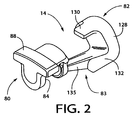
- the piston 14 indicated above includes a neck portion 80 engaging the swash plate 60, a head portion 82 fitted in the corresponding cylinder bore 12, and a connecting portion 83 connecting the neck and head portions 80, 82.
- the neck portion 80 has a groove 84 formed therein, and the swash plate 60 is held in engagement with the groove 84 through a pair of hemi-spherical shoes 86.
- the hemi-spherical shoes 86 are held in the groove 84 at their hemi-spherical surfaces such that the shoes 86 slidably engage the neck portion 80 at their hemi-spherical surfaces, and slidably engage the opposite surfaces of the swash plate 60 at their flat surfaces.
- piston 14 is a single-headed piston.
- the head portion 82 of the piston 14 cooperates with the cylinder block 10 and the valve plate structure 20 to define a pressurizing chamber 87.
- the configuration of the piston 14 will be described in detail.
- a rotary motion of the swash plate 60 is converted into a reciprocating linear motion of the piston 14 through the shoes 86.
- a refrigerant gas in the suction chamber 22 is sucked or admitted into the pressurizing chamber 87 through the suction port 40 and the suction valve 42, when the piston 14 is moved from its upper dead point to its lower dead point, that is, when the piston 14 is in the suction stroke.
- the refrigerant gas in the pressurizing chamber 87 is pressurized by the piston 14 when the piston 14 is moved from its lower dead point to its upper dead point, that is, when the piston 14 is in the compression stroke.
- the thus pressurized refrigerant gas is delivered into the discharge chamber 24 through the discharge port 46 and the discharge valve 48.
- a reaction force acts on the piston 14 in the axial direction as a result of compression of the refrigerant gas in the pressurizing chamber 87.
- This compression reaction force is received by the front housing 16 through the piston 14, swash plate 60, lug plate 62 and the thrust bearing 66.
- the neck portion 80 of the piston 14 has an integrally formed rotation preventive portion 88, which is arranged to contact the inner circumferential surface of the front housing 16, for thereby preventing a rotary motion of the piston 14 about its centerline N (Fig. 1).
- the cylinder block 10 has an intake passage 94 formed therethrough for communication between the discharge chamber 24 and a crank chamber 96 which is defined between the front housing 16 and the cylinder block 10.
- the intake passage 94 is connected to a solenoid-operated control valve 100 provided to control the pressure in the crank chamber 96.
- the solenoid-operated control valve 100 includes a solenoid coil 102, and a shut-off valve 104 which is selectively closed and opened by energization and de-energization of the solenoid coil 102. Namely, the shut-off valve 104 is placed in its closed state when the solenoid coil 102 is energized, and is placed in its open state when the coil 102 is de-energized.
- the rotary drive shaft 50 has a bleeding passage 110 formed therethrough.
- the bleeding passage 110 is open at one of its opposite ends to the central support hole 56 indicated above, and is open to the crank chamber 96 through a communication passage 112.
- the central support hole 56 communicates at its bottom with the suction chamber 22 through a communication port 114.
- the intake passage 94 is opened, permitting the pressurized refrigerant gas to be delivered from the discharge chamber 24 into the crank chamber 96, resulting in an increase in the pressure in the crank chamber 96, and the angle of inclination of the swash plate 60 is reduced, so that the discharge capacity of the compressor is accordingly reduced.
- the maximum angle of inclination of the swash plate 60 is limited by abutting contact of a stop 120 formed on the swash plate 60, with the lug plate 62, and the minimum angle of inclination of the swash plate 60 is limited by abutting contact of the swash plate 60 with a stop 122 in the form of a ring fixed to the drive shaft 50.
- the pressure in the crank chamber 96 is controlled by controlling the solenoid-operated control valve 100 to selectively connect and disconnect the crank chamber 96 to and from the discharge chamber 24.
- the angle of inclination of the swash plate 60 is changed with a change in the pressure in the crank chamber 96, so that the stroke of the piston 14 is controlled to control the discharge capacity of the compressor.
- the swash plate type compressor having the piston 14 in each cylinder bore 12 is of a variable capacity type.
- the solenoid coil 102 of the solenoid-operated control valve 100 is controlled by a control device (not shown) depending upon a load acting on the air conditioning system including the present compressor.
- the control device is principally constituted by a computer.
- the cylinder block 10 and each piston 14 are formed of an aluminum alloy.
- the piston 14 is coated at its outer circumferential surface with a fluoro resin film, which prevents a direct contact of the aluminum alloy of the piston 14 with the aluminum alloy of the cylinder block 10, and makes it possible to minimize the amount of clearance between the piston 14 and the cylinder bore 12.
- the cylinder block 10 and the piston 14 may also be formed of a hyper-eutectic aluminum silicon alloy. Other materials may be used for the cylinder block 10 and the piston 14.
- the head portion 83 of the piston 14 includes a body portion 128, and an outer sliding projection 130 and an inner sliding projection 132 which correspond to respective radially outer and inner portions of the cylinder block 10.
- the body portion 128 has a circular shape in cross section.
- the outer and inner sliding projections 130, 132 project toward the neck portion 80 from respective circumferential parts of the circular body portion 128, which parts correspond to the radially outer and inner portions of the cylinder block 10.
- the outer and inner sliding projections 130, 132 are adapted to slide on the respective circumferential portions of the inner circumferential surface of the cylinder bore 12, which portions correspond to the radially outer and inner portions of the cylinder block 10.
- the inner sliding projection 132 which has a sliding surface 133, is located at the circumferential portion of the piston 14 in which the groove 84 formed in the neck portion 80 is open.
- This circumferential portion of the piston 14 will be referred to as “radially inner circumferential portion”, and the circumferential portion of the piston 14 diametrically opposite to the radially inner circumferential portion will be referred to as “radially outer circumferential portion”.
- the connecting portion 82 of the piston 14 includes a rib 135 connecting the inner sliding projection 132 and the neck portion 80. Namely, the head portion 82 and the neck portion 80 are connected to each other by the connecting portion 83 at the radially inner circumferential portion of the piston 14, but are not connected to each other at the other circumferential portions of the piston 14 including the radially outer circumferential portion. This arrangement permits a considerable reduction in the weight of the piston 14.
- the head portion 82 and the neck portion 80 need not be connected to each other at both of the radially inner and outer circumferential portions of the piston 14.
- the elimination of the connecting portion 83 at the radially outer circumferential portion of the piston 14 is effective to reduce the weight of the piston 14. This elimination may require an increase in the weight of the connecting portion 83 at the radially inner circumferential portion of the piston 14, to obtain the required strength of the connecting portion 83.
- the provision of the connecting portion 83 at the radially inner circumferential portion only permits a reduced weight of the piston 14, as compared with the provision of the connecting portion at both of the radially inner and outer circumferential portions.
- the rib 135 is inclined with respect to the centerline N of the piston 14, in order to increase the strength of the connecting portion 83.
- the rib 135 is formed so as to extend generally in the direction in which the piston 14 receives a reaction force from the swash plate 60, rather than in the direction parallel to the centerline N, so that the strength of the connecting portion 83 is effectively increased.
- the inner sliding projection 132 is configured such that the sliding surface 133 of the projection 132 is symmetrical with respect to a plane which includes the centerline N of the piston 14 and the centerline M of the cylinder block 10 (axis of rotation M of the drive shaft 50).
- This configuration permits the inner sliding projection 132 to receive the reaction force from the cylinder bore 12 over a sufficiently large surface area, irrespective whether the drive shaft 50 is rotated in the clockwise or counterclockwise direction. Accordingly, the instant configuration is effective to minimize a local wear of the inner sliding projection 132 and the cylinder bore 12.
- the weight of the inner sliding projection 132 may be reduced at its trailing portion as seen in the rotating direction of the drive shaft 50, in order to reduce the weight of the piston 14.
- the piston 14 can be used for only a swash plate type compressor wherein the drive shaft 50 is always rotated in the predetermined direction.
- the present piston 14 can be used irrespective of the direction of rotation of the drive shaft 50.
- piston 14 is not limited to that described above, and may be designed otherwise.
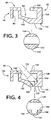
- pistons 140, 160 and 170 as shown in Figs. 4, 5 and 6 are provided according to other embodiments of this invention.
- the inner sliding projection 132 has a recess 144 in an inner surface 142 thereof which faces in the radially outward direction of the cylinder block 10 and which is opposed to the outer sliding projection 130.
- an opening 146 is provided between the outer sliding projection 130 and the neck portion 80, which are not connected by the connecting portion including the rib 135.
- the inner surface 142 can be easily accessed through the opening 146 when the recess 144 is formed in the inner surface 142.
- the recess 144 is formed by a cutting operation using a cutting tool 152 such as an end mill, with the cutting tool 152 extending through the opening 146, after the casting of the piston 14. Described in detail, the rotating cutting tool 152 extending through the opening 146 and the piston 14 are fed relative to each other, with the cutting edge of the tool 152 being held in contact with the inner surface 142. In the present embodiment, the rotating end mill 152 is fed relative to the inner surface 142. The provision of the recess 144 provides a further reduction in the weight of the piston 14.
- the recess 142 also functions as an oil reservoir.
- a lubricating oil distributed in the crank chamber 96 is accumulated in the oil reservoir 144, and is splashed upon reciprocating motion of the piston 14, to lubricate the contacting surfaces of the piston 14 and the cylinder bore 12, and the contacting surfaces of the piston 14 and the swash plate 60, so that the sliding resistance of the piston 14 is effectively reduced for smooth sliding motion of the piston 14.
- the piston 140 may be produced by casting with the recess 144 formed in the inner surface 142.
- a slide core used for forming the recess 144 during casting of the piston 140 can be easily set in a casting mold, through an opening of the mold corresponding to the opening 146.
- the single recess 144 is formed in the inner surface 142
- a plurality of recesses may be formed in the inner surface 142.
- the at least one recess formed in the surface 142 may be shaped and dimensioned as desired.
- the total volume of the at least one recess is desirably maximized to such an extent that assures the sufficient strength of the piston 14.
- At least one recess may also be formed in an inner surface 150 of the body portion 128 which faces toward the neck portion 80.
- the provision of the recesses in both of the inner surfaces 142, 150 provides a further reduction in the weight of the piston 14.
- the inner surface 150 rather than the inner surface 142 may have at least one recess.
- a recess in the form of a hole 164 is formed, with a suitable cutting tool such as a drill, in the inner sliding projection 132 and the body portion 128, such that the hole 164 is open in the side of an outer sliding surface 162 of the inner sliding projection 132 which slidably contacts the inner circumferential surface of the cylinder bore 12.
- the hole 164 is formed obliquely with the cutting tool being fed through the inner sliding projection 132 until the cutting tip of the tool reaches a midpoint of the thickness of the body portion 128.
- the hole 164 is open in the outer sliding surface 162 of the inner sliding projection 132, a fluid-tight sealing is provided between the sliding surface of the body portion 128 and the inner circumferential surface of the cylinder bore 12.
- the hole 164 may be formed at any part of the inner sliding projection 132, it is desirable to form the hole 164 at a part at which the reaction force received by the projection 132 is not so large.
- the reaction force is relatively large at the end portion of the projection 132 on the side of the neck portion 80, and at the circumferential portion of the projection 132 which is on the leading side of the plane including the centerlines N and M of the piston 160 and cylinder block 10, as seen in the rotating direction of the drive shaft 50.
- the hole 164 is preferably located at a portion of the projection 132 other than the above-indicated portion at which the reaction force is relatively large.
- the hole 164 is formed through an intermediate portion of the projection 132 (open in an intermediate portion of the sliding surface 162), as viewed in the axial direction of the drive shaft 50.
- the hole 164 may be formed by feeding a rotating drill through the projection 132 and the body portion 128 of the stationary piston 160, such that the hole 164 is open in the sliding surface 162.
- the hole 164 extending through the inner sliding projection 132 need not reach the body portion 128. Further, a plurality of holes may be formed, provided none of the holes are located at the above-identified end portion of the projection 132 at which the reaction force is relatively large. In any case, at least one hole is effective to reduce the weight of the piston 160. It is also noted that at least one recess is formed in at least one of the inner surfaces 142, 150, while at the same time at least one recess is formed in the outer sliding surface 162. For instance, the recess 144 shown in Fig. 4 is formed in the inner surface 142 while the hole 164 shown in Fig. 5 is formed in the outer sliding surface 162. In this case, the weight of the piston can be further reduced.
- At least one recess may be formed in at least one of the inner surfaces 142, 150 and outer sliding surface 162, in the piston 14 of Fig. 3 and any other piston having a rib which connect the head portion 82 and the neck portion 80 at the radially inner circumferential portion of the piston.
- the piston 170 of Fig. 6 has a wall 172 which extends in the radial direction of the drive shaft 50.
- the wall 172 is provided between the outer and inner sliding projections 130, 132.
- the wall 172 connects the outer and inner sliding projections 130, 132, for increasing the strength of the piston 170 and thereby minimizing a local wear of the piston 170.
- the wall 172 may be formed so as to extend in a direction intersecting the circumferential direction of the circular body portion 128.
- the inner sliding projection 132 has two recesses 176 in an inner surface 174 thereof which is opposed to the outer sliding projection 130.
- the two recesses 176 are located on the respective opposite sides of the wall 172.
- Each recess 176 may be formed in the same manner as in the second embodiment.
- the recesses 176 function as an oil reservoir.
- the piston 170 may have a plurality of walls 172 to further increase its strength. It is noted that at least one wall 172 need not connect the outer and inner sliding projections 130, 132. For instance, the wall 172 may extend from the inner sliding projection 132 toward the outer sliding projection 130, or alternatively, from the outer sliding projection 130 toward the inner sliding projection 132.
- the construction of the swash plate type compressor for which the piston 14, 140, 160, 170 is incorporated is not limited to that of Fig. 1.
- the solenoid-operated control valve 100 is not essential, and the compressor may use a shut-off valve which is opened and closed on the basis of a difference between the pressures in the crank chamber 96 and the suction chamber 24.
- the control valve 100 or the shut-off valve permits an increase in the discharge capacity of the compressor with a decrease in the pressure in the crank chamber 96 which causes an increase in the angle of inclination of the swash plate 60.
- a piston for a swash plate type compressor including a head portion (82) slidably fitted in a cylinder bore (12) in a cylinder block (10) of the compressor, a neck portion (80) slidably engaging a swash plate (60) of the compressor, and a connecting portion (83) connecting the head and neck portions, wherein the head portion (82) comprises a circular body portion (128), and an inner sliding projection (132) extending toward the neck portion (80) from a radially inner circumferential part of the body portion which corresponds to a radially inner portion of the cylinder block (10).
- the inner sliding projection has a sliding surface (133, 162) for sliding contact with an inner circumferential surface of the cylinder bore.
- the sliding surface is symmetrical with respect to a plane including centerlines (N, M) of the piston (14, 140, 160, 170) and the cylinder block.
- the connecting portion (83) connects the inner sliding projection and the neck portion.
Landscapes
- Engineering & Computer Science (AREA)
- Manufacturing & Machinery (AREA)
- Mechanical Engineering (AREA)
- General Engineering & Computer Science (AREA)
- Compressors, Vaccum Pumps And Other Relevant Systems (AREA)
- Transmission Devices (AREA)
- Compressor (AREA)
Applications Claiming Priority (2)
| Application Number | Priority Date | Filing Date | Title |
|---|---|---|---|
| JP11168591A JP2000356185A (ja) | 1999-06-15 | 1999-06-15 | 斜板式圧縮機用ピストン |
| JP16859199 | 1999-06-15 |
Publications (2)
| Publication Number | Publication Date |
|---|---|
| EP1061256A2 true EP1061256A2 (de) | 2000-12-20 |
| EP1061256A3 EP1061256A3 (de) | 2001-05-09 |
Family
ID=15870903
Family Applications (1)
| Application Number | Title | Priority Date | Filing Date |
|---|---|---|---|
| EP00112606A Withdrawn EP1061256A3 (de) | 1999-06-15 | 2000-06-14 | Kolben für Taumelscheibenkompressor mit mittels Gleitfläche verbundenem Kopf und Stange |
Country Status (3)
| Country | Link |
|---|---|
| US (1) | US6332394B1 (de) |
| EP (1) | EP1061256A3 (de) |
| JP (1) | JP2000356185A (de) |
Families Citing this family (5)
| Publication number | Priority date | Publication date | Assignee | Title |
|---|---|---|---|---|
| JP2001153046A (ja) * | 1999-12-01 | 2001-06-05 | Toyota Autom Loom Works Ltd | 圧縮機用ピストン製造方法及びピストン製造装置 |
| KR100779068B1 (ko) * | 2001-08-10 | 2007-11-27 | 한라공조주식회사 | 사판식 압축기 |
| JP2003139052A (ja) * | 2001-11-05 | 2003-05-14 | Toyota Industries Corp | 圧縮機用のピストン及びその製造方法 |
| JP4194350B2 (ja) * | 2002-11-26 | 2008-12-10 | サンデン株式会社 | 斜板式圧縮機 |
| JP2017180292A (ja) | 2016-03-30 | 2017-10-05 | 株式会社豊田自動織機 | 両頭ピストン型斜板式圧縮機 |
Citations (3)
| Publication number | Priority date | Publication date | Assignee | Title |
|---|---|---|---|---|
| JPH09203378A (ja) | 1995-11-24 | 1997-08-05 | Calsonic Corp | 斜板式コンプレッサ |
| JPH11168591A (ja) | 1997-12-04 | 1999-06-22 | Brother Ind Ltd | 通信装置、通信システムおよび記憶媒体 |
| JPH11185638A (ja) | 1997-12-22 | 1999-07-09 | Bridgestone Corp | 表示パネル |
Family Cites Families (13)
| Publication number | Priority date | Publication date | Assignee | Title |
|---|---|---|---|---|
| JPH04109481U (ja) * | 1991-03-08 | 1992-09-22 | 株式会社豊田自動織機製作所 | 容量可変型斜板式圧縮機 |
| JP2684931B2 (ja) | 1992-08-21 | 1997-12-03 | 株式会社豊田自動織機製作所 | 片頭ピストン型圧縮機 |
| JP2924564B2 (ja) | 1993-05-28 | 1999-07-26 | 株式会社豊田自動織機製作所 | 揺動斜板式圧縮機におけるピストン |
| US5706716A (en) * | 1995-04-13 | 1998-01-13 | Calsonic Corporation | Variable displacement swash plate type compressor |
| TW353705B (en) * | 1995-06-05 | 1999-03-01 | Toyoda Automatic Loom Works | Reciprocating piston compressor |
| EP0780572B1 (de) * | 1995-11-24 | 2005-10-12 | Calsonic Kansei Corporation | Schiefscheibenverdichter |
| JPH09250451A (ja) | 1996-03-19 | 1997-09-22 | Sanden Corp | 容量可変型揺動斜板式圧縮機のピストン |
| JP3789168B2 (ja) | 1996-05-21 | 2006-06-21 | サンデン株式会社 | 斜板式圧縮機 |
| US5630353A (en) * | 1996-06-17 | 1997-05-20 | General Motors Corporation | Compressor piston with a basic hollow design |
| JPH10131850A (ja) * | 1996-10-25 | 1998-05-19 | Toyota Autom Loom Works Ltd | 圧縮機 |
| JPH10318129A (ja) * | 1997-05-16 | 1998-12-02 | Sanden Corp | 斜板式圧縮機のピストン |
| JPH11107912A (ja) | 1997-10-08 | 1999-04-20 | Sanden Corp | 斜板式圧縮機 |
| JP3964534B2 (ja) * | 1998-03-27 | 2007-08-22 | サンデン株式会社 | ピストン |
-
1999
- 1999-06-15 JP JP11168591A patent/JP2000356185A/ja active Pending
-
2000
- 2000-06-13 US US09/593,015 patent/US6332394B1/en not_active Expired - Fee Related
- 2000-06-14 EP EP00112606A patent/EP1061256A3/de not_active Withdrawn
Patent Citations (3)
| Publication number | Priority date | Publication date | Assignee | Title |
|---|---|---|---|---|
| JPH09203378A (ja) | 1995-11-24 | 1997-08-05 | Calsonic Corp | 斜板式コンプレッサ |
| JPH11168591A (ja) | 1997-12-04 | 1999-06-22 | Brother Ind Ltd | 通信装置、通信システムおよび記憶媒体 |
| JPH11185638A (ja) | 1997-12-22 | 1999-07-09 | Bridgestone Corp | 表示パネル |
Also Published As
| Publication number | Publication date |
|---|---|
| US6332394B1 (en) | 2001-12-25 |
| EP1061256A3 (de) | 2001-05-09 |
| JP2000356185A (ja) | 2000-12-26 |
Similar Documents
| Publication | Publication Date | Title |
|---|---|---|
| AU688070B2 (en) | Variable displacement piston type compressor | |
| US6752065B2 (en) | Sliding member and sliding device | |
| KR100274497B1 (ko) | 압축기 | |
| EP0809025A1 (de) | Verdrängerkolben eines Kolbenverdichters | |
| EP0844390B1 (de) | Schrägscheibenverdichter mit einer Schrägscheibe aus hochverschleissfestem Material | |
| US5988041A (en) | Piston for compressors | |
| US6422129B1 (en) | Swash plate type refrigerant compressor | |
| JP2000170658A (ja) | 圧縮機 | |
| US6332394B1 (en) | Piston for swash plate type compressor, wherein head portion includes radially inner sliding projection connected to neck portion | |
| EP1092872B1 (de) | Kolben für Taumelscheibenverdichter | |
| EP1167760B1 (de) | Taumelscheibenverdichter | |
| CA2210265C (en) | Piston for compressors | |
| EP1055817A2 (de) | Taumelscheibenkompressorkolbenkopf mit abriebreduzierender Kolbengleitfläche | |
| US6324960B1 (en) | Piston for swash plate type compressor, including head portion having lubricant reservoir recess, and method of forming the recess | |
| EP1087136B1 (de) | Taumelscheibenkompressorkopf mit Fase | |
| EP1158163A2 (de) | Kolben für einen Taumelscheibenverdichter | |
| JP2003042065A (ja) | ピストン式容量可変型流体機械 | |
| JPH08296553A (ja) | 斜板式コンプレッサ | |
| EP1039128A2 (de) | Schrägscheibenverdichter | |
| JP3320587B2 (ja) | 斜板式コンプレッサ | |
| EP1211416B1 (de) | Axialkolbenkompressor | |
| US20010042438A1 (en) | Piston for swash plate type compressor | |
| EP1092873A2 (de) | Zylinderbohrung eines Taumelscheibenkompressors mit Nuten | |
| JP3084976B2 (ja) | 片側ピストン式可変容量圧縮機における潤滑構造 | |
| JPH01232180A (ja) | 可変容量式斜板型圧縮機 |
Legal Events
| Date | Code | Title | Description |
|---|---|---|---|
| PUAI | Public reference made under article 153(3) epc to a published international application that has entered the european phase |
Free format text: ORIGINAL CODE: 0009012 |
|
| 17P | Request for examination filed |
Effective date: 20000614 |
|
| AK | Designated contracting states |
Kind code of ref document: A2 Designated state(s): DE FR IT |
|
| AX | Request for extension of the european patent |
Free format text: AL;LT;LV;MK;RO;SI |
|
| PUAL | Search report despatched |
Free format text: ORIGINAL CODE: 0009013 |
|
| AK | Designated contracting states |
Kind code of ref document: A3 Designated state(s): AT BE CH CY DE DK ES FI FR GB GR IE IT LI LU MC NL PT SE |
|
| AX | Request for extension of the european patent |
Free format text: AL;LT;LV;MK;RO;SI |
|
| RAP1 | Party data changed (applicant data changed or rights of an application transferred) |
Owner name: KABUSHIKI KAISHA TOYOTA JIDOSHOKKI |
|
| AKX | Designation fees paid |
Free format text: DE FR IT |
|
| STAA | Information on the status of an ep patent application or granted ep patent |
Free format text: STATUS: THE APPLICATION IS DEEMED TO BE WITHDRAWN |
|
| 18D | Application deemed to be withdrawn |
Effective date: 20030101 |