EP1061204A1 - Procédé et dispositif pour tendre un câble multi-torons entre deux ancrages - Google Patents
Procédé et dispositif pour tendre un câble multi-torons entre deux ancrages Download PDFInfo
- Publication number
- EP1061204A1 EP1061204A1 EP00401635A EP00401635A EP1061204A1 EP 1061204 A1 EP1061204 A1 EP 1061204A1 EP 00401635 A EP00401635 A EP 00401635A EP 00401635 A EP00401635 A EP 00401635A EP 1061204 A1 EP1061204 A1 EP 1061204A1
- Authority
- EP
- European Patent Office
- Prior art keywords
- strand
- displacement
- tensioning
- cable
- strands
- Prior art date
- Legal status (The legal status is an assumption and is not a legal conclusion. Google has not performed a legal analysis and makes no representation as to the accuracy of the status listed.)
- Granted
Links
- 238000000034 method Methods 0.000 title claims description 43
- 238000006073 displacement reaction Methods 0.000 claims description 89
- 238000004873 anchoring Methods 0.000 claims description 45
- GNFTZDOKVXKIBK-UHFFFAOYSA-N 3-(2-methoxyethoxy)benzohydrazide Chemical compound COCCOC1=CC=CC(C(=O)NN)=C1 GNFTZDOKVXKIBK-UHFFFAOYSA-N 0.000 claims description 2
- 230000015654 memory Effects 0.000 abstract description 13
- 230000006870 function Effects 0.000 abstract description 2
- 238000012550 audit Methods 0.000 description 3
- 238000010586 diagram Methods 0.000 description 3
- 235000021183 entrée Nutrition 0.000 description 3
- 238000005259 measurement Methods 0.000 description 3
- 241001080024 Telles Species 0.000 description 2
- 238000012986 modification Methods 0.000 description 2
- 230000004048 modification Effects 0.000 description 2
- 241000135309 Processus Species 0.000 description 1
- 238000013459 approach Methods 0.000 description 1
- 238000010276 construction Methods 0.000 description 1
- 230000001186 cumulative effect Effects 0.000 description 1
- 230000007423 decrease Effects 0.000 description 1
- 239000006185 dispersion Substances 0.000 description 1
- 239000012530 fluid Substances 0.000 description 1
- 230000010355 oscillation Effects 0.000 description 1
- 239000000725 suspension Substances 0.000 description 1
- 238000012360 testing method Methods 0.000 description 1
Images


Classifications
-
- E—FIXED CONSTRUCTIONS
- E04—BUILDING
- E04G—SCAFFOLDING; FORMS; SHUTTERING; BUILDING IMPLEMENTS OR AIDS, OR THEIR USE; HANDLING BUILDING MATERIALS ON THE SITE; REPAIRING, BREAKING-UP OR OTHER WORK ON EXISTING BUILDINGS
- E04G21/00—Preparing, conveying, or working-up building materials or building elements in situ; Other devices or measures for constructional work
- E04G21/12—Mounting of reinforcing inserts; Prestressing
-
- E—FIXED CONSTRUCTIONS
- E01—CONSTRUCTION OF ROADS, RAILWAYS, OR BRIDGES
- E01D—CONSTRUCTION OF BRIDGES, ELEVATED ROADWAYS OR VIADUCTS; ASSEMBLY OF BRIDGES
- E01D11/00—Suspension or cable-stayed bridges
-
- E—FIXED CONSTRUCTIONS
- E01—CONSTRUCTION OF ROADS, RAILWAYS, OR BRIDGES
- E01D—CONSTRUCTION OF BRIDGES, ELEVATED ROADWAYS OR VIADUCTS; ASSEMBLY OF BRIDGES
- E01D19/00—Structural or constructional details of bridges
- E01D19/16—Suspension cables; Cable clamps for suspension cables ; Pre- or post-stressed cables
-
- E—FIXED CONSTRUCTIONS
- E04—BUILDING
- E04G—SCAFFOLDING; FORMS; SHUTTERING; BUILDING IMPLEMENTS OR AIDS, OR THEIR USE; HANDLING BUILDING MATERIALS ON THE SITE; REPAIRING, BREAKING-UP OR OTHER WORK ON EXISTING BUILDINGS
- E04G21/00—Preparing, conveying, or working-up building materials or building elements in situ; Other devices or measures for constructional work
- E04G21/12—Mounting of reinforcing inserts; Prestressing
- E04G21/121—Construction of stressing jacks
-
- E—FIXED CONSTRUCTIONS
- E04—BUILDING
- E04G—SCAFFOLDING; FORMS; SHUTTERING; BUILDING IMPLEMENTS OR AIDS, OR THEIR USE; HANDLING BUILDING MATERIALS ON THE SITE; REPAIRING, BREAKING-UP OR OTHER WORK ON EXISTING BUILDINGS
- E04G21/00—Preparing, conveying, or working-up building materials or building elements in situ; Other devices or measures for constructional work
- E04G21/12—Mounting of reinforcing inserts; Prestressing
- E04G2021/128—Prestressing each strand of a cable one by one to the same tension
Definitions
- the present invention relates to a method for tensioning a cable formed of a bundle of several strands kept parallel to each other between two anchors, of the type consisting in tensioning individually and successively the different strands of the cable using a traction device.
- the invention relates to also a device allowing the implementation of the method mentioned above.
- the method and the device according to the invention can be used in particular in the construction of cable-stayed bridges, suspension bridges or others large structures, such as sports stadiums, in which guy ropes or lines made up of multi-strand cables are used to support or stabilize elements of the structure of the structure, such as a bridge deck, roofing elements or pylons.
- the technique of individually stretching and successively the different strands of a multi-strand cable is advantageous, by compared to the technique of simultaneously stretching all the strands of the cable multi-strand, insofar as the first technique allows the use of a device traction, usually a hydraulic jack or traction winch, which is much smaller, much lighter and significantly less powerful than that which would be necessary to simultaneously tension all the strands of the cable (see patent FR 2,652,866).
- the difficulty is to obtain that, at the end of the cable tensioning process, all the strands have the same tension so that they all contribute in the same proportion to the tensile force of the cable.
- This difficulty is mainly due to the fact that each time a strand of the cable is energized, it causes a modification of the tension of the strand (s) which have been previously tensioned. This change in voltage itself has several causes.
- a first cause is due to causes the two anchors at the ends of the strands to approach each other at the as the strands are stretched and / or as the number of strands stretched increases, this approximation of the anchors being itself due to the flexibility of the structural elements (bridge deck, pylons, etc.) at which the ends of the cable are anchored.
- Another cause of the voltage change is that that each time a strand of the cable is energized, it takes up part of the load applied to the previously tensioned strands, so that they are subjected to a lower load and their voltage decreases. For all these reasons and still others, it is difficult to determine or calculate in advance the tension which it must be given to each strand of the cable when the strands are sequentially placed under pressure.
- the present invention therefore aims to provide a method and a device for sequentially tensioning the strands of a multi-strand cable so as to obtain, at the end of the tensioning process, the same tension value for all cable strands.
- the anchor A1 is for example a high anchor situated in the head part of a pylon of a cable-stayed bridge, while the anchor A2 is for example a low anchor situated on the deck of the cable-stayed bridge.
- the anchor A1 is for example a high anchor situated in the head part of a pylon of a cable-stayed bridge
- the anchor A2 is for example a low anchor situated on the deck of the cable-stayed bridge.
- the strand t k-1 has already been tensioned and anchored at its two ends respectively in the anchoring heads TA1 and TA2, while the strand t k is anchored only at one end, in the anchor head TA1, and a traction cylinder or hydraulic winch 1 is installed on the other end of the strand t k and bears against the anchor head TA2 in order to tension this strand.
- a displacement sensor 2 or other similar measuring device is associated with the traction cylinder 1 to measure its stroke when it is actuated, or, which amounts to the same thing, to measure the displacement value of the end of the strand t k which is pulled by the traction cylinder 1.
- FIGS. 1 and 2 also show an elongated reference element t ref , which is associated with the cable so that it is collinear with it, one end of the elongated reference element being attached to a fixed point, while its other end is free to move in the longitudinal direction of the cable.
- This elongated element of reference t ref can advantageously consist of one of the strands of the cable.
- one of the ends of the reference strand t ref can be anchored for example in the anchoring head TA1, while its other end is free to move in one of the holes of the other head d TA2 anchor.
- a second displacement sensor 3 or other similar measuring device is associated with the free end of the reference strand t ref in order to measure the displacement of this end, that is to say the quantity from which this end "comes out” of the TA2 anchor head each time a strand of the cable is tensioned using the traction cylinder 1.
- a carrier element tp which serves to support the cable at least at the start of the series of operations for tensioning the strands of the cable, preferably during the entire series of operations for setting voltage.
- This carrier element tp can also advantageously be constituted by one of the strands of the cable.
- the supporting strand t p is installed first between the anchors A1 and A2 and its ends are anchored to the two anchor heads TA1 and TA2.
- each strand is represented as being anchored in TAI and TA2 anchor heads distinct from those of the other strands of the cable, such a representation was simply adopted for the convenience of the drawing, it being understood that the anchoring heads TA1 are in made up of a single anchor head with a number of holes in the less equal to the number of strands in the cable. Likewise, the different anchor heads TA2 shown in Figures 1 and 2 are in fact constituted by a single head anchor having a number of holes at least equal to the number of strands of the cable.
- the free end of the reference strand t ref has left the anchoring head TA2 by an amount d k .
- the elongation of the strand t k-1 is now equal to [ ⁇ L - (d k - d k-1 )].
- the strand t k is pulled until its end pulled by the traction cylinder 1 has moved a quantity S k (measured by the displacement sensor 2) which is equal to ⁇ L 1 - (d k-1 - d 1 ), where ⁇ L 1 is the elongation of the cable which was stretched first, measured after this first setting tension, and d 1 is the quantity of which the free end of the reference strand t ref has left the anchoring head TA2 after the tensioning of the first strand.
- the curvilinear length of each strand of cable measured between the two anchors A1 and A2, that is the same for all the strands of the cable.
- This can be achieved when all cable strands are arranged in a common sheath, preferably in a sheath in which there is a multi-channel guide able to hold the strands of the cable parallel to each other.
- a sheath is for example described in the application FR-99.02799 filed March 5, 1999 in the names of the same applicants.
- the sheath has been schematically shown in phantom in Figure 1 and it is designated by the reference number 4.
- the temperature of the different strands is the same in the cable. This can again be obtained with a satisfactory approximation using the aforementioned sheath.
- a cable made up of n strands t 1 .... t n between the two anchors A1 and A2 we start by installing the cable sheath 4 between the two anchors A1 and A2.
- One of the strands of the cable can advantageously be used as a supporting strand t p .
- this strand is threaded through one of the holes of the anchoring head TA2 and into the sheath 4 until its end of the head reaches a corresponding hole in the anchoring head TA1 where this head end is conventionally anchored, while the rear end of the reference strand t ref is left free to move in the corresponding hole in the head TA2 anchor.
- the displacement sensor 3 is then installed at the free rear end of the reference strand t ref in order to measure the displacements relative to the anchoring head TA2.
- the strand t 1 is threaded into one of the holes in the anchor head TA2, in the sheath 4 and into a corresponding hole in the anchor head TAI, then its head end is anchored in the head d TA1 anchor.
- the traction cylinder 1 is then installed with the displacement sensor 2 on the rear end of the strand t 1 .
- the two strands t ref and t 1 have the same curvilinear length L 0 (FIG. 3a) and the two displacement sensors 2 and 3 are reset to zero.
- N 01 is the voltage to be applied to the strand so that t 1
- the desired tension is obtained in the cable, that is to say in all the strands t 1 to t n thereof.
- N 01 is calculated according to a method well known to those skilled in the art.
- the desired initial tension it can for example be tensioned until it has undergone a predefined elongation, calculated by a known method.
- the strand t 2 is threaded through a hole in the anchor head TA2 and into the sheath 4 and its head end is anchored in a known manner in the anchor head TA1.
- the traction cylinder 1 and the measurement sensor 2, suitably reset, are removed from the cable t 1 and installed at the rear end 8 of the strand t 2 as shown in FIG. 3c.
- all the strands t ref , t 1 and t 2 have a curvilinear length equal to L 1 .
- the end 8 of the strand t 2 is pulled to put it under tension, and this strand is anchored in the anchoring head TA2 (FIG. 3d).
- the strands After tensioning and anchoring of the strand t 2 , the strands have a curvilinear length L 2 , the end 8 of the strand t 2 has moved by the quantity S 2 (measured by the displacement sensor 2), and the two points 6 and 9 at the free end of the reference strand t ref have moved together by the quantity a 2 relative to the anchoring head TA2 (a 2 being measured by the displacement sensor 3).
- the strand t 3 is threaded into a hole in the anchor head TA2 and into the sheath 4 and its head end is anchored so classic in a corresponding hole in the TA1 anchor head. Then, the traction cylinder 1 and the displacement sensor 2, suitably reset, are removed from the cable t 2 and installed at the rear end 11 of the strand t 3 against the anchoring head TA2 as shown in FIG. . At this moment, all the strands t ref , t 1 , t 2 and t 3 have the same curvilinear length L 2 .
- the tensioning of the cable is continued for each of the following strands of the cable in the same manner as that described above with regard to the strands t 2 to t k , and this up to the strand t n .
- the supporting strand t p is tensioned in penultimate (strand t n-1 ) and the reference strand t ref is stretched last (strand t n ).
- the reference strand or last strand t n may be lengthened by the same elongation ⁇ L n-1 as the elongation given to the previously stretched strand t n-1 , if this approximation is acceptable, or it is elongated by said elongation ⁇ L n-1 deducted from the loss of elongation of the preceding strands, measured or calculated which is caused by the tensioning of the reference strand stretched last.
- all the strands stretched have the same length between anchors and that their elongation has been made identical. Consequently, their axial stresses are identical when their elastic moduli are identical. This finding is independent of the section of each of the strands, which section could therefore be non-homogeneous in the cable, if desired.
- a tensioning cycle is repeated by successively retensioning the strands t 1 to t n-1 in order to equalize their elongations, therefore their final tension. .
- This second tensioning cycle can be carried out relatively quickly since the strands no longer have to be threaded into the sheath of the cable and the amounts of displacement S i to be carried out to retighten the strands will generally be relatively small.
- the last strand t n which was used as the reference strand can be tensioned and anchored as indicated above.
- the predefined compensation value e can be determined for example by calculations and / or measurements carried out beforehand during tests on equipment anchor and with strands identical to those used for the implementation of the method according to the invention. Usually the value of e is on the order of a few millimeters.
- the output of the displacement sensor 2 is connected on the one hand to a first memory 13 and, on the other hand, to the negative input of a comparator 14.
- the memory 13 is arranged to store the value S 1 .
- the memory 13 stores the value S 1 , it can nevertheless be arranged to store even in the first case all the values of S k measured by the sensor displacement 2. This can be useful for subsequent checks or statistics.
- the memory 13 is connected to a computer 15 and sends to it either the value S 1 if the method according to the invention is implemented using the formula (23) or (25), or the value S k-1 if the method according to the invention is implemented using formula (24) or (26).
- a predefined compensation value e is also sent to the computer 15.
- This compensation value e can for example be entered by a user using a keyboard and saved in a memory of the calculator 15.
- the setpoint value S kc calculated by the computer 15 is sent to the positive input of comparator 14 which compares this setpoint with the real value s kr measured at the same time by the displacement sensor 2.
- the output of comparator 14 is connected to the input of a regulator 17, the output of which controls a motor-pump unit 18 hydraulically connected to the traction cylinder 1 to supply it with hydraulic fluid under pressure.
- the regulator 17 is a regulator of the PID type (Integral Derivative Proportional Regulator) in order to avoid any oscillation or other instability in the control of the traction cylinder 1.
- the comparator 14 detects that the stroke of the cylinder 1 (actual value S kr ) has reached the setpoint value S kc calculated by the computer 15, it causes the traction cylinder 1 to stop by the regulator 17 and the motor-pump unit 18.
- the two memories 13 and 16 and the computer 15 can be part of a programmable controller or microcomputer.
- the two memories 13 and 16 can then be constituted by memory areas of the random access memory of the programmable controller or the microcomputer, and the computer 15 can be consisting of the microprocessor of the programmable logic controller or the microcomputer.
- the function of comparator 14 could also be fulfilled by the microprocessor, suitably programmed, from the PLC or microcomputer.
- each strand t k of the cable is threaded into the sheath 4 after the preceding strand tk-i of the cable has been tensioned and anchored, one could also consider d '' thread all the strands of the cable into the sheath 4 before tensioning them one by one, or the strands of the cable could be threaded in groups of strands and the strands of each group could be tensioned successively one by one.
Landscapes
- Engineering & Computer Science (AREA)
- Architecture (AREA)
- Civil Engineering (AREA)
- Structural Engineering (AREA)
- Mechanical Engineering (AREA)
- Bridges Or Land Bridges (AREA)
- Flexible Shafts (AREA)
- Laying Of Electric Cables Or Lines Outside (AREA)
- Ropes Or Cables (AREA)
Abstract
Description
- Pour la mise en tension et l'ancrage d'un toron d'ordre k (2 ≤ k ≤ n, n étant le nombre de torons du câble) on calcule une valeur de consigne Skc pour le déplacement de l'extrémité du kième toron à tendre, on tire sur ladite extrémité tout en mesurant son déplacement réel, on compare, pendant ledit déplacement, la valeur réelle mesurée du déplacement à ladite valeur de consigne et, lorsque ladite valeur réelle mesurée atteint ladite valeur de consigne, on cesse de tirer sur le kième toron et simultanément on ancre son extrémité.
- La valeur de consigne Skc est calculée d'après la formule :
où S1 est ladite première quantité de déplacement du premier toron et
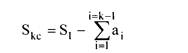 est la somme des quantités dont ladite extrémité libre de l'élément allongé de référence s'est déplacée pendant les mises en tension des torons d'ordre 1 à k-1.
- Selon une variante, ladite valeur de consigne Skc est calculée d'après la
formule :

- On peut utiliser l'un des torons du câble à tendre à titre d'élément allongé de référence. Dans ce cas, ledit toron servant d'élément allongé de référence est tendu et ancré en dernier.
- Lesdits moyens de calcul et de commande comprennent :
- a). un moyen de calcul qui, préalablement à la mise en tension dudit toron
d'ordre k calcule une valeur de consigne Skc pour le déplacement de l'extrémité dudit
toron d'ordre k à tendre, ladite valeur de consigne étant calculée d'après la formule :
où S1 est la valeur du déplacement mémorisée dans le premier moyen de mémorisation à la fin de la mise en tension du toron d'ordre 1 qui a été tendu le premier, et
 est la somme des valeurs de déplacement de l'extrémité libre de l'élément allongé de référence pendant les mises en tension des torons d'ordre 1 à k-1 ;
- b). un comparateur ayant une première entrée reliée à la sortie du moyen de calcul et une seconde entrée reliée audit premier capteur de déplacement, pour comparer une valeur réelle instantanée de déplacement de l'extrémité du toron d'ordre k en cours de mise en tension à ladite valeur de consigne Skc, et pour fournir un signal de commande en cas d'égalité de ladite valeur réelle instantanée et de ladite valeur de consigne ; et
- c). un moyen de commande qui est relié à la sortie du comparateur et qui réagit au signal de commande de celui-ci pour commander l'arrêt de l'appareil de traction.
- Le dispositif comprend en outre un moyen d'entrée pour introduire dans
ledit moyen de calcul une valeur de compensation e correspondant à la rétraction
d'un toron lors de l'ancrage de son extrémité soumise à la traction, et en ce que ledit
moyen de calcul calcule ladite valeur de consigne Skc d'après la formule :
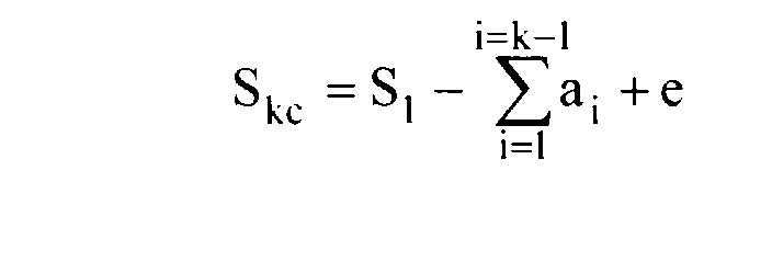
- L'élément allongé de référence peut être constitué par l'un des torons du câble à tendre.
- les figures 1 et 2 sont des schémas illustrant le principe général du procédé selon l'invention, la figure 1 correspondant à un état initial avant mise en tension d'un toron quelconque du câble, d'ordre k ≥ 2 dans la succession des opérations de tension des torons du câble, la figure 2 correspondant à un état final après mise en tension dudit toron d'ordre k ;
- les figures 3a à 3f sont des schémas illustrant des étapes successives du procédé selon l'invention ;
- la figure 4 est un schéma fonctionnel montrant un mode de réalisation du dispositif selon l'invention.
- t1, t2, t3.... tk-1, tk....tn-1, tn désignent les torons du câble dans l'ordre suivant lequel ils sont mis en tension, n étant le nombre total des torons du câble et k étant un nombre tel que 2 ≤ k ≤ n ;
- L0 désigne la longueur curviligne ( mesurée entre les deux ancrages A1 et A2) du toron de référence tref et du premier toron t1 avant mise en tension du toron t1 ;
- N01 désigne la tension initiale donnée au premier toron t1 au début du processus de mise en tension des torons du câble ;
- L1, L2, L3... désignent les longueurs curvilignes des torons (mesurées entre les ancrages A1 et A2) respectivement après la mise en tension du toron t1, t2, t3...., étant rappelé que, à tout moment, tous les torons déjà installés à ce moment dans la gaine 4 ont la même longueur curviligne ;
- L01, L02, L03.... désignent les longueurs à vide (à tension nulle) des torons t1, t2, t3...., considérés comme étant limités aux deux sections qui sont ancrées dans les têtes d'ancrage TA1 et TA2, après mise en tension desdits torons ;
- ΔLi,j désigne l'allongement du toron ti après mise en tension du toron tj ;
- S1, S2, S3....Sk-1, Sk....Sn désignent les valeurs du déplacement (mesurées par le capteur de déplacement 2) d'un point de référence de l'extrémité du toron t1, t2, t3....tk-1, tk....tn qui, à l'instant considéré, est tiré par le vérin de traction 1 ;
- a1 , a2, a3....ak-1, ak....an désignent les valeurs du déplacement (mesurées par
le capteur de déplacement 3) d'un point de référence de l'extrémité libre du toron de
référence tref, respectivement après mise en tension du toron t1, t2, t3....tk-1, tk....tn
(Dans les figures 1 et 2, on notera que




Claims (9)
- Procédé pour tendre un câble formé d'un faisceau de plusieurs torons maintenus parallèles les uns aux autres entre deux ancrages (A1 et A2) consistant à tendre individuellement et successivement les différents torons (tk) du câble à l'aide d'un appareil de traction (1), caractérisé en ce qu'il consiste :a). à installer un élément allongé de référence (tref) de telle sorte qu'il soit colinéaire au câble et qu'une de ses extrémités soit attachée à un point fixe (TA1), tandis que son autre extrémité est libre de se déplacer à travers l'un (A2) des deux ancrages (A1 et A2) du câble ;b). à tendre un premier toron (t1) en exerçant une traction sur une extrémité de celui-ci jusqu'à ce que sa tension ou son allongement atteigne une valeur prédéfinie, et à ancrer alors ladite extrémité dudit premier toron ;c). à mesurer une première quantité (S1) dont ladite extrémité du premier toron (t1), soumise à ladite traction, s'est déplacée pendant l'étape b) ;d). à mesurer une seconde quantité (a1) dont ladite extrémité libre de l'élément allongé de référence (tref) s'est déplacée pendant l'étape b) ;e). à tendre un second toron (t2) en exerçant une traction sur une extrémité de celui-ci jusqu'à ce que ladite extrémité du second toron se soit déplacée d'une quantité prédéfinie (S2) correspondant à la différence entre lesdites première et seconde quantités (S1 et a1) mesurées aux étapes c) et d), et à ancrer alors ladite extrémité dudit second toron (t2) ;f). à mesurer une quantité supplémentaire (a2) dont ladite extrémité libre de l'élément allongé de référence (tref) s'est déplacée pendant l'étape e) ;g). à tendre un troisième toron (t3) en exerçant une traction sur une extrémité de celui-ci jusqu'à ce que ladite extrémité du troisième toron se soit déplacée d'une quantité prédéfinie (S3) correspondant à la différence entre ladite quantité prédéfinie (S2) de déplacement de l'extrémité dudit second toron (t2) pendant l'étape e) et ladite quantité supplémentaire (a2) de déplacement de l'extrémité libre de l'élément allongé de référence (tref) pendant l'étape e), et à ancrer alors ladite extrémité dudit troisième toron (t3);h). à mesurer une quantité supplémentaire (a3) dont ladite extrémité libre de l'élément allongé de référence (tref) s'est déplacée pendant l'étape g) ;i). et ainsi de suite jusqu'à la mise en tension et l'ancrage du dernier toron (tn) sur lequel on exerce une traction jusqu'à ce que son extrémité soumise à la traction se soit déplacée d'une quantité prédéfinie correspondant à la différence entre la quantité prédéfinie de déplacement de l'extrémité, soumise à la traction, de l'avant dernier toron (tn-1) pendant sa mise en tension et la quantité supplémentaire de déplacement de l'extrémité libre de l'élément allongé de référence (tref) pendant la mise en tension de l'avant dernier toron (tn-1), et à ancrer alors ladite extrémité dudit dernier toron (tn).
- Procédé selon la revendication 1, caractérisé en ce que pour la mise en tension et l'ancrage d'un toron (tk) d'ordre k (2 ≤ k ≤ n, n étant le nombre de torons du câble) on calcule une valeur de consigne (Skc) pour le déplacement de l'extrémité du kième toron à tendre, on tire sur ladite extrémité tout en mesurant son déplacement réel (Skr), on compare, pendant ledit déplacement, la valeur réelle mesurée (Skr) du déplacement à ladite valeur de consigne (Skc) et, lorsque ladite valeur réelle mesurée atteint ladite valeur de consigne, on cesse de tirer sur le kième toron et simultanément on ancre son extrémité.
- Procédé selon la revendication 2, caractérisé en ce que la valeur de consigne (Skc) est calculée d'après la formule :où S1 est ladite première quantité de déplacement du premier toron et
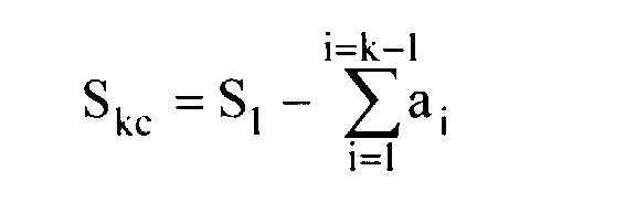 est la somme des quantités dont ladite extrémité libre de l'élément allongé de référence (tref) s'est déplacée pendant les mises en tension des torons d'ordre 1 à (k-1).
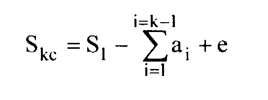
- Procédé selon la revendication 2, caractérisé en ce que ladite valeur de consigne (Skc) est calculée d'après la formule :où e est une valeur prédéfinie de compensation tenant compte d'une rétraction du kième toron au moment de l'ancrage de son extrémité soumise à la traction.
- Procédé selon l'une quelconque des revendications 1 à 4, caractérisé en ce qu'on utilise l'un des torons du câble à tendre à titre d'élément allongé de référence (tref), et en ce que ledit toron (tref) servant d'élément allongé de référence est tendu et ancré en dernier.
- Dispositif pour tendre un câble multi-torons entre deux ancrages (A1 et A2), comprenant un appareil de traction (1) pouvant être adapté successivement à chacun des torons (tk) du câble pour les tendre individuellement et successivement, caractérisé en ce qu'il comprend :a). un élément allongé de référence (tref) qui est associé au câble à tendre de telle façon qu'il soit colinéaire audit câble et qu'une de ses extrémités soit attachée en un point fixe (TA1), tandis que son autre extrémité est libre de se déplacer à travers un trou de l'un (A2) des deux ancrages (A1 et A2) du câble ;b). un premier capteur de déplacement (2) apte à être adapté successivement à chacun des torons du câble pour mesurer à chaque fois le déplacement d'une extrémité du toron (tk) auquel le premier capteur (2) est adapté lorsque ladite extrémité du toron est soumise à une traction par ledit appareil de traction (1) ;c). un premier moyen de mémorisation (13) relié au premier capteur de déplacement (2) pour mémoriser au moins la valeur (S1) du déplacement de l'extrémité du toron (t1) qui est tendu le premier ;d). un second capteur de déplacement (3) associé à l'élément allongé de référence (tref) pour mesurer le déplacement de son extrémité libre chaque fois qu'un toron (tk) du câble est mis en tension et ancré ;e). un second moyen de mémorisation (16) relié au second capteur de déplacement (3) pour mémoriser les valeurs de déplacement mesurées par ledit second capteur (3) ;f). des moyens de calcul (15) et de commande (14, 17) reliés audit premier capteur de déplacement (2) et auxdits premier et second moyens de mémorisation (13, 16) pour commander automatiquement l'arrêt de la traction exercée sur un toron (tk) d'ordre k (2 ≤ k ≤ n) du câble lorsque la valeur du déplacement (Skr) mesurée par le premier capteur de déplacement (2) atteint, pour ledit toron donné d'ordre k, une valeur de déplacement prédéfinie (Skc) correspondant à la différence entre la valeur prédéfinie de déplacement de l'extrémité du toron (tk-1) d'ordre (k-1) pendant la mise en tension de ce toron d'ordre (k-1) et la valeur de déplacement de l'extrémité libre de l'élément allongé de référence (tref) pendant la mise en tension dudit toron d'ordre (k-1).
- Dispositif selon la revendication 6, caractérisé en ce que lesdits moyens de calcul (15) et de commande (14, 17) comportent :a). un moyen de calcul (15) qui, préalablement à la mise en tension dudit toron (tk) d'ordre k, calcule une valeur de consigne (Skc) pour le déplacement de l'extrémité dudit toron (tk) d'ordre k à tendre, ladite valeur de consigne étant calculée d'après la formule :où S1 est la valeur du déplacement mémorisée dans le premier moyen de mémorisation (13) à la fin de la mise en tension du toron (t1) d'ordre 1 qui a été tendu le premier, et
 est la somme des valeurs de déplacement de l'extrémité libre de l'élément allongé de référence (tref) pendant les mises en tension des torons d'ordre 1 à (k-1).
 b). un comparateur (14) ayant une première entrée (+) reliée à la sortie du moyen de calcul (15) et une seconde entrée (-) reliée audit premier capteur de déplacement (2), pour comparer une valeur réelle instantanée (Skr) de déplacement de l'extrémité du toron (tk) d'ordre k en cours de mise en tension à ladite valeur de consigne (Skc), et pour fournir un signal de commande en cas d'égalité de ladite valeur réelle instantanée et de ladite valeur de consigne ; etc). un moyen de commande (17) qui est relié à la sortie du comparateur (14) et qui réagit au signal de commande de celui-ci pour commander l'arrêt de l'appareil de traction (1).
 - Dispositif selon la revendication 7, caractérisé en ce qu'il comprend en outre un moyen d'entrée pour introduire dans ledit moyen de calcul (15) une valeur de compensation (e) correspondant à la rétraction d'un toron (tk) lors de l'ancrage de son extrémité soumise à la traction, et en ce que ledit moyen de calcul (15) calcule ladite valeur de consigne (Skc) d'après la formule :

- Dispositif selon l'une quelconque des revendications 6 à 8, caractérisé en ce que l'élément allongé de référence (tref) est l'un des torons du câble à tendre.
Applications Claiming Priority (2)
| Application Number | Priority Date | Filing Date | Title |
|---|---|---|---|
| FR9907477 | 1999-06-14 | ||
| FR9907477A FR2794783B1 (fr) | 1999-06-14 | 1999-06-14 | Procede et dispositif pour tendre un cable multi-torons entre deux ancrages |
Publications (2)
| Publication Number | Publication Date |
|---|---|
| EP1061204A1 true EP1061204A1 (fr) | 2000-12-20 |
| EP1061204B1 EP1061204B1 (fr) | 2005-07-06 |
Family
ID=9546731
Family Applications (1)
| Application Number | Title | Priority Date | Filing Date |
|---|---|---|---|
| EP00401635A Expired - Lifetime EP1061204B1 (fr) | 1999-06-14 | 2000-06-09 | Procédé et dispositif pour tendre un câble multi-torons entre deux ancrages |
Country Status (8)
| Country | Link |
|---|---|
| EP (1) | EP1061204B1 (fr) |
| JP (1) | JP4427168B2 (fr) |
| KR (1) | KR100607116B1 (fr) |
| AT (1) | ATE299216T1 (fr) |
| DE (1) | DE60021147D1 (fr) |
| ES (1) | ES2245296T3 (fr) |
| FR (1) | FR2794783B1 (fr) |
| PT (1) | PT1061204E (fr) |
Cited By (6)
| Publication number | Priority date | Publication date | Assignee | Title |
|---|---|---|---|---|
| WO2002020904A1 (fr) * | 2000-09-08 | 2002-03-14 | Michel Marchetti | Procede de mise en tension de haubans a torons multiples |
| WO2006097632A1 (fr) * | 2005-03-17 | 2006-09-21 | Freyssinet | Procede de detection de rupture au sein d'une structure et systeme pour la mise en œuvre du procede |
| WO2007139702A3 (fr) * | 2006-05-25 | 2008-01-17 | Actuant Corp | Système et procédé de mise en tension automatique d'armatures de précontrainte monotoron |
| WO2010006706A1 (fr) * | 2008-07-14 | 2010-01-21 | Dywidag-Systems International Gmbh | Dispositif et procédé pour commander un vérin de mise sous tension lors de la mise sous tension d'un organe de tension |
| ITPC20090001A1 (it) * | 2009-01-08 | 2010-07-09 | Stefano Zambelli | Dispositivo modulare per la programmazione, controllo e registrazione dei valori di tesatura di trecce e trefoli pretesi e postesi negli stabilimenti e cantieri fissi e mobili di prefabbricazione di manufatti in calcestruzzo |
| EP3388580A1 (fr) * | 2017-04-11 | 2018-10-17 | Dywidag-Systems International GmbH | Dispositif de prévention de dégivrage et de givrage pour la chemise tubulaire d'un organe de serrage, organe de serrage pourvu d'un tel dispositif et construction pourvu d'au moins un tel organe de serrage |
Families Citing this family (4)
| Publication number | Priority date | Publication date | Assignee | Title |
|---|---|---|---|---|
| JP5365834B2 (ja) * | 2008-09-18 | 2013-12-11 | 清水建設株式会社 | ケーブルへの張力導入方法 |
| KR101299963B1 (ko) * | 2011-11-11 | 2013-08-26 | 대림산업 주식회사 | 콤팩트 멀티-스트랜드 케이블의 가설방법 |
| KR101753702B1 (ko) | 2015-06-05 | 2017-07-19 | 주식회사 포스코건설 | 교량의 ms 케이블 균등긴장 제어 방법 및 장치 |
| KR20200119514A (ko) * | 2019-04-10 | 2020-10-20 | 에프이엔 주식회사 | 케이블 자동 인장 시스템 및 자동 인장 방법 |
Citations (4)
| Publication number | Priority date | Publication date | Assignee | Title |
|---|---|---|---|---|
| FR703079A (fr) * | 1929-10-23 | 1931-04-23 | Felten & Guilleaume Carlswerk | Câble métallique avec dispositif pour en mesurer l'allongement |
| JPH02240374A (ja) * | 1989-03-10 | 1990-09-25 | Joban Kosan Kk | Pc綱線の同時緊張管理装置 |
| FR2652866A1 (fr) * | 1989-10-05 | 1991-04-12 | Freyssinet Int Stup | Perfectionnements aux procedes et dispositifs pour mettre sous tension des cables a brins multiples. |
| US5809710A (en) * | 1995-09-30 | 1998-09-22 | Dyckerhoff & Widmann Aktiengesellschaft | Method of tensioning a tension member composed of a plurality of individual elements |
-
1999
- 1999-06-14 FR FR9907477A patent/FR2794783B1/fr not_active Expired - Fee Related
-
2000
- 2000-06-09 PT PT00401635T patent/PT1061204E/pt unknown
- 2000-06-09 ES ES00401635T patent/ES2245296T3/es not_active Expired - Lifetime
- 2000-06-09 AT AT00401635T patent/ATE299216T1/de not_active IP Right Cessation
- 2000-06-09 EP EP00401635A patent/EP1061204B1/fr not_active Expired - Lifetime
- 2000-06-09 DE DE60021147T patent/DE60021147D1/de not_active Expired - Lifetime
- 2000-06-13 KR KR1020000032459A patent/KR100607116B1/ko not_active Expired - Fee Related
- 2000-06-13 JP JP2000176861A patent/JP4427168B2/ja not_active Expired - Fee Related
Patent Citations (4)
| Publication number | Priority date | Publication date | Assignee | Title |
|---|---|---|---|---|
| FR703079A (fr) * | 1929-10-23 | 1931-04-23 | Felten & Guilleaume Carlswerk | Câble métallique avec dispositif pour en mesurer l'allongement |
| JPH02240374A (ja) * | 1989-03-10 | 1990-09-25 | Joban Kosan Kk | Pc綱線の同時緊張管理装置 |
| FR2652866A1 (fr) * | 1989-10-05 | 1991-04-12 | Freyssinet Int Stup | Perfectionnements aux procedes et dispositifs pour mettre sous tension des cables a brins multiples. |
| US5809710A (en) * | 1995-09-30 | 1998-09-22 | Dyckerhoff & Widmann Aktiengesellschaft | Method of tensioning a tension member composed of a plurality of individual elements |
Non-Patent Citations (1)
| Title |
|---|
| PATENT ABSTRACTS OF JAPAN vol. 014, no. 563 (M - 1058) 14 December 1990 (1990-12-14) * |
Cited By (13)
| Publication number | Priority date | Publication date | Assignee | Title |
|---|---|---|---|---|
| WO2002020904A1 (fr) * | 2000-09-08 | 2002-03-14 | Michel Marchetti | Procede de mise en tension de haubans a torons multiples |
| FR2813907A1 (fr) * | 2000-09-08 | 2002-03-15 | Michel Marchetti | Procede de mise en tension de haubans a torons multiples |
| GB2439031B (en) * | 2005-03-17 | 2010-01-20 | Freyssinet | Method for detecting a rupture within a structure and system for implementing said method |
| FR2883376A1 (fr) * | 2005-03-17 | 2006-09-22 | Fressinet Internat Stup | Procede de detection de rupture au sein d'une structure et systeme pour la mise en oeuvre du procede |
| GB2439031A (en) * | 2005-03-17 | 2007-12-12 | Freyssinet | Method for dectecting a rupture inside a structure and system for implementing said method |
| WO2006097632A1 (fr) * | 2005-03-17 | 2006-09-21 | Freyssinet | Procede de detection de rupture au sein d'une structure et systeme pour la mise en œuvre du procede |
| US8001852B2 (en) | 2005-03-17 | 2011-08-23 | Freyssinet | Method for detecting a rupture inside a structure and system for implementing said method |
| WO2007139702A3 (fr) * | 2006-05-25 | 2008-01-17 | Actuant Corp | Système et procédé de mise en tension automatique d'armatures de précontrainte monotoron |
| WO2010006706A1 (fr) * | 2008-07-14 | 2010-01-21 | Dywidag-Systems International Gmbh | Dispositif et procédé pour commander un vérin de mise sous tension lors de la mise sous tension d'un organe de tension |
| US8702066B2 (en) | 2008-07-14 | 2014-04-22 | Dywidag-Systems International Gmbh | Device and method for controlling a prestressing jack when tensioning a tendon |
| ITPC20090001A1 (it) * | 2009-01-08 | 2010-07-09 | Stefano Zambelli | Dispositivo modulare per la programmazione, controllo e registrazione dei valori di tesatura di trecce e trefoli pretesi e postesi negli stabilimenti e cantieri fissi e mobili di prefabbricazione di manufatti in calcestruzzo |
| EP3388580A1 (fr) * | 2017-04-11 | 2018-10-17 | Dywidag-Systems International GmbH | Dispositif de prévention de dégivrage et de givrage pour la chemise tubulaire d'un organe de serrage, organe de serrage pourvu d'un tel dispositif et construction pourvu d'au moins un tel organe de serrage |
| US10663035B2 (en) | 2017-04-11 | 2020-05-26 | Dywidag-Systems International Gmbh | Apparatus for de-icing the casing tube of a tendon |
Also Published As
| Publication number | Publication date |
|---|---|
| EP1061204B1 (fr) | 2005-07-06 |
| JP2001032213A (ja) | 2001-02-06 |
| ES2245296T3 (es) | 2006-01-01 |
| PT1061204E (pt) | 2005-11-30 |
| ATE299216T1 (de) | 2005-07-15 |
| KR100607116B1 (ko) | 2006-08-01 |
| JP4427168B2 (ja) | 2010-03-03 |
| DE60021147D1 (de) | 2005-08-11 |
| KR20010020985A (ko) | 2001-03-15 |
| FR2794783B1 (fr) | 2001-08-03 |
| FR2794783A1 (fr) | 2000-12-15 |
Similar Documents
| Publication | Publication Date | Title |
|---|---|---|
| EP1061204B1 (fr) | Procédé et dispositif pour tendre un câble multi-torons entre deux ancrages | |
| EP0421862B1 (fr) | Perfectionnements aux procédés et dispositifs pour mettre sous tension des câbles à brins multiples | |
| FR2813907A1 (fr) | Procede de mise en tension de haubans a torons multiples | |
| EP1751513B1 (fr) | Procede de controle de la mise sous tension d'une tige de boulon, du type vis ou goujon d'assemblage, et dispositif de mise en oeuvre d'un tel procede | |
| FR2820506A1 (fr) | Procede de mesure d'une capacite de condensateur | |
| FR2918173A1 (fr) | Mise en charge d'une machine d'essai de fluage | |
| WO2014095640A1 (fr) | Procede et dispositif de caracterisation d'un module de stockage d'energie par effet capacitif | |
| EP1020240B1 (fr) | Procédé de régulation des tractions/compressions dans un laminoir multicage à chaud et système de commande correspondant | |
| CA2326648C (fr) | Procede pour mesurer par ultrasons la tension residuelle d'une barre de precontrainte | |
| WO2014128027A1 (fr) | Capteur a accelerometre pendulaire electrostatique et procede de commande d'un tel capteur | |
| EP0357670B1 (fr) | Jigger | |
| EP1120176A1 (fr) | Procédé de réglage de la course d'une presse-plieuse | |
| EP3503380B1 (fr) | Procédé de commande d'un moteur électrique incluant une séquence d'identification d'un transformateur | |
| FR3087162A1 (fr) | Systeme de diagnostic sur place de la batterie d'un velo electrique | |
| EP3816091A1 (fr) | Grue à tour avec poinçon à pliage et dépliage automatiques | |
| Yoshida et al. | Dynamic features of plectoneme formation of twisted DNA at low force | |
| EP4380042B1 (fr) | Procédé et système de réglage et de mesure pour centrale photovoltaïque | |
| FR2570826A1 (fr) | Dispositif de mesure de la resistance a l'arrachement d'un materiau ou d'un composant mecanique de construction | |
| WO2013190236A2 (fr) | Dispositif d'alimentation d'un circuit électronique | |
| FR2650894A1 (fr) | Procede de mesure rapide des caracteristiques mecaniques de fils, constitues d'elements continus et/ou discontinus et dispositif pour la mise en oeuvre de ce procede | |
| FR2855851A1 (fr) | Procede et appareil de commande de plusieurs injecteurs d'un moteur a combustion interne | |
| EP0619475B1 (fr) | Dispositif de mesure de niveau et/ou de volume de liquide à fil résistif immergé | |
| FR2777348A1 (fr) | Procede de mesure d'un niveau d'huile, et dispositif pour la mise en oeuvre de ce procede | |
| EP0707216A2 (fr) | Procédé et pince ampèremétrique pour la détermination de la capacité de compensation destinée à un réseau électrique | |
| EP1094594A1 (fr) | Variateur pour la commande d'un moteur électrique de levage |
Legal Events
| Date | Code | Title | Description |
|---|---|---|---|
| PUAI | Public reference made under article 153(3) epc to a published international application that has entered the european phase |
Free format text: ORIGINAL CODE: 0009012 |
|
| AK | Designated contracting states |
Kind code of ref document: A1 Designated state(s): AT BE CH CY DE DK ES FI FR GB GR IE IT LI LU MC NL PT SE |
|
| AX | Request for extension of the european patent |
Free format text: AL;LT;LV;MK;RO;SI |
|
| 17P | Request for examination filed |
Effective date: 20010209 |
|
| AKX | Designation fees paid |
Free format text: AT BE CH CY DE DK ES FI FR GB GR IE IT LI LU MC NL PT SE |
|
| RAP1 | Party data changed (applicant data changed or rights of an application transferred) |
Owner name: VINCI CONSTRUCTION GRANDS PROJETS Owner name: GTM CONSTRUCTION S.A. |
|
| 17Q | First examination report despatched |
Effective date: 20031117 |
|
| GRAP | Despatch of communication of intention to grant a patent |
Free format text: ORIGINAL CODE: EPIDOSNIGR1 |
|
| GRAS | Grant fee paid |
Free format text: ORIGINAL CODE: EPIDOSNIGR3 |
|
| GRAA | (expected) grant |
Free format text: ORIGINAL CODE: 0009210 |
|
| AK | Designated contracting states |
Kind code of ref document: B1 Designated state(s): AT BE CH CY DE DK ES FI FR GB GR IE IT LI LU MC NL PT SE |
|
| PG25 | Lapsed in a contracting state [announced via postgrant information from national office to epo] |
Ref country code: IT Free format text: LAPSE BECAUSE OF FAILURE TO SUBMIT A TRANSLATION OF THE DESCRIPTION OR TO PAY THE FEE WITHIN THE PRESCRIBED TIME-LIMIT;WARNING: LAPSES OF ITALIAN PATENTS WITH EFFECTIVE DATE BEFORE 2007 MAY HAVE OCCURRED AT ANY TIME BEFORE 2007. THE CORRECT EFFECTIVE DATE MAY BE DIFFERENT FROM THE ONE RECORDED. Effective date: 20050706 Ref country code: IE Free format text: LAPSE BECAUSE OF FAILURE TO SUBMIT A TRANSLATION OF THE DESCRIPTION OR TO PAY THE FEE WITHIN THE PRESCRIBED TIME-LIMIT Effective date: 20050706 Ref country code: FI Free format text: LAPSE BECAUSE OF FAILURE TO SUBMIT A TRANSLATION OF THE DESCRIPTION OR TO PAY THE FEE WITHIN THE PRESCRIBED TIME-LIMIT Effective date: 20050706 Ref country code: AT Free format text: LAPSE BECAUSE OF FAILURE TO SUBMIT A TRANSLATION OF THE DESCRIPTION OR TO PAY THE FEE WITHIN THE PRESCRIBED TIME-LIMIT Effective date: 20050706 |
|
| REG | Reference to a national code |
Ref country code: GB Ref legal event code: FG4D Free format text: NOT ENGLISH |
|
| REG | Reference to a national code |
Ref country code: CH Ref legal event code: EP |
|
| REG | Reference to a national code |
Ref country code: IE Ref legal event code: FG4D Free format text: LANGUAGE OF EP DOCUMENT: FRENCH |
|
| REF | Corresponds to: |
Ref document number: 60021147 Country of ref document: DE Date of ref document: 20050811 Kind code of ref document: P |
|
| PG25 | Lapsed in a contracting state [announced via postgrant information from national office to epo] |
Ref country code: SE Free format text: LAPSE BECAUSE OF FAILURE TO SUBMIT A TRANSLATION OF THE DESCRIPTION OR TO PAY THE FEE WITHIN THE PRESCRIBED TIME-LIMIT Effective date: 20051006 Ref country code: DK Free format text: LAPSE BECAUSE OF FAILURE TO SUBMIT A TRANSLATION OF THE DESCRIPTION OR TO PAY THE FEE WITHIN THE PRESCRIBED TIME-LIMIT Effective date: 20051006 |
|
| PG25 | Lapsed in a contracting state [announced via postgrant information from national office to epo] |
Ref country code: DE Free format text: LAPSE BECAUSE OF FAILURE TO SUBMIT A TRANSLATION OF THE DESCRIPTION OR TO PAY THE FEE WITHIN THE PRESCRIBED TIME-LIMIT Effective date: 20051007 |
|
| GBT | Gb: translation of ep patent filed (gb section 77(6)(a)/1977) |
Effective date: 20051003 |
|
| REG | Reference to a national code |
Ref country code: GR Ref legal event code: EP Ref document number: 20050402885 Country of ref document: GR |
|
| REG | Reference to a national code |
Ref country code: ES Ref legal event code: FG2A Ref document number: 2245296 Country of ref document: ES Kind code of ref document: T3 |
|
| REG | Reference to a national code |
Ref country code: IE Ref legal event code: FD4D |
|
| PLBE | No opposition filed within time limit |
Free format text: ORIGINAL CODE: 0009261 |
|
| STAA | Information on the status of an ep patent application or granted ep patent |
Free format text: STATUS: NO OPPOSITION FILED WITHIN TIME LIMIT |
|
| 26N | No opposition filed |
Effective date: 20060407 |
|
| PG25 | Lapsed in a contracting state [announced via postgrant information from national office to epo] |
Ref country code: CH Free format text: LAPSE BECAUSE OF NON-PAYMENT OF DUE FEES Effective date: 20060630 Ref country code: LI Free format text: LAPSE BECAUSE OF NON-PAYMENT OF DUE FEES Effective date: 20060630 Ref country code: MC Free format text: LAPSE BECAUSE OF NON-PAYMENT OF DUE FEES Effective date: 20060630 |
|
| REG | Reference to a national code |
Ref country code: CH Ref legal event code: PL |
|
| PG25 | Lapsed in a contracting state [announced via postgrant information from national office to epo] |
Ref country code: CY Free format text: LAPSE BECAUSE OF FAILURE TO SUBMIT A TRANSLATION OF THE DESCRIPTION OR TO PAY THE FEE WITHIN THE PRESCRIBED TIME-LIMIT Effective date: 20050706 |
|
| REG | Reference to a national code |
Ref country code: FR Ref legal event code: TQ |
|
| REG | Reference to a national code |
Ref country code: FR Ref legal event code: PLFP Year of fee payment: 17 |
|
| REG | Reference to a national code |
Ref country code: FR Ref legal event code: PLFP Year of fee payment: 18 |
|
| REG | Reference to a national code |
Ref country code: FR Ref legal event code: PLFP Year of fee payment: 19 |
|
| PGFP | Annual fee paid to national office [announced via postgrant information from national office to epo] |
Ref country code: NL Payment date: 20190527 Year of fee payment: 20 Ref country code: LU Payment date: 20190524 Year of fee payment: 20 |
|
| PGFP | Annual fee paid to national office [announced via postgrant information from national office to epo] |
Ref country code: PT Payment date: 20190603 Year of fee payment: 20 |
|
| PGFP | Annual fee paid to national office [announced via postgrant information from national office to epo] |
Ref country code: FR Payment date: 20190522 Year of fee payment: 20 Ref country code: GR Payment date: 20190523 Year of fee payment: 20 Ref country code: BE Payment date: 20190523 Year of fee payment: 20 |
|
| PGFP | Annual fee paid to national office [announced via postgrant information from national office to epo] |
Ref country code: ES Payment date: 20190701 Year of fee payment: 20 Ref country code: GB Payment date: 20190522 Year of fee payment: 20 |
|
| REG | Reference to a national code |
Ref country code: NL Ref legal event code: MK Effective date: 20200608 |
|
| REG | Reference to a national code |
Ref country code: GB Ref legal event code: PE20 Expiry date: 20200608 |
|
| PG25 | Lapsed in a contracting state [announced via postgrant information from national office to epo] |
Ref country code: PT Free format text: LAPSE BECAUSE OF EXPIRATION OF PROTECTION Effective date: 20200622 |
|
| REG | Reference to a national code |
Ref country code: BE Ref legal event code: MK Effective date: 20200609 |
|
| PG25 | Lapsed in a contracting state [announced via postgrant information from national office to epo] |
Ref country code: GB Free format text: LAPSE BECAUSE OF EXPIRATION OF PROTECTION Effective date: 20200608 |
|
| REG | Reference to a national code |
Ref country code: ES Ref legal event code: FD2A Effective date: 20200925 |
|
| PG25 | Lapsed in a contracting state [announced via postgrant information from national office to epo] |
Ref country code: ES Free format text: LAPSE BECAUSE OF EXPIRATION OF PROTECTION Effective date: 20200610 |