EP1061191A2 - Klammer für die Montage an einem Gurt - Google Patents
Klammer für die Montage an einem Gurt Download PDFInfo
- Publication number
- EP1061191A2 EP1061191A2 EP00304960A EP00304960A EP1061191A2 EP 1061191 A2 EP1061191 A2 EP 1061191A2 EP 00304960 A EP00304960 A EP 00304960A EP 00304960 A EP00304960 A EP 00304960A EP 1061191 A2 EP1061191 A2 EP 1061191A2
- Authority
- EP
- European Patent Office
- Prior art keywords
- flange
- limb
- clip
- bend
- edge
- Prior art date
- Legal status (The legal status is an assumption and is not a legal conclusion. Google has not performed a legal analysis and makes no representation as to the accuracy of the status listed.)
- Withdrawn
Links
- 230000001154 acute effect Effects 0.000 description 3
- 238000009413 insulation Methods 0.000 description 3
- 239000012774 insulation material Substances 0.000 description 2
- 239000000463 material Substances 0.000 description 2
- 150000001875 compounds Chemical class 0.000 description 1
- 238000010276 construction Methods 0.000 description 1
- 238000009434 installation Methods 0.000 description 1
Images


Classifications
-
- F—MECHANICAL ENGINEERING; LIGHTING; HEATING; WEAPONS; BLASTING
- F16—ENGINEERING ELEMENTS AND UNITS; GENERAL MEASURES FOR PRODUCING AND MAINTAINING EFFECTIVE FUNCTIONING OF MACHINES OR INSTALLATIONS; THERMAL INSULATION IN GENERAL
- F16B—DEVICES FOR FASTENING OR SECURING CONSTRUCTIONAL ELEMENTS OR MACHINE PARTS TOGETHER, e.g. NAILS, BOLTS, CIRCLIPS, CLAMPS, CLIPS OR WEDGES; JOINTS OR JOINTING
- F16B2/00—Friction-grip releasable fastenings
- F16B2/20—Clips, i.e. with gripping action effected solely by the inherent resistance to deformation of the material of the fastening
- F16B2/22—Clips, i.e. with gripping action effected solely by the inherent resistance to deformation of the material of the fastening of resilient material, e.g. rubbery material
- F16B2/24—Clips, i.e. with gripping action effected solely by the inherent resistance to deformation of the material of the fastening of resilient material, e.g. rubbery material of metal
- F16B2/248—Clips, i.e. with gripping action effected solely by the inherent resistance to deformation of the material of the fastening of resilient material, e.g. rubbery material of metal of wire
-
- E—FIXED CONSTRUCTIONS
- E04—BUILDING
- E04B—GENERAL BUILDING CONSTRUCTIONS; WALLS, e.g. PARTITIONS; ROOFS; FLOORS; CEILINGS; INSULATION OR OTHER PROTECTION OF BUILDINGS
- E04B1/00—Constructions in general; Structures which are not restricted either to walls, e.g. partitions, or floors or ceilings or roofs
- E04B1/62—Insulation or other protection; Elements or use of specified material therefor
- E04B1/92—Protection against other undesired influences or dangers
- E04B1/94—Protection against other undesired influences or dangers against fire
- E04B1/941—Building elements specially adapted therefor
- E04B1/943—Building elements specially adapted therefor elongated
- E04B1/944—Building elements specially adapted therefor elongated covered with fire-proofing material
-
- F—MECHANICAL ENGINEERING; LIGHTING; HEATING; WEAPONS; BLASTING
- F16—ENGINEERING ELEMENTS AND UNITS; GENERAL MEASURES FOR PRODUCING AND MAINTAINING EFFECTIVE FUNCTIONING OF MACHINES OR INSTALLATIONS; THERMAL INSULATION IN GENERAL
- F16B—DEVICES FOR FASTENING OR SECURING CONSTRUCTIONAL ELEMENTS OR MACHINE PARTS TOGETHER, e.g. NAILS, BOLTS, CIRCLIPS, CLAMPS, CLIPS OR WEDGES; JOINTS OR JOINTING
- F16B5/00—Joining sheets or plates, e.g. panels, to one another or to strips or bars parallel to them
- F16B5/06—Joining sheets or plates, e.g. panels, to one another or to strips or bars parallel to them by means of clamps or clips
- F16B5/0607—Joining sheets or plates, e.g. panels, to one another or to strips or bars parallel to them by means of clamps or clips joining sheets or plates to each other
- F16B5/0621—Joining sheets or plates, e.g. panels, to one another or to strips or bars parallel to them by means of clamps or clips joining sheets or plates to each other in parallel relationship
- F16B5/0635—Joining sheets or plates, e.g. panels, to one another or to strips or bars parallel to them by means of clamps or clips joining sheets or plates to each other in parallel relationship fastened over the edges of the sheets or plates
Definitions
- the present invention relates to a clip for mounting on a flange and in particular to a clip for attaching sheet material to steelwork, especially insulation for fire protection purposes, but without limitation to same.
- the steelwork has flanges and different thickness of flanges are employed according to the structural requirements of the steelwork.
- the flanges may range from 10 mm to 35 mm in thickness and it would be desirable if one clip could be used for such a range of flange thicknesses.
- US Patent No. 4043092 describes a prior art clip for attaching insulation to steelwork.
- the clip comprises a length of wire which is bent to form two free ends intended to be disposed substantially perpendicular to one another so that either or both may have the insulation material impaled thereon.
- the wire is bent around on itself in the manner of a spiral but with a series of straight sections each connected by a substantially 90° bend. This provides two straight sections which, in use, abut one side of the flange and two other straight sections which abut the other side of the flange and conveniently referred to as first and second elements respectively.
- a straight section of wire traverses the edge of the flange and connects the first and second elements.
- the length of the connecting element determines the maximum thickness of flange to which the clip can be fitted but nevertheless it has been found that thus design of clip is such that it is not readily suited to a wide range of flange thicknesses making it necessary to make a number of different sizes of clip, each of which is capable of being fitted to a limited range of flange thicknesses.
- the prior art clip presents stability problems, it cannot be used with dovetail decking and it is awkward to fit on thick flanges because the profile follows around and the top and bottom portions overlie one another.
- the clip provides a first abutment means which in use co-operates with one side of the flange and two second abutment means which in use, co-operate with the other side of flange.
- the first abutment means is intermediate the two second abutment means and thus requires two interconnecting limbs to traverse the edge of the flange.
- the clip provides two free ends associated with the respective second abutment means.
- the present invention aims to provide a clip which can be used for a wide range of flange thicknesses and yet which does not require two connecting limb portions traversing the edge of the flange.
- the present invention provides a clip for mounting on a flange and comprising a length of wire which is bent to form first and second elements which, in use, are disposed to one side and the other side of said flange, and a connecting limb portion traversing, in use, across the edge of the flange and connecting said first and second elements, first and second free ends associated respectively with the first and second elements, said first element comprising a first limb connecting with the connecting limb portion by a first bend and extending away therefrom over the flange and having a forward return bend to a second limb which extends back towards the edge of the flange at a position spaced from said first bend, said second limb leading to said first free end, said second element connecting with the other end of the connecting limb by way of a second bend and extending across said other side of the flange to said second free end, said second element having interconnected spaced positions which, in use, engage with said other side of the flange at spaced positions straddiing the position of engagement of the first and
- the spaced positions may constitute occasional contact points with the flange. Preferably there are at least two points of contact with the flange at positions straddling the position of contact of the first element. However, there may be intermediate contact positions and/or lines of contact and it is preferable that as much as possible of the second element lie in close proximity with the flange, up to equal contact through out the second element.
- the second element at least between said spaced positions is preferably disposed in a plane which lies substantially parallel with the plane of the flange.
- the second free end is connected to said second element by a bend (referred to as a second element end bend) so that the second free end is disposed substantially perpendicular to a plane in which said second element is disposed.
- Said second element (between said second bend and said second element end bend) may comprise a single limb which is curved there between or at least between said spaced positions or two or more straight limbs connected by respective bends.
- the second element may extend to a position adjacent the edge of the flange at which said second element end bend is disposed.
- Said second bend is preferably an acute bend and this has been found to be advantageous as it encourages the second element to lie flat against the flange.
- the clip is more easily fitted onto the flange. This is especially the case the thicker the flange.
- the first and second limbs of the first element preferably comprise a loop.
- said elements are disposed in a common plane which plane is, in use, substantially parallel to the plane of the flange.
- the forward return bend is such that when applied to a flange one or both of the said first and second limbs is displaced from a plane of said flange.
- Said first bend may be an acute bend which operates in conjunction with the compound bend of the forward return bend to dispose said second limb in the plane of the flange.
- the first element is constructed as a loop to enable the clip to be used where dovetail decking is fitted to the steelwork.
- the narrow width of the loop easily fits in the dovetail sections.
- Good stability is achieved by having the end of the second element at which the projecting end is located disposed adjacent to the edge of the flange. However, this is not essential. Good stability can be achieved with said end spaced from the edge of the flange although in such a situation stability is aided by arranging for the length of the first element to exceed the length of second element. In this context length means the distance that the first and second elements project onto the flange.
- said second limb may be provided with a bend positioned substantially in alignment with said first bend to provide a drop limb extending substantially in the same plane as the connecting limb, in use, so as to lie across the edge of the flange.
- said drop limb has a bend spaced from said drop bend which serves to position said first free end to extend from the edge of the flange to be disposed substantially perpendicular to said second free end.
- said second element comprises an are extending from the other end of the connecting limb past the position of the first element to a return bend disposed, in use, adjacent to the edge of the flange and which leads to a third limb extending onto the flange to position said second element end bend (which leads to said second free end) at a position on the flange inset from the edge thereof.
- the clips may be constructed as left or right handed.
- a first embodiment of clip which comprises a length of wire which is bent to form first and second projecting end portions 1, 3, and connecting limb means 5 which connects a first element with a second element.
- the first element comprises first and second limbs 7, 9.
- the first limb connects with the connecting limb portion 5 by way of a first bend 11 which turns through approximately 90°.
- the first and second limbs 7, 9 are connected by a forward going return bend 13 which turns through approximately 180°. This results in the second limb lying substantially parallel to the first limb and extending in the opposite direction.
- the first and second limbs are substantially the same length.
- the second limb 9 connects with the first projecting end 1 by way of a drop limb 15 and respective right angled bends 17, 19.
- the limbs 5 and 15 lie in substantially the same plane and the first projecting end 1 is disposed substantially perpendicular to said plane.
- the second element comprises two limbs conveniently referred to as third and fourth limbs 21, 22. They are connected by a substantially right-angled bend 23 although other angles could be used.
- the limb 21 connects with the connecting limb 5 by way of a second bend 25.
- the included angle of the second bend is acute as seen more clearly in Figure 2.
- the limbs 21 and 22 lie in a common plane.
- Limb 22 connects with the second projecting end 3 by way of a substantially right-angled bend 27. It will be noted that the second limb extends onto the flange by a greater amount than the first element.
- the limb 7 is inclined with respect to the plane occupied by limbs 21 and 22 in its as made condition - see Figure 2a, similarly it is preferred that limb 9 is inclined with respect to limb 7 again see Figure 2a in its as made condition.
- FIG 3 illustrates the configuration adopted when the clip is applied to a relatively narrow flange F.
- Limbs 21 and 22 of the second element lie substantially flat against the underside of a flange.
- the first element co-operates with the opposite side of the flange.
- the second element straddles the point of contact of the first element with the flange.
- the second limb 9 lies substantially flat against the flange whilst limb 7 is displaced due to the aforementioned angles of bends 11 and 13. Where these bends are not angled relative to the plane occupied by the limbs 21 and 22 then both limbs 7 and 9 may lie flat against the surface of the flange.
- the projecting free ends 1 and 3 lie substantially perpendicular to one another ready to receive insulation material.
- the design is such that the ends remain perpendicular when the clip is applied to different thiscknesses of flange. This is advantageous.
- FIG. 4-6 Another embodiment of the invention is now described with reference to Figures 4-6.
- This embodiment is substantially the same as that described with reference to Figures 1 to 3 and corresponding reference numerals have been used to denote identical parts and are not described in further detail.
- the difference resides in the configuration of the second element as well as the fact the hand is reversed.
- the second element has three limbs.
- the additional limb 24 is disposed between limbs 21' and 22' and connected thereto by bends 23a, 23b.
- the angle of these bends is substantially 90°.
- the second bend 25 turns to approximately 90°.
- the arrangement of the second element serves to provide spaced positions which engage with one side of the flange at a position straddling the position of engagement of the first element with the other side of the flange.
- These spaced positions may be at the bends 25, 27 or part way along the limbs 21,22 as is the case for the first embodiment.
- a third embodiment is described with reference to Figures 7-9.
- the construction is substantially the same as that of the embodiment of Figure 4 and serves to illustrate that the first element can have a greater projection on to the flange than the second element.
- limb 22' is omitted and the second projecting end 3 is formed at the end of limb 24 such that, in use, the projecting end is set in from the edge of the flange compared with the previously described embodiments where the projecting end 3 is positioned closely adjacent the edge of the flange.
- Good stability is achieved in this embodiment by increasing the length of the first element so that it extends onto the flange by a greater amount than the second element.
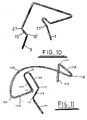
- Figure 10 illustrates a further embodiment and serves to demonstrate that the orientation of the respective first and second ends 1, 3 can be reversed.
- a clip of the type shown in Figure 1 is illustrated for convenience but it could be any of the other clips.
- the limb 1 which projects substantially perpendicular to the plane of the flange is now connected to the first element whilst the limb 3 which extends substantially perpendicular to the end 1 is now connected to the second element by way of a drop limb 15' and right angled bend 19' although not clearly apparent in the illustration.
- the drop limb and bends 27 and 19' may be omitted.
- Figure 11 illustrates yet another embodiment of clip. It comprises first and second projecting end portions 101, 103 and a connecting limb 105 which connects a first element with a second element.
- the first element is substantially the same as the first element of Figures 1, 2 or 4 and comprises first and second limbs 107, 109.
- the second limb connects with the end portion 101 by way of a drop limb 115 and bends 117, 119.
- the first limb 107 connects with the connecting limb 105 by way of bend 111 which is of the order of 90°.
- the second element differs from the previously described embodiment in that it comprises an arcuate element 124 which curves from bend 125 which connects it to the connecting limb 105 to a return bend 126.
- the return bend leads to a return limb 128 which has a bend 127 at the end thereof leading to the end portion 103.
- the second end portion 103 is inset from the edge of the flange.
- the return limb aids stability.
- the arcuate element extends over an are which straddles the location of the first element albeit to the opposite side of the flange.
- the arcuate element 124 and the return limb 128 preferably lie in a common plane. Preferably in use, they lie flat against the side of the flange.
- the first limb 107 of the first element lies flat against the flange, whilst the limb 109 is displaced from the flange.
- the second free end is disposed substantially perpendicular to a plane in which said arcuate element is disposed and/or the plane of the flange in which the clip is fitted.
- the first free end is disposed in a plane substantially parallel to the plane of the arcuate element and/or the plane of the flange to which the clip is fitted.
- the embodiment of the invention all illustrate the presence of a drop limb. However, this is not essential and may be omitted.
Landscapes
- Engineering & Computer Science (AREA)
- General Engineering & Computer Science (AREA)
- Mechanical Engineering (AREA)
- Architecture (AREA)
- Physics & Mathematics (AREA)
- Electromagnetism (AREA)
- Civil Engineering (AREA)
- Structural Engineering (AREA)
- Clamps And Clips (AREA)
Applications Claiming Priority (2)
| Application Number | Priority Date | Filing Date | Title |
|---|---|---|---|
| GB9913574 | 1999-06-14 | ||
| GBGB9913574.1A GB9913574D0 (en) | 1999-06-14 | 1999-06-14 | A clip for mounting on a flange |
Publications (2)
| Publication Number | Publication Date |
|---|---|
| EP1061191A2 true EP1061191A2 (de) | 2000-12-20 |
| EP1061191A3 EP1061191A3 (de) | 2002-01-02 |
Family
ID=10855140
Family Applications (1)
| Application Number | Title | Priority Date | Filing Date |
|---|---|---|---|
| EP00304960A Withdrawn EP1061191A3 (de) | 1999-06-14 | 2000-06-13 | Klammer für die Montage an einem Gurt |
Country Status (2)
| Country | Link |
|---|---|
| EP (1) | EP1061191A3 (de) |
| GB (2) | GB9913574D0 (de) |
Cited By (1)
| Publication number | Priority date | Publication date | Assignee | Title |
|---|---|---|---|---|
| US10156066B2 (en) | 2017-05-11 | 2018-12-18 | Calaco Solutions Ltd. | Corner bead clip for attaching to steel members |
Families Citing this family (1)
| Publication number | Priority date | Publication date | Assignee | Title |
|---|---|---|---|---|
| US12024877B2 (en) * | 2020-12-15 | 2024-07-02 | David John Simonsen | Insulation wire mounting system |
Citations (2)
| Publication number | Priority date | Publication date | Assignee | Title |
|---|---|---|---|---|
| US4043092A (en) | 1973-10-02 | 1977-08-23 | United States Gypsum Company | Clip for attaching insulation and the assembly thereof |
| EP0751263A1 (de) | 1995-06-30 | 1997-01-02 | H. GORDON & CO. LIMITED | Feuerschutz von Stahlträgern |
Family Cites Families (3)
| Publication number | Priority date | Publication date | Assignee | Title |
|---|---|---|---|---|
| US2921464A (en) * | 1955-03-10 | 1960-01-19 | Anders C Olsen | Building structure clip means |
| GB829504A (en) * | 1957-10-15 | 1960-03-02 | British Plaster Board Mfg Ltd | Improvements in or relating to securing sheeting to building structures |
| US3855895A (en) * | 1972-12-27 | 1974-12-24 | Western Electric Co | One-quarter turn fastener |
-
1999
- 1999-06-14 GB GBGB9913574.1A patent/GB9913574D0/en not_active Ceased
-
2000
- 2000-06-13 EP EP00304960A patent/EP1061191A3/de not_active Withdrawn
- 2000-06-13 GB GB0014248A patent/GB2351120B/en not_active Expired - Fee Related
Patent Citations (2)
| Publication number | Priority date | Publication date | Assignee | Title |
|---|---|---|---|---|
| US4043092A (en) | 1973-10-02 | 1977-08-23 | United States Gypsum Company | Clip for attaching insulation and the assembly thereof |
| EP0751263A1 (de) | 1995-06-30 | 1997-01-02 | H. GORDON & CO. LIMITED | Feuerschutz von Stahlträgern |
Cited By (1)
| Publication number | Priority date | Publication date | Assignee | Title |
|---|---|---|---|---|
| US10156066B2 (en) | 2017-05-11 | 2018-12-18 | Calaco Solutions Ltd. | Corner bead clip for attaching to steel members |
Also Published As
| Publication number | Publication date |
|---|---|
| GB0014248D0 (en) | 2000-08-02 |
| EP1061191A3 (de) | 2002-01-02 |
| GB2351120B (en) | 2003-04-16 |
| GB2351120A (en) | 2000-12-20 |
| GB9913574D0 (en) | 1999-08-11 |
Similar Documents
| Publication | Publication Date | Title |
|---|---|---|
| US6247871B1 (en) | Clip for joining wire-mesh structures | |
| US5111632A (en) | Expandable joist hanger | |
| US8585313B2 (en) | Post coupler | |
| US4924646A (en) | Wire guard | |
| CA2535216A1 (en) | Roof anchor | |
| JP4574685B2 (ja) | 取付け部材と基体とを結合するためのクランプ | |
| US20070012852A1 (en) | Grid-holding element | |
| WO2006086185A2 (en) | H clip | |
| JP2002255327A (ja) | コンベヤシステムに於ける走行フレーム装置 | |
| CA2559322C (en) | Post coupler | |
| JPS625817B2 (de) | ||
| EP1061191A2 (de) | Klammer für die Montage an einem Gurt | |
| GB2117821A (en) | Device for strapping cables pipes or other similar items together or to supports | |
| CA2586044C (en) | Cladding method and system for buildings | |
| US6916214B2 (en) | Connecting terminal | |
| TWI698592B (zh) | 可防塵的加強構造 | |
| JP2002039243A (ja) | ウエーブコイルばね | |
| EP1355076A3 (de) | Federnde Vorrichtung für eine gezahnte Naben-Wellenverbindung | |
| JP7075266B2 (ja) | 電線固定具 | |
| EP0373727B1 (de) | Klammer für Gipsplatten | |
| US7044753B2 (en) | Electric contact assembly | |
| JPH0213594Y2 (de) | ||
| JPS5915308Y2 (ja) | 樋取付具 | |
| JP2928731B2 (ja) | エルボカバー | |
| WO2023203461A1 (en) | Skirting board and at least one fixing element system |
Legal Events
| Date | Code | Title | Description |
|---|---|---|---|
| PUAI | Public reference made under article 153(3) epc to a published international application that has entered the european phase |
Free format text: ORIGINAL CODE: 0009012 |
|
| AK | Designated contracting states |
Kind code of ref document: A2 Designated state(s): BE DE ES FR IT Kind code of ref document: A2 Designated state(s): AT BE CH CY DE DK ES FI FR GB GR IE IT LI LU MC NL PT SE |
|
| AX | Request for extension of the european patent |
Free format text: AL;LT;LV;MK;RO;SI |
|
| PUAL | Search report despatched |
Free format text: ORIGINAL CODE: 0009013 |
|
| AK | Designated contracting states |
Kind code of ref document: A3 Designated state(s): AT BE CH CY DE DK ES FI FR GB GR IE IT LI LU MC NL PT SE |
|
| AX | Request for extension of the european patent |
Free format text: AL;LT;LV;MK;RO;SI |
|
| 17P | Request for examination filed |
Effective date: 20020701 |
|
| AKX | Designation fees paid |
Free format text: BE DE ES FR IT |
|
| 17Q | First examination report despatched |
Effective date: 20031014 |
|
| STAA | Information on the status of an ep patent application or granted ep patent |
Free format text: STATUS: THE APPLICATION IS DEEMED TO BE WITHDRAWN |
|
| 18D | Application deemed to be withdrawn |
Effective date: 20040427 |