EP1060100B1 - Processing blanks in the manufacture of packaging - Google Patents
Processing blanks in the manufacture of packaging Download PDFInfo
- Publication number
- EP1060100B1 EP1060100B1 EP99906342A EP99906342A EP1060100B1 EP 1060100 B1 EP1060100 B1 EP 1060100B1 EP 99906342 A EP99906342 A EP 99906342A EP 99906342 A EP99906342 A EP 99906342A EP 1060100 B1 EP1060100 B1 EP 1060100B1
- Authority
- EP
- European Patent Office
- Prior art keywords
- conveyor
- blanks
- conveyors
- conveyed
- conveying
- Prior art date
- Legal status (The legal status is an assumption and is not a legal conclusion. Google has not performed a legal analysis and makes no representation as to the accuracy of the status listed.)
- Expired - Lifetime
Links
- 238000004806 packaging method and process Methods 0.000 title claims abstract description 6
- 238000004519 manufacturing process Methods 0.000 title abstract description 10
- 239000000853 adhesive Substances 0.000 claims abstract description 31
- 230000001070 adhesive effect Effects 0.000 claims abstract description 31
- 235000019504 cigarettes Nutrition 0.000 abstract description 7
- 230000008901 benefit Effects 0.000 description 4
- 238000011144 upstream manufacturing Methods 0.000 description 4
- 230000000694 effects Effects 0.000 description 3
- 238000010276 construction Methods 0.000 description 2
- 239000000463 material Substances 0.000 description 2
- 239000011435 rock Substances 0.000 description 2
- 238000004026 adhesive bonding Methods 0.000 description 1
- 239000011248 coating agent Substances 0.000 description 1
- 238000000576 coating method Methods 0.000 description 1
- 238000009826 distribution Methods 0.000 description 1
- 238000001125 extrusion Methods 0.000 description 1
- 238000010030 laminating Methods 0.000 description 1
- 238000000034 method Methods 0.000 description 1
- 238000003825 pressing Methods 0.000 description 1
- 239000007921 spray Substances 0.000 description 1
Images
Classifications
-
- B—PERFORMING OPERATIONS; TRANSPORTING
- B65—CONVEYING; PACKING; STORING; HANDLING THIN OR FILAMENTARY MATERIAL
- B65H—HANDLING THIN OR FILAMENTARY MATERIAL, e.g. SHEETS, WEBS, CABLES
- B65H37/00—Article or web delivery apparatus incorporating devices for performing specified auxiliary operations
- B65H37/02—Article or web delivery apparatus incorporating devices for performing specified auxiliary operations for applying adhesive
-
- B—PERFORMING OPERATIONS; TRANSPORTING
- B65—CONVEYING; PACKING; STORING; HANDLING THIN OR FILAMENTARY MATERIAL
- B65B—MACHINES, APPARATUS OR DEVICES FOR, OR METHODS OF, PACKAGING ARTICLES OR MATERIALS; UNPACKING
- B65B19/00—Packaging rod-shaped or tubular articles susceptible to damage by abrasion or pressure, e.g. cigarettes, cigars, macaroni, spaghetti, drinking straws or welding electrodes
- B65B19/02—Packaging cigarettes
- B65B19/22—Wrapping the cigarettes; Packaging the cigarettes in containers formed by folding wrapping material around formers
- B65B19/228—Preparing and feeding blanks
-
- B—PERFORMING OPERATIONS; TRANSPORTING
- B65—CONVEYING; PACKING; STORING; HANDLING THIN OR FILAMENTARY MATERIAL
- B65B—MACHINES, APPARATUS OR DEVICES FOR, OR METHODS OF, PACKAGING ARTICLES OR MATERIALS; UNPACKING
- B65B43/00—Forming, feeding, opening or setting-up containers or receptacles in association with packaging
- B65B43/12—Feeding flexible bags or carton blanks in flat or collapsed state; Feeding flat bags connected to form a series or chain
- B65B43/126—Feeding carton blanks in flat or collapsed state
-
- B—PERFORMING OPERATIONS; TRANSPORTING
- B65—CONVEYING; PACKING; STORING; HANDLING THIN OR FILAMENTARY MATERIAL
- B65B—MACHINES, APPARATUS OR DEVICES FOR, OR METHODS OF, PACKAGING ARTICLES OR MATERIALS; UNPACKING
- B65B51/00—Devices for, or methods of, sealing or securing package folds or closures; Devices for gathering or twisting wrappers, or necks of bags
- B65B51/02—Applying adhesives or sealing liquids
- B65B51/026—Applying adhesives or sealing liquids using rotating applicators
-
- B—PERFORMING OPERATIONS; TRANSPORTING
- B31—MAKING ARTICLES OF PAPER, CARDBOARD OR MATERIAL WORKED IN A MANNER ANALOGOUS TO PAPER; WORKING PAPER, CARDBOARD OR MATERIAL WORKED IN A MANNER ANALOGOUS TO PAPER
- B31B—MAKING CONTAINERS OF PAPER, CARDBOARD OR MATERIAL WORKED IN A MANNER ANALOGOUS TO PAPER
- B31B50/00—Making rigid or semi-rigid containers, e.g. boxes or cartons
- B31B50/60—Uniting opposed surfaces or edges; Taping
- B31B50/62—Uniting opposed surfaces or edges; Taping by adhesives
- B31B50/624—Applying glue on blanks
Definitions
- the invention relates to the processing of blanks in the manufacture of packaging and particularly, but not exclusively to apparatus for processing carton blanks in the manufacture of cigarette cartons.
- DE-A-4332186 discloses apparatus for laminating backing sheets of relatively low-grade material with covering sheets of a high-grade material.
- Said low grade sheets are fed from an adhesive applicator machine onto a first conveyor.
- Said high-grade covering sheets are fed from a magazine onto a second conveyor.
- the low-grade sheets are then delivered onto a subsequent third conveyor which may travel at the same speed as the first conveyor or faster or slower than that conveyor.
- the high-grade sheets are fed from the second conveyor on to a fourth conveyor which may travel at the same speed, or faster or slower than the second conveyor.
- Each sheet is then aligned by running-up against a relatively slow moving batten, and then each low-grade sheet is brought into contact with a high-grade covering sheet at a roller.
- GB-A-2282364 discloses apparatus for conveying box blanks from a cutter to a gluer-folder in which the blanks are transported successively on two belts.
- a first belt immediately downstream of the cutter, runs at approximately the same speed as the cutter; and the blanks are held against the first belt by means of a suction device operating at a first reduced pressure.
- a second belt which is positioned immediately downstream of the first belt, runs a little faster than the first and is provided with an associated suction device for pressing the blanks against the second belt with a stronger suction than in the first belt. Accordingly, as the blanks contact the second belt downstream of the first belt, they adhere more strongly to the second belt, which is travelling faster, thus breaking the suction to the first belt and increasing the spacing between the blanks.
- the present invention provides an apparatus for use in processing packaging blanks, said apparatus comprising first conveying means for conveying said blanks, applying means for applying an adhesive or at least one adhesive element to each blank conveyed by said first conveying means, and second conveying means arranged to receive said blanks from said first conveying means; characterised in that said first conveying means comprises two conveyors for conveying two respective streams of blanks, said second conveying means comprises a first conveyor for receiving the stream of blanks conveyed by one of said conveyors and a second conveyor for receiving the said stream of blanks conveyed by the other of said two conveyors, and blank transferring means are provided for transferring blanks between the said conveyors of said second conveying means, wherein at least said first conveyor of said second conveying means is arranged to convey the blanks conveyed thereon at a conveying velocity which is greater than the conveying velocity of the respective one conveyor of said first conveying means such that the stream of blanks conveyed by at least said first conveyor of said second conveying means has a pitch greater than the respective stream of
- multiple streams of blanks which may be moving at a first velocity selected to suit a processing device such as an adhesives applying means can be combined into a single stream of blanks moving at a second velocity which is greater than said first velocity in order to obtain the advantage of the higher processing speed capability of devices such as folding machines which are disposed downstream of the blank transferring means.
- the conveyors of said second conveying means are arranged such that the respective streams of blanks conveyed thereon have a predetermined out of phase relationship such that the respective streams of blanks are staggered with respect to one another.
- said first conveyor and said second conveyor are each arranged to accelerate the streams of blanks conveyed thereon to a conveying velocity greater than the conveying velocity of the respective conveyors of said first conveying means.
- said blank transferring means is arranged to insert the blanks conveyed by said one conveyor of the second conveying means into said spaces between the stream of blanks conveyed by said other conveyor of said second conveying means so as to provide a stream of blanks comprised alternately of blanks from said one conveyor and said other conveyor.
- the pitch of a stream of blanks along a conveying path is altered by having adjacent conveyors operating with different conveying velocities.
- the pitch and speed at which the blanks are conveyed past various processing devices can be readily modified to suit the operating characteristics of those devices and/or two streams of blanks may be combined.
- an apparatus 10 for processing blanks in the manufacture of cartons for cigarettes comprises a carton blank magazine 12 and a blank feeding device 14 for removing blanks from the magazine and feeding them one-by-one onto a conveyor system which is described in detail hereinbelow.
- the device 14 comprises a plurality of arms 16 which are carried on a drum 17.
- the drum is rotatable about a fixed axis as indicated by the arrows 18 in Figure 1.
- the arms 16 are pivotally mounted to the drum 17 so as to be capable of moving back-and-forth in the circumferential direction of the drum and each carries a suction head 20 at its radially outermost end.
- the heads 20 are provided with suction pads (not shown).
- the motion of the arms 16 relative to the drum is controlled by a cam system.
- the effect of the cam system is that as the suction pads of a head 20 engage and grip the lowermost blank held in the magazine, the head rocks back in the direction opposite to the direction of rotation of the drum 17 to facilitate removal of the blank from the magazine. Subsequently, as the arm is carried past the magazine, the head rocks forward (i.e, in the direction of rotation of the drum) under control of the cam system so as to resume a position in which its axis extends radially with respect to the drum.
- the device 14 is described in detail in WO 98/42604 A1.
- the conveyor system comprises a first conveyor 26 which is arranged to receive blanks from the device 14.
- the suction pads of the suction heads 20 are deactivated as the heads approach the conveyor 26 so that the blanks are deposited on the conveyor; blanks deposited on the conveyor are indicated by reference numeral 28 in the figures.
- the conveyor 26 comprises two endless belts 30 which are carried on pulleys 32 disposed at each end of the conveyor. In the usual way, one of the pulleys 32 is driven to cause movement of the belts 30.
- the belts 30 carry battens, or bars, 34 which are known as pushers and extend in a direction transverse to the direction of travel of the belts.
- the pushers 34 are evenly distributed along the length of the belts and serve to engage the trailing edge of the blanks 28 to ensure that the blanks are carried along the length of the conveyor (to the right in Figure 1).
- An adhesives applicator 40 is positioned adjacent the conveyor 26 to apply an adhesive, for example PVA, to a predetermined portion, or portions, of each blank.
- the adhesives applicator 40 is of the wheel-type which is a device well known to those skilled in the art and accordingly will not be described in more detail herein. Suitable wheel-type applicators are described in US2615422, US3162546 and GB2093739.
- a folding machine 44 is disposed downstream of the adhesives applicator 40 and is arranged to fold an upper flap portion 46 of each blank 28 to a position (see the blank 28' in Figure 2) in which it is held by means of the adhesive applied by the applicator.
- the apparatus 10 further comprises a second conveyor 50 which is positioned at the downstream end of the first conveyor 26.
- the construction of the second conveyor 50 corresponds to that of the first conveyor in that it comprises two endless belts 52, two pulleys 54 and transverse battens 56.
- the conveyors 26, 50 are arranged in end-to-end and overlapping relationship so that the blanks 28' are transferred directly from the downstream end of the conveyor 26 to the upstream end of the conveyor 50 thereby maintaining a continuous flow of blanks 28 away from the folding machine 44.
- the conveyors 26, 50 are driven at different speeds. This can be done either by providing individual drive systems which are arranged to provide different operating speeds for the conveyors, or where a common drive unit is utilised, by means of a suitable gearing arrangement.
- the first conveyor 26 is driven at a slower speed than the second conveyor 50; for example, the first conveyor may be driven so as to convey blanks at approximately one half the velocity at which they are conveyed on the second conveyor.
- the spacing between the blanks (i.e, the pitch) on the two conveyors is different.
- the pitch for the blanks on the first conveyor is one half the pitch for the second conveyor.
- FIGS 3 and 4 show another apparatus 110 for use in the manufacture of cigarette cartons. Parts of the apparatus which correspond to parts shown in Figures 1 and 2 have been given a similar reference numeral to which 100 has been added.
- the apparatus 110 comprises a carton magazine 112, a blank feeding device 114, a first conveyor 126, an adhesives applicator 140, a folding machine 144 and a second conveyor 150.
- the apparatus 110 comprises a third conveyor 152 which is disposed upstream of the conveyor 126.
- the construction of the third conveyor corresponds to that of the first conveyor 126 and will not therefore be described in detail.
- a motor drive 160 is provided for driving the conveyors 126, 150, 152.
- the motor drive 160 is connected to the conveyors by way of a gearing system 162 which is arranged such that the individual conveyors do not operate at the same speed as described in more detail below.
- the blank feeding device 114 is arranged to feed carton blanks onto the third conveyor 152.
- the blanks on the conveyor 152 are conveyed to the conveyor 126.
- the conveyors 152, 126 are arranged in end-to-end and overlapping relationship so that the blanks are transferred directly from the downstream end of the conveyor 152 onto the upstream end of the conveyor 126. Whilst travelling along the conveyor 126 each of the blanks is subject to gluing and folding operations by the adhesives applicator 140 and folding machine 144.
- the first conveyor 126 conveys blanks at a velocity which is approximately one half that at which they are conveyed by the second conveyor 150.
- the third conveyor 152 conveys the blanks at approximately the same velocity as the second conveyor 150.
- the apparatus 110 has the additional advantage, as compared with the apparatus 10, that the blank feeding device is not restricted to an operating speed which is suited to the adhesives applicator. It will be appreciated that it is not essential for the operating speeds of the conveyors 150, 152 to be the same. Instead, whilst both operate at a higher speed than the conveyor 126, the conveyor 150 might be operated at a higher speed than the conveyor 152.
- the pitch of the stream of blanks conveyed on the conveyor 150 will be greater than that of the stream conveyed by the conveyor 152 which may be desirable to facilitate processing operations to be performed on the blanks downstream of the folding machine 144 and match the speed of the conveyor 152 to the operating speed of the blank feeding device 144.
- a third apparatus 210 for use in manufacturing cartons is schematically represented in Figure 5.
- the apparatus 210 comprises two conveyors 212, 214 disposed in a twin track arrangement and each receiving carton blanks 216 from a blank feed device (not shown).
- the conveyors 212, 214 convey the blanks past an adhesives applicator apparatus 220 and a folding apparatus 222.
- the conveyors may be multi-belt conveyors (as shown in Figures 2 and 4) or simply have a single belt and in either case have pushers (not shown) for engaging the trailing edges of the blanks.
- Respective deadplates 230, 232 are provided at the downstream ends of the conveyors 212, 214. Beyond the deadplates are respective conveyors 238, 240. Again these conveyors 238, 240 may have a single-belt or multiple belts as desired and are provided with pushers (not shown) for engaging the trailing edges of the blanks.
- a transfer device 242 is provided adjacent the downstream end of the conveyor 238.
- the transfer device transfers carton blanks from the conveyor 238 to the conveyor 240 and may be a pusher unit which pushes the cartons in a direction transverse to the direction of travel of the conveyors or alternatively some form of pick-and-place device.
- Such apparatus for transferring parts between conveyors will be well known to those skilled in the art and will not therefore be described in detail herein.
- the conveyors 212, 214 convey the blanks 216 at a velocity selected to suit the applicator wheels of the adhesives applicator apparatus 220.
- the blanks are momentarily held on the respective deadplates 230, 232 and then swept onto the respective conveyors 238, 240 as they are engaged by the cross-bars of those conveyors.
- the pushers of the conveyors 238, 240 are arranged to provide a staggered pick up of blanks at the deadplates such that the flow of blanks on those conveyors is out of phase; this phase relationship is shown in Figure 5.
- the conveyors 238, 240 have a conveying velocity which is greater than that of the conveyors 212, 214 which has the result that the pitch of the stream of blanks is increased as the blanks are accelerated at the upstream end of the conveyors 238, 240.
- the transfer device 242 transfers blanks from the downstream end of the conveyor 238 to the conveyor 240, inserting them into the spaces between the blanks on the latter conveyor. As shown, this has the effect of reducing the pitch of the stream of blanks on the conveyor 240 downstream of the transfer device.
- the conveyors 214, 216 may each be conveying 500 blanks per minute whilst downstream of the transfer device 242 the conveyor 240 is conveying 1000 blanks per minute.
- the apparatus 210 allows the combination of two streams of blanks moving at a relatively low speed which is governed by the adhesives applicator and/or the blank feeding devices into one fast moving stream thereby obtaining the benefit of a higher speed capability of apparatus further down the line in the carton making process.
- the apparatus 210 may be simplified by positioning the folding apparatus 222 downstream of the transfer device 242 to operate on the combined flow of blanks conveyed by the conveyor 240. It will also be understood that by suitable selection of the speed of the conveyors 238, 240, the pitch of the combined stream of blanks on the conveyor 240 may be greater than the pitch of the streams of blanks on the conveyors 212, 214.
- the out of phase relationship could be generated by having the conveyors 238, 240 running with different conveying velocities at least one of which is greater than the conveying velocity of the conveyors 214, 216.
- the streams may nonetheless be combined by a suitable arrangement of the transfer device such that the blanks are transferred from the conveyor 238 into the spaces generated by increasing the pitch of the stream of blanks conveyed along the conveying path defined by the conveyors 214, 240.
- the blanks instead of pushing the blanks along path which is substantially normal to the lengthwise direction of the conveyors as shown in Figure 5, the blanks could be pushed at an angle which is inclined to the aforesaid lengthwise direction.
- the apparatus have been described in relation to the application of adhesives to carton blanks by means of wheel-type applicators. Although particularly suited to that purpose, the apparatus is considered equally suitable for use with alternative adhesives application devices such as, for example, spray applicators or extrusion ('slot die') coating devices.
- conveyors are flat-belt conveyors, other conveyors, such as rotary drum conveyors or rotors, would also be suitable.
- the conveyors may utilise a vacuum system to hold the blanks in the required position.
- the apparatus may be used to apply an adhesives carrying element or elements to the blanks.
- an adhesives carrying element or elements For example, as a direct substitute for an adhesive, a double-sided sticky patch could be applied. Alternatively a hologram, coupon or a label carrying an adhesive on its rear face may be applied to the blanks. Alternatively the adhering element may adhere to the blank by virtue of an adhesive, which may be heat or pressure activated, carried by the blank.
- the invention is applicable to processing situations other than the application of an adhesive to a carton blank in which it is desired to alter the pitch of the parts conveyed and/or merge parallel running streams of parts into a single stream.
Landscapes
- Engineering & Computer Science (AREA)
- Mechanical Engineering (AREA)
- Making Paper Articles (AREA)
Abstract
Description
- The invention relates to the processing of blanks in the manufacture of packaging and particularly, but not exclusively to apparatus for processing carton blanks in the manufacture of cigarette cartons.
- DE-A-4332186 discloses apparatus for laminating backing sheets of relatively low-grade material with covering sheets of a high-grade material. Said low grade sheets are fed from an adhesive applicator machine onto a first conveyor. Said high-grade covering sheets are fed from a magazine onto a second conveyor. The low-grade sheets are then delivered onto a subsequent third conveyor which may travel at the same speed as the first conveyor or faster or slower than that conveyor. The high-grade sheets are fed from the second conveyor on to a fourth conveyor which may travel at the same speed, or faster or slower than the second conveyor. Each sheet is then aligned by running-up against a relatively slow moving batten, and then each low-grade sheet is brought into contact with a high-grade covering sheet at a roller.
- GB-A-2282364 discloses apparatus for conveying box blanks from a cutter to a gluer-folder in which the blanks are transported successively on two belts. A first belt, immediately downstream of the cutter, runs at approximately the same speed as the cutter; and the blanks are held against the first belt by means of a suction device operating at a first reduced pressure. A second belt, which is positioned immediately downstream of the first belt, runs a little faster than the first and is provided with an associated suction device for pressing the blanks against the second belt with a stronger suction than in the first belt. Accordingly, as the blanks contact the second belt downstream of the first belt, they adhere more strongly to the second belt, which is travelling faster, thus breaking the suction to the first belt and increasing the spacing between the blanks.
- The present invention provides an apparatus for use in processing packaging blanks, said apparatus comprising first conveying means for conveying said blanks, applying means for applying an adhesive or at least one adhesive element to each blank conveyed by said first conveying means, and second conveying means arranged to receive said blanks from said first conveying means; characterised in that said first conveying means comprises two conveyors for conveying two respective streams of blanks, said second conveying means comprises a first conveyor for receiving the stream of blanks conveyed by one of said conveyors and a second conveyor for receiving the said stream of blanks conveyed by the other of said two conveyors, and blank transferring means are provided for transferring blanks between the said conveyors of said second conveying means, wherein at least said first conveyor of said second conveying means is arranged to convey the blanks conveyed thereon at a conveying velocity which is greater than the conveying velocity of the respective one conveyor of said first conveying means such that the stream of blanks conveyed by at least said first conveyor of said second conveying means has a pitch greater than the respective stream of blanks conveyed by said one conveyor, and said blank transferring means are adpated to insert the blanks conveyed by said second conveyor into spaces between the blanks of the stream of blanks conveyed by said first conveyor.
- By virtue of this aspect of the invention multiple streams of blanks which may be moving at a first velocity selected to suit a processing device such as an adhesives applying means can be combined into a single stream of blanks moving at a second velocity which is greater than said first velocity in order to obtain the advantage of the higher processing speed capability of devices such as folding machines which are disposed downstream of the blank transferring means.
- Advantageously, the conveyors of said second conveying means are arranged such that the respective streams of blanks conveyed thereon have a predetermined out of phase relationship such that the respective streams of blanks are staggered with respect to one another.
- Advantageously, said first conveyor and said second conveyor are each arranged to accelerate the streams of blanks conveyed thereon to a conveying velocity greater than the conveying velocity of the respective conveyors of said first conveying means.
- Advantageously, said blank transferring means is arranged to insert the blanks conveyed by said one conveyor of the second conveying means into said spaces between the stream of blanks conveyed by said other conveyor of said second conveying means so as to provide a stream of blanks comprised alternately of blanks from said one conveyor and said other conveyor.
- According to each of the above-mentioned aspects of the invention, the pitch of a stream of blanks along a conveying path is altered by having adjacent conveyors operating with different conveying velocities. By this means the pitch and speed at which the blanks are conveyed past various processing devices can be readily modified to suit the operating characteristics of those devices and/or two streams of blanks may be combined.
- In order that the invention may be well understood, some embodiments thereof, which are given by way of example only, will now be described with reference to the drawings in which:
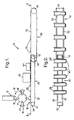
- Figure 1 is a schematic side elevation of apparatus for use in manufacturing cigarette cartons;
- Figure 2 is a plan view along line II-II in Figure 1 showing the disposition of carton blanks transported on the conveyors;
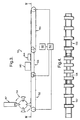
- Figure 3 is a schematic side elevation of another apparatus for use in manufacturing cigarette cartons;
- Figure 4 is a plan view along line IV-IV in Figure 3 showing the distribution of carton blanks transported on the conveyors; and
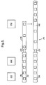
- Figure 5 is a schematic representation of yet another apparatus for use in manufacturing cigarette cartons.
- Referring to Figures 1 and 2, an
apparatus 10 for processing blanks in the manufacture of cartons for cigarettes comprises a cartonblank magazine 12 and ablank feeding device 14 for removing blanks from the magazine and feeding them one-by-one onto a conveyor system which is described in detail hereinbelow. - The
device 14 comprises a plurality ofarms 16 which are carried on adrum 17. The drum is rotatable about a fixed axis as indicated by thearrows 18 in Figure 1. Thearms 16 are pivotally mounted to thedrum 17 so as to be capable of moving back-and-forth in the circumferential direction of the drum and each carries asuction head 20 at its radially outermost end. Theheads 20 are provided with suction pads (not shown). - The motion of the
arms 16 relative to the drum is controlled by a cam system. The effect of the cam system is that as the suction pads of ahead 20 engage and grip the lowermost blank held in the magazine, the head rocks back in the direction opposite to the direction of rotation of thedrum 17 to facilitate removal of the blank from the magazine. Subsequently, as the arm is carried past the magazine, the head rocks forward (i.e, in the direction of rotation of the drum) under control of the cam system so as to resume a position in which its axis extends radially with respect to the drum. - The
device 14 is described in detail in WO 98/42604 A1. - The conveyor system comprises a
first conveyor 26 which is arranged to receive blanks from thedevice 14. To this end, the suction pads of thesuction heads 20 are deactivated as the heads approach theconveyor 26 so that the blanks are deposited on the conveyor; blanks deposited on the conveyor are indicated byreference numeral 28 in the figures. - The
conveyor 26 comprises twoendless belts 30 which are carried onpulleys 32 disposed at each end of the conveyor. In the usual way, one of thepulleys 32 is driven to cause movement of thebelts 30. Thebelts 30 carry battens, or bars, 34 which are known as pushers and extend in a direction transverse to the direction of travel of the belts. Thepushers 34 are evenly distributed along the length of the belts and serve to engage the trailing edge of theblanks 28 to ensure that the blanks are carried along the length of the conveyor (to the right in Figure 1). - An
adhesives applicator 40 is positioned adjacent theconveyor 26 to apply an adhesive, for example PVA, to a predetermined portion, or portions, of each blank. Theadhesives applicator 40 is of the wheel-type which is a device well known to those skilled in the art and accordingly will not be described in more detail herein. Suitable wheel-type applicators are described in US2615422, US3162546 and GB2093739. - A
folding machine 44 is disposed downstream of theadhesives applicator 40 and is arranged to fold anupper flap portion 46 of each blank 28 to a position (see the blank 28' in Figure 2) in which it is held by means of the adhesive applied by the applicator. - The
apparatus 10 further comprises asecond conveyor 50 which is positioned at the downstream end of thefirst conveyor 26. The construction of thesecond conveyor 50 corresponds to that of the first conveyor in that it comprises twoendless belts 52, twopulleys 54 andtransverse battens 56. - It will be noted that the
conveyors conveyor 26 to the upstream end of theconveyor 50 thereby maintaining a continuous flow ofblanks 28 away from thefolding machine 44. - The
conveyors - In more detail, the
first conveyor 26 is driven at a slower speed than thesecond conveyor 50; for example, the first conveyor may be driven so as to convey blanks at approximately one half the velocity at which they are conveyed on the second conveyor. One effect of this, as best seen in Figure 2, is that the spacing between the blanks (i.e, the pitch) on the two conveyors is different. In the case where the velocity of the first conveyor is one half the velocity of the second conveyor, the pitch for the blanks on the first conveyor is one half the pitch for the second conveyor. - Figures 3 and 4 show another
apparatus 110 for use in the manufacture of cigarette cartons. Parts of the apparatus which correspond to parts shown in Figures 1 and 2 have been given a similar reference numeral to which 100 has been added.
Theapparatus 110 comprises acarton magazine 112, ablank feeding device 114, afirst conveyor 126, anadhesives applicator 140, afolding machine 144 and asecond conveyor 150. - In addition to the
conveyors apparatus 110 comprises athird conveyor 152 which is disposed upstream of theconveyor 126. The construction of the third conveyor corresponds to that of thefirst conveyor 126 and will not therefore be described in detail. - A
motor drive 160 is provided for driving theconveyors motor drive 160 is connected to the conveyors by way of agearing system 162 which is arranged such that the individual conveyors do not operate at the same speed as described in more detail below. - As shown in Figure 3, the
blank feeding device 114 is arranged to feed carton blanks onto thethird conveyor 152. The blanks on theconveyor 152 are conveyed to theconveyor 126. Theconveyors conveyor 152 onto the upstream end of theconveyor 126. Whilst travelling along theconveyor 126 each of the blanks is subject to gluing and folding operations by theadhesives applicator 140 andfolding machine 144. - As with the
apparatus 10, thefirst conveyor 126 conveys blanks at a velocity which is approximately one half that at which they are conveyed by thesecond conveyor 150. Thethird conveyor 152 conveys the blanks at approximately the same velocity as thesecond conveyor 150. Thus whilst travelling along theapparatus 110, the blanks are first decelerated on reaching theconveyor 126 and subsequently accelerated back to the original conveying velocity on being transferred onto theconveyor 150 with consequent changes in pitch which are illustrated in Figure 4. Specifically, the pitch is reduced when the blanks are transferred onto the slower movingconveyor 126 and, since theconveyor 150 runs at the same speed as theconveyor 152, returned to the original spacing when they are transferred to theconveyor 150. - It will be appreciated that by providing a continuous conveyor system with adjacent conveyors which are operated at different speeds, it is possible to match the conveyed velocity and pitch of the blanks to the operating characteristics of the various processing machines which operate on the blanks. Where a wheel-type adhesives applicator is used, it is necessary that the velocity at which the blank is conveyed is substantially the same as the velocity of the periphery of the applicator wheel. The applicator wheel velocity is typically rather low and therefore in order to achieve a satisfactory throughput of blanks it is necessary to reduce the pitch of the blanks as much as possible. However, such a reduced pitch may not be suitable for subsequent processing operations on the blanks. Thus, the arrangements shown in Figures 1 and 3 provide the advantage that the pitch of the blanks can readily be increased downstream of the adhesives applicator to a pitch which is more suitable for subsequent operations.
- The
apparatus 110 has the additional advantage, as compared with theapparatus 10, that the blank feeding device is not restricted to an operating speed which is suited to the adhesives applicator. It will be appreciated that it is not essential for the operating speeds of theconveyors conveyor 126, theconveyor 150 might be operated at a higher speed than theconveyor 152. It will be appreciated that by operating theconveyor 150 at a higher speed than theconveyor 152, the pitch of the stream of blanks conveyed on theconveyor 150 will be greater than that of the stream conveyed by theconveyor 152 which may be desirable to facilitate processing operations to be performed on the blanks downstream of thefolding machine 144 and match the speed of theconveyor 152 to the operating speed of theblank feeding device 144. - A
third apparatus 210 for use in manufacturing cartons is schematically represented in Figure 5. Theapparatus 210 comprises twoconveyors carton blanks 216 from a blank feed device (not shown). - The
conveyors adhesives applicator apparatus 220 and afolding apparatus 222. The conveyors may be multi-belt conveyors (as shown in Figures 2 and 4) or simply have a single belt and in either case have pushers (not shown) for engaging the trailing edges of the blanks.Respective deadplates conveyors respective conveyors conveyors - A
transfer device 242 is provided adjacent the downstream end of theconveyor 238. The transfer device transfers carton blanks from theconveyor 238 to theconveyor 240 and may be a pusher unit which pushes the cartons in a direction transverse to the direction of travel of the conveyors or alternatively some form of pick-and-place device. Such apparatus for transferring parts between conveyors will be well known to those skilled in the art and will not therefore be described in detail herein. - The
conveyors blanks 216 at a velocity selected to suit the applicator wheels of theadhesives applicator apparatus 220. On reaching the downstream end of theconveyors respective deadplates respective conveyors conveyors conveyors conveyors conveyors - The
transfer device 242 transfers blanks from the downstream end of theconveyor 238 to theconveyor 240, inserting them into the spaces between the blanks on the latter conveyor. As shown, this has the effect of reducing the pitch of the stream of blanks on theconveyor 240 downstream of the transfer device. - It will be understood that by means of the
apparatus 210, two relatively slow moving streams of blanks may be combined to form a single fast moving stream. Thus, for example, theconveyors transfer device 242 theconveyor 240 is conveying 1000 blanks per minute. - It will be appreciated that the
apparatus 210 allows the combination of two streams of blanks moving at a relatively low speed which is governed by the adhesives applicator and/or the blank feeding devices into one fast moving stream thereby obtaining the benefit of a higher speed capability of apparatus further down the line in the carton making process. In this connection, it will be understood that theapparatus 210 may be simplified by positioning thefolding apparatus 222 downstream of thetransfer device 242 to operate on the combined flow of blanks conveyed by theconveyor 240. It will also be understood that by suitable selection of the speed of theconveyors conveyor 240 may be greater than the pitch of the streams of blanks on theconveyors - As an alternative to utilising deadplates and out of phase pushers, the out of phase relationship could be generated by having the
conveyors conveyors - It will be understood that even where the two
conveyors conveyor 238 into the spaces generated by increasing the pitch of the stream of blanks conveyed along the conveying path defined by theconveyors - The apparatus have been described in relation to the application of adhesives to carton blanks by means of wheel-type applicators. Although particularly suited to that purpose, the apparatus is considered equally suitable for use with alternative adhesives application devices such as, for example, spray applicators or extrusion ('slot die') coating devices.
- It will also be appreciated that although in the embodiments the conveyors are flat-belt conveyors, other conveyors, such as rotary drum conveyors or rotors, would also be suitable.
- It will be appreciated that instead of pushers, the conveyors may utilise a vacuum system to hold the blanks in the required position.
- It will be appreciated that instead of applying an adhesive, the apparatus may be used to apply an adhesives carrying element or elements to the blanks. For example, as a direct substitute for an adhesive, a double-sided sticky patch could be applied. Alternatively a hologram, coupon or a label carrying an adhesive on its rear face may be applied to the blanks. Alternatively the adhering element may adhere to the blank by virtue of an adhesive, which may be heat or pressure activated, carried by the blank.
- It will be appreciated that in its broader aspects the invention is applicable to processing situations other than the application of an adhesive to a carton blank in which it is desired to alter the pitch of the parts conveyed and/or merge parallel running streams of parts into a single stream.
Claims (11)
- Apparatus for use in processing packaging blanks, said apparatus comprising first conveying means for conveying said blanks, applying means for applying an adhesive or at least one adhesive element to each blank conveyed by said first conveying means, second conveying means arranged to receive said blanks from said first conveying means; characterised in that said first conveying means comprise two conveyors (212, 214) for conveying two respective streams of blanks (216), and said second conveying means comprise a first conveyor (240) for receiving the stream of blanks conveyed by one of said conveyors (212, 214) and a second conveyor (238) for receiving the said stream of blanks conveyed by the other of said two conveyors (212, 214), and blank transferring means (230, 232) are provided for transferring blanks between the said conveyors of said second conveying means, wherein at least said first conveyor (240) of said second conveying means is arranged to convey the blanks conveyed thereon at a conveying velocity which is greater than the conveying velocity of the respective one conveyor (212, 214) of said first conveying means, such that the stream of blanks conveyed by at least said first conveyor (240) of said second conveying means has a pitch greater than the respective stream of blanks conveyed by said one conveyor (212, 214), and said blank transferring means are adapted to insert the blanks conveyed by said second conveyor (238) into spaces between the blanks of the stream of blanks conveyed by said first conveyor (240).
- Apparatus as claimed in claim 1, characterised in that the conveyors (238, 240) of said second conveying means are arranged such that the respective streams of blanks conveyed thereon have an out-of-phase relationship, such that the respective streams of blanks are staggered with respect to one another.
- Apparatus as claimed in claim 1 or 2, characterised in that said first conveyor (240) and said second conveyor (238) are each arranged to accelerate the streams of blanks conveyed thereon to a conveying velocity greater than the conveying velocity of the respective conveyors (214, 212) of said first conveying means.
- Apparatus as claimed in any preceding claim, characterised in that each conveyor (238, 240) of said second conveying means comprises a plurality of substantially equally spaced apart members (56) arranged for engaging a trailing edge of the blanks conveyed thereon.
- Apparatus as claimed in any preceding claim, characterised in that said blank transferring means is arranged to insert the blanks conveyed by said second conveyor (238) into said spaces between the stream of blanks conveyed by said first conveyor (240) so as to provide a stream of blanks comprised alternately of blanks from said first conveyor and said second conveyor.
- Apparatus as claimed in any preceding claim, characterised in that said blank transferring means is arranged to push blanks from said second conveyor (238) onto said first conveyor (240).
- Apparatus as claimed in any preceding claim, characterised in that said first conveyor (240) and said second conveyor (238) are disposed in a substantially parallel spaced apart relationship and said blank transferring means is arranged to move blanks from said second conveyor to said first conveyor by moving said blanks in a direction normal to the direction of travel of said first conveyor and said second conveyor.
- Apparatus as claimed in any preceding claim, characterised by respective dead-plates (230, 232) disposed between said conveyors of said first conveying means and said conveyors of said second conveying means.
- Apparatus as claimed in any preceding claim, characterised in that said applying means (220) comprises a plurality of applicator wheels for applying an adhesive arranged such that each conveyor of said first conveyor means (212, 214) has at least one applicator wheel associated therewith.
- Apparatus as claimed in any preceding claim, characterised by blank feeding means for feeding blanks one-by-one onto each conveyor (212, 214) of said first conveyor means to form said respective streams of carton blanks (216).
- Apparatus as claimed in claim 10, characterised in that said blank feeding means and said conveyors (212, 214) of said first conveying means are arranged such that said respective streams of blanks have substantially the same pitch and are in an in-phase relationship.
Applications Claiming Priority (3)
| Application Number | Priority Date | Filing Date | Title |
|---|---|---|---|
| GBGB9803964.7A GB9803964D0 (en) | 1998-02-24 | 1998-02-24 | Processing blanks in the manufacture of packaging |
| GB9803964 | 1998-02-24 | ||
| PCT/GB1999/000547 WO1999043552A1 (en) | 1998-02-24 | 1999-02-23 | Processing blanks in the manufacture of packaging |
Publications (2)
| Publication Number | Publication Date |
|---|---|
| EP1060100A1 EP1060100A1 (en) | 2000-12-20 |
| EP1060100B1 true EP1060100B1 (en) | 2006-10-11 |
Family
ID=10827570
Family Applications (1)
| Application Number | Title | Priority Date | Filing Date |
|---|---|---|---|
| EP99906342A Expired - Lifetime EP1060100B1 (en) | 1998-02-24 | 1999-02-23 | Processing blanks in the manufacture of packaging |
Country Status (6)
| Country | Link |
|---|---|
| US (1) | US6855100B1 (en) |
| EP (1) | EP1060100B1 (en) |
| CN (1) | CN1123494C (en) |
| DE (1) | DE69933546T2 (en) |
| GB (1) | GB9803964D0 (en) |
| WO (1) | WO1999043552A1 (en) |
Families Citing this family (13)
| Publication number | Priority date | Publication date | Assignee | Title |
|---|---|---|---|---|
| ATE494221T1 (en) * | 2006-03-08 | 2011-01-15 | Manroland Ag | APPLICATION DEVICE FOR ELECTRONIC COMPONENTS |
| ITBO20120031A1 (en) * | 2012-01-26 | 2012-04-26 | Gd Spa | WRAPPING MACHINE AND WRAPPING METHOD TO CREATE A PACKAGE OF SMOKE ITEMS WITH SLIDING OPENING AND WITH HINGED AND BOILED LID. |
| US20140196403A1 (en) * | 2013-01-11 | 2014-07-17 | Stork Fabricators, Inc. | Automated Systems and Methods for Combining Cards and Products |
| US8812152B1 (en) | 2013-02-22 | 2014-08-19 | TamiCare, Ltd. | Method and apparatus for changing carriage speed on a closed-loop track |
| EP2976279B1 (en) * | 2013-03-18 | 2018-07-25 | Bobst Mex Sa | Device for ejecting a flat object during conveying |
| CN103144798B (en) * | 2013-03-22 | 2015-01-14 | 龙岩烟草工业有限责任公司 | Glue cylinder anti-loosening locking device of cigarette carton packaging machine and packaging machine |
| CA2823591A1 (en) * | 2013-08-14 | 2015-02-14 | Beaver Machine Corporation | Product singulating system and apparatus |
| JP6644677B2 (en) * | 2013-10-08 | 2020-02-12 | ボブスト メックス ソシエテ アノニムBobst Mex SA | Module and machine for processing flat objects provided with the module |
| WO2017037675A1 (en) * | 2015-09-02 | 2017-03-09 | N&W Global Vending S.P.A. | Pod dispenser |
| ITUB20153402A1 (en) * | 2015-09-03 | 2017-03-03 | N&W Global Vending S P A | DISPENSER OF PODS |
| CN109532092B (en) * | 2018-11-12 | 2021-01-26 | 江苏联通纪元印务股份有限公司 | Integrated cigarette case forming mechanism |
| CN111152988B (en) * | 2019-12-27 | 2021-07-27 | 安徽虹源医药包装有限公司 | Automatic bonding device of packing carton |
| IT202200004976A1 (en) * | 2022-03-15 | 2023-09-15 | Plusline S R L | Case packing machine. |
Family Cites Families (19)
| Publication number | Priority date | Publication date | Assignee | Title |
|---|---|---|---|---|
| GB1021603A (en) | 1900-01-01 | |||
| US2615422A (en) | 1950-08-01 | 1952-10-28 | Hall Printing Co W F | Gluing device |
| GB963360A (en) | 1961-06-01 | 1964-07-08 | Albert George Jeffreys | Apparatus for applying patches of adhesive to blanks in automatic machines |
| CA899615A (en) * | 1970-08-25 | 1972-05-09 | Somerville Industries Limited | Sealing compound applicator |
| US3772971A (en) * | 1971-05-27 | 1973-11-20 | Taylor M L | Batch stacker |
| CH553709A (en) * | 1973-07-09 | 1974-09-13 | Sig Schweiz Industrieges | CONVEYOR SYSTEM WITH DEVICE FOR SEPARATING OBJECTS INTO MUTUAL CONTACT ON AN INPUT CONVEYOR. |
| US4006831A (en) * | 1974-03-06 | 1977-02-08 | Electra Food Machinery, Inc. | Automatic tortilla counter and stacker |
| DE3108089C2 (en) | 1981-03-04 | 1987-01-15 | Focke & Co, 2810 Verden | Device for applying glue to packaging rags |
| FR2527573A1 (en) * | 1982-05-27 | 1983-12-02 | Cuir Sa | METHOD AND DEVICE FOR TRANSFERRING A SHEET OF MATERIAL FROM ONE ASSEMBLY TO ANOTHER |
| CH664343A5 (en) | 1985-11-11 | 1988-02-29 | Bobst Sa | DEVICE FOR FORMING SEPARATE LOTS OF FLAT OBJECTS FROM A TABLE OF MOVING OBJECTS. |
| GB2195926B (en) | 1986-08-08 | 1991-01-02 | Gd Spa | Device for applying adhesive on to sheets of packing material |
| US5092827A (en) * | 1989-09-28 | 1992-03-03 | International Paper Box Machine Co., Inc. | Apparatus for folding paper boxes |
| US5230686A (en) * | 1992-08-19 | 1993-07-27 | International Paper Box Machine Co., Inc. | Apparatus for folding paper boxes |
| DE4332186C2 (en) * | 1993-09-22 | 1996-09-12 | Condex Maschinenbau Gmbh | Method and device for laminating flat material blanks |
| GB2282364A (en) * | 1993-09-29 | 1995-04-05 | Langston Corp | Spacing fed articles, e.g. box blanks |
| DE4439198A1 (en) * | 1994-11-06 | 1996-05-09 | Klett Alfred | Device for processing a blank conveyed along a conveying path with a predetermined conveying speed |
| US5853360A (en) * | 1995-06-16 | 1998-12-29 | J & L Development, Inc. | Method and apparatus for producing a gusseted container |
| DE19529139A1 (en) | 1995-08-08 | 1997-02-13 | Focke & Co | Device for the orderly transport of packages, in particular in connection with a labeler |
| IT1285513B1 (en) | 1996-02-02 | 1998-06-08 | Gd Spa | METHOD FOR FEEDING BLANKS INTO A CIGARETTE PACKING MACHINE |
-
1998
- 1998-02-24 GB GBGB9803964.7A patent/GB9803964D0/en not_active Ceased
-
1999
- 1999-02-23 WO PCT/GB1999/000547 patent/WO1999043552A1/en not_active Ceased
- 1999-02-23 EP EP99906342A patent/EP1060100B1/en not_active Expired - Lifetime
- 1999-02-23 CN CN99804772A patent/CN1123494C/en not_active Expired - Fee Related
- 1999-02-23 DE DE69933546T patent/DE69933546T2/en not_active Expired - Fee Related
-
2000
- 2000-08-22 US US09/642,585 patent/US6855100B1/en not_active Expired - Fee Related
Also Published As
| Publication number | Publication date |
|---|---|
| CN1296453A (en) | 2001-05-23 |
| CN1123494C (en) | 2003-10-08 |
| WO1999043552A1 (en) | 1999-09-02 |
| DE69933546D1 (en) | 2006-11-23 |
| EP1060100A1 (en) | 2000-12-20 |
| DE69933546T2 (en) | 2007-01-18 |
| GB9803964D0 (en) | 1998-04-22 |
| US6855100B1 (en) | 2005-02-15 |
Similar Documents
| Publication | Publication Date | Title |
|---|---|---|
| US6855100B1 (en) | Processing blanks in the manufacture of packaging | |
| NL1006370C2 (en) | Conveyor for accelerating a range of products. | |
| US10766644B2 (en) | Apparatus and method for forming a carton | |
| US4714515A (en) | Straight line container labeling apparatus | |
| US5082520A (en) | Automatic high-speed labeling machine employing various linear and rotational speeds of the container | |
| US3955481A (en) | Apparatus for adhering traveling strip material to folded blank boxes | |
| EP2755906B1 (en) | Carton feeding system | |
| GB2225979A (en) | Method and apparatus for securing clasps to envelopes | |
| US5024717A (en) | Labelling apparatus | |
| EP3263470B1 (en) | Labelling group and method for applying a plurality of labels onto respective articles | |
| JP3991120B2 (en) | Transport system for flat shipments | |
| EP0711719B1 (en) | Equally spaced product conveying method and line | |
| JP4580381B2 (en) | Method and apparatus for folding an onsert and pasting it on a consumer product | |
| US7234696B2 (en) | Method of, and apparatus for, handling blanks, in particular coupons | |
| GB2285964A (en) | Interruption of labelling | |
| CA1222481A (en) | Labeling machines | |
| EP0795472A1 (en) | Product wrapping method | |
| US5287954A (en) | Device for equally-spaced in-line transportation of randomly arranged incoming products | |
| US3998447A (en) | Method and apparatus for folding flaps of a sanitary pad | |
| US5112430A (en) | Apparatus for applying a sheet to a substrate | |
| US5309697A (en) | Chewing gum packaging machine | |
| US12534259B2 (en) | Method and apparatus for forming groups of absorbent sanitary articles | |
| JP3793232B2 (en) | Method and apparatus for conveying printed material stream | |
| GB2263894A (en) | Wrapping labeling device | |
| US3974748A (en) | Apparatus for collating sheet like elements |
Legal Events
| Date | Code | Title | Description |
|---|---|---|---|
| PUAI | Public reference made under article 153(3) epc to a published international application that has entered the european phase |
Free format text: ORIGINAL CODE: 0009012 |
|
| 17P | Request for examination filed |
Effective date: 20000821 |
|
| AK | Designated contracting states |
Kind code of ref document: A1 Designated state(s): DE GB IT |
|
| 17Q | First examination report despatched |
Effective date: 20020531 |
|
| GRAP | Despatch of communication of intention to grant a patent |
Free format text: ORIGINAL CODE: EPIDOSNIGR1 |
|
| GRAS | Grant fee paid |
Free format text: ORIGINAL CODE: EPIDOSNIGR3 |
|
| GRAA | (expected) grant |
Free format text: ORIGINAL CODE: 0009210 |
|
| AK | Designated contracting states |
Kind code of ref document: B1 Designated state(s): DE GB IT |
|
| PG25 | Lapsed in a contracting state [announced via postgrant information from national office to epo] |
Ref country code: IT Free format text: LAPSE BECAUSE OF FAILURE TO SUBMIT A TRANSLATION OF THE DESCRIPTION OR TO PAY THE FEE WITHIN THE PRESCRIBED TIME-LIMIT;WARNING: LAPSES OF ITALIAN PATENTS WITH EFFECTIVE DATE BEFORE 2007 MAY HAVE OCCURRED AT ANY TIME BEFORE 2007. THE CORRECT EFFECTIVE DATE MAY BE DIFFERENT FROM THE ONE RECORDED. Effective date: 20061011 |
|
| REG | Reference to a national code |
Ref country code: GB Ref legal event code: FG4D |
|
| REF | Corresponds to: |
Ref document number: 69933546 Country of ref document: DE Date of ref document: 20061123 Kind code of ref document: P |
|
| PLBE | No opposition filed within time limit |
Free format text: ORIGINAL CODE: 0009261 |
|
| STAA | Information on the status of an ep patent application or granted ep patent |
Free format text: STATUS: NO OPPOSITION FILED WITHIN TIME LIMIT |
|
| 26N | No opposition filed |
Effective date: 20070712 |
|
| PGFP | Annual fee paid to national office [announced via postgrant information from national office to epo] |
Ref country code: DE Payment date: 20090216 Year of fee payment: 11 |
|
| PGFP | Annual fee paid to national office [announced via postgrant information from national office to epo] |
Ref country code: GB Payment date: 20090226 Year of fee payment: 11 |
|
| PGFP | Annual fee paid to national office [announced via postgrant information from national office to epo] |
Ref country code: IT Payment date: 20090122 Year of fee payment: 11 |
|
| GBPC | Gb: european patent ceased through non-payment of renewal fee |
Effective date: 20100223 |
|
| PG25 | Lapsed in a contracting state [announced via postgrant information from national office to epo] |
Ref country code: DE Free format text: LAPSE BECAUSE OF NON-PAYMENT OF DUE FEES Effective date: 20100901 |
|
| PG25 | Lapsed in a contracting state [announced via postgrant information from national office to epo] |
Ref country code: GB Free format text: LAPSE BECAUSE OF NON-PAYMENT OF DUE FEES Effective date: 20100223 Ref country code: IT Free format text: LAPSE BECAUSE OF NON-PAYMENT OF DUE FEES Effective date: 20100223 |