EP1059197A1 - Holmelement zur Kraftabstützung in einem Fahrzeug - Google Patents
Holmelement zur Kraftabstützung in einem Fahrzeug Download PDFInfo
- Publication number
- EP1059197A1 EP1059197A1 EP00111846A EP00111846A EP1059197A1 EP 1059197 A1 EP1059197 A1 EP 1059197A1 EP 00111846 A EP00111846 A EP 00111846A EP 00111846 A EP00111846 A EP 00111846A EP 1059197 A1 EP1059197 A1 EP 1059197A1
- Authority
- EP
- European Patent Office
- Prior art keywords
- profile
- force
- axis
- center
- spar
- Prior art date
- Legal status (The legal status is an assumption and is not a legal conclusion. Google has not performed a legal analysis and makes no representation as to the accuracy of the status listed.)
- Granted
Links
- 230000005484 gravity Effects 0.000 claims abstract description 6
- 238000005452 bending Methods 0.000 description 5
- 238000010586 diagram Methods 0.000 description 2
- 238000013016 damping Methods 0.000 description 1
- 230000003247 decreasing effect Effects 0.000 description 1
- 230000001934 delay Effects 0.000 description 1
- 230000001419 dependent effect Effects 0.000 description 1
- 230000000694 effects Effects 0.000 description 1
- 238000009472 formulation Methods 0.000 description 1
- 238000004519 manufacturing process Methods 0.000 description 1
- 239000000203 mixture Substances 0.000 description 1
- 238000011144 upstream manufacturing Methods 0.000 description 1
Images
Classifications
-
- B—PERFORMING OPERATIONS; TRANSPORTING
- B60—VEHICLES IN GENERAL
- B60N—SEATS SPECIALLY ADAPTED FOR VEHICLES; VEHICLE PASSENGER ACCOMMODATION NOT OTHERWISE PROVIDED FOR
- B60N2/00—Seats specially adapted for vehicles; Arrangement or mounting of seats in vehicles
- B60N2/68—Seat frames
Definitions
- the present invention relates to a spar element for Support of a force in a vehicle, in particular for Support of an upper, integrated in the area of a backrest Belt point in a belt integral seat, consisting from a profile element with a rigidly attached first profile end and a free second profile end, at the second end of the profile a force attack for the in Direction approximately perpendicular to a longitudinal axis of the profile acting force axis is arranged.
- Such spar elements are known. Especially for the preferred one Use case to support a seat belt point in a so-called belt integral seat, where an upper belt deflection point or a belt retractor in the upper area of a seat backrest is integrated, high demands are made on the respective spar element regarding the bending stiffness. In order to avoid, that the spar element collapses under high tensile loads, are usually reinforced designs, in particular in the form of closed box profiles, used, but what is disadvantageously the weight and the Costs increased.
- the present invention is based on the object To create spar element, which is characterized by low weight and is characterized by low costs, but nevertheless sufficient durability and secure power support guaranteed.
- the profile element is formed by an open hollow profile, so that - related to a cross-sectional plane through the force application - his center of thrust against his Center of gravity is offset, with the force attack opposite the thrust center is arranged so offset that when applied with a force up to a certain one Amount of force a torsion of the profile element takes place as far as until the force axis through the center of thrust runs. This will start at the certain amount of force further increasing force only the profile element Bending stressed.
- the spar element relative to forces below the specified force soft, d. H. there should be elastic torsion, which a soft, elastic "damping" of these relatively low forces is reached.
- Torsional range results from the force application Lever arm that changes due to torsion, so despite increasing force the torsional moment goes to zero.
- the spar element suddenly harder because further torsion is impossible and the profile element only bends is claimed.
- there is a high degree of flexural rigidity in front Compared to the previously common rigid profiles an increased breaking force due to the "upstream" torsion reached.
- the invention thus leads to an increased resilience with particularly low weight and low manufacturing costs.
- the invention also works in one special comfort.
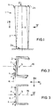
- a spar element 1 consists of a Profile element 2 with a rigidly fastened first Profile end 2a and a free second profile end 2b.
- a force attack 4 for a force F is arranged, this force F in the direction a force axis K acts approximately to the longitudinal axis 6 of the profile runs vertically.
- the thrust center T offset from its center of gravity S. is arranged outside the profile (based on a through the force application point 4 cross-sectional plane).
- the force application is 4 arranged so offset with respect to the thrust center T that when the profile element 2 is acted upon Force attack 4 with a force F up to a certain one Amount of force a relatively soft elastic torsion of the Profile element 2 takes place (see Fig. 2 and 3) until the Force axis K runs through the center of thrust T (Fig. 3).
- the application of force is 4 according to the invention, on the one hand, starting from the center of gravity S beyond the thrust center T and on the other hand also offset in the direction in which the force F works.
- the profile element 2 essentially over its longitudinal extent constant cross-sectional shape and size.
- the profile element 2 based on the first profile end 2a a in the longitudinal direction up to the second profile end 2b, preferably continuously changing, in particular has reducing cross-sectional size. It is a "quasi-conical" shape.
- the profile element 2 its free second profile end 2b rigid with a lid-like End element 8 may be connected. This is what it is about is a plate that closes the profile in the longitudinal direction.
- the deformation behavior can be achieved by both described features be influenced, in particular this makes the torsion stiffer.
- the profile element 2 can have any open cross section have, for example, as shown an im essential U-shaped profile cross-section. It can also act as a C-shaped cross section.
- Profile element 2 in relation to a common vehicle coordinate system (cf. 1 to 4, the coordinates X, Y and Z) Profile element 2 in a vehicle preferably aligned in such a way that a through the profile opening Profile transverse axis 16 (Fig. 3) approximately perpendicular to that of Vehicle longitudinal axis X corresponding force axis K runs.
- the transverse profile axis 16 corresponds approximately to the transverse vehicle axis Y.
- the profile longitudinal axis corresponds to 6 preferably about the vehicle vertical axis Z.
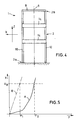
- FIG. 5 shows the bending deformation in the direction X as a function of the force F.
- a curve A illustrates the basic course of a spar element 1 according to the invention.
- the line of force initially runs relatively flat starting from the zero point. This is the area where torsion mainly occurs.
- the force axis K passing through the thrust center T (FIG. 3)
- the characteristic curve rises steeply.
- a characteristic curve B of a rigid full profile or closed hollow profile is drawn in dashed lines, which immediately has a steep linear course starting from the zero point.
- Such a known profile breaks at fracture deformation X B , which occurs at a force F 1 .
- the characteristic curve A of the profile element according to the invention achieves this critical deformation X B only at a force F 2 which is greater than F 1 .
- the invention is not based on the illustrated and described Embodiments limited, but also includes all designs having the same effect in the sense of the invention. Furthermore, the invention is not yet based on the Claim 1 defined combination of features limited, but can also be by any other combination of certain characteristics of all of the individual characteristics disclosed be defined. This means that basically practically every single feature of claim 1 omitted or by at least one elsewhere in the registration disclosed individual feature can be replaced. To that extent is claim 1 only as a first attempt at formulation to understand for an invention.
Landscapes
- Engineering & Computer Science (AREA)
- Aviation & Aerospace Engineering (AREA)
- Transportation (AREA)
- Mechanical Engineering (AREA)
- Springs (AREA)
- Chairs For Special Purposes, Such As Reclining Chairs (AREA)
- Body Structure For Vehicles (AREA)
Abstract
Description
- Fig. 1
- eine schematische Vorderansicht einer möglichen Ausführungsform eines erfindungsgemäßen Holmelementes in einem unverformten Zustand ohne Kraftbeaufschlagung,
- Fig. 2
- eine Draufsicht in Pfeilrichtung II gemäß Fig. 1,
- Fig. 3
- eine Ansicht analog zu Fig. 2 im belastungsbedingt verformten Zustand,
- Fig. 4
- eine Seitenansicht im verformten Zustand gemäß Pfeil IV in Fig. 3 bzw. Fig. 1 und
- Fig. 5
- ein schematisches Kräftediagramm.
Claims (10)
- Holmelement (1) zur Abstützung einer Kraft (F) in einem Fahrzeug, insbesondere zur Abstützung eines oberen, im Bereich einer Rückenlehne integrierten Gurtpunktes bei einem Gurtintegralsitz, bestehend aus einem Profilelement (2) mit einem starr zu befestigenden ersten Profilende (2a) und einem freien zweiten Profilende (2b), wobei am zweiten Profilende (2b) ein Kraftangriff (4) für die in Richtung einer zur Profil-Längsachse (6) etwa senkrecht verlaufenden Kraftachse (K) wirkende Kraft (F) angeordnet ist,
dadurch gekennzeichnet,
daß das Profilelement (2) von einem offenen Hohlprofil gebildet ist, so daß - bezogen auf eine durch den Kraftangriff (4) verlaufende Querschnittsebene - sein Schubmittelpunkt (T) gegenüber seinem Schwerpunkt (S) versetzt ist, wobei der Kraftangriff (4) gegenüber dem Schubmittelpunkt (T) derart versetzt angeordnet ist, daß bei Beaufschlagung mit einer Kraft (F) bis zu einem bestimmten Kraftbetrag eine Torsion des Profilelementes (2) um eine Längsachse soweit erfolgt, bis die Kraftachse (K) durch den Schubmittelpunkt (T) verläuft. - Holmelement nach Anspruch 1,
dadurch gekennzeichnet,
daß der Kraftangriff (4) einerseits ausgehend vom Schwerpunkt (S) über den Schubmittelpunkt (T) hinaus und andererseits in die Richtung versetzt ist, in der die Kraft (F) wirkt. - Holmelement nach Anspruch 1 oder 2,
dadurch gekennzeichnet,
daß das Profilelement (2) eine derart um eine Längsachse in sich derart vortordierte Form aufweist, daß durch die Kraftbeaufschlagung bei Erreichen des bestimmten Kraftbetrages, wobei die Kraftachse (K) durch den Schubmittelpunkt (T) verläuft, die Vortorsion im wesentlichen beseitigt ist. - Holmelement nach einem der Ansprüche 1 bis 3,
dadurch gekennzeichnet,
daß das Profilelement (2) ausgehend von dem ersten Profilende (2a) eine sich in Längsrichtung bis zu dem zweiten Profilende (2b) vorzugsweise stetig ändernde, insbesondere verkleinernde Querschnittsgröße aufweist. - Holmelement nach einem der Ansprüche 1 bis 4,
dadurch gekennzeichnet,
daß das Profilelement (2) an seinem freien zweiten Profilende (2b) in Längsrichtung gesehen starr mit einem deckelartigen Abschlußelement (8) verbunden ist. - Holmelement nach einem der Ansprüche 1 bis 5,
dadurch gekennzeichnet,
daß das Profilelement (2) auf seiner offenen Längsseite zwei gegenüberliegende Profilschenkel (10, 12) aufweist, die an mindestens einer Stelle der Profil-Längserstreckung über eine Querverbindung (14) starr miteinander verbunden sind. - Holmelement nach Anspruch 6,
dadurch gekennzeichnet,
daß die Profilschenkel (10, 12) über mehrere in Profil-Längsrichtung mit Abstand verteilt angeordnete Querverbindungen (14) verbunden sind. - Holmelement nach einem der Ansprüche 1 bis 7,
dadurch gekennzeichnet,
daß das Profilelement (2) einem im wesentlichen U-förmigen oder C-förmigen Profilquerschnitt aufweist. - Holmelement nach einem der Ansprüche 1 bis 8,
dadurch gekennezcihnet,
daß das Profilelement (2) in seinem in einem Fahrzg montierten Zustand - bezogen auf ein übliches Fahrzeug-Koordinatensystem - derart ausgerichtet ist, daß eine durch die sich in Längsrichtung erstreckende Profilöffnung verlaufende Profil-Querachse (16) etwa senkrecht zu der der Fahrzeug-Längsachse (X) entsprechenden Kraftachse (K) verläuft. - Holmelement nach Anspruch 9,
dadurch gekennzeichnet,
daß die Profil-Querachse (16) etwa der Fahrzeug-Querachse (Y) entspricht und/oder daß die Profil-Längsachse (6) etwa der Fahrzeug-Vertikalachse (Z) entspricht.
Applications Claiming Priority (2)
| Application Number | Priority Date | Filing Date | Title |
|---|---|---|---|
| DE29910063U DE29910063U1 (de) | 1999-06-09 | 1999-06-09 | Holmelement zur Kraftabstützung in einem Fahrzeug |
| DE29910063U | 1999-06-09 |
Publications (2)
| Publication Number | Publication Date |
|---|---|
| EP1059197A1 true EP1059197A1 (de) | 2000-12-13 |
| EP1059197B1 EP1059197B1 (de) | 2003-08-27 |
Family
ID=8074566
Family Applications (1)
| Application Number | Title | Priority Date | Filing Date |
|---|---|---|---|
| EP00111846A Expired - Lifetime EP1059197B1 (de) | 1999-06-09 | 2000-06-07 | Holmelement zur Kraftabstützung in einem Fahrzeug |
Country Status (2)
| Country | Link |
|---|---|
| EP (1) | EP1059197B1 (de) |
| DE (2) | DE29910063U1 (de) |
Cited By (1)
| Publication number | Priority date | Publication date | Assignee | Title |
|---|---|---|---|---|
| DE102008023943B4 (de) * | 2008-05-13 | 2012-03-15 | Keiper Gmbh & Co. Kg | Fahrzeugsitz mit Beschlägen |
Citations (6)
| Publication number | Priority date | Publication date | Assignee | Title |
|---|---|---|---|---|
| US4804226A (en) * | 1986-07-18 | 1989-02-14 | Keiper Recaro Gmbh. & Co. | Deformation-resistant frame for seats of motor vehicles |
| EP0709250A2 (de) * | 1994-10-17 | 1996-05-01 | Atoma International Inc. | Sitzarmatur für Kraftfahrzeuge |
| DE29622299U1 (de) * | 1996-12-21 | 1997-03-06 | Bertrand Faure Sitztechnik GmbH & Co. KG, 31655 Stadthagen | Rückenlehnenrahmen für einen gurtintegrierten Fahrzeugsitz |
| US5645316A (en) * | 1995-07-03 | 1997-07-08 | Bertrand Faure Equipements Sa | Vehicle seatback frame, and a seat including such a frame |
| DE19603946A1 (de) * | 1996-02-05 | 1997-08-07 | Daimler Benz Ag | Fahrzeugsitz |
| US5722731A (en) * | 1995-10-25 | 1998-03-03 | Chang; Chung L. | Vehicle seat and seat belt arrangement |
-
1999
- 1999-06-09 DE DE29910063U patent/DE29910063U1/de not_active Expired - Lifetime
-
2000
- 2000-06-07 DE DE50003416T patent/DE50003416D1/de not_active Expired - Fee Related
- 2000-06-07 EP EP00111846A patent/EP1059197B1/de not_active Expired - Lifetime
Patent Citations (6)
| Publication number | Priority date | Publication date | Assignee | Title |
|---|---|---|---|---|
| US4804226A (en) * | 1986-07-18 | 1989-02-14 | Keiper Recaro Gmbh. & Co. | Deformation-resistant frame for seats of motor vehicles |
| EP0709250A2 (de) * | 1994-10-17 | 1996-05-01 | Atoma International Inc. | Sitzarmatur für Kraftfahrzeuge |
| US5645316A (en) * | 1995-07-03 | 1997-07-08 | Bertrand Faure Equipements Sa | Vehicle seatback frame, and a seat including such a frame |
| US5722731A (en) * | 1995-10-25 | 1998-03-03 | Chang; Chung L. | Vehicle seat and seat belt arrangement |
| DE19603946A1 (de) * | 1996-02-05 | 1997-08-07 | Daimler Benz Ag | Fahrzeugsitz |
| DE29622299U1 (de) * | 1996-12-21 | 1997-03-06 | Bertrand Faure Sitztechnik GmbH & Co. KG, 31655 Stadthagen | Rückenlehnenrahmen für einen gurtintegrierten Fahrzeugsitz |
Cited By (1)
| Publication number | Priority date | Publication date | Assignee | Title |
|---|---|---|---|---|
| DE102008023943B4 (de) * | 2008-05-13 | 2012-03-15 | Keiper Gmbh & Co. Kg | Fahrzeugsitz mit Beschlägen |
Also Published As
| Publication number | Publication date |
|---|---|
| DE50003416D1 (de) | 2003-10-02 |
| EP1059197B1 (de) | 2003-08-27 |
| DE29910063U1 (de) | 2000-10-12 |
Similar Documents
| Publication | Publication Date | Title |
|---|---|---|
| DE69201446T2 (de) | Energie-Dämpfer, so wie Stützstruktur für einen Luftfahrzeugsitz mit diesem Dämpfer und Sitz mit dieser Struktur. | |
| EP1493634B1 (de) | Airbagmodul mit Gehäuse für die Aufnahme mindestens eines Gasgenerators und mindestens eines Gassacks | |
| WO2019170547A1 (de) | Längsverstellvorrichtung für einen fahrzeugsitz mit einer bodenschiene, einer längsverschiebbaren sitzschiene und einer arretiereinheit | |
| DE10026119B4 (de) | Elastische Anordnung | |
| WO2022233761A1 (de) | Höhenverstelleinrichtung eines fahrzeugsitzes | |
| DE29800909U1 (de) | Baugruppe aus einem Gurtschloß, einem Befestigungsbeschlag sowie einem Kraftbegrenzer | |
| DE19647167C2 (de) | Verankerungsvorrichtung eines Umlenkbeschlags eines Drei-Punkt-Sicherheitsgurts | |
| EP2625062A2 (de) | Längsverstelleinrichtung für einen kraftfahrzeugsitz | |
| DE112008001976B4 (de) | Einheit zum Absorbieren von Energie mit zwei Absorptionsvorrichtungen | |
| DE102016217405B3 (de) | Energieabsorber für einen fahrzeugsitz sowie lineareinsteller für einen fahrzeugsitz mit einem energieabsorber | |
| DE112006001270B4 (de) | Lenkgetriebe | |
| DE102018208194B4 (de) | Befestigungselement zur Befestigung eines Scheinwerfers an einem Längsträger in einem Vorderwagen eines Kraftfahrzeuges sowie Anordnung eines Befestigungselements in einem Vorderwagen eines Kraftfahrzeuges | |
| DE10135627B4 (de) | Verriegelungsvorrichtung für einen Fahrzeugsitz | |
| EP1498299B1 (de) | Sitzschienenpaar für einen Fahrzeugsitz | |
| EP1059197B1 (de) | Holmelement zur Kraftabstützung in einem Fahrzeug | |
| DE69902294T2 (de) | Stossfänger- befestigungsvorrichtung für kraftfahrzeuge | |
| EP4474228A1 (de) | Fahrzeugsitz mit gurtsystem | |
| DE10142994A1 (de) | Längseinsteller für einen Fahrzeugsitz | |
| DE102018219905A1 (de) | Hilfsrahmen für ein Kraftfahrzeug | |
| DE19735753A1 (de) | Drehstabanordnung | |
| DE19926843B4 (de) | Längsführung für einen Fahrzeugsitz mit einem Kanalhohlraum | |
| EP0552859A1 (de) | Schraubendruckfederanordnung | |
| EP1517814A1 (de) | Stossfängertragstruktur eines kraftfahrzeuges | |
| WO2007031268A1 (de) | Optimiertes aufprallsystem für 10°-lastfall | |
| DE102023108497B4 (de) | Aus zumindest zwei Komponenten zusammengesetzter als Instrumententafelträger ausgelegter Querträger sowie Verwendung einer Überlappanordnung in einem solchen Querträger |
Legal Events
| Date | Code | Title | Description |
|---|---|---|---|
| PUAI | Public reference made under article 153(3) epc to a published international application that has entered the european phase |
Free format text: ORIGINAL CODE: 0009012 |
|
| AK | Designated contracting states |
Kind code of ref document: A1 Designated state(s): DE FR GB IT |
|
| AX | Request for extension of the european patent |
Free format text: AL;LT;LV;MK;RO;SI |
|
| 17P | Request for examination filed |
Effective date: 20001023 |
|
| EL | Fr: translation of claims filed | ||
| GBC | Gb: translation of claims filed (gb section 78(7)/1977) | ||
| AKX | Designation fees paid |
Free format text: DE FR GB IT |
|
| 17Q | First examination report despatched |
Effective date: 20020701 |
|
| GRAH | Despatch of communication of intention to grant a patent |
Free format text: ORIGINAL CODE: EPIDOS IGRA |
|
| GRAH | Despatch of communication of intention to grant a patent |
Free format text: ORIGINAL CODE: EPIDOS IGRA |
|
| GRAA | (expected) grant |
Free format text: ORIGINAL CODE: 0009210 |
|
| AK | Designated contracting states |
Designated state(s): DE FR GB IT |
|
| REG | Reference to a national code |
Ref country code: GB Ref legal event code: FG4D Free format text: NOT ENGLISH |
|
| REF | Corresponds to: |
Ref document number: 50003416 Country of ref document: DE Date of ref document: 20031002 Kind code of ref document: P |
|
| GBT | Gb: translation of ep patent filed (gb section 77(6)(a)/1977) |
Effective date: 20031118 |
|
| ET | Fr: translation filed | ||
| PLBE | No opposition filed within time limit |
Free format text: ORIGINAL CODE: 0009261 |
|
| STAA | Information on the status of an ep patent application or granted ep patent |
Free format text: STATUS: NO OPPOSITION FILED WITHIN TIME LIMIT |
|
| 26N | No opposition filed |
Effective date: 20040528 |
|
| PGFP | Annual fee paid to national office [announced via postgrant information from national office to epo] |
Ref country code: FR Payment date: 20050512 Year of fee payment: 6 |
|
| PGFP | Annual fee paid to national office [announced via postgrant information from national office to epo] |
Ref country code: GB Payment date: 20050516 Year of fee payment: 6 |
|
| PGFP | Annual fee paid to national office [announced via postgrant information from national office to epo] |
Ref country code: DE Payment date: 20050630 Year of fee payment: 6 |
|
| PG25 | Lapsed in a contracting state [announced via postgrant information from national office to epo] |
Ref country code: GB Free format text: LAPSE BECAUSE OF NON-PAYMENT OF DUE FEES Effective date: 20060607 |
|
| PGFP | Annual fee paid to national office [announced via postgrant information from national office to epo] |
Ref country code: IT Payment date: 20060630 Year of fee payment: 7 |
|
| PG25 | Lapsed in a contracting state [announced via postgrant information from national office to epo] |
Ref country code: DE Free format text: LAPSE BECAUSE OF NON-PAYMENT OF DUE FEES Effective date: 20070103 |
|
| GBPC | Gb: european patent ceased through non-payment of renewal fee |
Effective date: 20060607 |
|
| REG | Reference to a national code |
Ref country code: FR Ref legal event code: ST Effective date: 20070228 |
|
| PG25 | Lapsed in a contracting state [announced via postgrant information from national office to epo] |
Ref country code: FR Free format text: LAPSE BECAUSE OF NON-PAYMENT OF DUE FEES Effective date: 20060630 |
|
| PG25 | Lapsed in a contracting state [announced via postgrant information from national office to epo] |
Ref country code: IT Free format text: LAPSE BECAUSE OF NON-PAYMENT OF DUE FEES Effective date: 20070607 |