EP1059070A2 - Prothesenschaft - Google Patents
Prothesenschaft Download PDFInfo
- Publication number
- EP1059070A2 EP1059070A2 EP00111871A EP00111871A EP1059070A2 EP 1059070 A2 EP1059070 A2 EP 1059070A2 EP 00111871 A EP00111871 A EP 00111871A EP 00111871 A EP00111871 A EP 00111871A EP 1059070 A2 EP1059070 A2 EP 1059070A2
- Authority
- EP
- European Patent Office
- Prior art keywords
- extension
- socket according
- hole
- clamping nut
- annular gap
- Prior art date
- Legal status (The legal status is an assumption and is not a legal conclusion. Google has not performed a legal analysis and makes no representation as to the accuracy of the status listed.)
- Granted
Links
Images


Classifications
-
- A—HUMAN NECESSITIES
- A61—MEDICAL OR VETERINARY SCIENCE; HYGIENE
- A61F—FILTERS IMPLANTABLE INTO BLOOD VESSELS; PROSTHESES; DEVICES PROVIDING PATENCY TO, OR PREVENTING COLLAPSING OF, TUBULAR STRUCTURES OF THE BODY, e.g. STENTS; ORTHOPAEDIC, NURSING OR CONTRACEPTIVE DEVICES; FOMENTATION; TREATMENT OR PROTECTION OF EYES OR EARS; BANDAGES, DRESSINGS OR ABSORBENT PADS; FIRST-AID KITS
- A61F2/00—Filters implantable into blood vessels; Prostheses, i.e. artificial substitutes or replacements for parts of the body; Appliances for connecting them with the body; Devices providing patency to, or preventing collapsing of, tubular structures of the body, e.g. stents
- A61F2/02—Prostheses implantable into the body
- A61F2/30—Joints
- A61F2/32—Joints for the hip
- A61F2/36—Femoral heads ; Femoral endoprostheses
- A61F2/3662—Femoral shafts
- A61F2/367—Proximal or metaphyseal parts of shafts
-
- A—HUMAN NECESSITIES
- A61—MEDICAL OR VETERINARY SCIENCE; HYGIENE
- A61F—FILTERS IMPLANTABLE INTO BLOOD VESSELS; PROSTHESES; DEVICES PROVIDING PATENCY TO, OR PREVENTING COLLAPSING OF, TUBULAR STRUCTURES OF THE BODY, e.g. STENTS; ORTHOPAEDIC, NURSING OR CONTRACEPTIVE DEVICES; FOMENTATION; TREATMENT OR PROTECTION OF EYES OR EARS; BANDAGES, DRESSINGS OR ABSORBENT PADS; FIRST-AID KITS
- A61F2/00—Filters implantable into blood vessels; Prostheses, i.e. artificial substitutes or replacements for parts of the body; Appliances for connecting them with the body; Devices providing patency to, or preventing collapsing of, tubular structures of the body, e.g. stents
- A61F2/02—Prostheses implantable into the body
- A61F2/30—Joints
- A61F2/46—Special tools for implanting artificial joints
- A61F2/4637—Special tools for implanting artificial joints for connecting or disconnecting two parts of a prosthesis
-
- A—HUMAN NECESSITIES
- A61—MEDICAL OR VETERINARY SCIENCE; HYGIENE
- A61F—FILTERS IMPLANTABLE INTO BLOOD VESSELS; PROSTHESES; DEVICES PROVIDING PATENCY TO, OR PREVENTING COLLAPSING OF, TUBULAR STRUCTURES OF THE BODY, e.g. STENTS; ORTHOPAEDIC, NURSING OR CONTRACEPTIVE DEVICES; FOMENTATION; TREATMENT OR PROTECTION OF EYES OR EARS; BANDAGES, DRESSINGS OR ABSORBENT PADS; FIRST-AID KITS
- A61F2/00—Filters implantable into blood vessels; Prostheses, i.e. artificial substitutes or replacements for parts of the body; Appliances for connecting them with the body; Devices providing patency to, or preventing collapsing of, tubular structures of the body, e.g. stents
- A61F2/02—Prostheses implantable into the body
- A61F2/30—Joints
- A61F2/30721—Accessories
- A61F2/30744—End caps, e.g. for closing an endoprosthetic cavity
-
- A—HUMAN NECESSITIES
- A61—MEDICAL OR VETERINARY SCIENCE; HYGIENE
- A61F—FILTERS IMPLANTABLE INTO BLOOD VESSELS; PROSTHESES; DEVICES PROVIDING PATENCY TO, OR PREVENTING COLLAPSING OF, TUBULAR STRUCTURES OF THE BODY, e.g. STENTS; ORTHOPAEDIC, NURSING OR CONTRACEPTIVE DEVICES; FOMENTATION; TREATMENT OR PROTECTION OF EYES OR EARS; BANDAGES, DRESSINGS OR ABSORBENT PADS; FIRST-AID KITS
- A61F2/00—Filters implantable into blood vessels; Prostheses, i.e. artificial substitutes or replacements for parts of the body; Appliances for connecting them with the body; Devices providing patency to, or preventing collapsing of, tubular structures of the body, e.g. stents
- A61F2/02—Prostheses implantable into the body
- A61F2/30—Joints
- A61F2/32—Joints for the hip
- A61F2/36—Femoral heads ; Femoral endoprostheses
- A61F2/3662—Femoral shafts
- A61F2/3676—Distal or diaphyseal parts of shafts
-
- A—HUMAN NECESSITIES
- A61—MEDICAL OR VETERINARY SCIENCE; HYGIENE
- A61F—FILTERS IMPLANTABLE INTO BLOOD VESSELS; PROSTHESES; DEVICES PROVIDING PATENCY TO, OR PREVENTING COLLAPSING OF, TUBULAR STRUCTURES OF THE BODY, e.g. STENTS; ORTHOPAEDIC, NURSING OR CONTRACEPTIVE DEVICES; FOMENTATION; TREATMENT OR PROTECTION OF EYES OR EARS; BANDAGES, DRESSINGS OR ABSORBENT PADS; FIRST-AID KITS
- A61F2/00—Filters implantable into blood vessels; Prostheses, i.e. artificial substitutes or replacements for parts of the body; Appliances for connecting them with the body; Devices providing patency to, or preventing collapsing of, tubular structures of the body, e.g. stents
- A61F2/02—Prostheses implantable into the body
- A61F2/30—Joints
- A61F2002/30001—Additional features of subject-matter classified in A61F2/28, A61F2/30 and subgroups thereof
- A61F2002/30108—Shapes
- A61F2002/3011—Cross-sections or two-dimensional shapes
- A61F2002/30138—Convex polygonal shapes
-
- A—HUMAN NECESSITIES
- A61—MEDICAL OR VETERINARY SCIENCE; HYGIENE
- A61F—FILTERS IMPLANTABLE INTO BLOOD VESSELS; PROSTHESES; DEVICES PROVIDING PATENCY TO, OR PREVENTING COLLAPSING OF, TUBULAR STRUCTURES OF THE BODY, e.g. STENTS; ORTHOPAEDIC, NURSING OR CONTRACEPTIVE DEVICES; FOMENTATION; TREATMENT OR PROTECTION OF EYES OR EARS; BANDAGES, DRESSINGS OR ABSORBENT PADS; FIRST-AID KITS
- A61F2/00—Filters implantable into blood vessels; Prostheses, i.e. artificial substitutes or replacements for parts of the body; Appliances for connecting them with the body; Devices providing patency to, or preventing collapsing of, tubular structures of the body, e.g. stents
- A61F2/02—Prostheses implantable into the body
- A61F2/30—Joints
- A61F2002/30001—Additional features of subject-matter classified in A61F2/28, A61F2/30 and subgroups thereof
- A61F2002/30108—Shapes
- A61F2002/3011—Cross-sections or two-dimensional shapes
- A61F2002/30138—Convex polygonal shapes
- A61F2002/30143—Convex polygonal shapes hexagonal
-
- A—HUMAN NECESSITIES
- A61—MEDICAL OR VETERINARY SCIENCE; HYGIENE
- A61F—FILTERS IMPLANTABLE INTO BLOOD VESSELS; PROSTHESES; DEVICES PROVIDING PATENCY TO, OR PREVENTING COLLAPSING OF, TUBULAR STRUCTURES OF THE BODY, e.g. STENTS; ORTHOPAEDIC, NURSING OR CONTRACEPTIVE DEVICES; FOMENTATION; TREATMENT OR PROTECTION OF EYES OR EARS; BANDAGES, DRESSINGS OR ABSORBENT PADS; FIRST-AID KITS
- A61F2/00—Filters implantable into blood vessels; Prostheses, i.e. artificial substitutes or replacements for parts of the body; Appliances for connecting them with the body; Devices providing patency to, or preventing collapsing of, tubular structures of the body, e.g. stents
- A61F2/02—Prostheses implantable into the body
- A61F2/30—Joints
- A61F2002/30001—Additional features of subject-matter classified in A61F2/28, A61F2/30 and subgroups thereof
- A61F2002/30316—The prosthesis having different structural features at different locations within the same prosthesis; Connections between prosthetic parts; Special structural features of bone or joint prostheses not otherwise provided for
- A61F2002/30329—Connections or couplings between prosthetic parts, e.g. between modular parts; Connecting elements
- A61F2002/30331—Connections or couplings between prosthetic parts, e.g. between modular parts; Connecting elements made by longitudinally pushing a protrusion into a complementarily-shaped recess, e.g. held by friction fit
- A61F2002/30332—Conically- or frustoconically-shaped protrusion and recess
-
- A—HUMAN NECESSITIES
- A61—MEDICAL OR VETERINARY SCIENCE; HYGIENE
- A61F—FILTERS IMPLANTABLE INTO BLOOD VESSELS; PROSTHESES; DEVICES PROVIDING PATENCY TO, OR PREVENTING COLLAPSING OF, TUBULAR STRUCTURES OF THE BODY, e.g. STENTS; ORTHOPAEDIC, NURSING OR CONTRACEPTIVE DEVICES; FOMENTATION; TREATMENT OR PROTECTION OF EYES OR EARS; BANDAGES, DRESSINGS OR ABSORBENT PADS; FIRST-AID KITS
- A61F2/00—Filters implantable into blood vessels; Prostheses, i.e. artificial substitutes or replacements for parts of the body; Appliances for connecting them with the body; Devices providing patency to, or preventing collapsing of, tubular structures of the body, e.g. stents
- A61F2/02—Prostheses implantable into the body
- A61F2/30—Joints
- A61F2002/30001—Additional features of subject-matter classified in A61F2/28, A61F2/30 and subgroups thereof
- A61F2002/30316—The prosthesis having different structural features at different locations within the same prosthesis; Connections between prosthetic parts; Special structural features of bone or joint prostheses not otherwise provided for
- A61F2002/30329—Connections or couplings between prosthetic parts, e.g. between modular parts; Connecting elements
- A61F2002/30331—Connections or couplings between prosthetic parts, e.g. between modular parts; Connecting elements made by longitudinally pushing a protrusion into a complementarily-shaped recess, e.g. held by friction fit
- A61F2002/30332—Conically- or frustoconically-shaped protrusion and recess
- A61F2002/30339—Double cones, i.e. connecting element having two conical connections, one at each of its opposite ends
-
- A—HUMAN NECESSITIES
- A61—MEDICAL OR VETERINARY SCIENCE; HYGIENE
- A61F—FILTERS IMPLANTABLE INTO BLOOD VESSELS; PROSTHESES; DEVICES PROVIDING PATENCY TO, OR PREVENTING COLLAPSING OF, TUBULAR STRUCTURES OF THE BODY, e.g. STENTS; ORTHOPAEDIC, NURSING OR CONTRACEPTIVE DEVICES; FOMENTATION; TREATMENT OR PROTECTION OF EYES OR EARS; BANDAGES, DRESSINGS OR ABSORBENT PADS; FIRST-AID KITS
- A61F2/00—Filters implantable into blood vessels; Prostheses, i.e. artificial substitutes or replacements for parts of the body; Appliances for connecting them with the body; Devices providing patency to, or preventing collapsing of, tubular structures of the body, e.g. stents
- A61F2/02—Prostheses implantable into the body
- A61F2/30—Joints
- A61F2002/30001—Additional features of subject-matter classified in A61F2/28, A61F2/30 and subgroups thereof
- A61F2002/30316—The prosthesis having different structural features at different locations within the same prosthesis; Connections between prosthetic parts; Special structural features of bone or joint prostheses not otherwise provided for
- A61F2002/30329—Connections or couplings between prosthetic parts, e.g. between modular parts; Connecting elements
- A61F2002/30331—Connections or couplings between prosthetic parts, e.g. between modular parts; Connecting elements made by longitudinally pushing a protrusion into a complementarily-shaped recess, e.g. held by friction fit
- A61F2002/30354—Cylindrically-shaped protrusion and recess, e.g. cylinder of circular basis
-
- A—HUMAN NECESSITIES
- A61—MEDICAL OR VETERINARY SCIENCE; HYGIENE
- A61F—FILTERS IMPLANTABLE INTO BLOOD VESSELS; PROSTHESES; DEVICES PROVIDING PATENCY TO, OR PREVENTING COLLAPSING OF, TUBULAR STRUCTURES OF THE BODY, e.g. STENTS; ORTHOPAEDIC, NURSING OR CONTRACEPTIVE DEVICES; FOMENTATION; TREATMENT OR PROTECTION OF EYES OR EARS; BANDAGES, DRESSINGS OR ABSORBENT PADS; FIRST-AID KITS
- A61F2/00—Filters implantable into blood vessels; Prostheses, i.e. artificial substitutes or replacements for parts of the body; Appliances for connecting them with the body; Devices providing patency to, or preventing collapsing of, tubular structures of the body, e.g. stents
- A61F2/02—Prostheses implantable into the body
- A61F2/30—Joints
- A61F2002/30001—Additional features of subject-matter classified in A61F2/28, A61F2/30 and subgroups thereof
- A61F2002/30316—The prosthesis having different structural features at different locations within the same prosthesis; Connections between prosthetic parts; Special structural features of bone or joint prostheses not otherwise provided for
- A61F2002/30329—Connections or couplings between prosthetic parts, e.g. between modular parts; Connecting elements
- A61F2002/30405—Connections or couplings between prosthetic parts, e.g. between modular parts; Connecting elements made by screwing complementary threads machined on the parts themselves
-
- A—HUMAN NECESSITIES
- A61—MEDICAL OR VETERINARY SCIENCE; HYGIENE
- A61F—FILTERS IMPLANTABLE INTO BLOOD VESSELS; PROSTHESES; DEVICES PROVIDING PATENCY TO, OR PREVENTING COLLAPSING OF, TUBULAR STRUCTURES OF THE BODY, e.g. STENTS; ORTHOPAEDIC, NURSING OR CONTRACEPTIVE DEVICES; FOMENTATION; TREATMENT OR PROTECTION OF EYES OR EARS; BANDAGES, DRESSINGS OR ABSORBENT PADS; FIRST-AID KITS
- A61F2/00—Filters implantable into blood vessels; Prostheses, i.e. artificial substitutes or replacements for parts of the body; Appliances for connecting them with the body; Devices providing patency to, or preventing collapsing of, tubular structures of the body, e.g. stents
- A61F2/02—Prostheses implantable into the body
- A61F2/30—Joints
- A61F2002/30001—Additional features of subject-matter classified in A61F2/28, A61F2/30 and subgroups thereof
- A61F2002/30316—The prosthesis having different structural features at different locations within the same prosthesis; Connections between prosthetic parts; Special structural features of bone or joint prostheses not otherwise provided for
- A61F2002/30329—Connections or couplings between prosthetic parts, e.g. between modular parts; Connecting elements
- A61F2002/30474—Connections or couplings between prosthetic parts, e.g. between modular parts; Connecting elements using an intermediate sleeve interposed between both prosthetic parts to be coupled
-
- A—HUMAN NECESSITIES
- A61—MEDICAL OR VETERINARY SCIENCE; HYGIENE
- A61F—FILTERS IMPLANTABLE INTO BLOOD VESSELS; PROSTHESES; DEVICES PROVIDING PATENCY TO, OR PREVENTING COLLAPSING OF, TUBULAR STRUCTURES OF THE BODY, e.g. STENTS; ORTHOPAEDIC, NURSING OR CONTRACEPTIVE DEVICES; FOMENTATION; TREATMENT OR PROTECTION OF EYES OR EARS; BANDAGES, DRESSINGS OR ABSORBENT PADS; FIRST-AID KITS
- A61F2/00—Filters implantable into blood vessels; Prostheses, i.e. artificial substitutes or replacements for parts of the body; Appliances for connecting them with the body; Devices providing patency to, or preventing collapsing of, tubular structures of the body, e.g. stents
- A61F2/02—Prostheses implantable into the body
- A61F2/30—Joints
- A61F2002/30001—Additional features of subject-matter classified in A61F2/28, A61F2/30 and subgroups thereof
- A61F2002/30316—The prosthesis having different structural features at different locations within the same prosthesis; Connections between prosthetic parts; Special structural features of bone or joint prostheses not otherwise provided for
- A61F2002/30329—Connections or couplings between prosthetic parts, e.g. between modular parts; Connecting elements
- A61F2002/30476—Connections or couplings between prosthetic parts, e.g. between modular parts; Connecting elements locked by an additional locking mechanism
- A61F2002/30484—Mechanically expandable devices located on the first prosthetic part for locking into or onto the second prosthetic part
-
- A—HUMAN NECESSITIES
- A61—MEDICAL OR VETERINARY SCIENCE; HYGIENE
- A61F—FILTERS IMPLANTABLE INTO BLOOD VESSELS; PROSTHESES; DEVICES PROVIDING PATENCY TO, OR PREVENTING COLLAPSING OF, TUBULAR STRUCTURES OF THE BODY, e.g. STENTS; ORTHOPAEDIC, NURSING OR CONTRACEPTIVE DEVICES; FOMENTATION; TREATMENT OR PROTECTION OF EYES OR EARS; BANDAGES, DRESSINGS OR ABSORBENT PADS; FIRST-AID KITS
- A61F2/00—Filters implantable into blood vessels; Prostheses, i.e. artificial substitutes or replacements for parts of the body; Appliances for connecting them with the body; Devices providing patency to, or preventing collapsing of, tubular structures of the body, e.g. stents
- A61F2/02—Prostheses implantable into the body
- A61F2/30—Joints
- A61F2002/30001—Additional features of subject-matter classified in A61F2/28, A61F2/30 and subgroups thereof
- A61F2002/30316—The prosthesis having different structural features at different locations within the same prosthesis; Connections between prosthetic parts; Special structural features of bone or joint prostheses not otherwise provided for
- A61F2002/30329—Connections or couplings between prosthetic parts, e.g. between modular parts; Connecting elements
- A61F2002/30476—Connections or couplings between prosthetic parts, e.g. between modular parts; Connecting elements locked by an additional locking mechanism
- A61F2002/30507—Connections or couplings between prosthetic parts, e.g. between modular parts; Connecting elements locked by an additional locking mechanism using a threaded locking member, e.g. a locking screw or a set screw
-
- A—HUMAN NECESSITIES
- A61—MEDICAL OR VETERINARY SCIENCE; HYGIENE
- A61F—FILTERS IMPLANTABLE INTO BLOOD VESSELS; PROSTHESES; DEVICES PROVIDING PATENCY TO, OR PREVENTING COLLAPSING OF, TUBULAR STRUCTURES OF THE BODY, e.g. STENTS; ORTHOPAEDIC, NURSING OR CONTRACEPTIVE DEVICES; FOMENTATION; TREATMENT OR PROTECTION OF EYES OR EARS; BANDAGES, DRESSINGS OR ABSORBENT PADS; FIRST-AID KITS
- A61F2/00—Filters implantable into blood vessels; Prostheses, i.e. artificial substitutes or replacements for parts of the body; Appliances for connecting them with the body; Devices providing patency to, or preventing collapsing of, tubular structures of the body, e.g. stents
- A61F2/02—Prostheses implantable into the body
- A61F2/30—Joints
- A61F2002/30001—Additional features of subject-matter classified in A61F2/28, A61F2/30 and subgroups thereof
- A61F2002/30316—The prosthesis having different structural features at different locations within the same prosthesis; Connections between prosthetic parts; Special structural features of bone or joint prostheses not otherwise provided for
- A61F2002/30329—Connections or couplings between prosthetic parts, e.g. between modular parts; Connecting elements
- A61F2002/30476—Connections or couplings between prosthetic parts, e.g. between modular parts; Connecting elements locked by an additional locking mechanism
- A61F2002/30515—Connections or couplings between prosthetic parts, e.g. between modular parts; Connecting elements locked by an additional locking mechanism using a locking wedge or block
-
- A—HUMAN NECESSITIES
- A61—MEDICAL OR VETERINARY SCIENCE; HYGIENE
- A61F—FILTERS IMPLANTABLE INTO BLOOD VESSELS; PROSTHESES; DEVICES PROVIDING PATENCY TO, OR PREVENTING COLLAPSING OF, TUBULAR STRUCTURES OF THE BODY, e.g. STENTS; ORTHOPAEDIC, NURSING OR CONTRACEPTIVE DEVICES; FOMENTATION; TREATMENT OR PROTECTION OF EYES OR EARS; BANDAGES, DRESSINGS OR ABSORBENT PADS; FIRST-AID KITS
- A61F2/00—Filters implantable into blood vessels; Prostheses, i.e. artificial substitutes or replacements for parts of the body; Appliances for connecting them with the body; Devices providing patency to, or preventing collapsing of, tubular structures of the body, e.g. stents
- A61F2/02—Prostheses implantable into the body
- A61F2/30—Joints
- A61F2002/30001—Additional features of subject-matter classified in A61F2/28, A61F2/30 and subgroups thereof
- A61F2002/30316—The prosthesis having different structural features at different locations within the same prosthesis; Connections between prosthetic parts; Special structural features of bone or joint prostheses not otherwise provided for
- A61F2002/30535—Special structural features of bone or joint prostheses not otherwise provided for
- A61F2002/30558—Force-limiting means
-
- A—HUMAN NECESSITIES
- A61—MEDICAL OR VETERINARY SCIENCE; HYGIENE
- A61F—FILTERS IMPLANTABLE INTO BLOOD VESSELS; PROSTHESES; DEVICES PROVIDING PATENCY TO, OR PREVENTING COLLAPSING OF, TUBULAR STRUCTURES OF THE BODY, e.g. STENTS; ORTHOPAEDIC, NURSING OR CONTRACEPTIVE DEVICES; FOMENTATION; TREATMENT OR PROTECTION OF EYES OR EARS; BANDAGES, DRESSINGS OR ABSORBENT PADS; FIRST-AID KITS
- A61F2/00—Filters implantable into blood vessels; Prostheses, i.e. artificial substitutes or replacements for parts of the body; Appliances for connecting them with the body; Devices providing patency to, or preventing collapsing of, tubular structures of the body, e.g. stents
- A61F2/02—Prostheses implantable into the body
- A61F2/30—Joints
- A61F2002/30001—Additional features of subject-matter classified in A61F2/28, A61F2/30 and subgroups thereof
- A61F2002/30316—The prosthesis having different structural features at different locations within the same prosthesis; Connections between prosthetic parts; Special structural features of bone or joint prostheses not otherwise provided for
- A61F2002/30535—Special structural features of bone or joint prostheses not otherwise provided for
- A61F2002/30561—Special structural features of bone or joint prostheses not otherwise provided for breakable or frangible
-
- A—HUMAN NECESSITIES
- A61—MEDICAL OR VETERINARY SCIENCE; HYGIENE
- A61F—FILTERS IMPLANTABLE INTO BLOOD VESSELS; PROSTHESES; DEVICES PROVIDING PATENCY TO, OR PREVENTING COLLAPSING OF, TUBULAR STRUCTURES OF THE BODY, e.g. STENTS; ORTHOPAEDIC, NURSING OR CONTRACEPTIVE DEVICES; FOMENTATION; TREATMENT OR PROTECTION OF EYES OR EARS; BANDAGES, DRESSINGS OR ABSORBENT PADS; FIRST-AID KITS
- A61F2/00—Filters implantable into blood vessels; Prostheses, i.e. artificial substitutes or replacements for parts of the body; Appliances for connecting them with the body; Devices providing patency to, or preventing collapsing of, tubular structures of the body, e.g. stents
- A61F2/02—Prostheses implantable into the body
- A61F2/30—Joints
- A61F2002/30001—Additional features of subject-matter classified in A61F2/28, A61F2/30 and subgroups thereof
- A61F2002/30316—The prosthesis having different structural features at different locations within the same prosthesis; Connections between prosthetic parts; Special structural features of bone or joint prostheses not otherwise provided for
- A61F2002/30535—Special structural features of bone or joint prostheses not otherwise provided for
- A61F2002/30594—Special structural features of bone or joint prostheses not otherwise provided for slotted, e.g. radial or meridian slot ending in a polar aperture, non-polar slots, horizontal or arcuate slots
-
- A—HUMAN NECESSITIES
- A61—MEDICAL OR VETERINARY SCIENCE; HYGIENE
- A61F—FILTERS IMPLANTABLE INTO BLOOD VESSELS; PROSTHESES; DEVICES PROVIDING PATENCY TO, OR PREVENTING COLLAPSING OF, TUBULAR STRUCTURES OF THE BODY, e.g. STENTS; ORTHOPAEDIC, NURSING OR CONTRACEPTIVE DEVICES; FOMENTATION; TREATMENT OR PROTECTION OF EYES OR EARS; BANDAGES, DRESSINGS OR ABSORBENT PADS; FIRST-AID KITS
- A61F2/00—Filters implantable into blood vessels; Prostheses, i.e. artificial substitutes or replacements for parts of the body; Appliances for connecting them with the body; Devices providing patency to, or preventing collapsing of, tubular structures of the body, e.g. stents
- A61F2/02—Prostheses implantable into the body
- A61F2/30—Joints
- A61F2002/30001—Additional features of subject-matter classified in A61F2/28, A61F2/30 and subgroups thereof
- A61F2002/30316—The prosthesis having different structural features at different locations within the same prosthesis; Connections between prosthetic parts; Special structural features of bone or joint prostheses not otherwise provided for
- A61F2002/30535—Special structural features of bone or joint prostheses not otherwise provided for
- A61F2002/30604—Special structural features of bone or joint prostheses not otherwise provided for modular
-
- A—HUMAN NECESSITIES
- A61—MEDICAL OR VETERINARY SCIENCE; HYGIENE
- A61F—FILTERS IMPLANTABLE INTO BLOOD VESSELS; PROSTHESES; DEVICES PROVIDING PATENCY TO, OR PREVENTING COLLAPSING OF, TUBULAR STRUCTURES OF THE BODY, e.g. STENTS; ORTHOPAEDIC, NURSING OR CONTRACEPTIVE DEVICES; FOMENTATION; TREATMENT OR PROTECTION OF EYES OR EARS; BANDAGES, DRESSINGS OR ABSORBENT PADS; FIRST-AID KITS
- A61F2/00—Filters implantable into blood vessels; Prostheses, i.e. artificial substitutes or replacements for parts of the body; Appliances for connecting them with the body; Devices providing patency to, or preventing collapsing of, tubular structures of the body, e.g. stents
- A61F2/02—Prostheses implantable into the body
- A61F2/30—Joints
- A61F2002/30001—Additional features of subject-matter classified in A61F2/28, A61F2/30 and subgroups thereof
- A61F2002/30667—Features concerning an interaction with the environment or a particular use of the prosthesis
- A61F2002/30696—Means for preventing the accidental forgetting of prosthetic parts inside the body during operation
-
- A—HUMAN NECESSITIES
- A61—MEDICAL OR VETERINARY SCIENCE; HYGIENE
- A61F—FILTERS IMPLANTABLE INTO BLOOD VESSELS; PROSTHESES; DEVICES PROVIDING PATENCY TO, OR PREVENTING COLLAPSING OF, TUBULAR STRUCTURES OF THE BODY, e.g. STENTS; ORTHOPAEDIC, NURSING OR CONTRACEPTIVE DEVICES; FOMENTATION; TREATMENT OR PROTECTION OF EYES OR EARS; BANDAGES, DRESSINGS OR ABSORBENT PADS; FIRST-AID KITS
- A61F2/00—Filters implantable into blood vessels; Prostheses, i.e. artificial substitutes or replacements for parts of the body; Appliances for connecting them with the body; Devices providing patency to, or preventing collapsing of, tubular structures of the body, e.g. stents
- A61F2/02—Prostheses implantable into the body
- A61F2/30—Joints
- A61F2/30767—Special external or bone-contacting surface, e.g. coating for improving bone ingrowth
- A61F2/30771—Special external or bone-contacting surface, e.g. coating for improving bone ingrowth applied in original prostheses, e.g. holes or grooves
- A61F2002/30772—Apertures or holes, e.g. of circular cross section
- A61F2002/3079—Stepped or enlarged apertures, e.g. having discrete diameter changes
-
- A—HUMAN NECESSITIES
- A61—MEDICAL OR VETERINARY SCIENCE; HYGIENE
- A61F—FILTERS IMPLANTABLE INTO BLOOD VESSELS; PROSTHESES; DEVICES PROVIDING PATENCY TO, OR PREVENTING COLLAPSING OF, TUBULAR STRUCTURES OF THE BODY, e.g. STENTS; ORTHOPAEDIC, NURSING OR CONTRACEPTIVE DEVICES; FOMENTATION; TREATMENT OR PROTECTION OF EYES OR EARS; BANDAGES, DRESSINGS OR ABSORBENT PADS; FIRST-AID KITS
- A61F2/00—Filters implantable into blood vessels; Prostheses, i.e. artificial substitutes or replacements for parts of the body; Appliances for connecting them with the body; Devices providing patency to, or preventing collapsing of, tubular structures of the body, e.g. stents
- A61F2/02—Prostheses implantable into the body
- A61F2/30—Joints
- A61F2/30767—Special external or bone-contacting surface, e.g. coating for improving bone ingrowth
- A61F2/30771—Special external or bone-contacting surface, e.g. coating for improving bone ingrowth applied in original prostheses, e.g. holes or grooves
- A61F2002/30795—Blind bores, e.g. of circular cross-section
-
- A—HUMAN NECESSITIES
- A61—MEDICAL OR VETERINARY SCIENCE; HYGIENE
- A61F—FILTERS IMPLANTABLE INTO BLOOD VESSELS; PROSTHESES; DEVICES PROVIDING PATENCY TO, OR PREVENTING COLLAPSING OF, TUBULAR STRUCTURES OF THE BODY, e.g. STENTS; ORTHOPAEDIC, NURSING OR CONTRACEPTIVE DEVICES; FOMENTATION; TREATMENT OR PROTECTION OF EYES OR EARS; BANDAGES, DRESSINGS OR ABSORBENT PADS; FIRST-AID KITS
- A61F2/00—Filters implantable into blood vessels; Prostheses, i.e. artificial substitutes or replacements for parts of the body; Appliances for connecting them with the body; Devices providing patency to, or preventing collapsing of, tubular structures of the body, e.g. stents
- A61F2/02—Prostheses implantable into the body
- A61F2/30—Joints
- A61F2/30767—Special external or bone-contacting surface, e.g. coating for improving bone ingrowth
- A61F2/30771—Special external or bone-contacting surface, e.g. coating for improving bone ingrowth applied in original prostheses, e.g. holes or grooves
- A61F2002/3082—Grooves
- A61F2002/30822—Circumferential grooves
-
- A—HUMAN NECESSITIES
- A61—MEDICAL OR VETERINARY SCIENCE; HYGIENE
- A61F—FILTERS IMPLANTABLE INTO BLOOD VESSELS; PROSTHESES; DEVICES PROVIDING PATENCY TO, OR PREVENTING COLLAPSING OF, TUBULAR STRUCTURES OF THE BODY, e.g. STENTS; ORTHOPAEDIC, NURSING OR CONTRACEPTIVE DEVICES; FOMENTATION; TREATMENT OR PROTECTION OF EYES OR EARS; BANDAGES, DRESSINGS OR ABSORBENT PADS; FIRST-AID KITS
- A61F2/00—Filters implantable into blood vessels; Prostheses, i.e. artificial substitutes or replacements for parts of the body; Appliances for connecting them with the body; Devices providing patency to, or preventing collapsing of, tubular structures of the body, e.g. stents
- A61F2/02—Prostheses implantable into the body
- A61F2/30—Joints
- A61F2/30767—Special external or bone-contacting surface, e.g. coating for improving bone ingrowth
- A61F2/30771—Special external or bone-contacting surface, e.g. coating for improving bone ingrowth applied in original prostheses, e.g. holes or grooves
- A61F2002/30878—Special external or bone-contacting surface, e.g. coating for improving bone ingrowth applied in original prostheses, e.g. holes or grooves with non-sharp protrusions, for instance contacting the bone for anchoring, e.g. keels, pegs, pins, posts, shanks, stems, struts
- A61F2002/30886—Special external or bone-contacting surface, e.g. coating for improving bone ingrowth applied in original prostheses, e.g. holes or grooves with non-sharp protrusions, for instance contacting the bone for anchoring, e.g. keels, pegs, pins, posts, shanks, stems, struts externally-threaded
-
- A—HUMAN NECESSITIES
- A61—MEDICAL OR VETERINARY SCIENCE; HYGIENE
- A61F—FILTERS IMPLANTABLE INTO BLOOD VESSELS; PROSTHESES; DEVICES PROVIDING PATENCY TO, OR PREVENTING COLLAPSING OF, TUBULAR STRUCTURES OF THE BODY, e.g. STENTS; ORTHOPAEDIC, NURSING OR CONTRACEPTIVE DEVICES; FOMENTATION; TREATMENT OR PROTECTION OF EYES OR EARS; BANDAGES, DRESSINGS OR ABSORBENT PADS; FIRST-AID KITS
- A61F2/00—Filters implantable into blood vessels; Prostheses, i.e. artificial substitutes or replacements for parts of the body; Appliances for connecting them with the body; Devices providing patency to, or preventing collapsing of, tubular structures of the body, e.g. stents
- A61F2/02—Prostheses implantable into the body
- A61F2/30—Joints
- A61F2/32—Joints for the hip
- A61F2/36—Femoral heads ; Femoral endoprostheses
- A61F2/3609—Femoral heads or necks; Connections of endoprosthetic heads or necks to endoprosthetic femoral shafts
- A61F2002/3625—Necks
-
- A—HUMAN NECESSITIES
- A61—MEDICAL OR VETERINARY SCIENCE; HYGIENE
- A61F—FILTERS IMPLANTABLE INTO BLOOD VESSELS; PROSTHESES; DEVICES PROVIDING PATENCY TO, OR PREVENTING COLLAPSING OF, TUBULAR STRUCTURES OF THE BODY, e.g. STENTS; ORTHOPAEDIC, NURSING OR CONTRACEPTIVE DEVICES; FOMENTATION; TREATMENT OR PROTECTION OF EYES OR EARS; BANDAGES, DRESSINGS OR ABSORBENT PADS; FIRST-AID KITS
- A61F2/00—Filters implantable into blood vessels; Prostheses, i.e. artificial substitutes or replacements for parts of the body; Appliances for connecting them with the body; Devices providing patency to, or preventing collapsing of, tubular structures of the body, e.g. stents
- A61F2/02—Prostheses implantable into the body
- A61F2/30—Joints
- A61F2/32—Joints for the hip
- A61F2/36—Femoral heads ; Femoral endoprostheses
- A61F2/3609—Femoral heads or necks; Connections of endoprosthetic heads or necks to endoprosthetic femoral shafts
- A61F2002/365—Connections of heads to necks
-
- A—HUMAN NECESSITIES
- A61—MEDICAL OR VETERINARY SCIENCE; HYGIENE
- A61F—FILTERS IMPLANTABLE INTO BLOOD VESSELS; PROSTHESES; DEVICES PROVIDING PATENCY TO, OR PREVENTING COLLAPSING OF, TUBULAR STRUCTURES OF THE BODY, e.g. STENTS; ORTHOPAEDIC, NURSING OR CONTRACEPTIVE DEVICES; FOMENTATION; TREATMENT OR PROTECTION OF EYES OR EARS; BANDAGES, DRESSINGS OR ABSORBENT PADS; FIRST-AID KITS
- A61F2/00—Filters implantable into blood vessels; Prostheses, i.e. artificial substitutes or replacements for parts of the body; Appliances for connecting them with the body; Devices providing patency to, or preventing collapsing of, tubular structures of the body, e.g. stents
- A61F2/02—Prostheses implantable into the body
- A61F2/30—Joints
- A61F2/32—Joints for the hip
- A61F2/36—Femoral heads ; Femoral endoprostheses
- A61F2/3662—Femoral shafts
- A61F2/3672—Intermediate parts of shafts
- A61F2002/3674—Connections of proximal parts to distal parts
-
- A—HUMAN NECESSITIES
- A61—MEDICAL OR VETERINARY SCIENCE; HYGIENE
- A61F—FILTERS IMPLANTABLE INTO BLOOD VESSELS; PROSTHESES; DEVICES PROVIDING PATENCY TO, OR PREVENTING COLLAPSING OF, TUBULAR STRUCTURES OF THE BODY, e.g. STENTS; ORTHOPAEDIC, NURSING OR CONTRACEPTIVE DEVICES; FOMENTATION; TREATMENT OR PROTECTION OF EYES OR EARS; BANDAGES, DRESSINGS OR ABSORBENT PADS; FIRST-AID KITS
- A61F2/00—Filters implantable into blood vessels; Prostheses, i.e. artificial substitutes or replacements for parts of the body; Appliances for connecting them with the body; Devices providing patency to, or preventing collapsing of, tubular structures of the body, e.g. stents
- A61F2/02—Prostheses implantable into the body
- A61F2/30—Joints
- A61F2/32—Joints for the hip
- A61F2/36—Femoral heads ; Femoral endoprostheses
- A61F2/3662—Femoral shafts
- A61F2002/3678—Geometrical features
- A61F2002/3694—Geometrical features with longitudinal bores
-
- A—HUMAN NECESSITIES
- A61—MEDICAL OR VETERINARY SCIENCE; HYGIENE
- A61F—FILTERS IMPLANTABLE INTO BLOOD VESSELS; PROSTHESES; DEVICES PROVIDING PATENCY TO, OR PREVENTING COLLAPSING OF, TUBULAR STRUCTURES OF THE BODY, e.g. STENTS; ORTHOPAEDIC, NURSING OR CONTRACEPTIVE DEVICES; FOMENTATION; TREATMENT OR PROTECTION OF EYES OR EARS; BANDAGES, DRESSINGS OR ABSORBENT PADS; FIRST-AID KITS
- A61F2/00—Filters implantable into blood vessels; Prostheses, i.e. artificial substitutes or replacements for parts of the body; Appliances for connecting them with the body; Devices providing patency to, or preventing collapsing of, tubular structures of the body, e.g. stents
- A61F2/02—Prostheses implantable into the body
- A61F2/30—Joints
- A61F2/46—Special tools for implanting artificial joints
- A61F2/4637—Special tools for implanting artificial joints for connecting or disconnecting two parts of a prosthesis
- A61F2002/4638—Tools for performing screwing, e.g. nut or screwdrivers, or particular adaptations therefor
-
- A—HUMAN NECESSITIES
- A61—MEDICAL OR VETERINARY SCIENCE; HYGIENE
- A61F—FILTERS IMPLANTABLE INTO BLOOD VESSELS; PROSTHESES; DEVICES PROVIDING PATENCY TO, OR PREVENTING COLLAPSING OF, TUBULAR STRUCTURES OF THE BODY, e.g. STENTS; ORTHOPAEDIC, NURSING OR CONTRACEPTIVE DEVICES; FOMENTATION; TREATMENT OR PROTECTION OF EYES OR EARS; BANDAGES, DRESSINGS OR ABSORBENT PADS; FIRST-AID KITS
- A61F2/00—Filters implantable into blood vessels; Prostheses, i.e. artificial substitutes or replacements for parts of the body; Appliances for connecting them with the body; Devices providing patency to, or preventing collapsing of, tubular structures of the body, e.g. stents
- A61F2/02—Prostheses implantable into the body
- A61F2/30—Joints
- A61F2/46—Special tools for implanting artificial joints
- A61F2/4637—Special tools for implanting artificial joints for connecting or disconnecting two parts of a prosthesis
- A61F2002/4641—Special tools for implanting artificial joints for connecting or disconnecting two parts of a prosthesis for disconnecting
-
- A—HUMAN NECESSITIES
- A61—MEDICAL OR VETERINARY SCIENCE; HYGIENE
- A61F—FILTERS IMPLANTABLE INTO BLOOD VESSELS; PROSTHESES; DEVICES PROVIDING PATENCY TO, OR PREVENTING COLLAPSING OF, TUBULAR STRUCTURES OF THE BODY, e.g. STENTS; ORTHOPAEDIC, NURSING OR CONTRACEPTIVE DEVICES; FOMENTATION; TREATMENT OR PROTECTION OF EYES OR EARS; BANDAGES, DRESSINGS OR ABSORBENT PADS; FIRST-AID KITS
- A61F2220/00—Fixations or connections for prostheses classified in groups A61F2/00 - A61F2/26 or A61F2/82 or A61F9/00 or A61F11/00 or subgroups thereof
- A61F2220/0025—Connections or couplings between prosthetic parts, e.g. between modular parts; Connecting elements
-
- A—HUMAN NECESSITIES
- A61—MEDICAL OR VETERINARY SCIENCE; HYGIENE
- A61F—FILTERS IMPLANTABLE INTO BLOOD VESSELS; PROSTHESES; DEVICES PROVIDING PATENCY TO, OR PREVENTING COLLAPSING OF, TUBULAR STRUCTURES OF THE BODY, e.g. STENTS; ORTHOPAEDIC, NURSING OR CONTRACEPTIVE DEVICES; FOMENTATION; TREATMENT OR PROTECTION OF EYES OR EARS; BANDAGES, DRESSINGS OR ABSORBENT PADS; FIRST-AID KITS
- A61F2220/00—Fixations or connections for prostheses classified in groups A61F2/00 - A61F2/26 or A61F2/82 or A61F9/00 or A61F11/00 or subgroups thereof
- A61F2220/0025—Connections or couplings between prosthetic parts, e.g. between modular parts; Connecting elements
- A61F2220/0033—Connections or couplings between prosthetic parts, e.g. between modular parts; Connecting elements made by longitudinally pushing a protrusion into a complementary-shaped recess, e.g. held by friction fit
-
- A—HUMAN NECESSITIES
- A61—MEDICAL OR VETERINARY SCIENCE; HYGIENE
- A61F—FILTERS IMPLANTABLE INTO BLOOD VESSELS; PROSTHESES; DEVICES PROVIDING PATENCY TO, OR PREVENTING COLLAPSING OF, TUBULAR STRUCTURES OF THE BODY, e.g. STENTS; ORTHOPAEDIC, NURSING OR CONTRACEPTIVE DEVICES; FOMENTATION; TREATMENT OR PROTECTION OF EYES OR EARS; BANDAGES, DRESSINGS OR ABSORBENT PADS; FIRST-AID KITS
- A61F2230/00—Geometry of prostheses classified in groups A61F2/00 - A61F2/26 or A61F2/82 or A61F9/00 or A61F11/00 or subgroups thereof
- A61F2230/0002—Two-dimensional shapes, e.g. cross-sections
- A61F2230/0017—Angular shapes
-
- A—HUMAN NECESSITIES
- A61—MEDICAL OR VETERINARY SCIENCE; HYGIENE
- A61F—FILTERS IMPLANTABLE INTO BLOOD VESSELS; PROSTHESES; DEVICES PROVIDING PATENCY TO, OR PREVENTING COLLAPSING OF, TUBULAR STRUCTURES OF THE BODY, e.g. STENTS; ORTHOPAEDIC, NURSING OR CONTRACEPTIVE DEVICES; FOMENTATION; TREATMENT OR PROTECTION OF EYES OR EARS; BANDAGES, DRESSINGS OR ABSORBENT PADS; FIRST-AID KITS
- A61F2250/00—Special features of prostheses classified in groups A61F2/00 - A61F2/26 or A61F2/82 or A61F9/00 or A61F11/00 or subgroups thereof
- A61F2250/0058—Additional features; Implant or prostheses properties not otherwise provided for
- A61F2250/0071—Additional features; Implant or prostheses properties not otherwise provided for breakable or frangible
-
- A—HUMAN NECESSITIES
- A61—MEDICAL OR VETERINARY SCIENCE; HYGIENE
- A61F—FILTERS IMPLANTABLE INTO BLOOD VESSELS; PROSTHESES; DEVICES PROVIDING PATENCY TO, OR PREVENTING COLLAPSING OF, TUBULAR STRUCTURES OF THE BODY, e.g. STENTS; ORTHOPAEDIC, NURSING OR CONTRACEPTIVE DEVICES; FOMENTATION; TREATMENT OR PROTECTION OF EYES OR EARS; BANDAGES, DRESSINGS OR ABSORBENT PADS; FIRST-AID KITS
- A61F2250/00—Special features of prostheses classified in groups A61F2/00 - A61F2/26 or A61F2/82 or A61F9/00 or A61F11/00 or subgroups thereof
- A61F2250/0058—Additional features; Implant or prostheses properties not otherwise provided for
- A61F2250/0073—Force-limiting means
- A61F2250/0074—Torque-limiting means
-
- A—HUMAN NECESSITIES
- A61—MEDICAL OR VETERINARY SCIENCE; HYGIENE
- A61F—FILTERS IMPLANTABLE INTO BLOOD VESSELS; PROSTHESES; DEVICES PROVIDING PATENCY TO, OR PREVENTING COLLAPSING OF, TUBULAR STRUCTURES OF THE BODY, e.g. STENTS; ORTHOPAEDIC, NURSING OR CONTRACEPTIVE DEVICES; FOMENTATION; TREATMENT OR PROTECTION OF EYES OR EARS; BANDAGES, DRESSINGS OR ABSORBENT PADS; FIRST-AID KITS
- A61F2250/00—Special features of prostheses classified in groups A61F2/00 - A61F2/26 or A61F2/82 or A61F9/00 or A61F11/00 or subgroups thereof
- A61F2250/0058—Additional features; Implant or prostheses properties not otherwise provided for
- A61F2250/0079—Means for preventing the accidental forgetting of prosthetic parts inside the body during operation
Definitions
- the invention relates to a modular prosthesis socket with conical connection surfaces for fixing adjacent parts of the prosthesis socket to each other.
- a first part of the prosthetic socket is a cone-shaped Extension carries that in a neighboring second part of the prosthetic socket has a through hole to accommodate the extension is provided that between the extension on the one hand and the inner wall the through hole on the other hand is in the direction arranged on the first part wedge-shaped narrowing annular gap is a complementarily trained Clamping sleeve dips, and that on the extension clamping element movable in the direction of the first part is held, which rests on the clamping sleeve and presses it into the annular gap in a tensioned state.
- the cone-shaped extension can be in the area of Annular gap in particular circular cylindrical be so that the annular gap is formed in that the inner wall of the through hole faces in the direction tapered to the first part.
- the cone-shaped Extension on their facing the first part One side towards the annular gap conical tapered section on a complementary, tapered towards the first part expanding section of the inner wall of the through hole is present.
- two conical contact surfaces act together in defining the two Share with, these conical contact surfaces in open in the opposite direction and being at one this conical contact surfaces the pressed-in clamping sleeve is present.
- the through hole can be in a first embodiment themselves be trained to use them conical contact surfaces or at least one of the two has conical contact surfaces, so that the clamping sleeve directly between the cone-shaped extension of the a part on the one hand and the conical contact surface the second part dips on the other.
- the inner wall of the Through hole in the area of the peg-shaped extension of one surrounding it, on the outside circular cylindrical sleeve is formed, which in the also dips circular cylindrical through hole.
- the conical contact surface or the conical Contact surfaces of the second part are not covered this itself trained, but through a thin Sleeve inserted into the cylindrical through hole and is thus the inner wall of the through hole in the one surrounding the extension of the first part Area narrowed.
- the inner wall of the sleeve forms in this area the inner wall of the through hole from, but not in one piece with the second part of the Prosthesis socket is formed.
- the clamping element as a clamping screw to be trained with an external thread.
- the clamping element Lock nut with internal thread on a threaded pin is screwed on at the end of the extension.
- the clamping nut facing away from the annular gap End of an insertion section with contact surfaces for a screwing tool that has a predetermined breaking point connected to the rest of the tension nut is.
- Such a configuration enables the Tighten the clamping nut with a precisely defined torque. When this maximum torque is reached the insertion cut shears in the area of the predetermined breaking point from, and this ensures that the Clamping sleeve with precisely predetermined axial force in the Annular gap is pressed.
- the contact surfaces can be by an inner polygon be formed.
- the predetermined breaking point is in the amount of End of the through hole is arranged so that the Through hole through the remaining part of the Clamping nut is finished flush.
- a system for a boring tool having an internal polygon is arranged, accessible after removal of the insertion section is. This enables them to be released later connected parts of the prosthesis socket.
- a notch-shaped receptacle for the Insertion section between holding elements a screwing tool are arranged.
- Such one Screwing tool can thus by means of these holding arms Hold the screw-in section between yourself after shearing off not lost in this way, but removed from the operating area with the insertion tool can be.
- the invention also relates to a screwing tool for such a tension nut, in which it is provided that it has a stop which the Immersion depth on the contact surfaces of the clamping nut adjacent driving surfaces on the insertion section limited. This ensures that even with one in the remaining part of the clamping nut elongated polygonal recess the insertion tool only with the Insertion section is connected so that the function the predetermined breaking point is guaranteed.
- the finger-shaped holding elements can on their free ends protrusions that carry the insertion cut grasp the clamping nut so that safety is increased with which the insertion section on the insertion tool is set.
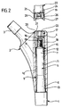
- the prosthesis socket shown in the drawing is essentially composed of two parts, namely a stem 1 and an upper part 2, which has a side protruding connecting pin 3 for one in the Drawing not shown joint ball carries.
- the stem 1 has a cone-shaped extension on its top 5 with a first, conical section 6, whose diameter towards the free End of extension 5 decreases, with one at the conical section 6 adjoining cylindrical section 7 and with an external thread pin 8.
- the extension 5 is surrounded by a thin-walled Sleeve 9 with a circular cylindrical outer surface 10 and with a likewise circular cylindrical inner surface 11, which are each conical towards the ends of the sleeve 9 expanded and there conical contact surfaces 12 and 13 respectively trains.
- the lower conical contact surface 13 is there complementary to the conical section 6 of the extension 5, the upper conical contact surface 12, however, always moves away from the edge of the sleeve 9 more of the cylindrical section of the extension 5 and together with this forms a wedge-shaped Annular gap 14, which widens towards the edge of the sleeve.
- annular gap 14 is one of the cross-sectional shape of the annular gap 14 complementary clamping sleeve 15 inserted, the over the edge of the sleeve 9 from the annular gap 14 protrudes.
- This clamping nut 17 has a lower clamping range 18 on and an upper screw-in area 19, which by a circumferential ring notch 20 are separated from each other.
- the clamping area 18 and the screw-in area 19 only through a narrow material web 21 connected to each other so that in this area a predetermined breaking point is created.
- an inner polygon 22 in the clamping nut 17 incorporated, the inner surfaces of contact surfaces form for insertion and removal tools.
- the inner polygon 22 is so deep that it has the screw-in area 19 completely interspersed and partly in the clamping area 18 dips.
- the stem 1 with the extension 5 in the through hole 4 inserted into the space between Extension 5 and through hole 4 becomes the sleeve 9 introduced, although it is also possible in principle push the sleeve 9 onto the extension 5 from the start and only then the stem 1 in the through hole 4 to introduce.
- the clamping sleeve 15 is then inserted into the annular gap 14, and the lock nut 17 is on the male threaded pin 8 screwed on, the lower edge of the Clamp nut 17 on the upper edge of the clamping sleeve 15 and this when screwing it further into the annular gap 14 presses.
- the annular gap is created by this pressure 14 expanded, and this leads to one Jamming of the extension 5 relative to the sleeve 9 and on the other hand, an expansion of the sleeve 9, which is thereby jammed with respect to the through hole 4.
- extension 5 is strong in the Sleeve 9 drawn in, so that the conical section 6th the extension 5 strongly against the conical contact surface 12 of the sleeve 9 is pressed, which also thereby expanded and pressed against the through hole 4 becomes. Overall, this leads to double jamming for a secure axial fixing of the extension 5 in the through hole 4.
- the clamping nut 17 is with a defined torque turned in. This can be done, for example, by that a torque wrench known per se is used.
- a screwing tool 23 is particularly advantageous for screwing in the clamping nut 17 .
- This has an insertion mandrel 24, which is complementary to the inner polygon 22 is formed and its length selected only as large is that it dips into the screw-in area 19, not but extends into the clamping area 18. For example, this will thereby ensuring that the insertion tool 23 expanded in stages and with it trained step 25 at the top of the screwing area 19 sits on the clamping nut 17.
- the screwing tool 23 carries several at its end axially parallel holding fingers distributed over the circumference 26, the inward projections at their free end 27 have. If you insert the screwing tool 23 with the mandrel 24 to the clamping nut 17 that the insertion mandrel 24 into the polygon 22 of the insertion area 19 plunges, so the holding fingers 26 to the outside of the screw-in area 19 Projections 27 dip into the ring notch 20.
- the breaks Predetermined breaking point which is thereby from the remaining clamping nut 17 separate screw-in area 19 remains after the separation connected to the screwing tool 23 because the Holding fingers 26 with those engaging in the ring notch 20 Protrusions 27 hold this screw-in area 19. This ensures that the screw-in area 19 is not lost in the operating area after separation.
- the clamping nut 17 After connecting the two parts of the prosthesis socket in the manner described is the through hole 4 at the top by screwing it in Clamping area 18 of clamping nut 17 is flush, the clamping nut 17 thus has at the same time Function of a plug.
- FIG. 3 is a very Similar structure chosen, corresponding parts therefore bear the same reference numerals.
- the embodiment Figure 3 differs from that of the figures 1 and 2 only in that the sleeve 9 is missing and that instead the inner wall of the through hole 4 is not circular cylindrical but in the area of the extension 5 corresponding to the inner wall the sleeve 9 in the embodiment of Figures 1 and 2 is contoured.
- the inner wall of the through hole 4 thus has a through hole in which a conically narrowing from bottom to top Section 28, a circular cylindrical section 29 flared portion 30 and a cylindrical Section 31 with a larger outer diameter together connect.
- the conical section 28 lies facing the conical section 6 of the extension 5, the conical section 30 forms together with the cylindrical portion 7 of the extension 5 den Annular gap 14 from.
Landscapes
- Health & Medical Sciences (AREA)
- Orthopedic Medicine & Surgery (AREA)
- Transplantation (AREA)
- Heart & Thoracic Surgery (AREA)
- Cardiology (AREA)
- Oral & Maxillofacial Surgery (AREA)
- Engineering & Computer Science (AREA)
- Biomedical Technology (AREA)
- Vascular Medicine (AREA)
- Life Sciences & Earth Sciences (AREA)
- Animal Behavior & Ethology (AREA)
- General Health & Medical Sciences (AREA)
- Public Health (AREA)
- Veterinary Medicine (AREA)
- Physical Education & Sports Medicine (AREA)
- Prostheses (AREA)
Abstract
Description
- Figur 1:
- eine Teilseitenansicht eines teilweise aufgebrochen dargestellten Prothesenschaftes mit aufgesetztem Eindrehwerkzeug;
- Figur 2:
- eine Ansicht ähnlich Figur 1 nach dem Verspannen der Einzelteile des Prothesenschaftes und
- Figur 3:
- eine Ansicht ähnlich Figur 2 bei einem abgewandelten Ausführungsbeispiel eines Prothesenschaftes.
Claims (15)
- Modular aufgebauter Prothesenschaft mit konischen Verbindungsflächen zur Festlegung benachbarter Teile des Prothesenschaftes aneinander, dadurch gekennzeichnet, daß ein erstes Teil (1) des Prothesenschaftes eine zapfenförmige Verlängerung (5) trägt, daß in einem benachbarten zweiten Teil (2) des Prothesenschaftes eine Durchgangsbohrung (4) zur Aufnahme der Verlängerung (5) vorgesehen ist, daß zwischen der Verlängerung (5) einerseits und der Innenwand (12; 30) der Durchgangsbohrung (4) andererseits ein sich in Richtung auf das erste Teil (1) keilförmig verengender Ringspalt (14) angeordnet ist, in den eine komplementär ausgebildete Klemmhülse (15) eintaucht, und daß an der Verlängerung (5) ein in Richtung auf das erste Teil (1) bewegbares Spannelement (17) gehalten ist, welches an der Klemmhülse (15) anliegt und diese im gespannten Zustand in den Ringspalt (14) eindrückt.
- Prothesenschaft nach Anspruch 1, dadurch gekennzeichnet, daß die zapfenförmige Verlängerung (5) im Bereich des Ringspaltes (14) kreiszylindrisch ausgebildet ist.
- Prothesenschaft nach einem der Ansprüche 1 oder 2, dadurch gekennzeichnet, daß die zapfenförmige Verlängerung (5) auf ihrer dem ersten Teil (1) zugewandten Seite einen sich in Richtung zum Ringspalt (14) hin konisch verjüngenden Abschnitt (6) aufweist, der an einem komplementären, sich in Richtung zum ersten Teil (1) konisch erweiternden Abschnitt (13; 28) der Durchgangsbohrung (4) anliegt.
- Prothesenschaft nach einem der voranstehenden Ansprüche, dadurch gekennzeichnet, daß die Innenwand (11, 12, 13) der Durchgangsbohrung (4) im Bereich der zapfenförmigen Verlängerung (5) von einer diese umgebenden, an der Außenseite (10) kreiszylindrischen Hülse (9) gebildet wird, die in die ebenfalls kreiszylindrische Durchgangsbohrung (4) eintaucht.
- Prothesenschaft nach Anspruch 4, dadurch gekennzeichnet, daß die Hülse (9) zumindest im Bereich des Ringspaltes (14) vom Rand ausgehende achsparallele Einschnitte aufweist.
- Prothesenschaft nach einem der voranstehenden Ansprüche, dadurch gekennzeichnet, daß das Spannelement eine Spannmutter (17) mit Innengewinde (16) ist, die auf einen Gewindezapfen (8) am Ende der Verlängerung (5) aufgeschraubt ist.
- Prothesenschaft nach Anspruch 6, dadurch gekennzeichnet, daß die Spannmutter (17) an ihrem dem Ringspalt (14) abgewandten Ende einen Eindrehabschnitt (19) mit Anlageflächen (22) für ein Eindrehwerkzeug (23) trägt, der über eine Sollbruchstelle (21) mit dem übrigen Teil der Spannmutter (17) verbunden ist.
- Prothesenschaft nach Anspruch 7, dadurch gekennzeichnet, daß die Anlageflächen durch einen Innenmehrkant (22) gebildet werden.
- Prothesenschaft nach Anspruch 7 oder 8, dadurch gekennzeichnet, daß die Sollbruchstelle (21) in Höhe des Endes der Durchgangsbohrung (4) angeordnet ist.
- Prothesenschaft nach einem der Ansprüche 7 bis 9, dadurch gekennzeichnet, daß in der Spannmutter (17) ein Anlageflächen für ein Ausdrehwerkzeug aufweisender Innenmehrkant (22) angeordnet ist, der nach Entfernung des Eindrehabschnittes (19) zugänglich ist.
- Prothesenschaft nach einem der Ansprüche 8 und 10, dadurch gekennzeichnet, daß der Innenmehrkant (22) für das Ausdrehwerkzeug durch eine Verlängerung des Innenmehrkants (22) im Eindrehabschnitt (19) gebildet wird.
- Prothesenschaft nach einem der Ansprüche 7 bis 11, dadurch gekennzeichnet, daß zwischen dem Eindrehabschnitt (19) und dem übrigen Teil (18) der Spannmutter (17) eine kerbenförmige Aufnahme (20) für den Eindrehabschnitt (19) zwischen sich aufnehmende Halteelemente (26) eines Eindrehwerkzeuges (23) angeordnet sind.
- Eindrehwerkzeug für eine Spannmutter (17) nach einem der Ansprüche 7 bis 12, dadurch gekennzeichnet, daß es einen Anschlag (25) aufweist, der die Eintauchtiefe von an den Anlageflächen (22) der Spannmutter (17) anliegenden Mitnahmeflächen (24) auf den Eindrehabschnitt (19) begrenzt.
- Eindrehwerkzeug nach Anspruch 13, dadurch gekennzeichnet, daß es an seinem Ende fingerförmige Halteelemente (26) trägt, die den Eindrehabschnitt (19) der Spannmutter (17) zwischen sich festhalten.
- Eindrehwerkzeug nach Anspruch 14, dadurch gekennzeichnet, daß die fingerförmigen Halteelemente (26) an ihren freien Enden Vorsprünge (27) tragen, die den Eindrehabschnitt (19) der Spannmutter (17) umgreifen.
Applications Claiming Priority (3)
| Application Number | Priority Date | Filing Date | Title |
|---|---|---|---|
| DE29910113U DE29910113U1 (de) | 1999-06-10 | 1999-06-10 | Prothesenschaft |
| DE19926391 | 1999-06-10 | ||
| DE19926391A DE19926391C1 (de) | 1999-06-10 | 1999-06-10 | Prothesenschaft |
Publications (3)
| Publication Number | Publication Date |
|---|---|
| EP1059070A2 true EP1059070A2 (de) | 2000-12-13 |
| EP1059070A3 EP1059070A3 (de) | 2002-05-22 |
| EP1059070B1 EP1059070B1 (de) | 2005-04-06 |
Family
ID=26053715
Family Applications (1)
| Application Number | Title | Priority Date | Filing Date |
|---|---|---|---|
| EP00111871A Expired - Lifetime EP1059070B1 (de) | 1999-06-10 | 2000-06-09 | Prothesenschaft |
Country Status (2)
| Country | Link |
|---|---|
| EP (1) | EP1059070B1 (de) |
| DE (2) | DE29910113U1 (de) |
Cited By (6)
| Publication number | Priority date | Publication date | Assignee | Title |
|---|---|---|---|---|
| FR2832624A1 (fr) * | 2001-11-23 | 2003-05-30 | Science Medecine Sa | Tige femorale pour prothese de hanche |
| EP1356795A1 (de) * | 2002-04-23 | 2003-10-29 | ESKA Implants GmbH & Co. | Set zur Erstellung eines Armierungsimplantates |
| EP1449500A3 (de) * | 2003-02-18 | 2004-10-20 | Zimmer Technology, Inc. | Modulares Knochenimplantat, Werkzeug und Verfahren |
| EP1493407A3 (de) * | 2003-07-03 | 2005-04-13 | Centerpulse Orthopedics Inc. | Modulare Hüftprothese |
| US7799086B2 (en) | 2002-04-25 | 2010-09-21 | Zimmer Technology, Inc. | Modular bone implant, tools, and method |
| US8048163B2 (en) | 2002-02-20 | 2011-11-01 | Zimmer, Inc. | Knee arthroplasty prosthesis |
Families Citing this family (6)
| Publication number | Priority date | Publication date | Assignee | Title |
|---|---|---|---|---|
| DE29910113U1 (de) * | 1999-06-10 | 1999-07-29 | Aesculap AG & Co. KG, 78532 Tuttlingen | Prothesenschaft |
| DE10119079C1 (de) * | 2001-04-19 | 2002-12-19 | Aesculap Ag & Co Kg | Modular aufgebaute Knochenraspel oder modular aufgebautes Schaftimplantat |
| US20040102852A1 (en) | 2002-11-22 | 2004-05-27 | Johnson Erin M. | Modular knee prosthesis |
| DE102005052699B3 (de) * | 2005-10-31 | 2007-02-22 | Aesculap Ag & Co. Kg | Implantat und Spannglied für ein Implantat |
| EP1787603A1 (de) | 2005-11-18 | 2007-05-23 | Zimmer GmbH | Basisplattform für ein künstliches Gelenk |
| DE102018105682A1 (de) | 2018-03-12 | 2019-09-12 | Aesculap Ag | Medizinische Mutter und Implantat |
Family Cites Families (22)
| Publication number | Priority date | Publication date | Assignee | Title |
|---|---|---|---|---|
| US2679245A (en) * | 1950-03-20 | 1954-05-25 | Timmermans Frans Donatus | Prosthesis for femoral heads |
| CH668703A5 (de) * | 1985-04-15 | 1989-01-31 | Sulzer Ag | Verbindung zweier implantat-teile. |
| DE8611697U1 (de) * | 1986-04-25 | 1986-06-19 | Mecron Medizinische Produkte Gmbh, 1000 Berlin | Bausatz für eine Schaftprothese |
| GB2223172A (en) * | 1988-07-05 | 1990-04-04 | L C Seventeen Limited | Shoulder joint structure |
| GB9000124D0 (en) * | 1990-01-04 | 1990-03-07 | Howmedica | Prosthetic bearing assembly |
| GB9122936D0 (en) * | 1991-10-30 | 1991-12-18 | Depuy Int Ltd | Assembly of components of an osteoprosthesis |
| FR2689001B1 (fr) * | 1992-03-24 | 1994-05-27 | Andre Rambert | Tige femorale vissee pour prothese de hanche. |
| DE4320086C3 (de) * | 1993-06-17 | 2002-05-16 | Peter Brehm | Modularer Schaft für ein Revisionshüftprothesensystem |
| IT1262759B (it) * | 1993-07-16 | 1996-07-04 | Mec Hint S R L | Perfezionamento al blocco tra i componenti di una protesi pluricomposta per l'impiego in traumatologia ortopedia e veterinaria |
| ATE174204T1 (de) * | 1993-10-21 | 1998-12-15 | Sulzer Orthopaedie Ag | Bausatz für eine modulare femurkopfprothese, insbesondere eine reoperationsprothese, und femurkopfprothese aus einem derartigen bausatz |
| IT1271759B (it) * | 1994-03-17 | 1997-06-09 | Cremascoli Srl G | Protesi femorale particolarmente studiata per la revisione di impianti protesici che hanno avuto esito negativo |
| US6478795B1 (en) * | 1994-08-29 | 2002-11-12 | Sofamor S.N.C. | Torque limiting clamping plug for osteosynthesis instrumentation |
| DE4442205A1 (de) * | 1994-11-19 | 1996-05-23 | Artos Med Produkte | Modulare Hüftgelenkprothese |
| DE4442204A1 (de) * | 1994-11-19 | 1996-05-23 | Artos Med Produkte | Modulare Gelenkprothese |
| FR2730628B1 (fr) * | 1995-01-27 | 1997-09-12 | Amp Dev | Prothese femorale modulaire a geometrie variable, notamment de reconstruction |
| DE29506036U1 (de) * | 1995-04-07 | 1995-06-01 | Brehm, Peter, 91085 Weisendorf | Modulares Femurprothesensystem mit einem Schaft bzw. Prothesennagel, auf welchen verschiedene Module aufsetzbar sind |
| DK0792628T3 (da) * | 1996-02-29 | 2002-08-26 | Werner Scholz | Endoprotese til et kunstigt hofteled |
| ATE230247T1 (de) * | 1997-07-04 | 2003-01-15 | Sulzer Orthopaedie Ag | Instrument zum einbringen eines einsatzes eines implantats in die zugehörige schale |
| US6308598B1 (en) * | 1998-11-23 | 2001-10-30 | O'neil Michael J. | Modular torque-limiting driver system for medical applications |
| US6264699B1 (en) * | 1998-11-23 | 2001-07-24 | Depuy Orthopaedics, Inc. | Modular stem and sleeve prosthesis |
| DE29910113U1 (de) * | 1999-06-10 | 1999-07-29 | Aesculap AG & Co. KG, 78532 Tuttlingen | Prothesenschaft |
| DE29918669U1 (de) * | 1999-10-22 | 1999-12-30 | KERAMED Medizintechnik GmbH, 07646 Mörsdorf | Schulter-Endoprothese |
-
1999
- 1999-06-10 DE DE29910113U patent/DE29910113U1/de not_active Expired - Lifetime
- 1999-06-10 DE DE19926391A patent/DE19926391C1/de not_active Expired - Fee Related
-
2000
- 2000-06-09 EP EP00111871A patent/EP1059070B1/de not_active Expired - Lifetime
Non-Patent Citations (1)
| Title |
|---|
| None |
Cited By (9)
| Publication number | Priority date | Publication date | Assignee | Title |
|---|---|---|---|---|
| FR2832624A1 (fr) * | 2001-11-23 | 2003-05-30 | Science Medecine Sa | Tige femorale pour prothese de hanche |
| US8048163B2 (en) | 2002-02-20 | 2011-11-01 | Zimmer, Inc. | Knee arthroplasty prosthesis |
| US9072605B2 (en) | 2002-02-20 | 2015-07-07 | Zimmer, Inc. | Knee arthroplasty prosthesis |
| EP1356795A1 (de) * | 2002-04-23 | 2003-10-29 | ESKA Implants GmbH & Co. | Set zur Erstellung eines Armierungsimplantates |
| US7182786B2 (en) | 2002-04-25 | 2007-02-27 | Zimmer Technology, Inc. | Modular bone implant, tool, and method |
| US7799086B2 (en) | 2002-04-25 | 2010-09-21 | Zimmer Technology, Inc. | Modular bone implant, tools, and method |
| EP1449500A3 (de) * | 2003-02-18 | 2004-10-20 | Zimmer Technology, Inc. | Modulares Knochenimplantat, Werkzeug und Verfahren |
| EP1493407A3 (de) * | 2003-07-03 | 2005-04-13 | Centerpulse Orthopedics Inc. | Modulare Hüftprothese |
| AU2004203031B2 (en) * | 2003-07-03 | 2009-07-23 | Zimmer, Inc. | Modular hip prosthesis |
Also Published As
| Publication number | Publication date |
|---|---|
| DE19926391C1 (de) | 2001-02-01 |
| DE29910113U1 (de) | 1999-07-29 |
| EP1059070A3 (de) | 2002-05-22 |
| EP1059070B1 (de) | 2005-04-06 |
Similar Documents
| Publication | Publication Date | Title |
|---|---|---|
| EP0243298B1 (de) | Bausatz für eine Schaftprothese | |
| DE4320086C2 (de) | Modularer Schaft für ein Revisionshüftprothesensystem | |
| DE10065398C2 (de) | Längenverstellbarer Platzhalter zum Einsetzen zwischen zwei Wirbelkörper | |
| DE19841252B4 (de) | Einsetzinstrument für eine Knochenschraube | |
| DE102007042959B4 (de) | Chirurgische Halteschraube | |
| DE102005021879B4 (de) | Orthopädisches Verankerungselement und Osteosynthesevorrichtung | |
| EP0528262B1 (de) | Mechanische Spannvorrichtung | |
| EP0792628B1 (de) | Endoprothese für ein künstliches Hüftgelenk | |
| DE29819914U1 (de) | Endoskopisches Einsetzinstrumentarium | |
| EP0801544A1 (de) | Verbindungsanordnung zwischen einem implantat und einem abutment | |
| DE29701099U1 (de) | Stiftförmiges Halteelement für ein orthopädisches Haltesystem | |
| EP0954247A1 (de) | Vorrichtung zur verbindung eines langsträgers mit einer pedikelschraube | |
| EP2976031A1 (de) | Wirbelsäulenstabilisierungssystem und chirurgisches befestigungselement für ein wirbelsäulenstabilisierungssystem | |
| WO1996015737A1 (de) | Gelenkprothese | |
| EP1059070B1 (de) | Prothesenschaft | |
| EP1651133B1 (de) | Implantatteil für ein zahnimplantat | |
| WO1993010930A1 (de) | Werkzeugkupplung, die eine radial elastisch aufspreizbare anschlusshülse und einen schaft mit einem spannkörper aufweist | |
| DE29805443U1 (de) | Orthopädisches Kompressionsschrauben-Baukastensystem | |
| EP2346445B1 (de) | Endoprothese mit einer steckverbindung und verbesserter drehsicherung | |
| DE202005007495U1 (de) | Orthopädisches Verankerungselement und Osteosynthesevorrichtung | |
| EP2822507B1 (de) | Prothesenteil | |
| EP1922032A2 (de) | Endoprothesensatz mit distraktionsinstrument | |
| DE3826342A1 (de) | Verbindung zwischen einem betonstahl und einem anzuschliessenden element | |
| EP1098612A2 (de) | Gelenkprothesen-system | |
| DE20106723U1 (de) | Modular aufgebaute Knochenraspel oder Modular aufgebautes Schaftimplantat |
Legal Events
| Date | Code | Title | Description |
|---|---|---|---|
| PUAI | Public reference made under article 153(3) epc to a published international application that has entered the european phase |
Free format text: ORIGINAL CODE: 0009012 |
|
| AK | Designated contracting states |
Kind code of ref document: A2 Designated state(s): AT BE CH CY DE DK ES FI FR GB GR IE IT LI LU MC NL PT SE |
|
| AX | Request for extension of the european patent |
Free format text: AL;LT;LV;MK;RO;SI |
|
| PUAL | Search report despatched |
Free format text: ORIGINAL CODE: 0009013 |
|
| AX | Request for extension of the european patent |
Free format text: AL;LT;LV;MK;RO;SI |
|
| 17P | Request for examination filed |
Effective date: 20021113 |
|
| AKX | Designation fees paid |
Designated state(s): CH ES FR GB IT LI |
|
| REG | Reference to a national code |
Ref country code: DE Ref legal event code: 8566 |
|
| 17Q | First examination report despatched |
Effective date: 20040607 |
|
| GRAP | Despatch of communication of intention to grant a patent |
Free format text: ORIGINAL CODE: EPIDOSNIGR1 |
|
| GRAS | Grant fee paid |
Free format text: ORIGINAL CODE: EPIDOSNIGR3 |
|
| GRAA | (expected) grant |
Free format text: ORIGINAL CODE: 0009210 |
|
| AK | Designated contracting states |
Kind code of ref document: B1 Designated state(s): CH ES FR GB IT LI |
|
| PG25 | Lapsed in a contracting state [announced via postgrant information from national office to epo] |
Ref country code: GB Free format text: LAPSE BECAUSE OF FAILURE TO SUBMIT A TRANSLATION OF THE DESCRIPTION OR TO PAY THE FEE WITHIN THE PRESCRIBED TIME-LIMIT Effective date: 20050406 |
|
| REG | Reference to a national code |
Ref country code: GB Ref legal event code: FG4D Free format text: NOT ENGLISH |
|
| REG | Reference to a national code |
Ref country code: CH Ref legal event code: EP Ref country code: CH Ref legal event code: NV Representative=s name: ISLER & PEDRAZZINI AG |
|
| REG | Reference to a national code |
Ref country code: IE Ref legal event code: FG4D Free format text: LANGUAGE OF EP DOCUMENT: GERMAN |
|
| PG25 | Lapsed in a contracting state [announced via postgrant information from national office to epo] |
Ref country code: ES Free format text: LAPSE BECAUSE OF FAILURE TO SUBMIT A TRANSLATION OF THE DESCRIPTION OR TO PAY THE FEE WITHIN THE PRESCRIBED TIME-LIMIT Effective date: 20050717 |
|
| GBV | Gb: ep patent (uk) treated as always having been void in accordance with gb section 77(7)/1977 [no translation filed] |
Effective date: 20050406 |
|
| PLBE | No opposition filed within time limit |
Free format text: ORIGINAL CODE: 0009261 |
|
| STAA | Information on the status of an ep patent application or granted ep patent |
Free format text: STATUS: NO OPPOSITION FILED WITHIN TIME LIMIT |
|
| ET | Fr: translation filed | ||
| 26N | No opposition filed |
Effective date: 20060110 |
|
| REG | Reference to a national code |
Ref country code: CH Ref legal event code: PCAR Free format text: ISLER & PEDRAZZINI AG;POSTFACH 1772;8027 ZUERICH (CH) |
|
| PGFP | Annual fee paid to national office [announced via postgrant information from national office to epo] |
Ref country code: IT Payment date: 20090609 Year of fee payment: 10 Ref country code: FR Payment date: 20090407 Year of fee payment: 10 |
|
| PGFP | Annual fee paid to national office [announced via postgrant information from national office to epo] |
Ref country code: CH Payment date: 20090708 Year of fee payment: 10 |
|
| REG | Reference to a national code |
Ref country code: CH Ref legal event code: PL |
|
| REG | Reference to a national code |
Ref country code: FR Ref legal event code: ST Effective date: 20110228 |
|
| PG25 | Lapsed in a contracting state [announced via postgrant information from national office to epo] |
Ref country code: IT Free format text: LAPSE BECAUSE OF NON-PAYMENT OF DUE FEES Effective date: 20100609 |
|
| PG25 | Lapsed in a contracting state [announced via postgrant information from national office to epo] |
Ref country code: CH Free format text: LAPSE BECAUSE OF NON-PAYMENT OF DUE FEES Effective date: 20100630 Ref country code: LI Free format text: LAPSE BECAUSE OF NON-PAYMENT OF DUE FEES Effective date: 20100630 |
|
| PG25 | Lapsed in a contracting state [announced via postgrant information from national office to epo] |
Ref country code: FR Free format text: LAPSE BECAUSE OF NON-PAYMENT OF DUE FEES Effective date: 20100630 |