EP1058322A1 - Mécanisme de déplacement utilisant un organe d'actionnement piezo-électrique - Google Patents
Mécanisme de déplacement utilisant un organe d'actionnement piezo-électrique Download PDFInfo
- Publication number
- EP1058322A1 EP1058322A1 EP00401352A EP00401352A EP1058322A1 EP 1058322 A1 EP1058322 A1 EP 1058322A1 EP 00401352 A EP00401352 A EP 00401352A EP 00401352 A EP00401352 A EP 00401352A EP 1058322 A1 EP1058322 A1 EP 1058322A1
- Authority
- EP
- European Patent Office
- Prior art keywords
- piezoelectric element
- moving part
- piezoelectric
- deformation
- transmission rod
- Prior art date
- Legal status (The legal status is an assumption and is not a legal conclusion. Google has not performed a legal analysis and makes no representation as to the accuracy of the status listed.)
- Granted
Links
- 230000010355 oscillation Effects 0.000 claims abstract description 3
- 230000005540 biological transmission Effects 0.000 claims description 52
- 230000033001 locomotion Effects 0.000 claims description 29
- 230000003534 oscillatory effect Effects 0.000 claims description 15
- 238000005452 bending Methods 0.000 claims description 13
- 238000006073 displacement reaction Methods 0.000 claims description 4
- 230000001939 inductive effect Effects 0.000 claims 1
- 239000000463 material Substances 0.000 description 6
- 235000012431 wafers Nutrition 0.000 description 4
- 230000000903 blocking effect Effects 0.000 description 3
- 230000000737 periodic effect Effects 0.000 description 3
- 238000004026 adhesive bonding Methods 0.000 description 2
- 229910010293 ceramic material Inorganic materials 0.000 description 2
- 230000001105 regulatory effect Effects 0.000 description 2
- 230000001154 acute effect Effects 0.000 description 1
- 230000015572 biosynthetic process Effects 0.000 description 1
- 239000000919 ceramic Substances 0.000 description 1
- 230000008602 contraction Effects 0.000 description 1
- 230000001276 controlling effect Effects 0.000 description 1
- NKZSPGSOXYXWQA-UHFFFAOYSA-N dioxido(oxo)titanium;lead(2+) Chemical compound [Pb+2].[O-][Ti]([O-])=O NKZSPGSOXYXWQA-UHFFFAOYSA-N 0.000 description 1
- 230000005284 excitation Effects 0.000 description 1
- 239000000203 mixture Substances 0.000 description 1
- 239000000126 substance Substances 0.000 description 1
- 238000010408 sweeping Methods 0.000 description 1
Images


Classifications
-
- H—ELECTRICITY
- H02—GENERATION; CONVERSION OR DISTRIBUTION OF ELECTRIC POWER
- H02N—ELECTRIC MACHINES NOT OTHERWISE PROVIDED FOR
- H02N2/00—Electric machines in general using piezoelectric effect, electrostriction or magnetostriction
- H02N2/0005—Electric machines in general using piezoelectric effect, electrostriction or magnetostriction producing non-specific motion; Details common to machines covered by H02N2/02 - H02N2/16
- H02N2/001—Driving devices, e.g. vibrators
- H02N2/002—Driving devices, e.g. vibrators using only longitudinal or radial modes
-
- H—ELECTRICITY
- H02—GENERATION; CONVERSION OR DISTRIBUTION OF ELECTRIC POWER
- H02N—ELECTRIC MACHINES NOT OTHERWISE PROVIDED FOR
- H02N2/00—Electric machines in general using piezoelectric effect, electrostriction or magnetostriction
- H02N2/0005—Electric machines in general using piezoelectric effect, electrostriction or magnetostriction producing non-specific motion; Details common to machines covered by H02N2/02 - H02N2/16
- H02N2/001—Driving devices, e.g. vibrators
- H02N2/003—Driving devices, e.g. vibrators using longitudinal or radial modes combined with bending modes
-
- H—ELECTRICITY
- H02—GENERATION; CONVERSION OR DISTRIBUTION OF ELECTRIC POWER
- H02N—ELECTRIC MACHINES NOT OTHERWISE PROVIDED FOR
- H02N2/00—Electric machines in general using piezoelectric effect, electrostriction or magnetostriction
- H02N2/0005—Electric machines in general using piezoelectric effect, electrostriction or magnetostriction producing non-specific motion; Details common to machines covered by H02N2/02 - H02N2/16
- H02N2/005—Mechanical details, e.g. housings
- H02N2/0065—Friction interface
-
- H—ELECTRICITY
- H02—GENERATION; CONVERSION OR DISTRIBUTION OF ELECTRIC POWER
- H02N—ELECTRIC MACHINES NOT OTHERWISE PROVIDED FOR
- H02N2/00—Electric machines in general using piezoelectric effect, electrostriction or magnetostriction
- H02N2/02—Electric machines in general using piezoelectric effect, electrostriction or magnetostriction producing linear motion, e.g. actuators; Linear positioners ; Linear motors
- H02N2/026—Electric machines in general using piezoelectric effect, electrostriction or magnetostriction producing linear motion, e.g. actuators; Linear positioners ; Linear motors by pressing one or more vibrators against the driven body
-
- H—ELECTRICITY
- H01—ELECTRIC ELEMENTS
- H01H—ELECTRIC SWITCHES; RELAYS; SELECTORS; EMERGENCY PROTECTIVE DEVICES
- H01H57/00—Electrostrictive relays; Piezoelectric relays
Definitions
- the invention relates to an actuation device comprising at least one piezoelectric motor and a moving part under the action of said piezoelectric motor.
- the document EP-A-0 633 616 describes such a device in which the motor includes a piezoelectric element which has several electrodes on its area.
- this piezoelectric element On one side of this piezoelectric element is arranged a piece of movement transmission in contact with the moving part, and on the other side, a spring.
- This device also has a relatively large size for its application, especially for electrical relays.
- the invention therefore aims to remedy these drawbacks by providing a actuating device using a moving part moved by a motor piezoelectric which is smaller and simpler in its implementation work than those of the prior art.
- the invention aims to provide such actuator whose operation does not require the use an external mechanical force, such as that provided by a spring, to cause the moving part to move.
- the invention provides an actuating device comprising at less a piezoelectric motor and a moving part, wherein said motor piezoelectric is formed of at least one piezoelectric element associated with means for supplying electric current making it possible to induce oscillatory deformations of said piezoelectric element, and in which the part mobile comprises at least one micro rack intended to allow the transmission to the moving part of the driving force generated by the oscillatory deformations of the piezoelectric element.
- the micro rack has a surface on which, in part of the deformation cycle, the piezoelectric element exerts a force allowing the displacement of the moving part and a second surface along which, on a second part of the deformation cycle, the piezoelectric element exerts substantially no effort on the moving part.
- the micro rack is made up of a succession of dihedrons including the height is of the order of magnitude of the amplitude of the deformations oscillations of the piezoelectric element.
- a deformation transmission rod is associated with the piezoelectric element to come to engage and disengage from the micro rack when the piezoelectric element deforms in an oscillatory way.
- the piezoelectric element In a first embodiment of the piezoelectric element, it deformation essentially by elongation.
- a spring can then be associated with the transmission rod to facilitate the passage of the transmission rod from a dihedral to the adjacent dihedral during the moving part.
- the piezoelectric element In a second embodiment of the piezoelectric element, it deformation essentially by elongation and by bending.
- the device comprises a microphone rack and a piezoelectric motor, a return spring being associated with the movable element.
- the device comprises two microphones racks and two piezoelectric motors.
- the device further comprises means for locking in position the moving part.
- An actuating device comprises at least one piezoelectric motor 1 and a moving part 2 under the action of said piezoelectric motor 1.
- the piezoelectric motor 1 comprises at least one element 3, 4 formed in piezoelectric material associated with an electrical supply means 5 capable of excite at least one resonance mode of the piezoelectric element 3, 4 of so as to induce oscillatory deformations of it.
- the frequency of the current delivered can be between 10 and 200 kHz and the voltage between 30 and 500 V.
- the piezoelectric element 3, 4 is for example made of PZT type ceramic (lead titanate and zirconate) and in the form of a plate rectangular parallelepiped whose length is greater than the thickness, by example of the order of 10 times greater.
- the moving part 2 is intended to move under the action of the driving force generated by the oscillatory deformations of the piezoelectric element 3, 4.
- the transmission to the moving part 2 of the driving force generated by the oscillatory deformations of the piezoelectric element 3, 4 is performed at by means of at least one micro rack 6, 7 which is carried out, for example by engraving on the moving part 2.
- the geometry of the micro rack 6, 7 is such that it has a surface on which, in part of the deformation cycle, the piezoelectric element 3, 4 exerts a force allowing the moving part 2 to move and, a second surface along which on a second part of the cycle of deformation, the piezoelectric element 3, 4 exerts substantially no effort on the moving part 2.
- the moving part 2 is shaped rectangular parallelepiped and the micro rack 6, 7 is arranged in a axis of the moving part 2. The movement of the moving part 2 is then linear.
- the moving part 2 is not shaped rectangular parallelepiped and / or micro rack 6, 7 is not arranged along an axis of the moving part 2 so as to provide a device actuation whose movement of the moving part 2 is not linear.
- the moving part 2 is cylindrical in shape and the micro rack 6, 7 is arranged along its circumference so as to move the moving part 2 by rotation.
- the micro rack 6, 7 is arranged on the periphery of a movable part 2 of any shape along a propeller so as to move the moving part 2 simultaneously in rotation and in translation.
- the axis XX ' corresponds to the axis of movement of the moving part 2 and the axis YY 'is perpendicular, in the plane of the figures, to the axis XX'.
- These axes define for the moving part 2 the terms: upper end 8 (on the side X), lower end 9 (on the X 'side), right side 10 (on the Y side) and left side 14 (on the Y 'side).
- the movable part includes a micro rack 6 and is moved by a piezoelectric motor 1 while in the second embodiment shown in the Figure 2, the moving part includes two micro racks 6, 7 and is moved by two piezoelectric motors 1.
- the movable part 2 for example formed of ceramic material, is shaped rectangular parallelepiped. On the right side 10 of the moving part 2, a micro rack 6 has been engraved in the XX 'direction.
- a second micro rack 7 is formed on the left side 11 of the moving part 2.
- the two microphones racks 6, 7 are arranged symmetrically with respect to the center O moving part 2.
- the direction XX ' corresponds to the long length of the moving part 2.
- the movement of the moving part is then linear in the direction XX 'of propagation of the micro rack 6, 7.
- the micro racks 6, 7 are formed by a succession of dihedrons 12 having a wall 13 perpendicular to the direction XX '(direction YY') and a second wall 14 forming an acute angle ⁇ (direction ZZ '), for example of the order 45 °, with said first wall 13.
- the piezoelectric elements 3, 4 are arranged respectively opposite the micro rack 6, 7 according to the direction ZZ ', so as to be parallel to said second walls 14.
- An alternating current generator 5 adjustable in frequency and amplitude supplies the piezoelectric elements 3, 4 via two electrodes E1, E2 located on either side of each of the piezoelectric elements 3, 4.
- the two electrodes E1, E2 are arranged with on either side of the smallest dimension of the piezoelectric element 3, 4.
- a transmission rod 16 of the oscillatory deformation of the piezoelectric element On the end 14 of the piezoelectric elements 3, 4 which are located opposite of the movable part 2, is arranged, for example by gluing or the like, a transmission rod 16 of the oscillatory deformation of the piezoelectric element.
- the transmission rod 16 is shaped, in particular by its size, so as to be able to engage and disengage from the micro rack 6, 7 under the action of the deformations of the piezoelectric element 3, 4.
- the piezoelectric motors 1 include such a transmission rod 16, one can consider that it is directly the piezoelectric element 3, 4 which comes to engage in the micro rack 3, 4.
- the piezoelectric elements 3, 4 are fixed by their end 17, opposite to the transmission rod 16 to a support (not shown) so as to be fixed by relative to the moving part 2.
- the relative arrangement of a piezoelectric element 3, 4 with a microphone rack 6, 7 is such that the oscillatory deformations of the piezoelectric element 3, 4 induce part of the deformation cycle of the transmission rod 16 in the micro rack 6, 7 and on the other part of the cycle his disengagement.
- the micro rack 6, 7 is formed by a succession of dihedrons 12 which have a height (i.e. the distance AB in the direction YY ' shown in Figures 3 to 6) of the order of magnitude of the amplitude of oscillatory deformations of the piezoelectric element 3, 4.
- the height of the dihedrons is between 0.5 and 5 ⁇ m.
- a locking device 18 in position can be provided for retaining the part mobile 2 when the transmission rod 16 is disengaged from the microphone rack 6, 7 and in particular when the piezoelectric element 3, 4 is not supplied with electric current.
- the locking device 18 is formed of a flexible blade 19 whose one end engages in successive dihedrons 12 when moving the movable part 2. This blade 19 being rigid enough to maintain in position the moving part 2 when the transmission rod 16 is disengaged.
- the locking device 18 can also be formed of plates rubbing the moving part 2 if we can accept a small loss of energy by friction.
- the blade 19 is provided near a piezoelectric motor 1 without however interfere with the oscillatory deformations of the piezoelectric element 3, 4 and the transmission rod 16 associated therewith.
- blade 19 is located opposite the dihedral 12 adjacent to that in which the rod transmission 16 is engaged.
- the blade 19 is rotatably mounted around of an axis 20 and is actuated, for example by an electromagnet 27 or by a additional piezoelectric motor, respectively in one position active or in a passive position.
- the blade 19 engages in the successive dihedrons 12 of so as to retain the moving part 2 in position when the transmission rod 16 is not engaged in a dihedral 12.
- the blade 19 In the passive position, the blade 19 is turned by an angle sufficient to be distant from the micro rack 16 and therefore not to interfere with the movement of the moving part 2.
- the blade 19 can be actuated by two stops limit switches provided on each of the upper ends 8 and bottom 9 of the moving part 2.
- the two stops and the blade 19 are located on a axis offset from the piezoelectric motor 1 so that these elements do not interfere with the piezoelectric motor 1 during movement of the moving part 2.
- the locking device 18 then passes from a active position to a passive position and vice versa at each limit switch of the transmission rod 16 in the micro rack 6.
- the operating principle of such a motor is then to supply the piezoelectric element 3 with electric current so as to move the moving part 2 in the X direction.
- the blade 19 is engaged (active position) in the micro rack 6 so as to retain the moving part 2, in particular in the event of a power cut.
- a spring 22 is associated on the one hand with the lower end 9 of the movable part 2 and on the other hand with a fixed support (not shown). When the moving part 2 moves in the X direction, the spring 22 gradually tends.
- the power supply of the piezoelectric element 3 is cut.
- the blocking device 18 is then actuated to a passive position so as to release the moving part 2.
- the return in the X 'direction of the moving part 2 is then ensured by force mechanics exerted by the spring 22 on the moving part 2.
- the locking device 18 is then actuated towards a position active.
- the piezoelectric element 3 can then be supplied again with electric current so as to ensure a new movement of the part mobile 2 in direction X.
- a two-way translation of the moving part 2 is thus obtained, in the direction X by electrically supplying the piezoelectric element 3, the blocking 18 being in the active position, and in the X 'direction by cutting the supply electric of the piezoelectric element 3, the blocking device 18 being in passive position.
- the tilting of the locking device 18 is carried out automatically each time end of travel of the moving part 2 in the X direction or in the X 'direction.
- the power supply to the piezoelectric element 3 is cut off after the locking device 18 has tilted.
- the end of the blade opposite the micro rack 6 is fixed to a support, for example the same support as that to which the piezoelectric element 3 is fixed.
- the locking device 18 is always in the active position.
- the two-way translation is obtained by successively supplying the first piezoelectric element 3 to obtain the translation along X then the second 4 to obtain the translation in the X 'direction.
- the two micro racks 6, 7, in particular by being symmetrical by relative to the center O of the moving part 2, have profiles capable of allow the moving part 2 to move each in a different direction.
- point A corresponding to a vertex common to two adjacent 12 dihedrons and point B corresponding to a base common to two adjacent 12 dihedrons.
- the deformation of the piezoelectric element 3, 4 is essentially an elongation deformation.
- the rod transmission is then animated by a periodic linear movement.
- the material forming the piezoelectric element 3, 4 is chosen for undergo oscillatory deformations essentially by elongation at the excitation frequency used. Such materials are available commercially depending on the desired characteristics.
- the element piezoelectric 3, 4 lengthens.
- the end of the transmission rod 16 passes then from the vicinity of point A to the vicinity of point B.
- the passage from one dihedral 12 to the other at the level of the point A can be facilitated by the action of a spring 23 acting on the element piezoelectric 3, 4 or directly on the transmission rod 16, in the direction reverse of the movement of the moving part 2, for example perpendicularly to the axis ZZ '.
- the succession of elongation and contraction cycles of the piezoelectric element 3, 4 therefore causes a continuous linear movement of the part mobile 2 in direction X, respectively X '.
- the speed of movement of the moving part 2 is then imposed by the frequency of oscillatory deformations of the piezoelectric element 3, 4.
- One way to overcome this constraint is, for example, to pulse the supply current of the piezoelectric element 3, 4 by means of a electronic control.
- the pulsed current then induces periods during which the piezoelectric element 3, 4 is supplied with current and therefore during which the part mobile 2 moves (active times), and periods when the current is zero and therefore where the moving part 2 does not move (dead time).
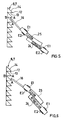
- the deformation of the piezoelectric element 3, 4 is a deformation by elongation and by bending.
- the rod transmission 16 is then animated by a periodic elliptical movement due to the combination of linear motion and induced sweeping motion respectively by the elongation and by the periodic bending of the piezoelectric element 3, 4.
- the piezoelectric element 3, 4 is formed by two piezoelectric plates 24, 25 joined to one another on part of their surface respective, for example by gluing.
- Each of the two plates 24, 25 includes two electrodes E1, E2 located on either side of their surface respective and a power supply means 5, for example different.
- the two plates 24, 25 are supplied with a given frequency current.
- the two means of power supply 5 then make it possible to supply two electrical signals of different voltage.
- the material of the first plate 24 is such that the frequency applied mainly excites its resonance mode of elongation deformation while the material of the second wafer 25 is excited mainly by bending at the frequency considered.
- These two materials are for example made of PZT with compositions chemical and / or different structural properties.
- the transmission rod 16 describes an ellipse whose period depends on the frequency applied to the two wafers.
- the speed of movement of the moving part 2 can be regulated by a command electronic power supply pulse frequency.
- the two plates 24, 25 are formed with the same ceramic material.
- the second wafer 25 is supplied with current at a first frequency mainly to excite its deformation resonance mode by bending and the first plate 24 is supplied with current to a second harmonic frequency of the first frequency to excite mainly its mode of resonance of strain by elongation.
- Synchronization between the elongation movement and the flexion movement is then carried out by means of an electronic control so that the transmission rod 16 periodically describes an ellipse.
- the element piezoelectric 3, 4 lengthens and bends in the direction of movement of the movable element 2.
- the end of the transmission rod 16 then passes from the near point A near point B.
- the element piezoelectric 3, 4 retracts and flexes in the opposite direction to the displacement of the movable element 2.
- the end of the transmission rod 16 then passes from the vicinity of point B to the vicinity of point A.
- the succession of deformation cycles of the piezoelectric element 3, 4 therefore causes a continuous linear movement of the moving part 2 in the direction X, respectively X '.
- the electronic control associated with the supply means 5 is suitable on the one hand for regulating the speed of movement and secondly to synchronize the elongation movement of the wafer 24 and that of bending of the plate 25.
- the electronic control will pulse the current of the supply means 5 so as to synchronize the two deformations at suitable times to cause the displacement of the moving part 2.
- an actuating device allows, thanks to the bending of the piezoelectric element 3, 4, the passage of the transmission rod 16 from a dihedral 12 to the adjacent dihedral without using a external mechanical force applied to the transmission rod 16.
Landscapes
- General Electrical Machinery Utilizing Piezoelectricity, Electrostriction Or Magnetostriction (AREA)
- Electrically Driven Valve-Operating Means (AREA)
- Apparatuses For Generation Of Mechanical Vibrations (AREA)
- Vehicle Body Suspensions (AREA)
Abstract
Description
- la figure 1 et une vue simplifiée et à plat d'un premier mode de réalisation d'un dispositif d'actionnement dont la pièce mobile comprend une micro crémaillère et est déplacée par un moteur piézo-électrique ;
- la figure 2 et une vue simplifiée et à plat d'un deuxième mode de réalisation d'un dispositif d'actionnement dont la pièce mobile comprend deux micro crémaillères et est déplacée par deux moteurs piézo-électriques ;
- les figures 3 et 4 illustrent respectivement l'étape d'engagement et de désengagement de la tige de transmission associée à une première variante d'un élément piézo-électrique se déformant essentiellement par élongation ;
- les figures 5 et 6 illustrent respectivement l'étape d'engagement et de désengagement de la tige de transmission associé à une deuxième variante d'un élément piézo-électrique se déformant par élongation et par flexion.
Un ressort 22 est associé d'une part à l'extrémité basse 9 de la pièce mobile 2 et d'autre part à un support fixe (non représenté). Lors du déplacement de la pièce mobile 2 dans le sens X, le ressort 22 se tend progressivement.
Claims (13)
- Dispositif d'actionnement comprenant au moins un moteur piézo-électrique (1) et une pièce mobile (2), dans lequel ledit moteur piézo-électrique (1) est formé d'au moins un élément piézo-électrique (3, 4) associé à des moyens d'alimentation (5) en courant électrique permettant d'induire des déformations oscillatoires dudit élément piézo-électrique (3, 4), caractérisé en ce que la pièce mobile (2) comprend au moins une micro crémaillère (6, 7) destinée à permettre la transmission à la pièce mobile (2) de la force motrice engendrée par les déformations oscillatoires de l'élément piézo-électrique (3, 4).
- Dispositif selon la revendication 1, caractérisé en ce que la micro crémaillère (6, 7) présente une surface sur laquelle, dans une partie du cycle de déformation, l'élément piézo-électrique (3, 4) exerce une force permettant le déplacement de la pièce mobile (2) et une deuxième surface le long de laquelle, sur une deuxième partie du cycle de déformation, l'élément piézo-électrique (3, 4) n'exerce sensiblement aucun effort sur la pièce mobile (1).
- Dispositif selon la revendication 2, caractérisé en ce que la micro crémaillère (6, 7) est formée d'une succession de dièdres (12) dont la hauteur est de l'ordre de grandeur de l'amplitude des déformations oscillatoires de l'élément piézo-électrique (3, 4).
- Dispositif selon l'une quelconque des revendications 1 à 3, caractérisé en ce qu'une commande électronique apte à commander la vitesse de déplacement de la pièce mobile (2) est associée aux moyens d'alimentation (5) en courant électrique.
- Dispositif selon l'une quelconques des revendications 1 à 4, caractérisé en ce qu'une tige de transmission (16) des déformations est associée à l'élément piézo-électrique (3, 4) pour venir s'engager et se désengager de la micro crémaillère (6, 7) lorsque l'élément piézo-électrique (3, 4) se déforme de façon oscillatoire.
- Dispositif selon l'une quelconques des revendications 1 à 5, caractérisé en ce que la déformation de l'élément piézo-électrique (3, 4) est une déformation essentiellement par élongation.
- Dispositif selon la revendication 6, caractérisé en ce qu'un ressort (23) est associé à la tige de transmission (16) pour faciliter le passage de la tige de transmission (16) d'un dièdre (12) au dièdre adjacent lors du déplacement de la pièce mobile (2).
- Dispositif selon l'une quelconques des revendications 1 à 5, caractérisé en ce que la déformation de l'élément piézo-électrique (3, 4) est une déformation essentiellement par élongation et par flexion.
- Dispositif selon la revendication 8, caractérisé en ce que la commande électronique associée aux moyens d'alimentation est apte à synchroniser la déformation par élongation et la déformation par flexion de l'élément piézo-électrique (3, 4).
- Dispositif selon l'une quelconque des revendications 1 à 9, caractérisé en ce qu'il comprend une micro crémaillère (6) et un moteur piézo-électrique (1).
- Dispositif selon la revendication 10, caractérisé en ce qu'un ressort de rappel (22) est associé à l'élément mobile (2).
- Dispositif selon l'une quelconque des revendications 1 à 9, caractérisé en ce qu'il comprend deux micro crémaillères (6, 7) et deux moteurs piézo-électriques (1).
- Dispositif selon l'une quelconque des revendications 1 à 12, caractérisé en ce qu'il comprend en outre des moyens de blocage (18) en position de la pièce mobile (2).
Applications Claiming Priority (2)
| Application Number | Priority Date | Filing Date | Title |
|---|---|---|---|
| FR9907101 | 1999-06-04 | ||
| FR9907101A FR2794581B1 (fr) | 1999-06-04 | 1999-06-04 | Dispositif d'actionnement comprenant au moins un moteur piezo-electrique et une piece mobile sous l'action dudit moteur piezo-electrique |
Publications (4)
| Publication Number | Publication Date |
|---|---|
| EP1058322A1 true EP1058322A1 (fr) | 2000-12-06 |
| EP1058322B1 EP1058322B1 (fr) | 2005-08-03 |
| EP1058322B8 EP1058322B8 (fr) | 2005-10-05 |
| EP1058322B9 EP1058322B9 (fr) | 2006-03-22 |
Family
ID=9546410
Family Applications (1)
| Application Number | Title | Priority Date | Filing Date |
|---|---|---|---|
| EP00401352A Expired - Lifetime EP1058322B9 (fr) | 1999-06-04 | 2000-05-17 | Mécanisme de déplacement utilisant un organe d'actionnement piezo-électrique |
Country Status (5)
| Country | Link |
|---|---|
| US (1) | US6429572B1 (fr) |
| EP (1) | EP1058322B9 (fr) |
| AT (1) | ATE301333T1 (fr) |
| DE (1) | DE60021659T2 (fr) |
| FR (1) | FR2794581B1 (fr) |
Cited By (1)
| Publication number | Priority date | Publication date | Assignee | Title |
|---|---|---|---|---|
| US8848859B2 (en) | 2009-01-13 | 2014-09-30 | Norbert Beyrard | X-ray or infrared imaging device comprising a dose limiter, with controlled translation speed |
Families Citing this family (2)
| Publication number | Priority date | Publication date | Assignee | Title |
|---|---|---|---|---|
| DE10146703A1 (de) * | 2001-09-21 | 2003-04-10 | Elliptec Resonant Actuator Ag | Piezomotor mit Führung |
| GB2560326A (en) * | 2017-03-07 | 2018-09-12 | Stratec Biomedical Ag | Piezo motor driven device |
Citations (3)
| Publication number | Priority date | Publication date | Assignee | Title |
|---|---|---|---|---|
| JPS62254669A (ja) * | 1986-04-28 | 1987-11-06 | Olympus Optical Co Ltd | 超音波モ−タ |
| US5049775A (en) * | 1988-09-30 | 1991-09-17 | Boston University | Integrated micromechanical piezoelectric motor |
| JPH04140074A (ja) * | 1990-10-01 | 1992-05-14 | Matsushita Electric Ind Co Ltd | 直進送り装置 |
Family Cites Families (4)
| Publication number | Priority date | Publication date | Assignee | Title |
|---|---|---|---|---|
| JPH04161077A (ja) * | 1990-10-19 | 1992-06-04 | Matsushita Electric Ind Co Ltd | 直進送り装置 |
| EP0633616B1 (fr) * | 1993-07-09 | 2002-01-30 | Nanomotion Ltd | Moteur céramique |
| US5616980A (en) * | 1993-07-09 | 1997-04-01 | Nanomotion Ltd. | Ceramic motor |
| US5682076A (en) * | 1993-08-03 | 1997-10-28 | Nanomotion Ltd. | Ceramic disc-drive actuator |
-
1999
- 1999-06-04 FR FR9907101A patent/FR2794581B1/fr not_active Expired - Fee Related
-
2000
- 2000-05-17 EP EP00401352A patent/EP1058322B9/fr not_active Expired - Lifetime
- 2000-05-17 AT AT00401352T patent/ATE301333T1/de not_active IP Right Cessation
- 2000-05-17 DE DE60021659T patent/DE60021659T2/de not_active Expired - Fee Related
- 2000-06-01 US US09/584,863 patent/US6429572B1/en not_active Expired - Fee Related
Patent Citations (3)
| Publication number | Priority date | Publication date | Assignee | Title |
|---|---|---|---|---|
| JPS62254669A (ja) * | 1986-04-28 | 1987-11-06 | Olympus Optical Co Ltd | 超音波モ−タ |
| US5049775A (en) * | 1988-09-30 | 1991-09-17 | Boston University | Integrated micromechanical piezoelectric motor |
| JPH04140074A (ja) * | 1990-10-01 | 1992-05-14 | Matsushita Electric Ind Co Ltd | 直進送り装置 |
Non-Patent Citations (2)
| Title |
|---|
| PATENT ABSTRACTS OF JAPAN vol. 012, no. 130 (E - 603) 21 April 1988 (1988-04-21) * |
| PATENT ABSTRACTS OF JAPAN vol. 016, no. 415 (E - 1257) 2 September 1992 (1992-09-02) * |
Cited By (1)
| Publication number | Priority date | Publication date | Assignee | Title |
|---|---|---|---|---|
| US8848859B2 (en) | 2009-01-13 | 2014-09-30 | Norbert Beyrard | X-ray or infrared imaging device comprising a dose limiter, with controlled translation speed |
Also Published As
| Publication number | Publication date |
|---|---|
| US6429572B1 (en) | 2002-08-06 |
| EP1058322B9 (fr) | 2006-03-22 |
| FR2794581A1 (fr) | 2000-12-08 |
| EP1058322B8 (fr) | 2005-10-05 |
| EP1058322B1 (fr) | 2005-08-03 |
| ATE301333T1 (de) | 2005-08-15 |
| FR2794581B1 (fr) | 2001-09-07 |
| DE60021659T2 (de) | 2006-05-18 |
| DE60021659D1 (de) | 2005-09-08 |
Similar Documents
| Publication | Publication Date | Title |
|---|---|---|
| EP3691110B1 (fr) | Mecanisme de deplacement nanometrique a vis | |
| FR2665033A1 (fr) | Dispositif de reglage pour micro-mouvements. | |
| EP2073228B1 (fr) | Commande compacte pour appareillage électrique moyennes et hautes tensions | |
| JP2011188739A (ja) | ウォーキングアクチュエータ | |
| EP0371896A1 (fr) | Dispositif de marquage par micro-percussion | |
| EP1058322B1 (fr) | Mécanisme de déplacement utilisant un organe d'actionnement piezo-électrique | |
| FR2772209A1 (fr) | Microactionneurs electrostatiques, microcatheters tridimensionnels actifs exploitant ceux-ci et procede de fabrication | |
| EP0537446A2 (fr) | Moteur piézo-électrique | |
| FR2750543A1 (fr) | Moteur piezoactif a base de modules statoriques independants | |
| FR2953661A1 (fr) | Dispositif generateur d'energie electrique | |
| EP0580049A1 (fr) | Moteur piézo-électrique | |
| EP1058323B1 (fr) | Contacteur-disjoncteur actionné par un moteur piezo-électrique | |
| FR2514928A1 (fr) | Dispositif de changement de mode de fonctionnement pour enregistreur sur bande magnetique | |
| CA2524171A1 (fr) | Moteur piezoelectrique permettant au moins deux degres de liberte, en rotation et en deplacement lineaire | |
| BE1004766A6 (fr) | Article mobile capable d'un mouvement de dilatation-contraction et de rotation. | |
| FR2883277A1 (fr) | Procede et dispositif pour deplacer un element a entrainer utilisant un element actionneur forme par gravure dans un materiau semi-conducteur | |
| FR2721675A1 (fr) | Dispositif d'entraînement en rotation utilisant plusieurs vérins de micro déplacements tangentiels. | |
| JP4685334B2 (ja) | 駆動装置およびチューブポンプ | |
| JP4561262B2 (ja) | アクチュエータ | |
| EP3836181A1 (fr) | Point de commande pour une installation de fermeture ou de protection solaire et installation de fermeture ou de protection solaire comprenant un tel point de commande | |
| WO1995002550A1 (fr) | Dispositif vibreur pour le transport ou le tri de pieces ou de materiaux pulverulents | |
| JP2004350413A (ja) | 超音波モータの駆動方法および駆動装置 | |
| EP3536493A1 (fr) | Presse électrique à moteur torque | |
| FR2907869A1 (fr) | Dispositif d'actionnement transformant un mouvement de va et vient en mouvement de translation ou de rotation | |
| JP2006067706A (ja) | アクチュエータ |
Legal Events
| Date | Code | Title | Description |
|---|---|---|---|
| PUAI | Public reference made under article 153(3) epc to a published international application that has entered the european phase |
Free format text: ORIGINAL CODE: 0009012 |
|
| AK | Designated contracting states |
Kind code of ref document: A1 Designated state(s): AT BE CH CY DE DK ES FI FR GB GR IE IT LI LU MC NL PT SE |
|
| AX | Request for extension of the european patent |
Free format text: AL;LT;LV;MK;RO;SI |
|
| 17P | Request for examination filed |
Effective date: 20001212 |
|
| AKX | Designation fees paid |
Free format text: AT BE CH CY DE DK ES FI FR GB GR IE IT LI LU MC NL PT SE |
|
| 17Q | First examination report despatched |
Effective date: 20040122 |
|
| GRAP | Despatch of communication of intention to grant a patent |
Free format text: ORIGINAL CODE: EPIDOSNIGR1 |
|
| RIN1 | Information on inventor provided before grant (corrected) |
Inventor name: BEYRARD, NORBERT |
|
| GRAS | Grant fee paid |
Free format text: ORIGINAL CODE: EPIDOSNIGR3 |
|
| GRAA | (expected) grant |
Free format text: ORIGINAL CODE: 0009210 |
|
| AK | Designated contracting states |
Kind code of ref document: B1 Designated state(s): AT BE CH CY DE DK ES FI FR GB GR IE IT LI LU MC NL PT SE |
|
| PG25 | Lapsed in a contracting state [announced via postgrant information from national office to epo] |
Ref country code: NL Free format text: LAPSE BECAUSE OF FAILURE TO SUBMIT A TRANSLATION OF THE DESCRIPTION OR TO PAY THE FEE WITHIN THE PRESCRIBED TIME-LIMIT Effective date: 20050803 Ref country code: AT Free format text: LAPSE BECAUSE OF FAILURE TO SUBMIT A TRANSLATION OF THE DESCRIPTION OR TO PAY THE FEE WITHIN THE PRESCRIBED TIME-LIMIT Effective date: 20050803 Ref country code: FI Free format text: LAPSE BECAUSE OF FAILURE TO SUBMIT A TRANSLATION OF THE DESCRIPTION OR TO PAY THE FEE WITHIN THE PRESCRIBED TIME-LIMIT Effective date: 20050803 Ref country code: IE Free format text: LAPSE BECAUSE OF FAILURE TO SUBMIT A TRANSLATION OF THE DESCRIPTION OR TO PAY THE FEE WITHIN THE PRESCRIBED TIME-LIMIT Effective date: 20050803 |
|
| REG | Reference to a national code |
Ref country code: GB Ref legal event code: FG4D Free format text: NOT ENGLISH |
|
| REG | Reference to a national code |
Ref country code: CH Ref legal event code: EP |
|
| REG | Reference to a national code |
Ref country code: IE Ref legal event code: FG4D Free format text: LANGUAGE OF EP DOCUMENT: FRENCH |
|
| REF | Corresponds to: |
Ref document number: 60021659 Country of ref document: DE Date of ref document: 20050908 Kind code of ref document: P |
|
| RAP2 | Party data changed (patent owner data changed or rights of a patent transferred) |
Owner name: NORBERT BEYRARD FRANCE (SARL) |
|
| PG25 | Lapsed in a contracting state [announced via postgrant information from national office to epo] |
Ref country code: DK Free format text: LAPSE BECAUSE OF FAILURE TO SUBMIT A TRANSLATION OF THE DESCRIPTION OR TO PAY THE FEE WITHIN THE PRESCRIBED TIME-LIMIT Effective date: 20051103 Ref country code: SE Free format text: LAPSE BECAUSE OF FAILURE TO SUBMIT A TRANSLATION OF THE DESCRIPTION OR TO PAY THE FEE WITHIN THE PRESCRIBED TIME-LIMIT Effective date: 20051103 Ref country code: GR Free format text: LAPSE BECAUSE OF FAILURE TO SUBMIT A TRANSLATION OF THE DESCRIPTION OR TO PAY THE FEE WITHIN THE PRESCRIBED TIME-LIMIT Effective date: 20051103 |
|
| PG25 | Lapsed in a contracting state [announced via postgrant information from national office to epo] |
Ref country code: ES Free format text: LAPSE BECAUSE OF FAILURE TO SUBMIT A TRANSLATION OF THE DESCRIPTION OR TO PAY THE FEE WITHIN THE PRESCRIBED TIME-LIMIT Effective date: 20051114 |
|
| REG | Reference to a national code |
Ref country code: CH Ref legal event code: NV Representative=s name: MOINAS & SAVOYE SA |
|
| GBT | Gb: translation of ep patent filed (gb section 77(6)(a)/1977) |
Effective date: 20051103 |
|
| NLT2 | Nl: modifications (of names), taken from the european patent patent bulletin |
Owner name: NORBERT BEYRARD FRANCE (SARL) Effective date: 20050921 |
|
| PG25 | Lapsed in a contracting state [announced via postgrant information from national office to epo] |
Ref country code: PT Free format text: LAPSE BECAUSE OF FAILURE TO SUBMIT A TRANSLATION OF THE DESCRIPTION OR TO PAY THE FEE WITHIN THE PRESCRIBED TIME-LIMIT Effective date: 20060103 |
|
| NLV1 | Nl: lapsed or annulled due to failure to fulfill the requirements of art. 29p and 29m of the patents act | ||
| REG | Reference to a national code |
Ref country code: IE Ref legal event code: FD4D |
|
| PG25 | Lapsed in a contracting state [announced via postgrant information from national office to epo] |
Ref country code: BE Free format text: LAPSE BECAUSE OF NON-PAYMENT OF DUE FEES Effective date: 20060531 Ref country code: MC Free format text: LAPSE BECAUSE OF NON-PAYMENT OF DUE FEES Effective date: 20060531 |
|
| PLBE | No opposition filed within time limit |
Free format text: ORIGINAL CODE: 0009261 |
|
| STAA | Information on the status of an ep patent application or granted ep patent |
Free format text: STATUS: NO OPPOSITION FILED WITHIN TIME LIMIT |
|
| 26N | No opposition filed |
Effective date: 20060504 |
|
| BERE | Be: lapsed |
Owner name: NORBERT BEYRARD FRANCE (SARL) Effective date: 20060531 |
|
| PG25 | Lapsed in a contracting state [announced via postgrant information from national office to epo] |
Ref country code: LU Free format text: LAPSE BECAUSE OF NON-PAYMENT OF DUE FEES Effective date: 20060517 |
|
| PG25 | Lapsed in a contracting state [announced via postgrant information from national office to epo] |
Ref country code: CY Free format text: LAPSE BECAUSE OF FAILURE TO SUBMIT A TRANSLATION OF THE DESCRIPTION OR TO PAY THE FEE WITHIN THE PRESCRIBED TIME-LIMIT Effective date: 20050803 |
|
| PGFP | Annual fee paid to national office [announced via postgrant information from national office to epo] |
Ref country code: IT Payment date: 20090424 Year of fee payment: 10 Ref country code: FR Payment date: 20090527 Year of fee payment: 10 Ref country code: DE Payment date: 20090603 Year of fee payment: 10 |
|
| PGFP | Annual fee paid to national office [announced via postgrant information from national office to epo] |
Ref country code: CH Payment date: 20090429 Year of fee payment: 10 |
|
| PGFP | Annual fee paid to national office [announced via postgrant information from national office to epo] |
Ref country code: GB Payment date: 20090427 Year of fee payment: 10 |
|
| REG | Reference to a national code |
Ref country code: CH Ref legal event code: PL |
|
| GBPC | Gb: european patent ceased through non-payment of renewal fee |
Effective date: 20100517 |
|
| REG | Reference to a national code |
Ref country code: FR Ref legal event code: ST Effective date: 20110131 |
|
| PG25 | Lapsed in a contracting state [announced via postgrant information from national office to epo] |
Ref country code: LI Free format text: LAPSE BECAUSE OF NON-PAYMENT OF DUE FEES Effective date: 20100531 Ref country code: CH Free format text: LAPSE BECAUSE OF NON-PAYMENT OF DUE FEES Effective date: 20100531 |
|
| PG25 | Lapsed in a contracting state [announced via postgrant information from national office to epo] |
Ref country code: IT Free format text: LAPSE BECAUSE OF NON-PAYMENT OF DUE FEES Effective date: 20100517 |
|
| PG25 | Lapsed in a contracting state [announced via postgrant information from national office to epo] |
Ref country code: DE Free format text: LAPSE BECAUSE OF NON-PAYMENT OF DUE FEES Effective date: 20101201 |
|
| PG25 | Lapsed in a contracting state [announced via postgrant information from national office to epo] |
Ref country code: FR Free format text: LAPSE BECAUSE OF NON-PAYMENT OF DUE FEES Effective date: 20100531 |
|
| PG25 | Lapsed in a contracting state [announced via postgrant information from national office to epo] |
Ref country code: GB Free format text: LAPSE BECAUSE OF NON-PAYMENT OF DUE FEES Effective date: 20100517 |