EP1057991A2 - Electronic fuel injection apparatus - Google Patents
Electronic fuel injection apparatus Download PDFInfo
- Publication number
- EP1057991A2 EP1057991A2 EP00111545A EP00111545A EP1057991A2 EP 1057991 A2 EP1057991 A2 EP 1057991A2 EP 00111545 A EP00111545 A EP 00111545A EP 00111545 A EP00111545 A EP 00111545A EP 1057991 A2 EP1057991 A2 EP 1057991A2
- Authority
- EP
- European Patent Office
- Prior art keywords
- fuel injection
- control circuit
- state
- command signal
- spill valve
- Prior art date
- Legal status (The legal status is an assumption and is not a legal conclusion. Google has not performed a legal analysis and makes no representation as to the accuracy of the status listed.)
- Withdrawn
Links
Images


Classifications
-
- F—MECHANICAL ENGINEERING; LIGHTING; HEATING; WEAPONS; BLASTING
- F02—COMBUSTION ENGINES; HOT-GAS OR COMBUSTION-PRODUCT ENGINE PLANTS
- F02D—CONTROLLING COMBUSTION ENGINES
- F02D41/00—Electrical control of supply of combustible mixture or its constituents
- F02D41/20—Output circuits, e.g. for controlling currents in command coils
-
- F—MECHANICAL ENGINEERING; LIGHTING; HEATING; WEAPONS; BLASTING
- F02—COMBUSTION ENGINES; HOT-GAS OR COMBUSTION-PRODUCT ENGINE PLANTS
- F02D—CONTROLLING COMBUSTION ENGINES
- F02D41/00—Electrical control of supply of combustible mixture or its constituents
- F02D41/22—Safety or indicating devices for abnormal conditions
- F02D41/221—Safety or indicating devices for abnormal conditions relating to the failure of actuators or electrically driven elements
-
- F—MECHANICAL ENGINEERING; LIGHTING; HEATING; WEAPONS; BLASTING
- F02—COMBUSTION ENGINES; HOT-GAS OR COMBUSTION-PRODUCT ENGINE PLANTS
- F02D—CONTROLLING COMBUSTION ENGINES
- F02D41/00—Electrical control of supply of combustible mixture or its constituents
- F02D41/30—Controlling fuel injection
- F02D41/38—Controlling fuel injection of the high pressure type
- F02D41/40—Controlling fuel injection of the high pressure type with means for controlling injection timing or duration
- F02D41/402—Multiple injections
- F02D41/403—Multiple injections with pilot injections
-
- F—MECHANICAL ENGINEERING; LIGHTING; HEATING; WEAPONS; BLASTING
- F02—COMBUSTION ENGINES; HOT-GAS OR COMBUSTION-PRODUCT ENGINE PLANTS
- F02D—CONTROLLING COMBUSTION ENGINES
- F02D41/00—Electrical control of supply of combustible mixture or its constituents
- F02D41/30—Controlling fuel injection
- F02D41/38—Controlling fuel injection of the high pressure type
- F02D41/40—Controlling fuel injection of the high pressure type with means for controlling injection timing or duration
- F02D41/406—Electrically controlling a diesel injection pump
- F02D41/408—Electrically controlling a diesel injection pump of the distributing type
-
- F—MECHANICAL ENGINEERING; LIGHTING; HEATING; WEAPONS; BLASTING
- F02—COMBUSTION ENGINES; HOT-GAS OR COMBUSTION-PRODUCT ENGINE PLANTS
- F02D—CONTROLLING COMBUSTION ENGINES
- F02D41/00—Electrical control of supply of combustible mixture or its constituents
- F02D41/20—Output circuits, e.g. for controlling currents in command coils
- F02D2041/202—Output circuits, e.g. for controlling currents in command coils characterised by the control of the circuit
- F02D2041/2055—Output circuits, e.g. for controlling currents in command coils characterised by the control of the circuit with means for determining actual opening or closing time
-
- F—MECHANICAL ENGINEERING; LIGHTING; HEATING; WEAPONS; BLASTING
- F02—COMBUSTION ENGINES; HOT-GAS OR COMBUSTION-PRODUCT ENGINE PLANTS
- F02D—CONTROLLING COMBUSTION ENGINES
- F02D41/00—Electrical control of supply of combustible mixture or its constituents
- F02D41/20—Output circuits, e.g. for controlling currents in command coils
- F02D2041/202—Output circuits, e.g. for controlling currents in command coils characterised by the control of the circuit
- F02D2041/2058—Output circuits, e.g. for controlling currents in command coils characterised by the control of the circuit using information of the actual current value
-
- Y—GENERAL TAGGING OF NEW TECHNOLOGICAL DEVELOPMENTS; GENERAL TAGGING OF CROSS-SECTIONAL TECHNOLOGIES SPANNING OVER SEVERAL SECTIONS OF THE IPC; TECHNICAL SUBJECTS COVERED BY FORMER USPC CROSS-REFERENCE ART COLLECTIONS [XRACs] AND DIGESTS
- Y02—TECHNOLOGIES OR APPLICATIONS FOR MITIGATION OR ADAPTATION AGAINST CLIMATE CHANGE
- Y02T—CLIMATE CHANGE MITIGATION TECHNOLOGIES RELATED TO TRANSPORTATION
- Y02T10/00—Road transport of goods or passengers
- Y02T10/10—Internal combustion engine [ICE] based vehicles
- Y02T10/40—Engine management systems
Definitions
- the present invention relates to an electronic fuel injection apparatus, and in particular to an electronic fuel injection apparatus which controls a distribution (VE)-type fuel injection pump for a diesel engine.
- VE distribution
- a control circuit of an electromagnetic spill valve (SPV) of a distribution-type fuel injection pump provided for adjusting a fuel injection quantity of a diesel engine in a conventional electronic fuel injection apparatus increases the fuel injection quantity to abnormally raise an engine revolution (RPM), resulting in a dangerous state when a fault occurs in the electromagnetic spill valve and the control circuit thereof.
- SPV electromagnetic spill valve
- RPM engine revolution
- the solenoid driving current of the electromagnetic spill valve supplied by the control circuit presents an abnormal state as in the Japanese Patent Publication Laid-open No.7-269404
- the abnormal state is detected by monitoring the voltage of a current supplying capacitor.
- the solenoid energizing time interval of the electromagnetic spill valve is elongated to advance the energizing time, thereby avoiding an engine stop state which may occur when a peak current cannot be supplied.
- It is accordingly an object of the present invention to provide an electronic fuel injection apparatus comprising a control circuit of an electromagnetic spill valve for adjusting a fuel injection quantity in a distribution-type fuel injection pump for a diesel engine, and a computing unit for providing a command signal to the control circuit, in which a dangerous state is prevented beforehand when faults occur not only in the control circuit of the electromagnetic spill valve but also in the electromagnetic spill valve per se.
- an electronic fuel injection apparatus comprises a control circuit having, on either an inside or outside of the control circuit of an electromagnetic spill valve, means for detecting a driving current which flows through a solenoid of the spill valve, and means for detecting a delay point at which the driving current detected crosses a threshold value, and a computing unit having means for determining a state where a delay time interval from a transit point of the command signal to the delay point is equal to or more than a predetermined value as a slightly abnormal state to invalidate the command signal for a pilot injection.
- the driving current which flows through the solenoid of the electromagnetic spill valve is detected, and the point (delay point) at which the driving current crosses (becomes equal to or more than, or equal to or less than) the threshold value is further detected. This may be executed on either the inside or outside of the control circuit.
- the computing unit determines whether or not the delay time interval from the transit point (switchover point of ON/OFF) of the command signal to the delay point is equal to or more than a predetermined time.
- the computing unit determines the state as a slightly abnormal state to invalidate the command signal for the pilot injection.
- the means for detecting the delay point may be provided in the computing unit on the outside of the control circuit.
- the state is determined as a seriously abnormal state to stop the engine at present.
- warning means when such an abnormal state is detected, a warning is given by using warning means.
- Fig. 1 shows an embodiment of an electronic fuel injection apparatus according to the present invention, which is schematically composed of an injection pump 1, an engine control computer (hereinafter abbreviated as ECC) 2, and an electromagnetic spill valve control circuit (EDU) 3.
- ECC engine control computer
- EDU electromagnetic spill valve control circuit
- the ECC 2 inputs an engine revolution signal from a revolution sensor 11 provided in the injection pump 1, a fuel temperature signal from a fuel temperature sensor 12, an accelerator opening signal, an intake pressure signal, a coolant temperature signal, a car speed signal, an intake temperature signal, and a crank angle signal respectively outputted from an accelerator opening sensor, a pressure sensor, a water temperature sensor, a speed sensor, an intake temperature sensor, and a crank position sensor (none of which are shown). Then, the ECC 2 performs a predetermined computation for providing a command signal CMD to the control circuit 3 of the electromagnetic spill valve and for providing a control signal to a timing control valve (hereinafter abbreviated as TCV) 24.
- TCV timing control valve
- control circuit 3 sends a driving signal to a solenoid 14 in an electromagnetic spill valve 13 provided in the injection pump 1.
- a plunger 17 rotates as the drive shaft 15 rotates.
- a cam plate 18 united with the plunger 17 simultaneously rotates, a cam provided in the cam plate 18 rides on an opposite and fixed roller ring 19 whereby the plunger 17 reciprocates as shown by the arrow of Fig.1.
- controlling the OFF timing of the electromagnetic spill valve 13 determines the fuel injection quantity of the injection pump 1.
- roller ring 19 which modifies the reciprocation timing of the plunger 17 by being rotated around the plunger 17, a timer piston 28 which is connected to a roller holder 27 through a pin 26 and moves depending on an oil pressure, and the TCV 24 which adjusts the oil pressure applied to the timer piston 28.
- the ECC 2 determines the position of the timer piston 28 by controlling the duty ratio of the TCV 24.
- the pin 26 is moved through a pressure chamber 25 where the fuel is also enclosed, thereby making the roller ring 19 rotate and the lift starting point of the cam plate 18 control.
- the injection starting time is controlled.
- Fig.3 shows the case where the pilot injection is executed depending on a driving state of an engine when an instantaneous fuel injection response is required
- Fig.4 shows the case where not the pilot injection but the main injection is only executed depending on the driving state of the engine.
- the ECC 2 generates the command signal CMD which is provided to the control circuit 3 and writes the signal in a memory (not shown) (at step S1 in Fig.2), and further reads the DI signal as a feedback (response) signal indicating a solenoid driving result from the control circuit 3 (at step S2).
- the ECC 2 computes the interval of CMD ⁇ DI and determines whether or not this interval is larger than a predetermined value (at step S3). Namely, a delay time interval Tpc from the time when the command signal CMD rises to the time when the DI signal rises in the pilot injection shown in Fig.3 is obtained to be compared with a predetermined value (e.g. 500 ⁇ sec).
- a predetermined value e.g. 500 ⁇ sec
- such a determination at step S3 may be performed by obtaining a delay time interval Tpo, in addition to the above-mentioned delay time interval Tpc, from the time when the command signal CMD falls to the time when the corresponding DI signal falls in the pilot injection as shown in Fig.3, to be compared with a predetermined value (in this case e.g. 200 ⁇ sec).
- a predetermined value in this case e.g. 200 ⁇ sec.
- Such a determination may be performed by obtaining similar delay time intervals Tmc and Tmo in the main injection following the pilot injection, to be compared with a predetermined value (in this case e.g. 450 ⁇ sec or 250 ⁇ sec).
- a predetermined value in this case e.g. 450 ⁇ sec or 250 ⁇ sec.
- the ECC 2 further compares the above-mentioned interval of CMD ⁇ DI with an allowable value (at step S4).
- the allowable value in this case indicates a dangerous value larger than the above-mentioned predetermined value, so that e.g. "1ms" can be used for any of the above-mentioned predetermined values.
- the ECC 2 determines the state of the electromagnetic spill valve 13 as a slightly abnormal state to stop only the pilot injection as shown in Fig.3 (at step S5).
- the pilot injection is not executed as shown in Fig.4, it is needless to execute step S5.
- the electromagnetic spill valve 13 since the electromagnetic spill valve 13 is in a state where something abnormal is recognized, the pilot injection which requires an instantaneous response is invalidated, thereby safely avoiding a malfunction or the like caused by the pilot injection.
- the ECC 2 turns on a warning lamp 4 to warn the abnormality of the electromagnetic spill valve 13 (at step S6). It is to be noted that the warning by using the warning lamp 4 may be performed when the pilot injection is stopped (not shown) (at step S5).
- the ECC 2 refrains from sending the command signal CMD for the control circuit 3 whereby the control circuit 3 makes the solenoid 14 OFF to open the on-off valve 21, so that the electromagnetic spill valve 13 is shut off (at step S7). This prevents the fuel from being sent to the injection nozzle, which assumes the engine stop state (at step S8).
- This control circuit 3 has a high voltage generation circuit 31, instantaneously flows a large current at the time of exciting the electromagnetic solenoid 14, and makes the on-off valve 21 open in a short time.
- the operation now shifts to a chopping control using a low voltage power supply 35.
- the FET 36 is intermittently made ON by the low voltage power supply 32 with the FET 32 being made OFF so that a low voltage is applied to the solenoid 14 like a pulse, thereby reducing the electric power
- the counter electromotive force is dropped in a moment to the ground potential by using the FET 33 or an avalanche breakdown of a Zener diode 37, so that the inverse current and the electromagnetic force are lost in a moment.
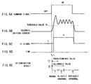
- the solenoid driving current flowing through the current detector 34 in the control circuit 3 is compared with a threshold value Th, so that the DI signal (see Fig.6C) as a logical signal is outputted to be provided to the ECC 2.
- the DI signal can be easily obtained by the comparison with the threshold value Th at a comparator (not shown in Fig.5).
- a comparator can be provided on the outside of the current detector 34 or the control circuit 3.
- the DI signal as shown in Fig.6C may be generated by directly providing the solenoid driving current detecting signal in Fig.6B from the current detector 34 to the ECC 2, and by the comparison with the threshold value Th held inside the ECC2 after the conversion from an analog signal into a digital signal at the ECC 2.
- the time interval from the time t 0 to the time t 1 shown in Fig.6D is equivalent to the delay time interval Tpc, Tpo, Tmc, or Tmo in Figs.3 and 4.
- an electronic fuel injection apparatus is arranged such that a driving current flowing through a solenoid of an electromagnetic spill valve is detected, and a state where a delay time interval from a transit point of a command signal provided to a control circuit to a delay point at which the driving current crosses a threshold value is equal to or more than a predetermined value is determined as a slightly abnormal state to invalidate the command signal for a pilot injection, or a state where the delay time interval exceeds an allowable value further larger than the predetermined value is determined as a seriously abnormal state to stop the engine. Therefore, it becomes possible to prevent an abnormal increase of an engine revolution even when a fault occurs in the electromagnetic spill valve per se.
Landscapes
- Engineering & Computer Science (AREA)
- Chemical & Material Sciences (AREA)
- Combustion & Propulsion (AREA)
- Mechanical Engineering (AREA)
- General Engineering & Computer Science (AREA)
- Electrical Control Of Air Or Fuel Supplied To Internal-Combustion Engine (AREA)
- High-Pressure Fuel Injection Pump Control (AREA)
- Fuel-Injection Apparatus (AREA)
Abstract
Description
Claims (5)
- An electronic fuel injection apparatus comprising a control circuit (3) of an electromagnetic spill valve (13) for adjusting a fuel injection quantity in a distribution-type fuel injection pump (1) for a diesel engine, and a computing unit (2) for providing a command signal to the control circuit (3), characterized in that;the control circuit (3) has, on either an inside or outside of the control circuit (3), means for detecting a driving current which flows through a solenoid (14) of the spill valve (13), and means for detecting a delay point at which the driving current detected crosses a threshold value, andthe computing unit (2) has means for determining a state where a delay time interval from a transit point of the command signal to the delay point is equal to or more than a predetermined value as a slightly abnormal state to invalidate the command signal for a pilot injection.
- The electronic fuel injection apparatus as claimed in claim 1 wherein the means for detecting the delay point is provided in the computing unit on the outside of the control circuit.
- The electronic fuel injection apparatus as claimed in claim 1 wherein the computing unit further includes means for determining a state where the delay time interval exceeds an allowable value larger than the predetermined value as a seriously abnormal state to stop the engine.
- The electronic fuel injection apparatus as claimed in claim 2 wherein the computing unit (2) further includes means for determining a state where the delay time interval exceeds an allowable value larger than the predetermined value as a seriously abnormal state to stop the engine.
- The electronic fuel injection apparatus as claimed in one of the preceding claims, further including means (4) for warning the abnormal state.
Applications Claiming Priority (2)
| Application Number | Priority Date | Filing Date | Title |
|---|---|---|---|
| JP11152589A JP2000345901A (en) | 1999-05-31 | 1999-05-31 | Electronic fuel injection device |
| JP15258999 | 1999-05-31 |
Publications (2)
| Publication Number | Publication Date |
|---|---|
| EP1057991A2 true EP1057991A2 (en) | 2000-12-06 |
| EP1057991A3 EP1057991A3 (en) | 2002-10-30 |
Family
ID=15543761
Family Applications (1)
| Application Number | Title | Priority Date | Filing Date |
|---|---|---|---|
| EP00111545A Withdrawn EP1057991A3 (en) | 1999-05-31 | 2000-05-30 | Electronic fuel injection apparatus |
Country Status (3)
| Country | Link |
|---|---|
| US (1) | US6192856B1 (en) |
| EP (1) | EP1057991A3 (en) |
| JP (1) | JP2000345901A (en) |
Cited By (2)
| Publication number | Priority date | Publication date | Assignee | Title |
|---|---|---|---|---|
| EP1598540A3 (en) * | 2004-05-21 | 2009-05-06 | Denso Corporation | Fuel injection apparatus designed to diagnose failure in injection fuel into each cylinder of diesel engine |
| EP1533503B1 (en) * | 2003-11-20 | 2011-09-21 | C.R.F. Società Consortile per Azioni | Device for control of electro-actuators with detection of the instant of end of actuation, and method for detection of the instant of end of actuation of an electro-actuator |
Families Citing this family (11)
| Publication number | Priority date | Publication date | Assignee | Title |
|---|---|---|---|---|
| JP3842002B2 (en) * | 2000-03-01 | 2006-11-08 | 三菱電機株式会社 | Variable discharge fuel supply system |
| ITTO20001228A1 (en) | 2000-12-29 | 2002-06-29 | Fiat Ricerche | FUEL INJECTION SYSTEM FOR AN INTERNAL COMBUSTION ENGINE. |
| ITTO20001227A1 (en) * | 2000-12-29 | 2002-06-29 | Fiat Ricerche | COMMON MANIFOLD INJECTION SYSTEM FOR AN INTERNAL COMBUSTION ENGINE, WITH A FUEL PRE-DOSING DEVICE. |
| JP4169052B2 (en) * | 2006-06-29 | 2008-10-22 | トヨタ自動車株式会社 | Fuel supply device for internal combustion engine |
| GB2482494A (en) * | 2010-08-03 | 2012-02-08 | Gm Global Tech Operations Inc | Method for estimating an hydraulic dwell time between fuel injection pulses which corrects for injection timing delays |
| DE102012205573B4 (en) * | 2012-04-04 | 2019-06-06 | Continental Automotive Gmbh | Determining the temporal movement behavior of a fuel injector based on an evaluation of the time course of various electrical parameters |
| JP5988031B2 (en) * | 2012-11-05 | 2016-09-07 | 三菱自動車工業株式会社 | Abnormality judgment device for high-pressure pump |
| DE112014002856B4 (en) * | 2013-07-10 | 2019-08-01 | Hitachi Automotive Systems, Ltd. | Control device for internal combustion engine |
| DE102014209587B4 (en) * | 2014-05-20 | 2016-03-31 | Continental Automotive Gmbh | Characterization of a measurement channel for measuring a feedback signal generated by an operating fuel injector |
| DE102017120416A1 (en) * | 2017-09-05 | 2017-12-21 | FEV Europe GmbH | METHOD FOR OPERATING AN INJECTOR |
| US11542885B2 (en) * | 2018-07-03 | 2023-01-03 | Hitachi Astemo, Ltd. | Load drive circuit and load drive system |
Family Cites Families (18)
| Publication number | Priority date | Publication date | Assignee | Title |
|---|---|---|---|---|
| DE2900420A1 (en) * | 1979-01-08 | 1980-07-24 | Bosch Gmbh Robert | DEVICE FOR CONTROLLING THE CURRENT BY AN ELECTROMAGNETIC CONSUMER, IN PARTICULAR BY AN ELECTROMAGNETICALLY OPERATING INJECTION VALVE OF AN INTERNAL COMBUSTION ENGINE |
| JPS635140A (en) * | 1986-06-24 | 1988-01-11 | Diesel Kiki Co Ltd | Injection control method for fuel injection pump |
| DE3703438A1 (en) * | 1987-02-05 | 1988-08-18 | Bosch Gmbh Robert | FUEL INJECTION PUMP FOR INTERNAL COMBUSTION ENGINES |
| JP2521086B2 (en) * | 1987-04-06 | 1996-07-31 | 株式会社ゼクセル | Control device for fuel injection pump |
| FR2616930B1 (en) * | 1987-06-22 | 1995-06-30 | Renault | SAFETY CONTROL DEVICE OF AN ACTUATOR OF THE SOLENOID SWING SOLENOID TYPE |
| DE3722151A1 (en) * | 1987-07-04 | 1989-01-12 | Bosch Gmbh Robert | FUEL INJECTION PUMP |
| JPH0233865A (en) | 1988-07-22 | 1990-02-05 | Toshiba Corp | Cell voltage controller for fuel cell power generating plant |
| DE3844367A1 (en) * | 1988-12-30 | 1990-07-05 | Bosch Gmbh Robert | FUEL INJECTION PUMP FOR INTERNAL COMBUSTION ENGINES |
| DE4016309A1 (en) * | 1990-05-21 | 1991-11-28 | Bosch Gmbh Robert | FUEL INJECTION PUMP FOR INTERNAL COMBUSTION ENGINES |
| DE4032279A1 (en) * | 1990-10-11 | 1992-04-16 | Bosch Gmbh Robert | Fuel injection pump for IC engine - has suction and delivery stroke controlled by electrically operated valve across fuel duct |
| DE69331475T2 (en) * | 1992-08-20 | 2002-07-11 | Toyota Jidosha K.K., Toyota | Fuel injection regulator for internal combustion engines. |
| US5325837A (en) * | 1992-11-19 | 1994-07-05 | Robert Bosch Gmbh | Fuel injection apparatus for internal combustion engines |
| JP3266953B2 (en) * | 1992-12-16 | 2002-03-18 | 株式会社デンソー | Pilot injection device |
| JP3265812B2 (en) * | 1994-03-30 | 2002-03-18 | 株式会社デンソー | Fuel injection control device for internal combustion engine |
| US5469825A (en) * | 1994-09-19 | 1995-11-28 | Chrysler Corporation | Fuel injector failure detection circuit |
| GB9509610D0 (en) * | 1995-05-12 | 1995-07-05 | Lucas Ind Plc | Fuel system |
| JP3596205B2 (en) * | 1996-03-22 | 2004-12-02 | 株式会社デンソー | Solenoid valve drive |
| SG71052A1 (en) | 1996-10-18 | 2000-03-21 | Komag Inc | Magnetic alloy having a structured nucleation layer and method for manufacturing same |
-
1999
- 1999-05-31 JP JP11152589A patent/JP2000345901A/en not_active Withdrawn
-
2000
- 2000-05-23 US US09/576,538 patent/US6192856B1/en not_active Expired - Fee Related
- 2000-05-30 EP EP00111545A patent/EP1057991A3/en not_active Withdrawn
Cited By (2)
| Publication number | Priority date | Publication date | Assignee | Title |
|---|---|---|---|---|
| EP1533503B1 (en) * | 2003-11-20 | 2011-09-21 | C.R.F. Società Consortile per Azioni | Device for control of electro-actuators with detection of the instant of end of actuation, and method for detection of the instant of end of actuation of an electro-actuator |
| EP1598540A3 (en) * | 2004-05-21 | 2009-05-06 | Denso Corporation | Fuel injection apparatus designed to diagnose failure in injection fuel into each cylinder of diesel engine |
Also Published As
| Publication number | Publication date |
|---|---|
| US6192856B1 (en) | 2001-02-27 |
| JP2000345901A (en) | 2000-12-12 |
| EP1057991A3 (en) | 2002-10-30 |
Similar Documents
| Publication | Publication Date | Title |
|---|---|---|
| US6192856B1 (en) | Electronic fuel injection apparatus | |
| EP1703107B1 (en) | Control apparatus of direct injection internal combustion engine | |
| US5825216A (en) | Method of operating a drive circuit for a solenoid | |
| JP2009115009A (en) | Post-stop fuel pressure control device for in-cylinder injection engine | |
| US10161342B2 (en) | Control device for high-pressure pump | |
| US11466653B2 (en) | Control device for fuel injection valve and fuel injection system | |
| JP5327124B2 (en) | Fuel injection control device | |
| US4469065A (en) | Fuel pump control system for internal combustion engines, having a fail safe function for abnormality in fuel injection valves | |
| JPH06213094A (en) | Fuel injection device for internal combustion engine | |
| JPH06330797A (en) | Fuel injection valve driving circuit for engine | |
| US9316168B2 (en) | Internal combustion engine and control device for fuel pump | |
| CN100422535C (en) | Electronic governor for general-purpose internal combustion engines | |
| US10378501B2 (en) | Systems and method for performing prognosis of fuel delivery systems using solenoid current feedback | |
| US6389901B1 (en) | Diagnostic method for a fuel supply system | |
| EP3376018B1 (en) | System and method for positioning a crankshaft of an engine of a vehicle | |
| JP2910483B2 (en) | Abnormal diagnostic device for fuel injection device | |
| US7156082B2 (en) | Controlling spark for an engine with controllable valves | |
| KR102394549B1 (en) | Method and apparatus for diagnosing engine system | |
| JP7312326B2 (en) | fuel injection controller | |
| EP2169213A2 (en) | Starting system for fuel injection engine | |
| JP2012184686A (en) | Engine control unit | |
| JP3960260B2 (en) | Engine control system | |
| JPH09105349A (en) | Fail-safe device for electronic control unit | |
| JPH11294238A (en) | Fuel control system for diesel engine | |
| JP2006291756A (en) | Solenoid valve drive control device |
Legal Events
| Date | Code | Title | Description |
|---|---|---|---|
| PUAI | Public reference made under article 153(3) epc to a published international application that has entered the european phase |
Free format text: ORIGINAL CODE: 0009012 |
|
| AK | Designated contracting states |
Kind code of ref document: A2 Designated state(s): AT BE CH CY DE DK ES FI FR GB GR IE IT LI LU MC NL PT SE |
|
| AX | Request for extension of the european patent |
Free format text: AL;LT;LV;MK;RO;SI |
|
| PUAL | Search report despatched |
Free format text: ORIGINAL CODE: 0009013 |
|
| AK | Designated contracting states |
Kind code of ref document: A3 Designated state(s): AT BE CH CY DE DK ES FI FR GB GR IE IT LI LU MC NL PT SE |
|
| AX | Request for extension of the european patent |
Free format text: AL;LT;LV;MK;RO;SI |
|
| 17P | Request for examination filed |
Effective date: 20030114 |
|
| 17Q | First examination report despatched |
Effective date: 20030310 |
|
| AKX | Designation fees paid |
Designated state(s): DE FR GB |
|
| STAA | Information on the status of an ep patent application or granted ep patent |
Free format text: STATUS: THE APPLICATION IS DEEMED TO BE WITHDRAWN |
|
| 18D | Application deemed to be withdrawn |
Effective date: 20030722 |