EP1057594B1 - Ensemble d'outil manuel de secours - Google Patents
Ensemble d'outil manuel de secours Download PDFInfo
- Publication number
- EP1057594B1 EP1057594B1 EP00304584A EP00304584A EP1057594B1 EP 1057594 B1 EP1057594 B1 EP 1057594B1 EP 00304584 A EP00304584 A EP 00304584A EP 00304584 A EP00304584 A EP 00304584A EP 1057594 B1 EP1057594 B1 EP 1057594B1
- Authority
- EP
- European Patent Office
- Prior art keywords
- handle
- locking pin
- cylindrical
- bore
- semicircular
- Prior art date
- Legal status (The legal status is an assumption and is not a legal conclusion. Google has not performed a legal analysis and makes no representation as to the accuracy of the status listed.)
- Expired - Lifetime
Links
Images

Classifications
-
- A—HUMAN NECESSITIES
- A62—LIFE-SAVING; FIRE-FIGHTING
- A62B—DEVICES, APPARATUS OR METHODS FOR LIFE-SAVING
- A62B3/00—Devices or single parts for facilitating escape from buildings or the like, e.g. protection shields, protection screens; Portable devices for preventing smoke penetrating into distinct parts of buildings
- A62B3/005—Rescue tools with forcing action
-
- B—PERFORMING OPERATIONS; TRANSPORTING
- B25—HAND TOOLS; PORTABLE POWER-DRIVEN TOOLS; MANIPULATORS
- B25C—HAND-HELD NAILING OR STAPLING TOOLS; MANUALLY OPERATED PORTABLE STAPLING TOOLS
- B25C11/00—Nail, spike, and staple extractors
-
- B—PERFORMING OPERATIONS; TRANSPORTING
- B25—HAND TOOLS; PORTABLE POWER-DRIVEN TOOLS; MANIPULATORS
- B25F—COMBINATION OR MULTI-PURPOSE TOOLS NOT OTHERWISE PROVIDED FOR; DETAILS OR COMPONENTS OF PORTABLE POWER-DRIVEN TOOLS NOT PARTICULARLY RELATED TO THE OPERATIONS PERFORMED AND NOT OTHERWISE PROVIDED FOR
- B25F1/00—Combination or multi-purpose hand tools
-
- B—PERFORMING OPERATIONS; TRANSPORTING
- B25—HAND TOOLS; PORTABLE POWER-DRIVEN TOOLS; MANIPULATORS
- B25G—HANDLES FOR HAND IMPLEMENTS
- B25G1/00—Handle constructions
- B25G1/04—Handle constructions telescopic; extensible; sectional
Definitions
- the present invention relates to a manual emergency tool assembly of the typed used for instance by fire persons and rescue squad personnel. More particularly it relates to a manual tool assembly having two operating heads, each of which is designed for different uses, and each of which has a handle.
- the handles are designed to be telescopic with respect to each other, and may be secured to each other in various moveable and fixed positions.
- Forcible entry tools have been provided in the past for use by firepersons and other emergency personnel.
- One such tool is shown in U.S. Patent No. 3,219, 316 - Fried.
- the tool shown in that patent has been manufactured by the assignee of this invention.
- the forcible entry tool set forth in the Fried patent comprised two tools, each of which was provided with a handle. One of the handles is received in a bore in the other in a telescoping arrangement.
- a spring biased latch pin was provided to secure the handles in a fully retracted position with respect to each other.
- a pair of spring biased latch pins were also provided to secure the handle to the chopping blade in two alternate positions which were at right angles to each other.
- the forcible entry tool shown in the Fried patent provided for securing the handles to each other only in the fully retracted position. Further, the spring biased latch pins were subject to wear, the spring was subject to fatigue, and operation could be impaired by foreign material entering the bore housing the spring biased latch pin.
- an emergency work tool having an improved arrangement for securing the handles to each other in multiple fixed and variable positions for greater versatility in use. It would be further advantageous that the securing arrangement for securing the handles to each other be more robust than that provided in prior devices, and that the securing arrangement be assembled of components less subject to wear than the securing arrangements of prior devices. Thus, it has been found desirable to improve the forcible entry tool described in the previously mentioned Fried patent to enhance its uses and to improve upon the securing arrangement for connecting the handles of the two tools to each other.
- An improved assembly may comprise two tools, each provided with a handle.
- the handles are telescopic with respect to each other, and may be secured in various movable and fixed positions with respect to each other.
- This invention may provide a securing arrangement for securing the handles with respect to each other, which is readily operated by a user of the tool.
- This invention may provide a securing arrangement for securing the handles with respect to each other, which is robust and not readily subject to detrimental wear, which would adversely effect its performance.
- This invention may also provide a securing arrangement for securing the handles with respect to each other, wherein a manual actuating element of the securing arrangement is generally protected from damage during both use and storage of the emergency tool assembly.
- An emergency tool assembly in accordance with this invention includes a pair of tools, each of which is provided with a handle.
- One of the handles is provided with a cylindrical bore which receives a cylindrical handle provided on the other tool.
- the tool having the handle with a cylindrical bore is provided with a securing arrangement housing at the end of the cylindrical handle opposite the tool head.
- the securing arrangement housing includes a recessed area in one of its outer faces for receiving a manual operating lever.
- the manual operating lever is connected to a first rotatable cylindrical locking pin which is received in a bore formed in the securing arrangement housing, which bore is perpendicular to and partially intersects the cylindrical bore for receiving the cylindrical handle of the other tool.
- the first rotatable cylindrical locking pin is provided with a semicircular notch which may be aligned with the cylindrical bore upon rotation of the pin by the manual operating lever, such that the cylindrical handle may reciprocate or telescope in the cylindrical bore.
- the cylindrical handle is provided with a semicircular notch which is aligned with the first locking pin when the tool handles are fully retracted with respect to each other.
- the first locking pin may be rotated, by the manual operating lever, to face the semicircular notch in the first locking pin away from the cylindrical handle, so that a portion of the locking pin is positioned in the semicircular notch in the cylindrical handle, thus locking the two handles to each other in a fully retracted position with respect to each other.
- a second fixed locking pin may be provided in the securing arrangement housing, on the diametrically opposite side of the cylindrical bore with respect to the first rotatable locking pin, and in a position perpendicular to and partially intersecting the cylindrical bore.
- a first elongated segmental shaped notch may be provided in the cylindrical handle on the diametrically opposite the first semicircular notch.
- the second fixed locking pin may be received in the first elongated segmental shaped notch.
- a circumferential semicircular groove is formed in the cylindrical handle at the end of the first elongated segmental shaped notch closes to the free end of the handle.
- a second elongated segmental shaped notch is formed in the cylindrical handle, between the free end of the cylindrical handle and the circumferential semicircular groove, on the diametrically opposite side of the handle from the first elongated segmental shaped notch.
- Additional semicircular notches similar to the first semicircular notch may be formed in the cylindrical handle on the diametrically opposite side of the first elongated segmental shaped notch, intermediate its length, to permit the handles to be locked to each other in various telescoped or retracted positions.
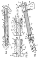
- the manual emergency tool assembly 10 of this invention includes a prying claw 12 and a head 14 which includes a blade 16 and a pike 18.
- the head 14 is provided with a handle 20 having an outer sleeve 22 formed with longitudinally extending ridges 24, thus providing a surface which is readily grasped in a users hand.
- the outer sleeve 22 is formed of a rubber like material.
- Secured within the outer sleeve 22 is a cylindrical tube 26.
- the cylindrical tube 26 extends within a bore 28 formed in the head 14 and is fixedly secure in the bore 28.
- a securing arrangement housing 30 Secured to the end of the cylindrical tube 26 opposite the head 14 is a securing arrangement housing 30 which is provided with a mechanism for locking the handle 20 of head 14 to a solid cylindrical handle 32 which is secured to the prying claw 12 by a roll pin 34 as best seen in Fig. 2.
- Side 36 of housing 30 is provided with a oval shaped depression 38 for receiving manual operating lever 40 which is secured to a rotatable cylindrical locking pin 42 for rotation therewith.
- the locking pin 42 is received in a bore 44 formed in housing 30.
- the end of the locking pin 42 opposite the lever 40 is provided with a circumferential groove for receiving a snap ring 45 to secure the locking pin 42 in the bore 44.
- a pair of depressions, one of which 47 is shown, are formed in the oval shaped depression 38 to be engaged by a spring loaded detent in the lever 40, to secure the lever in positions shown in FIGS. 2A and 2B.
- the locking pin 42 is provided with a semicircular notch 46 having a radius corresponding to that of the internal diameter of the cylindrical tube 26. When the notch 46 is facing the cylindrical handle 32, the locking pin 42 does not restrict the movement of the cylindrical handle 32 with respect to the cylindrical tube 26.
- the solid cylindrical handle 32 secured to the prying claw 12 by the roll pin 34 received in aligned holes in both members, is provided with a plurality of semicircular grooves to be engaged by the rotatable locking pin 42 for securing the solid cylindrical handle 32 and the handle 20 in different fixed positions with respect to each other.
- the semicircular notch 46 in locking pin 42 is facing away from the cylindrical handle 32, such that the rotatable locking pin 42 is engaged in a semicircular notch 50 in handle 32, thus locking the handles in a fully retracted position with respect to each other.
- Rotating locking pin 42 to the position shown in Fig.
- handles 20 and 32 are not restricted in movement with respect to each other by the locking pin 42.
- engagement of a fixed locking pin 52 in an elongated segmental shaped slot 54 in handle 32 limits the reciprocal movement of the two handles with respect to each other to the length of the elongated slot 54.
- the fixed locking pin 52 is provided with a head 53 at one end and a groove at the other end to receive snap ring 55 which secure the locking pin 52 in a bore in the housing 30.
- a semicircular notch 56 is provided in the cylindrical handle 32 close to the end 58 of the elongated slot 54 opposite the end to which the prying claw 12 is secured. If locking pin 42 is rotated to be positioned in the semicircular notch 56, the handles are secured in a fixed extended position with respect to each other, thereby providing a longer operating handle for both of the operating heads.
- the handles 20 and 32 are moved apart from each other until the fixed locking pin 52 is at the end 58 of the elongated slot 54.
- a circumferential semicircular groove 60 is provided at the end 58 of elongated slot 54.
- additional semicircular notches 64 and 66 may be formed in the handle 32, intermediate the length of elongated slot 54.
- Locking pin 42 may be rotated to be positioned in one of the semicircular notches 64 or 66, to thereby secure the handles 20 and 32 in intermediate extended positions with respect to each other.
- the tool may be compactly stored and also used in operations not requiring greater leverage than that provided by the retracted handle length.
- the handles When the handle 32 and shaft 34 are rotated to the position shown in Figs. 2B, and 6, the handles may be reciprocated with respect to each other through the length of elongated slot 54.
- Such reciprocal movement is useful for instance in driving the prying claw between two members, such as a door and a door frame.
- the handles are rigidly secured to each other so as to provide a longer operating handle for increase leverage when using either the prying claw 12 or the head 14.
- the two handles may be separated from each other, such that the two tools may be independently used. Further, the free end of cylindrical handle 32 may be placed in a hole 68 formed in the head 14, to provide leverage for twisting the blade 16 about its free end, which may be jammed between two members to pry them apart.
Claims (6)
- Ensemble d'outil manuel de secours comportant :A. une première tête de fonctionnement (12) ayant un premier manche (32) se prolongeant en provenance de celle-ci, ledit premier manche ayant une forme cylindrique,B. une deuxième tête de fonctionnement (14) ayant un deuxième manche (20) se prolongeant en provenance de celle-ci, ledit deuxième manche ayant un alésage cylindrique à l'intérieur de celui-ci destiné à recevoir ledit premier manche selon une relation télescopique, ledit ensemble d'outil caractérisé par une première entaille semi-circulaire (50) étant formée dans ledit premier manche de manière adjacente à ladite première tête de fonctionnement, et par un logement de dispositif d'assujettissement (30) attaché à l'extrémité dudit deuxième manche de manière opposée à ladite deuxième tête de fonctionnement, ledit logement de dispositif d'assujettissement ayant un alésage cylindrique à l'intérieur de celui-ci destiné à recevoir ledit premier manche, une goupille d'arrêt cylindrique rotative (42) étant reçue dans un premier alésage (44) dans ledit logement de dispositif d'assujettissement, ledit premier alésage étant perpendiculaire par rapport à l'alésage cylindrique dans ledit deuxième manche et entrecroisant partiellement celui-ci, ladite goupille d'arrêt cylindrique rotative ayant une entaille semi-circulaire (46) à l'intérieur de celle-ci qui dans une première position est alignée sur l'alésage cylindrique dans ledit deuxième manche, de telle manière que ledit premier manche peut être reçu de manière télescopique et être animé d'un mouvement de va-et-vient dans ledit deuxième manche, ladite première entaille semi-circulaire étant alignée sur ladite goupille d'arrêt cylindrique rotative, ladite goupille d'arrêt cylindrique peut être tournée sur une deuxième position afin que l'entaille semi-circulaire dans ladite goupille d'arrêt cylindrique tourne le dos audit premier manche, de telle manière qu'une portion de la goupille d'arrêt est positionnée dans ladite première entaille semi-circulaire afin d'assujettir ledit premier manche et ledit deuxième manche en une position entièrement télescopée l'un par rapport à l'autre.
- Ensemble d'outil manuel de secours selon la revendication 1, dans lequel une dépression (38) est réalisée dans la surface extérieure dudit logement de dispositif d'assujettissement afin de recevoir un levier de fonctionnement manuel (40) assujetti sur ladite goupille d'arrêt cylindrique rotative à des fins de rotation avec celle-ci.
- Ensemble d'outil manuel de secours selon la revendication 2, dans lequel un dispositif d'encliquetage (47) est mis en oeuvre sur ledit logement de dispositif d'assujettissement et sur ledit levier de fonctionnement manuel en vue de tenir ledit levier de fonctionnement manuel sur ladite première position ou sur ladite deuxième position.
- Ensemble d'outil manuel de secours selon l'une quelconque des revendications précédentes, dans lequel la première tête de fonctionnement comporte par ailleurs :une première fente allongée en forme de segment (54) étant réalisée à l'intérieur de celle-ci du côté diamétralement opposé dudit premier manche par rapport à ladite première entaille semi-circulaire, et espacée de manière axiale par rapport à ladite première entaille semi-circulaire et se prolongeant vers l'extrémité libre dudit premier manche,une rainure semi-circulaire se prolongeant de manière circonférentielle (60) étant réalisée à l'intérieur de celle-ci au niveau de l'extrémité de ladite première fente allongée en forme de segment plus près de l'extrémité libre dudit premier manche,une deuxième fente allongée en forme de segment (62) étant réalisée à l'intérieur de celle-ci du même côté dudit premier manche que celui de ladite première entaille semi-circulaire et se prolongeant en provenance de ladite rainure semi-circulaire se prolongeant de manière circonférentielle vers l'extrémité libre dudit premier manche,et ladite deuxième tête de fonctionnement comporte par ailleurs :une goupille d'arrêt fixe (52) reçue dans un deuxième alésage dans ledit logement de dispositif d'assujettissement, ledit deuxième alésage étant perpendiculaire par rapport à l'alésage cylindrique et entrecroisant partiellement celui-ci, de telle manière qu'une portion de ladite goupille d'arrêt fixe se prolonge dans ledit alésage cylindrique, ledit deuxième alésage étant situé plus près dudit deuxième manche par rapport audit premier alésage, et du côté diamétralement opposé dudit alésage cylindrique dans ledit deuxième manche, ce par quoi, pour insérer ledit premier manche dans l'alésage cylindrique dans ledit deuxième manche, ladite goupille d'arrêt cylindrique rotative est tournée pour aligner l'entaille semi-circulaire dans celle-ci sur l'alésage cylindrique, et ladite deuxième fente allongée en forme de segment est alignée sur ladite goupille d'arrêt fixe, ledit premier manche étant inséré jusqu'à ce que la goupille d'arrêt fixe se situe dans la rainure semi-circulaire se prolongeant de manière circonférentielle, les manches étant tournés l'un par rapport à l'autre jusqu'à ce que la goupille d'arrêt fixe soit alignée sur la première fente allongée en forme de segment, ceci insérant plus encore ledit premier manche dans ledit deuxième manche jusqu'à ce que la première entaille semi-circulaire soit alignée sur ladite goupille d'arrêt cylindrique rotative, ceci tournant ladite goupille d'arrêt cylindrique afin que l'entaille semi-circulaire dans ladite goupille d'arrêt cylindrique tourne le dos audit premier manche, de telle manière qu'une portion de la goupille d'arrêt est positionnée dans ladite première entaille semi-circulaire en vue d'assujettir ledit premier manche et ledit deuxième manche en une position entièrement télescopée l'un par rapport à l'autre.
- Ensemble d'outil manuel de secours selon la revendication 4, dans lequel une deuxième entaille semi-circulaire (56) est réalisée dans ledit premier manche de manière diamétralement opposée à ladite première entaille allongée en forme de segment, et près de ladite rainure semi-circulaire se prolongeant de manière circonférentielle, ce par quoi, ladite goupille d'arrêt fixe étant située dans ladite rainure semi-circulaire se prolongeant de manière circonférentielle, ladite goupille d'arrêt cylindrique rotative peut être tournée afin que l'entaille semi-circulaire dans ladite goupille d'arrêt cylindrique tourne le dos audit premier manche, de telle manière qu'une portion de la goupille d'arrêt est positionnée dans ladite deuxième entaille semi-circulaire en vue d'assujettir ledit premier manche et ledit deuxième manche en une position sortie l'un par rapport à l'autre.
- Ensemble d'outil manuel de secours selon la revendication 5, dans lequel au moins une troisième entaille semi-circulaire (64, 66) est réalisée dans ledit premier manche de manière diamétralement opposée à ladite première entaille allongée en forme de segment et entre ladite première entaille semi-circulaire et ladite deuxième entaille semi-circulaire, ce par quoi, ladite goupille d'arrêt fixe étant située dans ladite première entaille allongée en forme de segment, ladite goupille d'arrêt cylindrique rotative peut être tournée afin que l'entaille semi-circulaire dans ladite goupille d'arrêt cylindrique tourne le dos audit premier manche, de telle manière qu'une portion de la goupille d'arrêt est positionnée dans cette dite entaille semi-circulaire en vue d'assujettir ledit premier manche et ledit deuxième manche en une position partiellement sortie l'un par rapport à l'autre.
Applications Claiming Priority (2)
| Application Number | Priority Date | Filing Date | Title |
|---|---|---|---|
| US323318 | 1999-06-01 | ||
| US09/323,318 US6397420B1 (en) | 1999-06-01 | 1999-06-01 | Manual emergency tool assembly |
Publications (3)
| Publication Number | Publication Date |
|---|---|
| EP1057594A2 EP1057594A2 (fr) | 2000-12-06 |
| EP1057594A3 EP1057594A3 (fr) | 2002-10-23 |
| EP1057594B1 true EP1057594B1 (fr) | 2007-01-17 |
Family
ID=23258682
Family Applications (1)
| Application Number | Title | Priority Date | Filing Date |
|---|---|---|---|
| EP00304584A Expired - Lifetime EP1057594B1 (fr) | 1999-06-01 | 2000-05-31 | Ensemble d'outil manuel de secours |
Country Status (4)
| Country | Link |
|---|---|
| US (1) | US6397420B1 (fr) |
| EP (1) | EP1057594B1 (fr) |
| DE (1) | DE60032965T2 (fr) |
| DK (1) | DK1057594T3 (fr) |
Cited By (1)
| Publication number | Priority date | Publication date | Assignee | Title |
|---|---|---|---|---|
| US11958176B2 (en) | 2020-05-07 | 2024-04-16 | Andrew Zanoni | Multi-tool combining firefighting implements |
Families Citing this family (30)
| Publication number | Priority date | Publication date | Assignee | Title |
|---|---|---|---|---|
| US20040261188A1 (en) * | 2003-06-28 | 2004-12-30 | Mathis Richard Jerome | Combination firefighter tool |
| US20050005457A1 (en) * | 2003-07-09 | 2005-01-13 | Wensel Dan L. | Multipurpose firefighting and demolition implement |
| US20070029101A1 (en) * | 2005-08-05 | 2007-02-08 | Paul Croas | Hammerhead forcible entry tool used to defeat burglar bars |
| US7735172B2 (en) * | 2005-09-23 | 2010-06-15 | Fire Hardware, Llc | Multi-purpose firefighting tool |
| US20080022815A1 (en) * | 2006-07-26 | 2008-01-31 | Farrell Terry C | Firefighter tool |
| US8061239B2 (en) * | 2006-07-26 | 2011-11-22 | Channellock, Inc. | Rescue tool |
| US8485074B2 (en) * | 2006-07-26 | 2013-07-16 | Channellock, Inc. | Firefighter tool |
| US7565711B1 (en) * | 2006-08-17 | 2009-07-28 | Michael William Schamadan | Combination firefighting tool |
| KR200445144Y1 (ko) * | 2007-12-20 | 2009-07-02 | 조민수 | 다목적 3단 파괴기 |
| US8505876B2 (en) | 2008-01-18 | 2013-08-13 | Gränsfors Smide i Gnarp AB | Forcible entry tool |
| CA2712259A1 (fr) | 2008-01-18 | 2009-07-23 | Graensfors Smide I Gnarp Ab | Outil pour forcer une porte |
| US8100035B1 (en) | 2008-07-24 | 2012-01-24 | Clay Reece Smith | Tool with slideable weight |
| US8365332B2 (en) * | 2008-11-07 | 2013-02-05 | Milwaukee Electric Tool Corporation | Utility bar |
| USD769100S1 (en) | 2009-11-06 | 2016-10-18 | Milwaukee Electric Tool Corporation | Utility bar |
| GB2489470A (en) * | 2011-03-29 | 2012-10-03 | West Midlands Locksmiths Ltd | Door opening tool and method |
| USD786638S1 (en) * | 2011-04-11 | 2017-05-16 | Robert G. Lofley, SR. | Tool |
| CA2795968C (fr) * | 2011-11-16 | 2016-06-07 | Les Bronee | Un marteau pour montant et construction |
| US9021642B1 (en) * | 2012-10-09 | 2015-05-05 | Darin Andrew Fox | Combination axe, sledge hammer and pick |
| US20140131644A1 (en) * | 2012-11-13 | 2014-05-15 | Stanley Black & Decker Inc. | Multipurpose prying tool |
| USD752407S1 (en) * | 2014-03-28 | 2016-03-29 | Rmj Tactical, Llc | Tomahawk |
| USD785433S1 (en) * | 2014-04-16 | 2017-05-02 | Clint Bowring | Firefighter's carry ax |
| US10427286B2 (en) * | 2014-04-30 | 2019-10-01 | Scott McCann | Multi-use ax |
| USD795668S1 (en) | 2016-05-13 | 2017-08-29 | Gregory Poulos | Breaching tool |
| USD795037S1 (en) * | 2016-06-16 | 2017-08-22 | OnScene Solutions, LLC | Multi-use firefighting tool |
| USD823660S1 (en) * | 2017-03-08 | 2018-07-24 | The Ontario Knife Company | Fire axe with pry bar entry device |
| USD848233S1 (en) | 2017-04-14 | 2019-05-14 | Scott McCann | Ax |
| USD834909S1 (en) | 2017-05-15 | 2018-12-04 | Greg Poulos LLC | Breaching tool |
| USD863920S1 (en) * | 2018-04-27 | 2019-10-22 | Ou Liu | Multifunctional axe |
| DE102020108193A1 (de) | 2020-03-25 | 2021-09-30 | Airbus Operations Gmbh | Mehrzweckwerkzeug für Flugbegleiter |
| USD987403S1 (en) * | 2021-07-25 | 2023-05-30 | Clarence Russell Casto, Jr. | Light removal tool |
Family Cites Families (14)
| Publication number | Priority date | Publication date | Assignee | Title |
|---|---|---|---|---|
| US2377730A (en) * | 1945-06-05 | Combination tool | ||
| US1030592A (en) * | 1912-03-06 | 1912-06-25 | Millers Falls Co | Telescopic extension-rod. |
| US2382291A (en) * | 1943-04-08 | 1945-08-14 | Allan Blomstrom F | Extensible hand tool |
| US2820626A (en) * | 1956-03-09 | 1958-01-21 | Bert G Hedeen | Brace rod |
| US3219316A (en) * | 1964-05-14 | 1965-11-23 | Fried Emanuel | Forcible entry tool |
| US3489451A (en) * | 1968-04-01 | 1970-01-13 | Leo A Guckenberger | Awning lowering device |
| US3779107A (en) * | 1972-10-19 | 1973-12-18 | T Avery | Ratchet wrench tool head positioner |
| US3883117A (en) * | 1973-10-19 | 1975-05-13 | Earl A Powell | Device for squaring the studs and plate members of a wall section |
| US4701074A (en) * | 1986-04-17 | 1987-10-20 | Wimpey Laboratories Limited | Apparatus for forming a grouted member in deep water |
| US5105493A (en) * | 1989-04-05 | 1992-04-21 | Lugtenaar Thomas K | Firefighting tool set |
| EP0430572A3 (en) * | 1989-11-25 | 1991-11-21 | Hahn & Kolb Gmbh & Co. | Coupling |
| US5176363A (en) * | 1992-04-21 | 1993-01-05 | Bowlin Bob L | Lift bar |
| US5193419A (en) * | 1992-06-15 | 1993-03-16 | Lee Chang Chuan | Wrench with telescopic handle |
| US5428853A (en) * | 1993-12-29 | 1995-07-04 | The Ahrens-Fox Fire Engine Company | Fireman's combination tool assembly |
-
1999
- 1999-06-01 US US09/323,318 patent/US6397420B1/en not_active Expired - Lifetime
-
2000
- 2000-05-31 DK DK00304584T patent/DK1057594T3/da active
- 2000-05-31 EP EP00304584A patent/EP1057594B1/fr not_active Expired - Lifetime
- 2000-05-31 DE DE60032965T patent/DE60032965T2/de not_active Expired - Lifetime
Cited By (1)
| Publication number | Priority date | Publication date | Assignee | Title |
|---|---|---|---|---|
| US11958176B2 (en) | 2020-05-07 | 2024-04-16 | Andrew Zanoni | Multi-tool combining firefighting implements |
Also Published As
| Publication number | Publication date |
|---|---|
| DE60032965T2 (de) | 2007-10-31 |
| DK1057594T3 (da) | 2007-02-26 |
| DE60032965D1 (de) | 2007-03-08 |
| US6397420B1 (en) | 2002-06-04 |
| EP1057594A2 (fr) | 2000-12-06 |
| EP1057594A3 (fr) | 2002-10-23 |
Similar Documents
| Publication | Publication Date | Title |
|---|---|---|
| EP1057594B1 (fr) | Ensemble d'outil manuel de secours | |
| EP0893045B1 (fr) | Mécanisme d'ajustement d'arbre télescopique et rotatif pour outil de jardinage | |
| US3219316A (en) | Forcible entry tool | |
| US7946198B2 (en) | Ratcheting driver with helical drive | |
| US20050025592A1 (en) | Hole saw arbor | |
| EP1712297A1 (fr) | Mecanisme de verrouillage pour tige rallonge | |
| EP1600234A1 (fr) | Outil de coupe électrique | |
| US8973472B2 (en) | Tool extension bar | |
| CH695485A5 (de) | Werkzeughalterung für eine Handwerkzeugmaschine. | |
| US10514049B2 (en) | Hydraulic actuator and torque transmission coupler | |
| EP0105352A1 (fr) | Marteau a point de pivotement reglable | |
| EP0868264B1 (fr) | Outil a main electrique | |
| WO2015061425A1 (fr) | Outil à puissance hydraulique | |
| US4268926A (en) | Rescue tool | |
| US6807883B1 (en) | Torque tool handle for releasable shank | |
| DE10047021A1 (de) | Handwerkzeugmachine mit einer abnehmbaren Werkzeughalterung | |
| US20200306845A1 (en) | Hydraulic device | |
| EP2608936B1 (fr) | Dispositif de machine-outil portative | |
| US20050246901A1 (en) | Reciprocating power tool | |
| EP1259358B1 (fr) | Raccord de manche a balai ou analogue | |
| CN111246972B (zh) | 可换向棘轮扳手 | |
| EP0703044A1 (fr) | Assemblage flexible | |
| EP1759796A1 (fr) | Scie sauteuse avec poignée rotative | |
| US20040045416A1 (en) | Hand tool | |
| EP1457292A1 (fr) | Accouplement outil/tige |
Legal Events
| Date | Code | Title | Description |
|---|---|---|---|
| PUAI | Public reference made under article 153(3) epc to a published international application that has entered the european phase |
Free format text: ORIGINAL CODE: 0009012 |
|
| AK | Designated contracting states |
Kind code of ref document: A2 Designated state(s): AT BE CH CY DE DK ES FI FR GB GR IE IT LI LU MC NL PT SE |
|
| AX | Request for extension of the european patent |
Free format text: AL;LT;LV;MK;RO;SI |
|
| PUAL | Search report despatched |
Free format text: ORIGINAL CODE: 0009013 |
|
| AK | Designated contracting states |
Kind code of ref document: A3 Designated state(s): AT BE CH CY DE DK ES FI FR GB GR IE IT LI LU MC NL PT SE |
|
| AX | Request for extension of the european patent |
Free format text: AL;LT;LV;MK;RO;SI |
|
| RIC1 | Information provided on ipc code assigned before grant |
Free format text: 7B 25G 1/04 A, 7B 25F 1/00 B, 7F 16B 7/10 B, 7F 16B 21/02 B |
|
| 17P | Request for examination filed |
Effective date: 20030423 |
|
| AKX | Designation fees paid |
Designated state(s): AT BE CH CY DE DK ES FI FR GB GR IE IT LI LU MC NL PT SE |
|
| GRAP | Despatch of communication of intention to grant a patent |
Free format text: ORIGINAL CODE: EPIDOSNIGR1 |
|
| GRAS | Grant fee paid |
Free format text: ORIGINAL CODE: EPIDOSNIGR3 |
|
| GRAA | (expected) grant |
Free format text: ORIGINAL CODE: 0009210 |
|
| AK | Designated contracting states |
Kind code of ref document: B1 Designated state(s): AT BE CH CY DE DK ES FI FR GB GR IE IT LI LU MC NL PT SE |
|
| PG25 | Lapsed in a contracting state [announced via postgrant information from national office to epo] |
Ref country code: FI Free format text: LAPSE BECAUSE OF FAILURE TO SUBMIT A TRANSLATION OF THE DESCRIPTION OR TO PAY THE FEE WITHIN THE PRESCRIBED TIME-LIMIT Effective date: 20070117 Ref country code: AT Free format text: LAPSE BECAUSE OF FAILURE TO SUBMIT A TRANSLATION OF THE DESCRIPTION OR TO PAY THE FEE WITHIN THE PRESCRIBED TIME-LIMIT Effective date: 20070117 Ref country code: CH Free format text: LAPSE BECAUSE OF FAILURE TO SUBMIT A TRANSLATION OF THE DESCRIPTION OR TO PAY THE FEE WITHIN THE PRESCRIBED TIME-LIMIT Effective date: 20070117 Ref country code: LI Free format text: LAPSE BECAUSE OF FAILURE TO SUBMIT A TRANSLATION OF THE DESCRIPTION OR TO PAY THE FEE WITHIN THE PRESCRIBED TIME-LIMIT Effective date: 20070117 |
|
| REG | Reference to a national code |
Ref country code: GB Ref legal event code: FG4D |
|
| REG | Reference to a national code |
Ref country code: CH Ref legal event code: EP |
|
| REG | Reference to a national code |
Ref country code: DK Ref legal event code: T3 |
|
| REG | Reference to a national code |
Ref country code: IE Ref legal event code: FG4D |
|
| REF | Corresponds to: |
Ref document number: 60032965 Country of ref document: DE Date of ref document: 20070308 Kind code of ref document: P |
|
| REG | Reference to a national code |
Ref country code: SE Ref legal event code: TRGR |
|
| PG25 | Lapsed in a contracting state [announced via postgrant information from national office to epo] |
Ref country code: ES Free format text: LAPSE BECAUSE OF FAILURE TO SUBMIT A TRANSLATION OF THE DESCRIPTION OR TO PAY THE FEE WITHIN THE PRESCRIBED TIME-LIMIT Effective date: 20070428 |
|
| ET | Fr: translation filed | ||
| PG25 | Lapsed in a contracting state [announced via postgrant information from national office to epo] |
Ref country code: PT Free format text: LAPSE BECAUSE OF FAILURE TO SUBMIT A TRANSLATION OF THE DESCRIPTION OR TO PAY THE FEE WITHIN THE PRESCRIBED TIME-LIMIT Effective date: 20070618 |
|
| REG | Reference to a national code |
Ref country code: CH Ref legal event code: PL |
|
| PLBE | No opposition filed within time limit |
Free format text: ORIGINAL CODE: 0009261 |
|
| STAA | Information on the status of an ep patent application or granted ep patent |
Free format text: STATUS: NO OPPOSITION FILED WITHIN TIME LIMIT |
|
| 26N | No opposition filed |
Effective date: 20071018 |
|
| PG25 | Lapsed in a contracting state [announced via postgrant information from national office to epo] |
Ref country code: BE Free format text: LAPSE BECAUSE OF FAILURE TO SUBMIT A TRANSLATION OF THE DESCRIPTION OR TO PAY THE FEE WITHIN THE PRESCRIBED TIME-LIMIT Effective date: 20070117 |
|
| PG25 | Lapsed in a contracting state [announced via postgrant information from national office to epo] |
Ref country code: MC Free format text: LAPSE BECAUSE OF NON-PAYMENT OF DUE FEES Effective date: 20070531 |
|
| PG25 | Lapsed in a contracting state [announced via postgrant information from national office to epo] |
Ref country code: GR Free format text: LAPSE BECAUSE OF FAILURE TO SUBMIT A TRANSLATION OF THE DESCRIPTION OR TO PAY THE FEE WITHIN THE PRESCRIBED TIME-LIMIT Effective date: 20070418 |
|
| PG25 | Lapsed in a contracting state [announced via postgrant information from national office to epo] |
Ref country code: IE Free format text: LAPSE BECAUSE OF NON-PAYMENT OF DUE FEES Effective date: 20070531 |
|
| PG25 | Lapsed in a contracting state [announced via postgrant information from national office to epo] |
Ref country code: CY Free format text: LAPSE BECAUSE OF FAILURE TO SUBMIT A TRANSLATION OF THE DESCRIPTION OR TO PAY THE FEE WITHIN THE PRESCRIBED TIME-LIMIT Effective date: 20070117 |
|
| PG25 | Lapsed in a contracting state [announced via postgrant information from national office to epo] |
Ref country code: LU Free format text: LAPSE BECAUSE OF NON-PAYMENT OF DUE FEES Effective date: 20070531 |
|
| PG25 | Lapsed in a contracting state [announced via postgrant information from national office to epo] |
Ref country code: IT Free format text: LAPSE BECAUSE OF NON-PAYMENT OF DUE FEES Effective date: 20090531 |
|
| PGRI | Patent reinstated in contracting state [announced from national office to epo] |
Ref country code: IT Effective date: 20110616 |
|
| PGFP | Annual fee paid to national office [announced via postgrant information from national office to epo] |
Ref country code: DK Payment date: 20130529 Year of fee payment: 14 Ref country code: GB Payment date: 20130529 Year of fee payment: 14 Ref country code: SE Payment date: 20130528 Year of fee payment: 14 Ref country code: DE Payment date: 20130529 Year of fee payment: 14 |
|
| PGFP | Annual fee paid to national office [announced via postgrant information from national office to epo] |
Ref country code: IT Payment date: 20130528 Year of fee payment: 14 Ref country code: NL Payment date: 20130527 Year of fee payment: 14 Ref country code: FR Payment date: 20130610 Year of fee payment: 14 |
|
| REG | Reference to a national code |
Ref country code: DE Ref legal event code: R119 Ref document number: 60032965 Country of ref document: DE |
|
| REG | Reference to a national code |
Ref country code: NL Ref legal event code: V1 Effective date: 20141201 |
|
| REG | Reference to a national code |
Ref country code: DK Ref legal event code: EBP Effective date: 20140531 |
|
| GBPC | Gb: european patent ceased through non-payment of renewal fee |
Effective date: 20140531 |
|
| PG25 | Lapsed in a contracting state [announced via postgrant information from national office to epo] |
Ref country code: SE Free format text: LAPSE BECAUSE OF NON-PAYMENT OF DUE FEES Effective date: 20140601 |
|
| REG | Reference to a national code |
Ref country code: SE Ref legal event code: EUG |
|
| REG | Reference to a national code |
Ref country code: DE Ref legal event code: R119 Ref document number: 60032965 Country of ref document: DE Effective date: 20141202 |
|
| PG25 | Lapsed in a contracting state [announced via postgrant information from national office to epo] |
Ref country code: NL Free format text: LAPSE BECAUSE OF NON-PAYMENT OF DUE FEES Effective date: 20141201 |
|
| REG | Reference to a national code |
Ref country code: FR Ref legal event code: ST Effective date: 20150130 |
|
| PG25 | Lapsed in a contracting state [announced via postgrant information from national office to epo] |
Ref country code: DE Free format text: LAPSE BECAUSE OF NON-PAYMENT OF DUE FEES Effective date: 20141202 Ref country code: DK Free format text: LAPSE BECAUSE OF NON-PAYMENT OF DUE FEES Effective date: 20140531 Ref country code: IT Free format text: LAPSE BECAUSE OF NON-PAYMENT OF DUE FEES Effective date: 20140531 |
|
| PG25 | Lapsed in a contracting state [announced via postgrant information from national office to epo] |
Ref country code: FR Free format text: LAPSE BECAUSE OF NON-PAYMENT OF DUE FEES Effective date: 20140602 Ref country code: GB Free format text: LAPSE BECAUSE OF NON-PAYMENT OF DUE FEES Effective date: 20140531 |