EP1057517B1 - Electrochemical oxygen generating system - Google Patents
Electrochemical oxygen generating system Download PDFInfo
- Publication number
- EP1057517B1 EP1057517B1 EP00111668A EP00111668A EP1057517B1 EP 1057517 B1 EP1057517 B1 EP 1057517B1 EP 00111668 A EP00111668 A EP 00111668A EP 00111668 A EP00111668 A EP 00111668A EP 1057517 B1 EP1057517 B1 EP 1057517B1
- Authority
- EP
- European Patent Office
- Prior art keywords
- oxygen generating
- generating system
- oxygen
- oven chamber
- electrochemical
- Prior art date
- Legal status (The legal status is an assumption and is not a legal conclusion. Google has not performed a legal analysis and makes no representation as to the accuracy of the status listed.)
- Expired - Lifetime
Links
Images


Classifications
-
- C—CHEMISTRY; METALLURGY
- C25—ELECTROLYTIC OR ELECTROPHORETIC PROCESSES; APPARATUS THEREFOR
- C25B—ELECTROLYTIC OR ELECTROPHORETIC PROCESSES FOR THE PRODUCTION OF COMPOUNDS OR NON-METALS; APPARATUS THEREFOR
- C25B1/00—Electrolytic production of inorganic compounds or non-metals
- C25B1/01—Products
- C25B1/02—Hydrogen or oxygen
-
- B—PERFORMING OPERATIONS; TRANSPORTING
- B01—PHYSICAL OR CHEMICAL PROCESSES OR APPARATUS IN GENERAL
- B01D—SEPARATION
- B01D53/00—Separation of gases or vapours; Recovering vapours of volatile solvents from gases; Chemical or biological purification of waste gases, e.g. engine exhaust gases, smoke, fumes, flue gases, aerosols
- B01D53/32—Separation of gases or vapours; Recovering vapours of volatile solvents from gases; Chemical or biological purification of waste gases, e.g. engine exhaust gases, smoke, fumes, flue gases, aerosols by electrical effects other than those provided for in group B01D61/00
- B01D53/326—Separation of gases or vapours; Recovering vapours of volatile solvents from gases; Chemical or biological purification of waste gases, e.g. engine exhaust gases, smoke, fumes, flue gases, aerosols by electrical effects other than those provided for in group B01D61/00 in electrochemical cells
-
- Y—GENERAL TAGGING OF NEW TECHNOLOGICAL DEVELOPMENTS; GENERAL TAGGING OF CROSS-SECTIONAL TECHNOLOGIES SPANNING OVER SEVERAL SECTIONS OF THE IPC; TECHNICAL SUBJECTS COVERED BY FORMER USPC CROSS-REFERENCE ART COLLECTIONS [XRACs] AND DIGESTS
- Y02—TECHNOLOGIES OR APPLICATIONS FOR MITIGATION OR ADAPTATION AGAINST CLIMATE CHANGE
- Y02P—CLIMATE CHANGE MITIGATION TECHNOLOGIES IN THE PRODUCTION OR PROCESSING OF GOODS
- Y02P20/00—Technologies relating to chemical industry
- Y02P20/10—Process efficiency
- Y02P20/129—Energy recovery, e.g. by cogeneration, H2recovery or pressure recovery turbines
Definitions
- This invention relates to devices for separating oxygen from more complex gasses such as air which contains oxygen, and delivering the separated-oxygen at an elevated pressure for use immediately, or for storage and use later. More particularly, the invention relates to solid state electrochemical devices for separating oxygen from more complex gasses to produce the desired oxygen and delivering the oxygen at elevated pressures up to and exceeding 137.9 Bar (2000 psig).
- oxygen can be removed from more complex gasses, such as air, by an electrochemical process of ionizing the oxygen molecules, transporting the oxygen ions through a solid electrolyte and reforming the oxygen molecules on an opposite electrolyte surface.
- An electrical potential is applied to a suitable catalyzing electrode coating applied to the surface of the electrolyte which is porous to oxygen molecules and which acts to disassociate oxygen molecules into oxygen ions at its interface with the electrolyte.
- the oxygen ions are transported through the electrolyte to the opposite surface, which is also coated with a catalyzing electrode and electrically charged with the opposite electrical potential that removes the excess electrons from the oxygen ions, and oxygen molecules are reformed.
- WO-A-9948595 discloses an oxygen generating system comprising an oxygen generator having an oxygen ion conducting honeycomb structure and a heat exchanger thermally coupled to the oxygen generator.
- US-A-5186793 discloses an oxygen concentration system for producing oxygen from air comprising an electrochemical oxygen concentrator mounted within an inner housing having the form of an annulus.
- an object of the present invention to provide an electrochemical oxygen generating system which can provide high-pressure oxygen.
- Yet another object of the present invention is to provide a control system for controlling oven chamber temperatures.
- Another object of the present invention is to provide a unique mounting and electrical interconnection structure for supporting the oxygen generating modules and provide electrical power thereto.
- Another object of the present invention is to provide an oxygen generating system capable of using contaminated air and capable of filtering the contaminated air and providing breathable high purity oxygen gas.
- Still another object of the present invention is to provide an oxygen generating system capable of using air contaminated with biological agents and/or other toxic substances and capable of generating breathable high purity oxygen gas.
- Still another object of the present invention is to provide a method of sealing a ceramic tube to a ceramic module to allow each to thermally expand and contract without cracking.
- an electrochemical oxygen generating system including an oven chamber having a fresh air inlet and a depleted air outlet, at least one ceramic oxygen generating module located in the oven chamber and having an oxygen outlet, a heater mounted in the oven chamber, a heat exchanger positioned between the fresh air inlet and the oven chamber, a controller for providing electrical power to the at least one ceramic oxygen generating module and for controlling the heater and a plurality of adjustable dampers being located between said fresh air inlet and said oven chamber.
- the proposed invention is suitable for, but is not limited to, the delivery of high purity oxygen for many medical, semiconductor and industrial applications as well as the filtration of chemical and biological agents in civil and military environments.
- Yet another object of the present invention is to provide an electrochemical oxygen generating system capable of utilizing an air supply that contains chemical and/or biological contaminants including an oven chamber having an air inlet from the air supply and a depleted air outlet, at least one ceramic oxygen generating module located in the oven chamber and having an oxygen outlet, a heater mounted in the oven chamber, a heat exchanger positioned between the fresh air inlet and the oven chamber, and a controller for providing electrical power to the at least one ceramic oxygen generating module and for controlling the heater, wherein oxygen gas provided to the oxygen outlet is free of the chemical and/or biological contaminants.
- FIG 1 illustrates a schematic of a complete oxygen generating system 10 utilizing an electrochemical-oxygen generator in the form of a modular ceramic oxygen generator.
- This schematic depicts a power supply and controller 20 that supplies electrical power to an oven heater 24 to raise the temperature within the operating range of an oxygen-generating module assembly 22.
- the oxygen-generating module 22 assembly can include or more oxygen-generating modules such as those disclosed in U.S. Patent No. 5,871,624 (publication number US000005871624A ) and Serial No. 09/010,828 (publication number US000005985113A ).
- the temperature range in an oven chamber 26 may be about 500 to 800 degrees Celsius, depending on the materials used to construct the oxygen-generating module assembly 22.
- the oxygen-generating modules 22 are positioned in the oven chamber 26. After the oven chamber 26 reaches the minimum preferred operating temperature, as detected by at least thermocouple 28 mounted in the oven chamber 26, the controller 20 begins to apply electrical power to a fan motor 30 to deliver oxygen-laden air through a counter-flow heat exchanger 32 into the oven 26 chamber to a module assembly 21 including at least one module 22.
- the controller 20 also delivers electrical power to the modules 22, and oxygen is electrochemically generated, as taught in U.S. Patent No. 5,871,624 (publication number US000005871624A ) and Application Serial No.
- 09/010,828 publication number US000005985113A .
- the amount of electrical power can be varied. As electrical power is delivered to the modules 22 and oxygen is generated, electrical resistance within the modules 22 generates additional heat. To compensate for this additional heat, the controller 20 reduces power to the oven heater 24, to maintain the desired nominal operating temperature in the oven chamber 26.
- the oxygen being generated is delivered to a product plenum 34, which acts as a temporary oxygen storage vessel.
- the oxygen is delivered from the product plenum 34 to a low-pressure regulator 36, final filter 38, check valve 40, flow meter 42, and lastly a user-adjustable valve 44 for immediate use, for example, by a patient.
- Oxygen may also be delivered to a high-pressure connection that allows connection 50 of a removable portable oxygen storage cylinder 52.
- the portable cylinder 52 is filled automatically and can be used later.
- the controller 20 applies appropriate electrical power to the modules 22 to generate oxygen at elevated pressures until a high-pressure switch 54 detects a pressure over about 124.1 Bar (1800 psig). Upon exceeding 124.1 Bar (1800 psig), the controller 20 reduces power to the modules 22 until pressure at the high-pressure switch 54 falls below 124.1 Bar (1800 psig).
- the controller 20 also electrically monitors the low-pressure switch 58. This switch 54 enables regulation of the pressure delivered to the product plenum 34 and high-pressure connector 50 to a nominal pressure of about 124.1 Bar (1800 psig).
- a high-pressure relief valve 56 vents excess pressure above about 137.9 Bar (2000 psig), in the event of a malfunction of the controller 20 to limit the nominal pressure to less than 137.9 Bar (2000 psig), and to relieve excessive temperature-related pressure increases. It should be understood that the maximum normal operating pressure is approximately 124,1 Bar (1800 psig).
- the controller 20 also electrically monitors the high-pressure switch 54. If the operating pressure is below the minimum operating pressure after a given period of time, then the controller 20 activates a warning light and audible alarm (not shown).
- FIG 2 illustrates a cross-section of the ceramic oxygen generating system depicting the oven 26, insulation 200, oxygen-generating module assemblies 22, heaters 24, planar counter-flow heat exchangers 32, air-flow dampers 202, and fan 30.
- the counter-flow heat exchanger is a very effective, simple, low-cost design approach.
- four oxygen generating modules 22', 22", 22''', 22"" form the oxygen-generating assembly 21 although any number of modules can be used.
- the oxygen-generating modules 22', 22", 22"', 22"" are manifolded together by tubes 23', 23", 23"'.
- An outlet tube 25 passes through the wall 210 to provide high pressure oxygen to the product plenum 34 and the high pressure connection 50.
- Cool fresh air is heated before the air enters the inner oven, and the hot air is cooled before it exits the oven 26; thereby, conserving energy.
- the fan 30 introduces cool, oxygen-laden air into the channels 280, 282 between the outer surface of the inner walls 220, 222 made of oven insulation 200 and the inner surfaces 250, 252 of the heat exchanger wall. This cool air is heated as it passes inward along the heat exchanger wall, because hot oxygen-depleted air is exiting outward from the inner oven 26 on the other side of the heat exchanger wall.
- the incoming air is also partially heated by an outer surface of the walls 220, 222 of oven insulation 200, followed by an inner surface of the walls 220, 222 of the oven insulation 200, after a 180° turn mid-way into the inner oven.
- Channels 280, 282 each flow from the fan 30 from left to right and then reverse and flow from right to left.
- the electrochemical oxygen generating modules 22 generate heat as well as oxygen. Too much oven insulation 200 and very efficient heat exchangers could result in runaway oven temperatures.
- One method of temperature control is to ensure that some amount of heater activation is always used to maintain the normal operating temperature, after the initial startup period of time.
- Another method is to adjust the fan 30 speed to cause additional air to be circulated through the oven 26 carrying away the excess heat.
- the controller 20 monitors the temperature in the inner oven 26 using one or more strategically placed thermocouples 28 (not shown in Figure 2 ) to ensure that the oven temperatures are normal. The controller 20 uses this information to adjust either the heater 24 voltage or fan 30 speed to control the temperature of the inner oven 26.
- air dampers 202 are used in the embodiment depicted in Figure 2 .
- Three dampers are each mounted to walls 260, 262 with the dampers 202 being positioned between modules 22 and opposite each other.
- the air dampers 202 shown allow some oxygen-laden air to enter the module chamber or inner oven 26 before completing the entire heat exchanger flow-path to the inner oven. If all oxygen-laden air were forced to traverse the entire heat exchanger flow-path, a higher temperature gradient would occur across the series of modules 22 in the oven. The air would be progressively heated as it passes over each module 22.
- dampers 202 are adjustable and can be manually adjusted during the assembly of the system 10 and during an initial start up test process after completion of the manufacturing and assembly process of the system 10.
- dampers 202 include damper flaps 204 which are mounted to a suitable cylindrical rod (not shown) that extends through the inner oven insulation and support structure to outside the inner oven 26. The external ends of the damper rods can be rotated and secured in the preferred orientation during the assembly process. Alternately, the dampers could be adjusted automatically by the controller 20, based upon the inner oven 26 temperatures measured by the thermocouples 28.
- electromechanical damper actuators are available that could be used.
- Figure 3 depicts another type of heat exchanger embodiment. This is another approach comparable to the planar heat exchanger with flow control dampers described above with respect to Figure 2 .
- a tubular heat exchanger approach utilizes multiple cylindrical tubes 300, 302 that enter the oven between the inner and outer insulation, traverse to the far end of the oven, enter the inner oven 26, and returns to the opposite end of the oven on the inside of the inner insulation.
- the cool oxygen-laden air is forced into the tubes 300, 302 by the fan 30 and delivered to the inner oven 26 at the same end of the oven.
- the hot oxygen-depleted air flows in the opposite direction around the outside of the tubes 300, 302 to cool the oxygen-depleted air and warm the cool oxygen-laden air.
- Some of the tubes have holes 320 at strategic points (typically between modules 22', 22"; 22", 22"'; and 22"', 22"”) along the return path in the inner oven, or some of the tubes end at strategic points along the return path in the inner oven 26. This allows some air to enter the chamber prior to traversing the complete length of the tubes 300, 302; thereby, allowing a more even temperature gradient as described above for the planar heat exchanger with air flow-control dampers.
- dampers 340, 342 are located where the cool oxygen-laden air enter the tubes 300, 302 near the fan 30. Some of the tubes that do not have holes or do not end before traversing the complete pathway into the inner oven 26 at the fan-end also do not have dampers. The remaining tubes, that do have holes or do end before traversing the complete pathway into the inner oven at the fan-end, also do have dampers.
- the dampers are located at the open end of the appropriate tubes on the fan-side of a tube-plate that secures the tubes in place.
- the dampers can be positioned across the open-ends of the tubes to occlude them, as required to regulate the temperature of each zone within the inner oven.
- the dampers 340, 342 can be manually adjusted or automatically adjusted by the controller 20 as described earlier.
- Another method for controlling the temperature of the ceramic generator or the rate of oxygen production is to reduce the quantity of feed air supplied to the generator, or to reduce the quantity of oxygen in the feed air.
- the electrical current flow is proportional to the voltage applied to the generator minus the Nernst-Einstein voltage.
- the Nernst-Einstein voltage is proportional to the difference in the oxygen partial pressures at the input and output of the ceramic generator. Therefore, as the input oxygen partial-pressure decreases or as the output oxygen partial pressure increases, or both, the current flow and thus the oxygen flow is decreased.
- the input oxygen partial pressure can be reduced by use of the dampers previously described as well as other means such as reducing fan 30 speed. As the oxygen flow and the current flow through the ceramic generator are reduced, the power dissipation in the generator is reduced thereby reducing the self-heating within the module resulting in a lower generator temperature.
- the oxygen delivery tubes 23', 23", 23"' and 25 of the individual modules 22 must either extend outside the heated section of the furnace or be internally joined and the resulting tube 25 extended outside the furnace.
- One method of extending individual tubes outside the furnace or inner oven 26 is to use a ceramic tube 25 sealed into a matched hole in the module 22'.
- the use of a ceramic tube minimizes stresses on the tube-to-module interface caused by differing coefficients of thermal expansion.
- this method presents a problem in that the tube, module, and seal are all composed of brittle materials that cannot sustain any significant displacement without breaking. It is difficult to prevent the application of bending moments on the tubes using this approach.
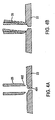
- the preferred method is to form a more resilient seal by forcing a spherically shaped device 402 into a matching concave surface 404.
- the convex spherical shape can be formed on the outer surface of the tube 25 and the concave surface in the module wall or vice versa.
- the concave depression could be conical in form as well as spherical.
- This method allows a seal that will accommodate a significant amount of misalignment if the tube 25 is continuously pressed into the concave surface 404 as, for instance, by the action of a spring or weight.
- Figure 4 illustrates this method and shows a significant misalignment accommodated while still maintaining a viable seal.
- Another aspect associated with assembling the ceramic modules into a useable oxygen generating system is how the modules 22 are mounted in the furnace 26 and how the electric power is applied to these modules 22.
- the means of supplying power to individual modules 22 and the means of mounting the modules 22 in the furnace are combined.
- FIG. 5 illustrates one method of combining mounting and power provisions.
- an L-shaped support bar 502 mounted above the modules provides physical support to restrain modules 22', 22", 22''', 22"" from moving.
- a second L-shaped support bar 504 is mounted below the modules 22', 22", 22"', 22"".
- Clips are formed from a material that retains strength at a high operating temperature such as Inconel and/or Monel.
- a clip is formed in a "U" shaped cross section of a suitable dimension to clamp tightly around the ends of the modules as depicted in Figure 5A .
- a multi-fingered U-clip similar to typical printed circuit board card-edge electrical connectors is preferred.
- the multi-fingered U-clip can more readily accommodate module 22 thickness variations along the clip's longitudinal axis.
- the clips 510, 512 are permanently attached to the support bars 502, 504 using a technique such as welding or brazing. Both the clip 510, 512 and support 502, 504 are then coated with a conductive material, such as silver, to minimize electrical and interfacial resistances.
- Power is provided to the system by applying a positive voltage to the end of one support bar 502, 504 and a negative voltage to the end of the other support bar 502, 504.
- the modules 22', 22", 22"', 22"" are provided power in a parallel-powered configuration. That is, the same voltage is applied to all modules 22', 22", 22"', 22"".
- a series-powered configuration is also possible. If the surface of the support bar 502, 504 is nonconductive, as a result of a coating, oxidation layer, or bulk material property, then a series-powered configuration is also possible. If the series configuration is desired, the clips are not electrically connected to the support bars.
- This configuration is illustrated in Figure 6 .
- "Z" clips 610, 612, 614 are each formed from a single piece of a metal that retains strength at the operating temperature, then coated with a conductive material such as silver.
- Each clip 610, 612, 614 is attached to the support bar 502 can be used at each end of the string to supply the positive and negative voltages to the modules 22.
- the clips may be electrically connected to the support bars.
- the support bars 502, 504 are coated with a conductive coating except in selected shaded regions 502', 502", 502"' and 504', 504", 504"' as illustrated in Figure 7 .
- the support bar can be segmented to provide electrical isolation in the designated areas shown in black. Also, by rotating every other module 180° the "z-strip" shown in Figure 7 can be eliminated.
- the manifold assembly 700 includes a manifold body 720 having a wide portion 725 which is positioned in the oven chamber 26. Extending outwardly from the oven is an outer portion 730. A plurality of manifold mounting clips 732, preferably made from inconel are fastened to a top surface 734 of the portion 725. As depicted, there are six manifold clips 732, although it should be understood that any number can be used.
- Two tubes 740, 742 are positioned within walls 750, 752.
- Walls 750, 752 extend the entire length of portion 730 and for the majority of the length portion 725.
- a gap is formed between tube 740, 742 and walls 750, 752 to provide a passageway.
- the mounting clip 732 extend inwardly into the oven chamber 726.
- the manifolds 700 can either be mounted horizontally or vertically. Ceramic oxygen generating modules 22 are each clipped into a pair of clips 732 as described below.
- a return passageway 780 is formed between walls 750, 752, tubes 740, 742 and the upper surface 734 of manifold body 720.
- the wider portion 730 of the assembly 700 where the mounting clip 732 are attached is inside the oven chamber 26 while the narrower portion 730 of the assembly 700 is outside the oven chamber 26.
- the manifold assembly operates as follows: cool fresh air flows through tubular elements 740, 742, picking up heat as the cool fresh air flows to the opposite end 782 (see Figure 8B ). At the end of 782, the fresh air makes a turn and flows into the outer distribution passages 760, 762. The hot fresh air then enters the oven chamber 26 through holes 320. Hot oxygen depleted air exits the oven chamber 26 through holes 770 into the volume 780 formed between the tubular elements 740, 742 and the distribution passages 760, 762.
- the hot depleted air passes over the tubular element 740, 742 giving up heat to the fresh air inside the tubular elements 740, 742 as the hot depleted air flows out of portion 730.
- the manifold assembly has the following functions and features: mechanical supporter of the ceramic modules 22, electrical connection to the ceramic modules 22, fresh air distribution and injection into the oven chamber 26, depleted air extraction from the oven chamber 26, heat exchange between the fresh and depleted air, and cooling of the mounting clip 732 and manifold assembly 700 due to heat exchange within.
- the mounting clip 732 is depicted in Figure 10 is a sheet metal part that has a flat mounting face 1100 and two rows of spring contacts 1110, 1120. Each of the contacts 1130 provides for secure mounting and electrical connection for each of the ceramic modules 22. Inconel or another high temperature alloyed is preferred as the material for the mounting clip.
- the assembly 700 will be somewhat cooler than the ceramic modules 22 and oven chamber 26 is a consequence of the heat exchange occurring within.
- the cooler temperature will provide for longer assembly life and/or less stringent metallic material requirements.
- the cooler temperature will also help ensure electrical connection integrity because of more stiffness in the mounting clip 732 material, less degradation of the conductive coating that is applied to the clips 732, and higher electrical conductivity of the metallic materials.
- the oxygen generating system described herein can also be used to provide a supply of pure oxygen from an air supply that contains chemical and/or biological contaminants. Because of the nature of the process used to generate oxygen and the temperature at which the system operates, chemical and/or biological contaminant are precluded from passing through the oxygen-generating modules 22 into the product plenum 34. In addition, because of the high operating temperature of the modules 22, the operating temperature is sufficient to kill most or all biological agents and decompose toxic compounds.
- the foregoing arrangement has many uses including, but not necessarily limited to, providing pure oxygen to processes which operate in a contaminated environment, for example, in chemical plants and pharmaceutical manufacturing operations, and may also be used to provide oxygen for human consumption in environments that have been intentionally contaminated as a result of chemical and/or biological warfare.
- one or more oxygen generators such as those described herein for the purpose of decontaminating air in a building or other environment that has been subject to intentional or unintentional chemical and/or biological contamination, for example, for an accidental biological release in a laboratory environment.
- the properties of the solid ceramic electrolyte enable the separation process to occur at a fundamentally higher level of selectivity than is possible using porous filtration methods, such as pressure-swing adsorption (PSA).
- PSD pressure-swing adsorption
- the solid electrolyte used in forming the ceramic modules 22 is formed as a dense ceramic member (defined as containing no open porosity).
- the crystal structure of the solid electrolyte contains oxygen ions, in addition to metal cat-ions. Examples of chemical formulas are Zr0 2 and Ce0 2 .
- the base compositions are altered by the substitution of a small percentage (typically 5%-20%) of the metal ions by another metal cation of a slightly different size and electrical charge. The result of the substitution is the creation of oxygen vacancies within the crystal structure of the ceramic material.
- the negatively charged oxygen ions present in the ceramic material are able to move in response an applied electric field.
- the oxygen ions move toward the positively charged surface by diffusing into crystal lattice sites that contain oxygen vacancies.
- the oxygen ions reach the positively charged surface, they recombine to form oxygen gas (0 2 ).
- the oxygen ions and the vacancies through which they diffuse in the Electrochemical Oxygen Generating System have a radius on the order of 1 Angstrom (10 -10 meters). This small size precludes the entry of any biological agent or other toxic compound.
- the crystal structure is adapted specifically to incorporate the size and electronic orbital structure of the oxygen ion. Occupancy of these sites by any ion other than oxygen would require a rearrangement of the crystal structure, which would require an amount of energy much greater than that encountered during the operation of this device.
- the ceramic electrolyte can be operated between 500 and 1000 degrees Celsius, which is sufficiently high to decompose most or all biological agents and toxic compounds.
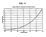
- the temperature dependence of oxygen output for Electrochemical Oxygen Generating System is illustrated in Figure 11 .
- the oxygen output of the oxygen generating system is directly proportional to the electrical current measured across the ceramic modules.
- the amount of current, I, generated is related to the voltage, V, and the electrical resistance, R, of the ceramic electrolyte by the following relationship known as Ohm's Law.
- I V / R
- the electrical resistance of the electrolyte decreases strongly with increasing temperature, resulting in a higher oxygen output when the voltage is held constant and the temperature is increased.
- the temperature dependence between 500 and 800 degrees Celsius is shown in Figure 11 .
Description
- This invention relates to devices for separating oxygen from more complex gasses such as air which contains oxygen, and delivering the separated-oxygen at an elevated pressure for use immediately, or for storage and use later. More particularly, the invention relates to solid state electrochemical devices for separating oxygen from more complex gasses to produce the desired oxygen and delivering the oxygen at elevated pressures up to and exceeding 137.9 Bar (2000 psig).
- It is well known, and has been demonstrated, that oxygen can be removed from more complex gasses, such as air, by an electrochemical process of ionizing the oxygen molecules, transporting the oxygen ions through a solid electrolyte and reforming the oxygen molecules on an opposite electrolyte surface. An electrical potential is applied to a suitable catalyzing electrode coating applied to the surface of the electrolyte which is porous to oxygen molecules and which acts to disassociate oxygen molecules into oxygen ions at its interface with the electrolyte. The oxygen ions are transported through the electrolyte to the opposite surface, which is also coated with a catalyzing electrode and electrically charged with the opposite electrical potential that removes the excess electrons from the oxygen ions, and oxygen molecules are reformed. However, current oxygen generating systems are unable to deliver high pressure oxygen above 82.74 Bar (1200 psi). Examples of known oxygen generating systems are disclosed in
WO-A-9948595 US-A-5186793 .WO-A-9948595 US-A-5186793 discloses an oxygen concentration system for producing oxygen from air comprising an electrochemical oxygen concentrator mounted within an inner housing having the form of an annulus. Overall, a need exists in the art for a system and a method which provides a high pressure oxygen. Another need exists in the art for an oxygen generating system which can use contaminated air which is contaminated, for example, with biological agents and/or other toxic substances. - It is, therefore, an object of the present invention to provide an electrochemical oxygen generating system which can provide high-pressure oxygen.
- It is another object of the present invention to provide an electrochemical oxygen generating system which can provide oxygen at pressures up to 137.9 Bar (2000 psi).
- It is another object of the present invention to provide a heat exchange system which can regulate the temperature of oxygen generating modules during oxygen production.
- Yet another object of the present invention is to provide a control system for controlling oven chamber temperatures.
- Another object of the present invention is to provide a unique mounting and electrical interconnection structure for supporting the oxygen generating modules and provide electrical power thereto.
- Another object of the present invention is to provide an oxygen generating system capable of using contaminated air and capable of filtering the contaminated air and providing breathable high purity oxygen gas.
- Still another object of the present invention is to provide an oxygen generating system capable of using air contaminated with biological agents and/or
other toxic substances and capable of generating breathable high purity oxygen gas. - Still another object of the present invention is to provide a method of sealing a ceramic tube to a ceramic module to allow each to thermally expand and contract without cracking.
- These and other objects of the present invention are achieved by an electrochemical oxygen generating system including an oven chamber having a fresh air inlet and a depleted air outlet, at least one ceramic oxygen generating module located in the oven chamber and having an oxygen outlet, a heater mounted in the oven chamber, a heat exchanger positioned between the fresh air inlet and the oven chamber, a controller for providing electrical power to the at least one ceramic oxygen generating module and for controlling the heater and a plurality of adjustable dampers being located between said fresh air inlet and said oven chamber.
- The proposed invention is suitable for, but is not limited to, the delivery of high purity oxygen for many medical, semiconductor and industrial applications as well as the filtration of chemical and biological agents in civil and military environments.
- Yet another object of the present invention is to provide an electrochemical oxygen generating system capable of utilizing an air supply that contains chemical and/or biological contaminants including an oven chamber having an air inlet from the air supply and a depleted air outlet, at least one ceramic oxygen generating module located in the oven chamber and having an oxygen outlet, a heater mounted in the oven chamber, a heat exchanger positioned between the fresh air inlet and the oven chamber, and a controller for providing electrical power to the at least one ceramic oxygen generating module and for controlling the heater, wherein oxygen gas provided to the oxygen outlet is free of the chemical and/or biological contaminants.
- Still other objects and advantages of the present invention will become readily apparent to those skilled in the art from the following detailed description, wherein the preferred embodiments of the invention are shown and described,
simply by way of illustration of the best mode contemplated of carrying out the invention. As will be realized, the invention is capable of other and different embodiments, and its several details are capable of modifications in various obvious respects, all without departing from the invention. Accordingly, the drawings and description thereof are to be regarded as illustrative in nature, and not as restrictive. - The present invention is illustrated by way of example, and not by limitation, in the figures of the accompanying drawings, wherein elements having the same reference numeral designations represent like elements throughout and wherein:
-
Figure 1 depicts a schematic of a completeoxygen generating system 10 utilizing an electrochemical-oxygen generator in the form of a modular ceramic oxygen generator; -
Figure 2 is a schematic diagram depicting a cross-section of the ceramic oxygen generating system depicting the oven, insulation, modules, heaters, planar counter-flow heat exchanges, air-flow dampers and fan; -
Figure 3 is another schematic diagram similar toFigure 2 , depicting a second heat exchanger embodiment; -
Figure 4 depicts a pneumatic interface using a concave depression; -
Figure 5 depicts an arrangement for combining mounting and power provisions taken along lines 5-5 inFigure 2 ; -
Figure 5A is a partial cross-sectional view taken alonglines 5A-5A inFigure 5 ; -
Figure 6 depicts a mounting arrangement using "Z" clips; -
Figure 7 depicts an alternative "Z" clip arrangement in which the support bar is segmented to provide electrical isolation; and -
Figure 8A is a side elevational view of an integrated air distribution manifold and mounting clip assembly; -
Figure 8B is a cross-sectional view taken throughlines 8B-8B inFigure 8A ; -
Figure 8C is a top plan view of the integrated air distribution manifold; -
Figure 8D is an end view of the integrated air distribution manifold; -
Figure 8E is a cross-sectional view taken throughlines 8D-8D inFigure 8C ; -
Figure 8F is a bottom plan view of the integrated air distribution manifold; -
Figure 9 is a perspective view illustrating the use of the air distribution manifold ofFigures 8A-8F ; -
Figure 10 is a perspective view of the mounting clip used in the present invention; and -
Figure 11 is a graph illustrating the temperature dependence of oxygen output for the electrochemical oxygen generating system according to the present invention. -
U.S. Patent No. 5,985,113 (publication numberUS000005985113A U.S. Patent No. 5,871,624 (publication numberUS000005871624A 09/418,831 US000006194335B1 -
Figure 1 illustrates a schematic of a complete oxygen generatingsystem 10 utilizing an electrochemical-oxygen generator in the form of a modular ceramic oxygen generator. This schematic depicts a power supply andcontroller 20 that supplies electrical power to anoven heater 24 to raise the temperature within the operating range of an oxygen-generating module assembly 22. The oxygen-generatingmodule 22 assembly can include or more oxygen-generating modules such as those disclosed inU.S. Patent No. 5,871,624 (publication numberUS000005871624A 09/010,828 US000005985113A - The temperature range in an
oven chamber 26 may be about 500 to 800 degrees Celsius, depending on the materials used to construct the oxygen-generating module assembly 22. The oxygen-generatingmodules 22 are positioned in theoven chamber 26. After theoven chamber 26 reaches the minimum preferred operating temperature, as detected by at leastthermocouple 28 mounted in theoven chamber 26, thecontroller 20 begins to apply electrical power to afan motor 30 to deliver oxygen-laden air through acounter-flow heat exchanger 32 into theoven 26 chamber to amodule assembly 21 including at least onemodule 22. Thecontroller 20 also delivers electrical power to themodules 22, and oxygen is electrochemically generated, as taught inU.S. Patent No. 5,871,624 (publication numberUS000005871624A 09/010,828 US000005985113A modules 22 and oxygen is generated, electrical resistance within themodules 22 generates additional heat. To compensate for this additional heat, thecontroller 20 reduces power to theoven heater 24, to maintain the desired nominal operating temperature in theoven chamber 26. The oxygen being generated is delivered to aproduct plenum 34, which acts as a temporary oxygen storage vessel. The oxygen is delivered from theproduct plenum 34 to a low-pressure regulator 36,final filter 38,check valve 40,flow meter 42, and lastly a user-adjustable valve 44 for immediate use, for example, by a patient. - Oxygen may also be delivered to a high-pressure connection that allows
connection 50 of a removable portableoxygen storage cylinder 52. Theportable cylinder 52 is filled automatically and can be used later. Thecontroller 20 applies appropriate electrical power to themodules 22 to generate oxygen at elevated pressures until a high-pressure switch 54 detects a pressure over about 124.1 Bar (1800 psig). Upon exceeding 124.1 Bar (1800 psig), thecontroller 20 reduces power to themodules 22 until pressure at the high-pressure switch 54 falls below 124.1 Bar (1800 psig). Thecontroller 20 also electrically monitors the low-pressure switch 58. Thisswitch 54 enables regulation of the pressure delivered to theproduct plenum 34 and high-pressure connector 50 to a nominal pressure of about 124.1 Bar (1800 psig). A high-pressure relief valve 56 vents excess pressure above about 137.9 Bar (2000 psig), in the event of a malfunction of thecontroller 20 to limit the nominal pressure to less than 137.9 Bar (2000 psig), and to relieve excessive temperature-related pressure increases. It should be understood that the maximum normal operating pressure is approximately 124,1 Bar (1800 psig). Thecontroller 20 also electrically monitors the high-pressure switch 54. If the operating pressure is below the minimum operating pressure after a given period of time, then thecontroller 20 activates a warning light and audible alarm (not shown). -
Figure 2 illustrates a cross-section of the ceramic oxygen generating system depicting theoven 26,insulation 200, oxygen-generatingmodule assemblies 22,heaters 24, planarcounter-flow heat exchangers 32, air-flow dampers 202, andfan 30. The counter-flow heat exchanger is a very effective, simple, low-cost design approach. As depicted inFigure 2 , fouroxygen generating modules 22', 22", 22''', 22"" form the oxygen-generatingassembly 21 although any number of modules can be used. The oxygen-generatingmodules 22', 22", 22"', 22"" are manifolded together bytubes 23', 23", 23"'. Anoutlet tube 25 passes through thewall 210 to provide high pressure oxygen to theproduct plenum 34 and thehigh pressure connection 50. - Cool fresh air is heated before the air enters the inner oven, and the hot air is cooled before it exits the
oven 26; thereby, conserving energy. In a planar counter-flow configuration illustrated inFigure 2 , thefan 30 introduces cool, oxygen-laden air into thechannels inner walls oven insulation 200 and theinner surfaces inner oven 26 on the other side of the heat exchanger wall. The incoming air is also partially heated by an outer surface of thewalls oven insulation 200, followed by an inner surface of thewalls oven insulation 200, after a 180° turn mid-way into the inner oven.Channels fan 30 from left to right and then reverse and flow from right to left. - Electrical resistance is inherent to all electrochemical oxygen generating systems, because these systems generate oxygen with the flow of electrical current. The electrochemical
oxygen generating modules 22 generate heat as well as oxygen. Toomuch oven insulation 200 and very efficient heat exchangers could result in runaway oven temperatures. One method of temperature control is to ensure that some amount of heater activation is always used to maintain the normal operating temperature, after the initial startup period of time. Another method is to adjust thefan 30 speed to cause additional air to be circulated through theoven 26 carrying away the excess heat. Thecontroller 20 monitors the temperature in theinner oven 26 using one or more strategically placed thermocouples 28 (not shown inFigure 2 ) to ensure that the oven temperatures are normal. Thecontroller 20 uses this information to adjust either theheater 24 voltage orfan 30 speed to control the temperature of theinner oven 26. - As depicted in
Figure 2 , sixair dampers 202 are used in the embodiment depicted inFigure 2 . Three dampers are each mounted towalls dampers 202 being positioned betweenmodules 22 and opposite each other. Theair dampers 202 shown allow some oxygen-laden air to enter the module chamber orinner oven 26 before completing the entire heat exchanger flow-path to the inner oven. If all oxygen-laden air were forced to traverse the entire heat exchanger flow-path, a higher temperature gradient would occur across the series ofmodules 22 in the oven. The air would be progressively heated as it passes over eachmodule 22. Allowing some air to enter near thelatter modules 22"', 22"" provides a more uniform temperature across the modules 22'-22"" and preventsmodules 22"', 22"" from possibly over-heating. Thesedampers 202 are adjustable and can be manually adjusted during the assembly of thesystem 10 and during an initial start up test process after completion of the manufacturing and assembly process of thesystem 10. Thesedampers 202 include damper flaps 204 which are mounted to a suitable cylindrical rod (not shown) that extends through the inner oven insulation and support structure to outside theinner oven 26. The external ends of the damper rods can be rotated and secured in the preferred orientation during the assembly process. Alternately, the dampers could be adjusted automatically by thecontroller 20, based upon theinner oven 26 temperatures measured by thethermocouples 28. Several types of electromechanical damper actuators are available that could be used. -
Figure 3 depicts another type of heat exchanger embodiment. This is another approach comparable to the planar heat exchanger with flow control dampers described above with respect toFigure 2 . A tubular heat exchanger approach utilizes multiplecylindrical tubes inner oven 26, and returns to the opposite end of the oven on the inside of the inner insulation. The cool oxygen-laden air is forced into thetubes fan 30 and delivered to theinner oven 26 at the same end of the oven. The hot oxygen-depleted air flows in the opposite direction around the outside of thetubes holes 320 at strategic points (typically betweenmodules 22', 22"; 22", 22"'; and 22"', 22"") along the return path in the inner oven, or some of the tubes end at strategic points along the return path in theinner oven 26. This allows some air to enter the chamber prior to traversing the complete length of thetubes - As depicted in
Figure 3 ,dampers tubes fan 30. Some of the tubes that do not have holes or do not end before traversing the complete pathway into theinner oven 26 at the fan-end also do not have dampers. The remaining tubes, that do have holes or do end before traversing the complete pathway into the inner oven at the fan-end, also do have dampers. The dampers are located at the open end of the appropriate tubes on the fan-side of a tube-plate that secures the tubes in place. The dampers can be positioned across the open-ends of the tubes to occlude them, as required to regulate the temperature of each zone within the inner oven. Thedampers controller 20 as described earlier. - Another method for controlling the temperature of the ceramic generator or the rate of oxygen production is to reduce the quantity of feed air supplied to the generator, or to reduce the quantity of oxygen in the feed air. As previously explained, there is an equivalence between the rate of oxygen production and the current flow through the ceramic generator. The electrical current flow is proportional to the voltage applied to the generator minus the Nernst-Einstein voltage. The Nernst-Einstein voltage is proportional to the difference in the oxygen partial pressures at the input and output of the ceramic generator. Therefore, as the input oxygen partial-pressure decreases or as the output oxygen partial pressure increases, or both, the current flow and thus the oxygen flow is decreased. In practice the input oxygen partial pressure can be reduced by use of the dampers previously described as well as other means such as reducing
fan 30 speed. As the oxygen flow and the current flow through the ceramic generator are reduced, the power dissipation in the generator is reduced thereby reducing the self-heating within the module resulting in a lower generator temperature. - In all of the described embodiments, the
oxygen delivery tubes 23', 23", 23"' and 25 of theindividual modules 22 must either extend outside the heated section of the furnace or be internally joined and the resultingtube 25 extended outside the furnace. One method of extending individual tubes outside the furnace orinner oven 26 is to use aceramic tube 25 sealed into a matched hole in the module 22'. The use of a ceramic tube minimizes stresses on the tube-to-module interface caused by differing coefficients of thermal expansion. However, this method presents a problem in that the tube, module, and seal are all composed of brittle materials that cannot sustain any significant displacement without breaking. It is difficult to prevent the application of bending moments on the tubes using this approach. The preferred method is to form a more resilient seal by forcing a sphericallyshaped device 402 into a matchingconcave surface 404. The convex spherical shape can be formed on the outer surface of thetube 25 and the concave surface in the module wall or vice versa. Also, the concave depression could be conical in form as well as spherical. This method allows a seal that will accommodate a significant amount of misalignment if thetube 25 is continuously pressed into theconcave surface 404 as, for instance, by the action of a spring or weight.Figure 4 illustrates this method and shows a significant misalignment accommodated while still maintaining a viable seal. - Another aspect associated with assembling the ceramic modules into a useable oxygen generating system is how the
modules 22 are mounted in thefurnace 26 and how the electric power is applied to thesemodules 22. In the present invention, the means of supplying power toindividual modules 22 and the means of mounting themodules 22 in the furnace are combined. -
Figure 5 illustrates one method of combining mounting and power provisions. As illustrated, an L-shapedsupport bar 502 mounted above the modules provides physical support to restrainmodules 22', 22", 22''', 22"" from moving. A second L-shapedsupport bar 504 is mounted below themodules 22', 22", 22"', 22"". Clips are formed from a material that retains strength at a high operating temperature such as Inconel and/or Monel. A clip is formed in a "U" shaped cross section of a suitable dimension to clamp tightly around the ends of the modules as depicted inFigure 5A . A multi-fingered U-clip similar to typical printed circuit board card-edge electrical connectors is preferred. The multi-fingered U-clip can more readily accommodatemodule 22 thickness variations along the clip's longitudinal axis. Theclips clip support support bar other support bar Figure 5 , themodules 22', 22", 22"', 22"" are provided power in a parallel-powered configuration. That is, the same voltage is applied to allmodules 22', 22", 22"', 22"". - If the surface of the
support bar Figure 6 . In this configuration, "Z" clips 610, 612, 614 are each formed from a single piece of a metal that retains strength at the operating temperature, then coated with a conductive material such as silver. Eachclip support bar 502 can be used at each end of the string to supply the positive and negative voltages to themodules 22. In another embodiment, the clips may be electrically connected to the support bars. In this case, the support bars 502, 504 are coated with a conductive coating except in selectedshaded regions 502', 502", 502"' and 504', 504", 504"' as illustrated inFigure 7 . Alternatively, the support bar can be segmented to provide electrical isolation in the designated areas shown in black. Also, by rotating every other module 180° the "z-strip" shown inFigure 7 can be eliminated. - Referring now to
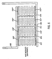
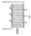
Figures 8A-8F , an integrated air distribution manifold and mounting clip system is depicted. This manifold is primarily usable for the schematic illustrations depicted inFigures 2 and3 . As depicted inFigure 8A , themanifold assembly 700 includes amanifold body 720 having awide portion 725 which is positioned in theoven chamber 26. Extending outwardly from the oven is anouter portion 730. A plurality ofmanifold mounting clips 732, preferably made from inconel are fastened to atop surface 734 of theportion 725. As depicted, there are sixmanifold clips 732, although it should be understood that any number can be used. Twotubes 740, 742 (seeFigure 8C ) are positioned withinwalls Walls portion 730 and for the majority of thelength portion 725. A gap is formed betweentube walls Figure 8 , there areouter passageways walls Figure 8C , there are a plurality of holes worn between mountingclips 732 in theportion 730. The holes are 770. As depicted inFigure 8D , the mountingclip 732 extend inwardly into the oven chamber 726. - It should be noted that two manifold assemblies are used on opposite ends of the
ceramic modules 22. Themanifolds 700 can either be mounted horizontally or vertically. Ceramicoxygen generating modules 22 are each clipped into a pair ofclips 732 as described below. - As depicted in
Figure 8E , areturn passageway 780 is formed betweenwalls tubes upper surface 734 ofmanifold body 720. - The
wider portion 730 of theassembly 700 where the mountingclip 732 are attached is inside theoven chamber 26 while thenarrower portion 730 of theassembly 700 is outside theoven chamber 26. The manifold assembly operates as follows: cool fresh air flows throughtubular elements Figure 8B ). At the end of 782, the fresh air makes a turn and flows into theouter distribution passages oven chamber 26 throughholes 320. Hot oxygen depleted air exits theoven chamber 26 throughholes 770 into thevolume 780 formed between thetubular elements distribution passages tubular element tubular elements portion 730. Advantageously the manifold assembly has the following functions and features: mechanical supporter of theceramic modules 22, electrical connection to theceramic modules 22, fresh air distribution and injection into theoven chamber 26, depleted air extraction from theoven chamber 26, heat exchange between the fresh and depleted air, and cooling of the mountingclip 732 andmanifold assembly 700 due to heat exchange within. - The mounting
clip 732 is depicted inFigure 10 is a sheet metal part that has aflat mounting face 1100 and two rows ofspring contacts 1110, 1120. Each of thecontacts 1130 provides for secure mounting and electrical connection for each of theceramic modules 22. Inconel or another high temperature alloyed is preferred as the material for the mounting clip. - The
assembly 700 will be somewhat cooler than theceramic modules 22 andoven chamber 26 is a consequence of the heat exchange occurring within. The cooler temperature will provide for longer assembly life and/or less stringent metallic material requirements. The cooler temperature will also help ensure electrical connection integrity because of more stiffness in the mountingclip 732 material, less degradation of the conductive coating that is applied to theclips 732, and higher electrical conductivity of the metallic materials. - The oxygen generating system described herein can also be used to provide a supply of pure oxygen from an air supply that contains chemical and/or biological contaminants. Because of the nature of the process used to generate oxygen and the temperature at which the system operates, chemical and/or biological contaminant are precluded from passing through the oxygen-generating
modules 22 into theproduct plenum 34. In addition, because of the high operating temperature of themodules 22, the operating temperature is sufficient to kill most or all biological agents and decompose toxic compounds. The foregoing arrangement has many uses including, but not necessarily limited to, providing pure oxygen to processes which operate in a contaminated environment, for example, in chemical plants and pharmaceutical manufacturing operations, and may also be used to provide oxygen for human consumption in environments that have been intentionally contaminated as a result of chemical and/or biological warfare. Furthermore, it is possible to utilize one or more oxygen generators such as those described herein for the purpose of decontaminating air in a building or other environment that has been subject to intentional or unintentional chemical and/or biological contamination, for example, for an accidental biological release in a laboratory environment. - The properties of the solid ceramic electrolyte enable the separation process to occur at a fundamentally higher level of selectivity than is possible using porous filtration methods, such as pressure-swing adsorption (PSA). The solid electrolyte used in forming the
ceramic modules 22 is formed as a dense ceramic member (defined as containing no open porosity). The crystal structure of the solid electrolyte contains oxygen ions, in addition to metal cat-ions. Examples of chemical formulas are Zr02 and Ce02. The base compositions are altered by the substitution of a small percentage (typically 5%-20%) of the metal ions by another metal cation of a slightly different size and electrical charge. The result of the substitution is the creation of oxygen vacancies within the crystal structure of the ceramic material. At elevated temperatures (above 500 degrees C for known ceramic electrolytes) the negatively charged oxygen ions present in the ceramic material are able to move in response an applied electric field. The oxygen ions move toward the positively charged surface by diffusing into crystal lattice sites that contain oxygen vacancies. When the oxygen ions reach the positively charged surface, they recombine to form oxygen gas (02). - The oxygen ions and the vacancies through which they diffuse in the Electrochemical Oxygen Generating System have a radius on the order of 1 Angstrom (10-10 meters). This small size precludes the entry of any biological agent or other toxic compound. Additionally, the crystal structure is adapted specifically to incorporate the size and electronic orbital structure of the oxygen ion. Occupancy of these sites by any ion other than oxygen would require a rearrangement of the crystal structure, which would require an amount of energy much greater than that encountered during the operation of this device. The ceramic electrolyte can be operated between 500 and 1000 degrees Celsius, which is sufficiently high to decompose most or all biological agents and toxic compounds.
- The temperature dependence of oxygen output for Electrochemical Oxygen Generating System is illustrated in
Figure 11 . The oxygen output of the oxygen generating system is directly proportional to the electrical current measured across the ceramic modules. When a constant electrical voltage is applied across a module, the amount of current, I, generated is related to the voltage, V, and the electrical resistance, R, of the ceramic electrolyte by the following relationship known as Ohm's Law.
- The electrical resistance of the electrolyte decreases strongly with increasing temperature, resulting in a higher oxygen output when the voltage is held constant and the temperature is increased. The temperature dependence between 500 and 800 degrees Celsius is shown in
Figure 11 . - It will be readily seen by one of ordinary skill in the art that the present invention fulfills all of the objects set forth above. After reading the foregoing specification, one of ordinary skill will be able to affect various changes, substitutions of equivalents and various other aspects of the invention as broadly disclosed herein. It is therefore intended that the protection granted hereon be limited only by the definition contained in the appended claims.
Claims (15)
- An electrochemical oxygen generating system, comprising:an oven chamber having a fresh air inlet and a depleted air outlet; at least one ceramic oxygen generating module located in said oven chamber and having an oxygen outlet;a heater mounted in said oven chamber;a heat exchanger positioned between said fresh air inlet and said oven chamber; anda controller for providing electrical power to said at least one ceramic oxygen generating module and for controlling said heatercharacterised in that
the electrochemical oxygen generating system comprises a plurality of adjustable dampers located between said fresh air inlet and said oven chamber. - The electrochemical oxygen generating system of claim 1, wherein said heat exchanger comprises at least one hole for allowing some of the fresh air to enter the oven chamber.
- The electrochemical oxygen generating system of claim 1, further comprising a thermocouple mounted in said oven chamber, said thermocouple sending a signal to said controller indicative of a temperature in said oven chamber.
- The electrochemical oxygen generating system of claim 1, further comprising at least one further damper connected to said heat exchanger and controlled by said controller for allowing some of the fresh air to be redirected into said oven chamber.
- The electrochemical oxygen generating system of claim 1, further comprising a fan located between said fresh air inlet and said oven chamber.
- The electrochemical oxygen generating system of claim 1, comprising a plurality of ceramic oxygen generating modules manifolded together.
- The electrochemical oxygen generating system of claim 1, wherein said electrochemical oxygen generating system can produce oxygen at said oxygen outlet at pressures up to 137.9 Bar.
- The electrochemical oxygen generating system of claim 1, wherein said controller controls fan speed to regulate oven chamber temperature.
- The electrochemical oxygen generating system of claim 1, wherein said heat exchanger provides a 180° path for fresh air entering said oven chamber and said depleted air has been heated in said oven chamber and is used to preheat said fresh air in said heat exchanger.
- The electrochemical oxygen generating system of claim 1, further comprising two mounting brackets and at least two ceramic oxygen generating modules.
- The electrochemical oxygen generating system of claim 1, wherein said heat exchanger is a counter-flow heat exchanger.
- The electrochemical oxygen generating system of claim 9, wherein said two mounting brackets provide electrical power to said at least two ceramic oxygen generating modules in one of series and parallel heat.
- The electrochemical oxygen generating system of claim 1, wherein said heat exchanger includes a manifold assembly and a plurality of mounting clips each for mounting said at least one ceramic oxygen generating module and for providing an electrical connection thereto.
- The electrochemical oxygen generating system of claim 12, wherein said manifold assembly includes a plurality of tubes located in a manifold body, wherein said plurality of tubes provides a fresh air inlet, at least one distribution channel formed outside said plurality of tubes, and return passageway for carrying oxygen depleted air.
- The electrochemical oxygen generating system according to anyone of the preceding claims, wherein the system is capable of utilizing an air supply that contains chemical and/or biological contaminants, and wherein the system provides oxygen gas to said oxygen outlet being free of said chemical and/or biological contaminants.
Applications Claiming Priority (4)
| Application Number | Priority Date | Filing Date | Title |
|---|---|---|---|
| US137219 | 1987-12-23 | ||
| US13721999P | 1999-06-01 | 1999-06-01 | |
| US09/573,891 US6352624B1 (en) | 1999-06-01 | 2000-05-19 | Electrochemical oxygen generating system |
| US573891 | 2000-05-19 |
Publications (2)
| Publication Number | Publication Date |
|---|---|
| EP1057517A1 EP1057517A1 (en) | 2000-12-06 |
| EP1057517B1 true EP1057517B1 (en) | 2009-07-22 |
Family
ID=26835041
Family Applications (1)
| Application Number | Title | Priority Date | Filing Date |
|---|---|---|---|
| EP00111668A Expired - Lifetime EP1057517B1 (en) | 1999-06-01 | 2000-05-31 | Electrochemical oxygen generating system |
Country Status (7)
| Country | Link |
|---|---|
| US (1) | US6352624B1 (en) |
| EP (1) | EP1057517B1 (en) |
| JP (2) | JP5153973B2 (en) |
| KR (1) | KR100721785B1 (en) |
| CA (1) | CA2310211C (en) |
| DE (1) | DE60042578D1 (en) |
| NO (1) | NO20002810L (en) |
Families Citing this family (46)
| Publication number | Priority date | Publication date | Assignee | Title |
|---|---|---|---|---|
| US6383350B1 (en) * | 2000-07-26 | 2002-05-07 | Northrop Grumman Corporation | Thin film modular electrochemical apparatus and method of manufacture therefor |
| DE10053546A1 (en) * | 2000-10-27 | 2002-05-02 | Angewandte Technik Mbh Greifsw | Portable electrochemical oxygen generator |
| KR20020071099A (en) * | 2001-03-03 | 2002-09-12 | (주)에너펙텍 | A hydrogen and oxygen generator |
| EP1472022A4 (en) * | 2002-01-07 | 2005-03-09 | Carleton Life Support Sys Inc | Method for attaching tubing |
| KR100462155B1 (en) * | 2002-10-23 | 2004-12-23 | (주)바이오텔 | Oxygen producing device for dual application either in vehicles or indoor |
| US20040065541A1 (en) * | 2002-08-27 | 2004-04-08 | Litton Systems, Inc. | Stepped voltage controller for ceramic oxygen generating systems |
| US6783646B2 (en) * | 2002-08-28 | 2004-08-31 | Carleton Life Support Systems, Inc. | Modular ceramic oxygen system |
| KR20040036004A (en) * | 2002-10-23 | 2004-04-30 | 주식회사 이앤이 | brown gas flow regulator |
| US6905581B2 (en) * | 2002-10-31 | 2005-06-14 | Carleton Life Support Systems, Inc. | Oxygen permeable electrode system |
| JP2006021955A (en) * | 2004-07-08 | 2006-01-26 | Matsushita Electric Ind Co Ltd | Oxygen concentrator |
| US7694674B2 (en) * | 2004-09-21 | 2010-04-13 | Carleton Life Support Systems, Inc. | Oxygen generator with storage and conservation modes |
| US7501100B2 (en) * | 2004-11-08 | 2009-03-10 | Praxair Technology, Inc. | Filter system for electrochemical air separation device |
| US7396442B2 (en) | 2005-02-08 | 2008-07-08 | Carleton Life Support Systems, Inc. | Electrochemical oxygen generator module assembly |
| KR100684685B1 (en) | 2005-03-17 | 2007-02-20 | 김춘식 | Occurrence apparatus for hydrogen oxygen mixing gas |
| JP5092222B2 (en) * | 2005-10-03 | 2012-12-05 | パナソニック株式会社 | Oxygen and ozone generator |
| ATE414039T1 (en) * | 2005-11-24 | 2008-11-15 | Air Liquide | METHOD FOR PRODUCING OXYGEN FROM AIR, IN PARTICULAR USING AN ELECTROCHEMICAL CELL WITH A CERAMIC MEMBRANE AND WITH A CONTROL DEVICE FOR THE CONTINUOUS PRODUCTION OF OXYGEN |
| US7309847B2 (en) * | 2006-01-12 | 2007-12-18 | Carleton Life Support Systems, Inc. | Ceramic oxygen generating oven |
| JP5329036B2 (en) * | 2006-12-19 | 2013-10-30 | キヤノンマシナリー株式会社 | Oxygen pump |
| US20090252995A1 (en) * | 2008-04-03 | 2009-10-08 | Eickhoff Steven J | Fuel cell with oxygen transport membrane |
| US8323378B2 (en) * | 2010-04-28 | 2012-12-04 | Praxair Technology, Inc. | Oxygen supply method and apparatus |
| US9561476B2 (en) | 2010-12-15 | 2017-02-07 | Praxair Technology, Inc. | Catalyst containing oxygen transport membrane |
| US8409323B2 (en) | 2011-04-07 | 2013-04-02 | Praxair Technology, Inc. | Control method and apparatus |
| WO2013089895A1 (en) | 2011-12-15 | 2013-06-20 | Praxair Technology, Inc. | Composite oxygen transport membrane |
| US9486735B2 (en) | 2011-12-15 | 2016-11-08 | Praxair Technology, Inc. | Composite oxygen transport membrane |
| US9550570B2 (en) * | 2012-05-25 | 2017-01-24 | B/E Aerospace, Inc. | On-board generation of oxygen for aircraft passengers |
| US9120571B2 (en) | 2012-05-25 | 2015-09-01 | B/E Aerospace, Inc. | Hybrid on-board generation of oxygen for aircraft passengers |
| WO2014100376A1 (en) | 2012-12-19 | 2014-06-26 | Praxair Technology, Inc. | Method for sealing an oxygen transport membrane assembly |
| US9453644B2 (en) | 2012-12-28 | 2016-09-27 | Praxair Technology, Inc. | Oxygen transport membrane based advanced power cycle with low pressure synthesis gas slip stream |
| JP6229709B2 (en) | 2013-02-28 | 2017-11-15 | 日産自動車株式会社 | Positive electrode active material, positive electrode material, positive electrode and non-aqueous electrolyte secondary battery |
| US9296671B2 (en) | 2013-04-26 | 2016-03-29 | Praxair Technology, Inc. | Method and system for producing methanol using an integrated oxygen transport membrane based reforming system |
| US9611144B2 (en) | 2013-04-26 | 2017-04-04 | Praxair Technology, Inc. | Method and system for producing a synthesis gas in an oxygen transport membrane based reforming system that is free of metal dusting corrosion |
| US9938145B2 (en) | 2013-04-26 | 2018-04-10 | Praxair Technology, Inc. | Method and system for adjusting synthesis gas module in an oxygen transport membrane based reforming system |
| US9212113B2 (en) | 2013-04-26 | 2015-12-15 | Praxair Technology, Inc. | Method and system for producing a synthesis gas using an oxygen transport membrane based reforming system with secondary reforming and auxiliary heat source |
| MX2016004495A (en) | 2013-10-07 | 2016-06-16 | Praxair Technology Inc | Ceramic oxygen transport membrane array reforming reactor. |
| US9573094B2 (en) | 2013-10-08 | 2017-02-21 | Praxair Technology, Inc. | System and method for temperature control in an oxygen transport membrane based reactor |
| CN105764842B (en) | 2013-12-02 | 2018-06-05 | 普莱克斯技术有限公司 | Use the method and system of the production hydrogen of the reforming system based on oxygen transport film with two process transform |
| US9562472B2 (en) | 2014-02-12 | 2017-02-07 | Praxair Technology, Inc. | Oxygen transport membrane reactor based method and system for generating electric power |
| WO2015160609A1 (en) | 2014-04-16 | 2015-10-22 | Praxair Technology, Inc. | Method and system for oxygen transport membrane enhanced integrated gasifier combined cycle (igcc) |
| US9797054B2 (en) | 2014-07-09 | 2017-10-24 | Carleton Life Support Systems Inc. | Pressure driven ceramic oxygen generation system with integrated manifold and tubes |
| WO2016057164A1 (en) | 2014-10-07 | 2016-04-14 | Praxair Technology, Inc | Composite oxygen ion transport membrane |
| US10441922B2 (en) | 2015-06-29 | 2019-10-15 | Praxair Technology, Inc. | Dual function composite oxygen transport membrane |
| US10118823B2 (en) | 2015-12-15 | 2018-11-06 | Praxair Technology, Inc. | Method of thermally-stabilizing an oxygen transport membrane-based reforming system |
| US9938146B2 (en) | 2015-12-28 | 2018-04-10 | Praxair Technology, Inc. | High aspect ratio catalytic reactor and catalyst inserts therefor |
| CN109070014A (en) | 2016-04-01 | 2018-12-21 | 普莱克斯技术有限公司 | Oxygen transport membrane containing catalyst |
| EP3797085A1 (en) | 2018-05-21 | 2021-03-31 | Praxair Technology, Inc. | Otm syngas panel with gas heated reformer |
| CN114314516B (en) * | 2022-02-22 | 2022-07-22 | 中山清匠电器科技有限公司 | Dispersion formula oxygenerator of intelligence control by temperature change |
Family Cites Families (11)
| Publication number | Priority date | Publication date | Assignee | Title |
|---|---|---|---|---|
| US4713152A (en) * | 1987-03-09 | 1987-12-15 | Vsm Associates, Inc. | Method and system for the removal of oxides of nitrogen and sulfur from combustion processes |
| US5332483A (en) | 1990-07-06 | 1994-07-26 | Igr Enterprises, Inc. | Gas separation system |
| US5205990A (en) * | 1990-08-02 | 1993-04-27 | Lawless William N | Oxygen generator having honeycomb structure |
| US5186793A (en) | 1990-12-31 | 1993-02-16 | Invacare Corporation | Oxygen concentrator utilizing electrochemical cell |
| JPH06170151A (en) * | 1990-12-31 | 1994-06-21 | Invacare Corp | Oxygen concentrating device using electrochemical cell |
| US5169506A (en) * | 1990-12-31 | 1992-12-08 | Invacare Corporation | Oxygen concentration system utilizing pressurized air |
| US5441610A (en) * | 1992-02-28 | 1995-08-15 | Renlund; Gary M. | Oxygen supply and removal method and apparatus |
| US5985113A (en) | 1995-08-24 | 1999-11-16 | Litton Systems, Inc. | Modular ceramic electrochemical apparatus and method of manufacture therefor |
| CA2182069C (en) | 1995-08-24 | 2002-04-09 | Victor P. Crome | Modular ceramic oxygen generator |
| US6117210A (en) * | 1997-04-29 | 2000-09-12 | Praxair Technology, Inc. | Solid electrolyte systems for producing controlled purity oxygen |
| US6033457A (en) * | 1998-03-23 | 2000-03-07 | Oxynet, Inc. | Oxygen generator system and method of operating the same |
-
2000
- 2000-05-19 US US09/573,891 patent/US6352624B1/en not_active Expired - Lifetime
- 2000-05-29 CA CA002310211A patent/CA2310211C/en not_active Expired - Lifetime
- 2000-05-31 DE DE60042578T patent/DE60042578D1/en not_active Expired - Lifetime
- 2000-05-31 KR KR1020000029604A patent/KR100721785B1/en active IP Right Grant
- 2000-05-31 EP EP00111668A patent/EP1057517B1/en not_active Expired - Lifetime
- 2000-05-31 JP JP2000161660A patent/JP5153973B2/en not_active Expired - Lifetime
- 2000-05-31 NO NO20002810A patent/NO20002810L/en not_active Application Discontinuation
-
2012
- 2012-09-21 JP JP2012208893A patent/JP5620957B2/en not_active Expired - Lifetime
Also Published As
| Publication number | Publication date |
|---|---|
| NO20002810L (en) | 2000-12-04 |
| JP2001039702A (en) | 2001-02-13 |
| NO20002810D0 (en) | 2000-05-31 |
| EP1057517A1 (en) | 2000-12-06 |
| CA2310211C (en) | 2009-07-21 |
| US6352624B1 (en) | 2002-03-05 |
| JP5153973B2 (en) | 2013-02-27 |
| CA2310211A1 (en) | 2000-12-01 |
| JP5620957B2 (en) | 2014-11-05 |
| DE60042578D1 (en) | 2009-09-03 |
| KR20010049455A (en) | 2001-06-15 |
| JP2013040094A (en) | 2013-02-28 |
| KR100721785B1 (en) | 2007-05-25 |
Similar Documents
| Publication | Publication Date | Title |
|---|---|---|
| EP1057517B1 (en) | Electrochemical oxygen generating system | |
| CA2590383C (en) | Electrochemical oxygen generator module assembly | |
| US5186793A (en) | Oxygen concentrator utilizing electrochemical cell | |
| EP1539317B1 (en) | Modular ceramic oxygen system | |
| US7324746B2 (en) | Fluid heater and evaluation equipment incorporating the same | |
| US6686080B2 (en) | Fuel cell systems | |
| US6132573A (en) | Ceramic composite electrolytic device and methods for manufacture thereof | |
| CN101842521B (en) | High temperature and high pressure electrolyser with allothermal operation and high yield capacity | |
| JP6371413B2 (en) | Electrolysis system | |
| US6106966A (en) | Single-crystal oxygen ion conductor | |
| EP0907973A1 (en) | A thermoelectric generator unit | |
| WO1997026684A9 (en) | Single-crystal oxygen ion conductor | |
| US6685235B1 (en) | System and method for attaching tubing | |
| WO2011019796A1 (en) | Advanced solid state electrolytic device | |
| EP1472022A2 (en) | Method for attaching tubing | |
| EP0565790B1 (en) | Oxygen concentrator utilizing electrochemical cell | |
| JP5329037B2 (en) | Oxygen pump | |
| Morris et al. | Conceptual design study of a six-man solid electrolyte system for oxygen reclamation | |
| JPH06170151A (en) | Oxygen concentrating device using electrochemical cell | |
| JP2008150259A (en) | Oxygen pump | |
| JP2008150261A (en) | Oxygen pump |
Legal Events
| Date | Code | Title | Description |
|---|---|---|---|
| PUAI | Public reference made under article 153(3) epc to a published international application that has entered the european phase |
Free format text: ORIGINAL CODE: 0009012 |
|
| AK | Designated contracting states |
Kind code of ref document: A1 Designated state(s): CH DE FR GB LI NL |
|
| AX | Request for extension of the european patent |
Free format text: AL;LT;LV;MK;RO;SI |
|
| 17P | Request for examination filed |
Effective date: 20010605 |
|
| AKX | Designation fees paid |
Free format text: CH DE FR GB LI NL |
|
| RAP1 | Party data changed (applicant data changed or rights of an application transferred) |
Owner name: CARLETON LIFE SUPPORT SYSTEMS, INC. |
|
| 17Q | First examination report despatched |
Effective date: 20060202 |
|
| GRAP | Despatch of communication of intention to grant a patent |
Free format text: ORIGINAL CODE: EPIDOSNIGR1 |
|
| GRAS | Grant fee paid |
Free format text: ORIGINAL CODE: EPIDOSNIGR3 |
|
| GRAA | (expected) grant |
Free format text: ORIGINAL CODE: 0009210 |
|
| AK | Designated contracting states |
Kind code of ref document: B1 Designated state(s): CH DE FR GB LI NL |
|
| REG | Reference to a national code |
Ref country code: GB Ref legal event code: FG4D |
|
| REG | Reference to a national code |
Ref country code: CH Ref legal event code: EP |
|
| REF | Corresponds to: |
Ref document number: 60042578 Country of ref document: DE Date of ref document: 20090903 Kind code of ref document: P |
|
| NLV1 | Nl: lapsed or annulled due to failure to fulfill the requirements of art. 29p and 29m of the patents act | ||
| PG25 | Lapsed in a contracting state [announced via postgrant information from national office to epo] |
Ref country code: NL Free format text: LAPSE BECAUSE OF FAILURE TO SUBMIT A TRANSLATION OF THE DESCRIPTION OR TO PAY THE FEE WITHIN THE PRESCRIBED TIME-LIMIT Effective date: 20090722 |
|
| PLBE | No opposition filed within time limit |
Free format text: ORIGINAL CODE: 0009261 |
|
| STAA | Information on the status of an ep patent application or granted ep patent |
Free format text: STATUS: NO OPPOSITION FILED WITHIN TIME LIMIT |
|
| 26N | No opposition filed |
Effective date: 20100423 |
|
| REG | Reference to a national code |
Ref country code: CH Ref legal event code: PL |
|
| PG25 | Lapsed in a contracting state [announced via postgrant information from national office to epo] |
Ref country code: LI Free format text: LAPSE BECAUSE OF NON-PAYMENT OF DUE FEES Effective date: 20100531 Ref country code: CH Free format text: LAPSE BECAUSE OF NON-PAYMENT OF DUE FEES Effective date: 20100531 |
|
| REG | Reference to a national code |
Ref country code: FR Ref legal event code: PLFP Year of fee payment: 17 |
|
| REG | Reference to a national code |
Ref country code: FR Ref legal event code: PLFP Year of fee payment: 18 |
|
| REG | Reference to a national code |
Ref country code: FR Ref legal event code: PLFP Year of fee payment: 19 |
|
| PGFP | Annual fee paid to national office [announced via postgrant information from national office to epo] |
Ref country code: DE Payment date: 20190530 Year of fee payment: 20 |
|
| PGFP | Annual fee paid to national office [announced via postgrant information from national office to epo] |
Ref country code: FR Payment date: 20190527 Year of fee payment: 20 |
|
| PGFP | Annual fee paid to national office [announced via postgrant information from national office to epo] |
Ref country code: GB Payment date: 20190528 Year of fee payment: 20 |
|
| REG | Reference to a national code |
Ref country code: DE Ref legal event code: R082 Ref document number: 60042578 Country of ref document: DE Representative=s name: MUELLER HOFFMANN & PARTNER PATENTANWAELTE MBB, DE Ref country code: DE Ref legal event code: R081 Ref document number: 60042578 Country of ref document: DE Owner name: COBHAM MISSION SYSTEMS DAVENPORT LSS INC., DAV, US Free format text: FORMER OWNER: CARLETON LIFE SUPPORT SYSTEMS, INC., ORCHARD PARK, N.Y., US |
|
| REG | Reference to a national code |
Ref country code: DE Ref legal event code: R071 Ref document number: 60042578 Country of ref document: DE |
|
| REG | Reference to a national code |
Ref country code: GB Ref legal event code: PE20 Expiry date: 20200530 |
|
| PG25 | Lapsed in a contracting state [announced via postgrant information from national office to epo] |
Ref country code: GB Free format text: LAPSE BECAUSE OF EXPIRATION OF PROTECTION Effective date: 20200530 |