EP1056560B1 - Method for making aluminium alloy strips with high surface homogeneity - Google Patents
Method for making aluminium alloy strips with high surface homogeneity Download PDFInfo
- Publication number
- EP1056560B1 EP1056560B1 EP99903745A EP99903745A EP1056560B1 EP 1056560 B1 EP1056560 B1 EP 1056560B1 EP 99903745 A EP99903745 A EP 99903745A EP 99903745 A EP99903745 A EP 99903745A EP 1056560 B1 EP1056560 B1 EP 1056560B1
- Authority
- EP
- European Patent Office
- Prior art keywords
- sub
- casting
- injector
- cylinders
- less
- Prior art date
- Legal status (The legal status is an assumption and is not a legal conclusion. Google has not performed a legal analysis and makes no representation as to the accuracy of the status listed.)
- Expired - Lifetime
Links
Images


Classifications
-
- B—PERFORMING OPERATIONS; TRANSPORTING
- B22—CASTING; POWDER METALLURGY
- B22D—CASTING OF METALS; CASTING OF OTHER SUBSTANCES BY THE SAME PROCESSES OR DEVICES
- B22D11/00—Continuous casting of metals, i.e. casting in indefinite lengths
- B22D11/06—Continuous casting of metals, i.e. casting in indefinite lengths into moulds with travelling walls, e.g. with rolls, plates, belts, caterpillars
- B22D11/0622—Continuous casting of metals, i.e. casting in indefinite lengths into moulds with travelling walls, e.g. with rolls, plates, belts, caterpillars formed by two casting wheels
-
- B—PERFORMING OPERATIONS; TRANSPORTING
- B22—CASTING; POWDER METALLURGY
- B22D—CASTING OF METALS; CASTING OF OTHER SUBSTANCES BY THE SAME PROCESSES OR DEVICES
- B22D11/00—Continuous casting of metals, i.e. casting in indefinite lengths
- B22D11/06—Continuous casting of metals, i.e. casting in indefinite lengths into moulds with travelling walls, e.g. with rolls, plates, belts, caterpillars
- B22D11/0637—Accessories therefor
- B22D11/064—Accessories therefor for supplying molten metal
- B22D11/0642—Nozzles
-
- C—CHEMISTRY; METALLURGY
- C25—ELECTROLYTIC OR ELECTROPHORETIC PROCESSES; APPARATUS THEREFOR
- C25D—PROCESSES FOR THE ELECTROLYTIC OR ELECTROPHORETIC PRODUCTION OF COATINGS; ELECTROFORMING; APPARATUS THEREFOR
- C25D11/00—Electrolytic coating by surface reaction, i.e. forming conversion layers
- C25D11/02—Anodisation
- C25D11/04—Anodisation of aluminium or alloys based thereon
Definitions
- the invention relates to aluminum alloy strips having a large surface homogeneity, intended for applications requiring good quality particular optical properties, such as reflectors or anodized sheets for building and decoration. It also concerns a process for producing these strips by continuous casting between rolls.
- the bands from these casting machines are very rarely used raw casting. They generally undergo a first cold rolling sequence and for some applications a second finishing cold rolling sequence, possibly with particular cylinders.
- Another surface defect that is usually observed is scratches mechanical parallel to the long direction of the band; it is a roughness defect.
- US Pat. No. 4,461,552 describes a method for the treatment of liquid metal starting with the injection into the liquid metal of a gas containing chlorine, followed by the passage of the liquid metal through a series of chambers of coalescence, and ended with filtration, thus allowing the rate to be of inclusions in the liquid metal, leading to the improvement of the surface appearance 5086 and 5182 alloy webbing for computer disks.
- industrialists are now seeking to minimize the use of chlorinated gases.
- German Patent Application DE 2443068 of 1974 discloses a machine for continuous casting between steel belts which aims to improve the surface appearance of strips of aluminum or aluminum alloy so as to be able to produce strips for decorative anodizing.
- the technical solution proposed in this application for patent can not be applied to continuous casting between cylinders, for three reasons:
- British Patent Application GB 2198976 discloses an injector device dissymmetrical to increase the casting speed and therefore the yield industrial of a machine for continuous casting between rolls; the document does not the state of improvement of the surface of the products obtained, which was not the subject of the invention he describes.
- US Pat. No. 5,350,010 seeks to optimize the surface quality of tapes for the production of offset printing plates by the end the grain size of the final product, which implies the respect of a certain composition of the metal and the control of certain process parameters, which occur downstream of the continuous casting, such as the reduction rate per cold rolling pass. knowing that the surface defects present on the raw strip of casting will not disappear usually not during the cold rolling operations that follow, this approach, according to the opinion of the plaintiff, does not seem to attack the source of the defects but seeks to minimize only their consequences on the finished product.
- patent application EP 0821074 also discloses a method of converting a strip obtained by casting continuous between cylinders, allowing the manufacture of offset plates.
- the object of the present invention is to obtain, by continuous casting between rolls, strips of aluminum alloys having, on at least one side, a large surface homogeneity and usable for applications that were not open until now. It should be noted that the vast majority of these applications require a very homogeneous surface condition only for one of the two faces. It is therefore not a problem that the present invention does not improve the surface state dramatically as for one of the two faces.
- the strips obtained by the method according to the invention also have a surface homogeneity such as the value of the asymmetry of the distribution of the 2D roughness amplitude (parameter Sk or skewness), measured by a technique based on an optical scanner. described below, is between -0.2 and +0.3, and preferably between -0.1 and +0.2.
- the 3D roughness (parameter E k ), determined by a mechanical probe parallel to the rolling direction according to a method described below, is less than 15, and preferably 8
- the subject of the invention is a process for manufacturing alloy strips of aluminum by continuous casting between two cooled rolls, from a container of casting containing the liquid metal connected to an injector, having an upper lip and a lower lip, bringing the liquid metal into the gap between the two cylinders, in which the upper lip of the injector is recessed by at least 2 mm, and preferably at least 5 mm, with respect to the lower lip.
- the height of liquid metal in the tundish is maintained less than 30 mm, preferably less than 25 mm.
- FIG. 1 represents a cross-section through a plane perpendicular to the axis of cylinders of a continuous casting machine between rolls, according to the invention.
- FIG. 2 represents an exemplary recording of the optical roughness index S N along a measurement profile for a band according to the invention of example 1.
- FIG. 3 represents an exemplary recording of the optical roughness index S N along a measurement profile for a band of the prior art of example 1.
- the surface homogeneity of the upper face of the strips is assessed under two different aspects: the presence of roughness defects (parallel mechanical scratches in the long sense), and the presence of gray level oscillations (striations perpendicular to long sense).
- the optical roughness value S N was measured using a RM 400 surface optical measuring system from RODENSTOCK. This apparatus defines and measures S N between 4 and 100, for surface roughness between 5 and 2000 nm. It is based on the principle of diffusion of radiation by a rough surface.
- the surface to be evaluated receives a beam of infrared rays, a part of which is rediffused, the angular distribution of the scattered rays depending on the morphology of the surface.
- the index S N is measured continuously over profiles of length 5 cm by scanning a beam with a diameter of 0.5 mm, and on each sample 3 profiles in the long direction and 3 profiles in the cross direction taken in the same area with a diameter of about 10 mm. For each profile, aberrant isolated peaks are eliminated due to accidental mechanical scratches visible to the naked eye, distinguishing them from wavelets to be characterized.
- the maximum value, the minimum value and the average value of S N , the difference ⁇ S N between the maximum value and the minimum value, as well as the variation, are determined from the recorded curve, as indicated in FIGS. 2 and 3. of this index, defined by the ratio: ⁇ S N / S N average.
- the 6 differences and variations corresponding to the 3 long and 3 cross measurements are averaged, giving the average difference and variation.
- the parameter L * a * b * was calculated according to ASTM D2244-89, ⁇ 6.2.
- the samples were characterized by the average value of L * parameters; and by the standard deviation on this parameter.
- twenty measurements following a generator perpendicular to the oscillations were made. This allows with a unilateral risk of 0.05 to differentiate between two sets of measures including the ratio of standard deviation is 2.17.
- the Applicant has found that this test can reproduce visual grading of samples, except for samples showing a step oscillation much lower than the diameter of the measuring area.
- a third way to characterize the gray level oscillations is the use a scanner to obtain gray level mapping, followed by the analysis rugosimetric in two dimensions by numerical methods known to man business.
- a metal sheet with a minimum size of 14 cm x 14 cm is placed, preferably size close to the DIN A4 format, to be characterized on the scanner plate.
- a calibrated grayscale grid that is used for each measurement as an internal reference. The tests were carried out with a reference grid marketed by Kodak; this grid presents twenty gray ranges of progression 0.10 included between a 0.00 white density beach and a beach practically black with a density of 1.90. It has been helpful to close the white beach of 0.00 density so as not to saturate the detection system.
- a scanner type UMAX has been used. This device provides a resolution of 150 dpi (digit per inch) x 150 dpi with 256 gray levels.
- the area to be studied was selected interactively; we eliminate the reference grid and the edges of the remaining image, typically 1 to 3 cm on each edge, and if necessary, peripherals showing sails or spots not representative of the oscillations of the gray level to characterize.
- the useful area thus obtained must have a minimum size 12 cm x 12 cm.
- the roughness profile is then analyzed in two dimensions on seven lines parallel to the rolling direction (that is, perpendicular to the gray level oscillations) at least 100 mm long, randomly selected from the usable area. If the baseline this profile shows a drift (especially due to a lack of illumination of the scanner), it is then necessary to straighten it in a way that does not affect the roughness itself.
- This correction can be performed by the box method known from the person skilled in the art, the size of the box (box size) being adjusted so as to reproduce at best the step and the amplitude of the profile.
- the value Sk is between - 0.2 and + 0.3.
- a value Sk between -0.1 and +0.2 is preferred.
- the non-homogeneous surface samples, corresponding to the prior art, have a value Sk less than - 0.4.
- the applicant has found values between -0.45 and -1.38 for alloy samples 8011 obtained by the continuous casting process between rolls according to the prior art.
- the sample is placed on a TIXY 200 cross table.
- the probe (model FRW 750 from Mahr Mesures), with a radius of curvature of 5 ⁇ m, was conditioned by a Perthometer PRK device from the company Mahr Mesures.
- the data was recorded using an analog-to-digital conversion card in a microcomputer.
- the dimension of the measuring field was 20 mm x 20 mm, with a pitch of 40 ⁇ m in x and y.
- the theoretical resolution in depth was given by the maximum amplitude of the probe (100 ⁇ m) and the characteristics of the microprocessor (16 bit), about 0.024 ⁇ m.
- the three-dimensional roughness was calculated with software provided by Saphir according to the following equations: where N is the number of points in x, M the number of points in y, Zo the average altitude on the observation surface according to
- the parameter Ek sometimes called kurtosis in English, characterizes the flattening of the distribution; it takes the value of 3 for an ideal Gaussian.
- the measurements can be made on the upper face, that is to say the face having have been in contact with the upper cylinder, outside areas that show accidents such as scratches due to handling or stains, for castings, simply cold-rolled strip or rolled strip cold then having undergone finishing passes with shiny cylinders (polished).
- the measurements are all performed on samples treated by sulfuric anodizing under the following conditions: concentration of sulfuric acid 200 g / l, temperature 20 ° C voltage 15 V. This treatment leads to an oxide layer thickness of 1 ⁇ m. It is eventually preceded by a preliminary basic etching (for example, at a temperature of 60 ° C and during 7 minutes in a 50 g / l bath of ALUMINUX 138, commercial product at soda base).
- the average variation of S N is greater than 50%, both for the raw tapes and for the cold-rolled tapes.
- the average variation is less than 20% in all cases.
- the difference ⁇ S N is less than 20 for the raw tapes, and less than 12 for the cold-rolled tapes to a thickness between 4 and 0.1 mm, and underwent anodizing before basic etching. It is less than 3.5, and even often 0.5 for bands which have undergone a final cold rolling called "brilliant", that is to say leading to a roughness R a less than 0.2 microns, then electrolytically brightened before anodization of 1 ⁇ m.
- the machine comprises a pouring pan (1) fed with liquid aluminum alloy and connected to an injector (2), consisting of a lower lip (3) and an upper lip (4), bringing the liquid metal into the gap between the two cylinders (5) and (6) turning in the opposite direction.
- the strip (7) is solidified on the other side of the gap between cylinders.
- the modification according to the invention consists in using an injector having an upper lip (4) set back a distance (d) from the lower lip (3). This shrinkage (d) is at least 2 mm and preferably at least 5 mm.
- the pressure metallostatic that is to say the height of metal, in the tundish (1), measured at from the median casting plane, less than 30 mm, preferably less than 25 mm, and especially since the withdrawal (d) is more important.
- the removal of the lip The upper part of the injector also allows a finer positioning of the injector. which avoids accidental friction on the surface of the cylinders, and thus improves indirectly the surface condition of the underside of the cast strip.
- the invention is applicable to all aluminum alloys capable of being cast in continuous between cylinders.
- the plaintiff obtained good results with certain alloys from the 3000 series and with some low Al-Mg alloys magnesium content such as the 5005.
- the invention is particularly interesting for AlFeSi alloys of the 1000 series and 8000, containing from 0.01 to 2% by weight of iron, and from 0.1 to 2% of silicon. Indeed, these alloys, when they are continuously cast between cylinders, have mechanical characteristics significantly higher than those obtained by casting traditional and hot rolling, which facilitates their rolling "brilliant".
- One of the reasons for the higher mechanical strength of the strips obtained by casting continuous for this type of alloy is that the amount of iron in solid solution in aluminum is higher. For an alloy containing more than 0.01% (100 ppm) of iron, the amount of iron in solid solution is greater than 50 ppm + 0.03 x (Fe content in ppm).
- Another advantage of having a high level of iron in solid solution is, for a given iron content, to decrease the intermetallic compounds to iron, whose surface presence is a source of optical defects.
- the invention is also particularly interesting for low-alloys Mg (Mg ⁇ 1.5%).
- a grain size is obtained on the surface, defined as the width average grain surface, measured perpendicular to the direction of rolling by image analysis, less than 20 ⁇ m, and often 15 ⁇ m, both on casting only on cold-rolled strips, which reduces some of the defects look like lineage.
- This characteristic of the bands according to the invention is also favorable for later formatting, for example by stamping.
- the metal was treated with argon in a Pechiney Rhenalu Alpur ® casting ladle and then cast continuously on a JUMBO 3 CM ® cylinder casting machine from Pechiney Rhenalu.
- the diameter of the cylinders was 1150 mm, with an air gap between the two cylinders 2.3 mm.
- the Styrite ® brand ceramic injector featured a lip 7 mm lower than the lower lip, and was powered by a casting tray with a liquid metal height of about 18 mm.
- the casting was made at a width of 1370 mm, a cast strip thickness of 3.6 mm, a speed casting speed of 1.6 m / min and an inter-roll force of 800 t / m bandwidth.
- the strip was then cold rolled to a thickness of 0.4 mm.
- strips of the same composition have been prepared by the usual method. vertical semi-continuous casting, hot rolling of trays then cold rolling up to the same thickness of 0.4 mm at two different work-hardening rates.
- the size of the grains on the surface was 7 ⁇ m for the bands according to the invention and 80 ⁇ m for the bands from vertical semi-continuous casting.
- the injector also in Styrite ® brand ceramic, had a lip upper back 10 mm from the lower lip and was powered by a casting tray with a liquid metal height of about 18 mm.
- the width of band was 1370 mm, the thickness of the casting band 3 mm, the casting speed of 2 m / min and the effort between cylinders of 900 t per meter of bandwidth.
- the strips thus cast were then cold-rolled to a thickness of 0.8 mm and then underwent two rolling passes with cylinders shining up to 0.5 mm. Samples of tapes were taken as and when tapes first castings at 3 mm, then strips after cold rolling of 0.8 mm, and finally of strips after "glossy" lamination at 0.5 mm.
- Samples of 3 mm cast tapes were treated by anodizing sulfuric acid with a thickness of 1 ⁇ m.
- Strip samples after cold rolling at 0.8 mm have undergone a basic etching on 10 ⁇ m then a sulfuric anodization with a thickness of 1 ⁇ m.
- the strip samples after glossy lamination to 0.5 mm have successively undergone electrolytic brightening and sulfuric anodizing of thickness 1 ⁇ m.
- bands of the same composition having undergone the same cold rolling ranges but from the conventional process (semi-continuous casting vertical then hot rolling trays) have grain sizes in surface of the order of 70 microns.
- the casting R5 corresponds to that of Example 1, carried out with the casting process continuous between cylinders according to the invention.
- the casting R7 corresponds to that of Example 1, carried out according to the prior art with a traditional injector.
- the surface also has a standard deviation on the average L * value less than 0.5 and preferably less than 0.3.
Abstract
Description
L'invention concerne des bandes en alliage d'aluminium présentant une grande homogénéité de surface, destinées à des applications nécessitant une bonne qualité visuelle ou des propriétés optiques particulières, comme par exemple des réflecteurs ou des tôles anodisées pour le bâtiment et la décoration. Elle concerne également un procédé de fabrication de ces bandes par coulée continue entre cylindres.The invention relates to aluminum alloy strips having a large surface homogeneity, intended for applications requiring good quality particular optical properties, such as reflectors or anodized sheets for building and decoration. It also concerns a process for producing these strips by continuous casting between rolls.
La coulée continue de bandes entre cylindres refroidis (" twin-roll casting ") est largement utilisée depuis plusieurs dizaines d'années pour la fabrication de feuilles minces ou de laminés courants en alliages d'aluminium. Elle consiste, comme indiqué dans le brevet de base FR 1198006 déposé en 1958 par Pechiney, à introduire le métal liquide, stocké dans un bac d'alimentation, dans l'intervalle compris entre deux cylindres horizontaux refroidis tournant en sens inverse, à l'aide d'un injecteur. Le métal se solidifie sous forme de bande continue, tout en subissant une réduction d'épaisseur due à la pression des cylindres. Ces machines de coulée continue sont très souvent utilisées pour produire des bandes d'épaisseur comprise entre 5 et 12 mm. Dans leurs versions les plus récentes, comme la coulée JUMBO 3 CM ® de Péchiney Rhenalu, elles permettent également de couler des bandes plus minces d'épaisseur inférieure à 5 mm comme décrit, par exemple, dans le brevet FR 2737430.The continuous casting of strips between cooled rolls ("twin-roll casting") is widely used for several decades for the production of sheets thin or rolled current aluminum alloys. It consists, as indicated in the basic patent FR 1198006 filed in 1958 by Pechiney, to introduce the metal liquid, stored in a feed tray, in the interval between two cooled horizontal cylinders rotating in opposite directions, using an injector. The metal solidifies as a continuous band while undergoing a reduction thickness due to the pressure of the cylinders. These continuous casting machines are very often used to produce strips of thickness between 5 and 12 mm. In their most recent versions, such as the Pechiney JUMBO 3 CM ® casting Rhenalu, they also make it possible to cast thinner strips of thickness less than 5 mm as described, for example, in FR 2737430.
Les bandes issues de ces machines de coulée sont très rarement utilisées brutes de coulée. Elles subissent généralement une première séquence de laminage à froid et pour certaines applications une deuxième séquence de laminage à froid de finition, éventuellement avec des cylindres particuliers.The bands from these casting machines are very rarely used raw casting. They generally undergo a first cold rolling sequence and for some applications a second finishing cold rolling sequence, possibly with particular cylinders.
Ces machines habituelles de coulée continue entre cylindres permettent d'obtenir des bandes d'aspect homogène, mais pour des applications très exigeantes en matière d'état de surface, associées à un traitement de surface de la bande susceptible de révéler des défauts de surface existants, ou d'en créer à partir des hétérogénéités métallurgiques, par exemple une anodisation, un brillantage chimique ou électrolytique, un décapage, un satinage chimique, une cataphorèse ou un laquage, les bandes issues d'une coulée continue entre cylindres n'ont pas actuellement une qualité de surface suffisante. La face supérieure de la bande coulée présente le plus souvent des vaguelettes (" ripples "), qui se présentent sous forme de lignes perpendiculaires à la direction de coulée (sens travers-long), et dont l'origine serait l'oscillation du ménisque de métal liquide au cours de la coulée. Après anodisation, ces vaguelettes deviennent visibles sous forme de stries parallèles ; c'est un défaut visuel qui se manifeste par une différence de niveaux de gris avec un pas de l'ordre d'un à quelques (par exemple dix) millimètres.These usual machines for continuous casting between rolls make it possible to obtain bands of homogeneous appearance, but for very demanding applications in surface condition associated with a surface treatment of the strip likely to reveal existing surface defects, or create them from heterogeneities metallurgical products, for example anodizing, chemical brightening or electroplating, stripping, chemical satin-coating, cataphoresis or lacquering, bands resulting from a continuous casting between cylinders do not currently have a quality sufficient surface area. The upper face of the cast strip is most often wavelets ("ripples"), which are in the form of lines perpendicular to the direction of casting (cross-long direction), and whose origin would be the oscillation of the meniscus of liquid metal during casting. After anodizing, these ripples become visible as parallel streaks; it is a visual defect manifested by a difference of gray levels with a step of the order of one to a few (for example ten) millimeters.
Un autre défaut de surface que l'on observe habituellement consiste en des griffures mécaniques parallèles au sens long de la bande ; il s'agit un défaut de rugosité. La face inférieure a la qualité d'un " mill finish " habituel.Another surface defect that is usually observed is scratches mechanical parallel to the long direction of the band; it is a roughness defect. The face inferior to the quality of a usual mill finish.
A ces deux types des défauts de surface s'ajoutent occasionnellement des rayures accidentelles, qui ne sont pas spécifiques à la technique de coulée continue entre cylindres.To these two types of surface defects are occasionally added stripes accidental, which are not specific to the continuous casting technique between cylinders.
L'amélioration de l'aspect de surface des bandes obtenues par coulée continue correspond à un besoin ressenti depuis longtemps, et un certain nombre de solutions ont été proposées.Improvement of the surface appearance of the strips obtained by continuous casting corresponds to a long-felt need, and a number of solutions have been proposed.
A titre d'exemple, le brevet américain US 4461152 décrit un procédé de traitement du métal liquide débutant par l'injection dans le métal liquide d'un gaz contenant du chlore, suivi du passage du métal liquide à travers une série de chambres de coalescence, et terminé par une filtration, permettant ainsi la diminution du taux d'inclusions dans le métal liquide, conduisant à l'amélioration de l'aspect de surface de bandes en alliages 5086 et 5182 pour disques d'ordinateur. Toutefois, les industriels cherchent aujourd'hui plutôt à minimiser l'usage de gaz chlorés.By way of example, US Pat. No. 4,461,552 describes a method for the treatment of liquid metal starting with the injection into the liquid metal of a gas containing chlorine, followed by the passage of the liquid metal through a series of chambers of coalescence, and ended with filtration, thus allowing the rate to be of inclusions in the liquid metal, leading to the improvement of the surface appearance 5086 and 5182 alloy webbing for computer disks. However, industrialists are now seeking to minimize the use of chlorinated gases.
La demande de brevet allemand DE 2443068 de 1974 divulgue une machine de coulée continue entre courroies d'acier qui vise à améliorer l'aspect de surface des bandes en aluminium ou alliage d'aluminium de façon à pouvoir fabriquer des bandes pour anodisation décorative. La solution technique proposée dans cette demande de brevet ne peut être appliquée à la coulée continue entre cylindres, pour trois raisons :German Patent Application DE 2443068 of 1974 discloses a machine for continuous casting between steel belts which aims to improve the surface appearance of strips of aluminum or aluminum alloy so as to be able to produce strips for decorative anodizing. The technical solution proposed in this application for patent can not be applied to continuous casting between cylinders, for three reasons:
La qualité de surface d'une bande obtenue par coulée continue entre courroies est intrinsèquement moins bonne que par coulée continue entre cylindres, ce qui est probablement dû aux vibrations des courroies. Les conditions de solidification du métal sont totalement différentes, puisque dans le cas d'une coulée continue entre courroies, la solidification du centre de la bande se fait en aval du plan des axes des cylindres proches de l'injecteur, tandis que dans le cas de la coulée continue entre cylindres, elle se fait en amont de cet axe. Et finalement, la coulée continue entre courroies ne permet pas d'obtenir des bandes minces d'une épaisseur inférieure à 5 mm, et par conséquent, l'entrefer entre les cylindres est plus petit dans une machine de coulée continue entre cylindres.The surface quality of a band obtained by continuous casting between belts is inherently worse than continuous casting between cylinders, which is probably due to the vibrations of the belts. The conditions of solidification of the metal are totally different, since in the case of continuous casting between straps, the solidification of the center of the strip is downstream of the plane of the axes of the cylinders close to the injector, while in the case of continuous casting between cylinders, it is upstream of this axis. And finally, the casting continues between belts do not produce thin strips less than 5 mm, and therefore, the air gap between the cylinders is smaller in a machine continuous casting between cylinders.
La demande de brevet britannique GB 2198976 décrit un dispositif d'injecteur dissymétrique permettant d'augmenter la vitesse de coulée et donc le rendement industriel d'une machine de coulée continue entre cylindres ; le document ne fait pas état d'une amélioration de la surface des produits obtenus, qui ne faisait pas l'objet de l'invention qu'il décrit.British Patent Application GB 2198976 discloses an injector device dissymmetrical to increase the casting speed and therefore the yield industrial of a machine for continuous casting between rolls; the document does not the state of improvement of the surface of the products obtained, which was not the subject of the invention he describes.
Le brevet américain US 5 350 010 cherche à optimiser la qualité de surface des bandes destinées à la fabrication de plaques d'impression offset par le contrôle fin de la taille de grain du produit final, qui suppose le respect d'une certaine composition du métal et le contrôle de certains paramètres du procédé, qui interviennent en aval de la coulée continue, tel que le taux de réduction par passe de laminage à froid. Sachant que les défauts de surface présents sur la bande brute de coulée ne disparaítront habituellement pas lors des opérations de laminage à froid qui suivent, cette approche, selon l'avis de la demanderesse, ne semble pas s'attaquer à la source des défauts mais cherche à minimiser uniquement leurs conséquences sur le produit fini.US Pat. No. 5,350,010 seeks to optimize the surface quality of tapes for the production of offset printing plates by the end the grain size of the final product, which implies the respect of a certain composition of the metal and the control of certain process parameters, which occur downstream of the continuous casting, such as the reduction rate per cold rolling pass. knowing that the surface defects present on the raw strip of casting will not disappear usually not during the cold rolling operations that follow, this approach, according to the opinion of the plaintiff, does not seem to attack the source of the defects but seeks to minimize only their consequences on the finished product.
En suivant une approche technique semblable, la demande de brevet EP 0821074 divulgue également un procédé de transformation d'une bande obtenue par coulée continue entre cylindres, permettant la fabrication de plaques offset.By following a similar technical approach, patent application EP 0821074 also discloses a method of converting a strip obtained by casting continuous between cylinders, allowing the manufacture of offset plates.
La demanderesse constate qu'aucune de ces approches ne permet d'obtenir des surfaces qui satisfont aux exigences de grande homogénéité optique et visuelle directement par coulée continue entre cylindres, éventuellement suivie d'une ou plusieurs passes de laminage à froid.The applicant notes that none of these approaches makes it possible to obtain surfaces that meet the requirements of high optical and visual homogeneity directly by continuous casting between rolls, possibly followed by one or several cold rolling passes.
Le but de la présente invention est d'obtenir, par coulée continue entre cylindres, des bandes en alliages d'aluminium présentant, sur au moins une face, une grande homogénéité de surface et utilisables pour des applications qui ne leur étaient pas ouvertes jusqu'à maintenant. Il convient de noter que la grande majorité de ces applications n'exigent impérativement un état de surface très homogène que pour l'une des deux faces. Il n'est donc pas gênant que la présente invention n'améliore l'état de surface de façon spectaculaire que pour l'une des deux faces.The object of the present invention is to obtain, by continuous casting between rolls, strips of aluminum alloys having, on at least one side, a large surface homogeneity and usable for applications that were not open until now. It should be noted that the vast majority of these applications require a very homogeneous surface condition only for one of the two faces. It is therefore not a problem that the present invention does not improve the surface state dramatically as for one of the two faces.
Les bandes obtenues selon le procédé de l'invention, coulées en continu entre deux cylindres, d'épaisseur
inférieure à 12 mm, de préférence inférieure à 5 mm, présentent une face supérieure
dont l'état de surface peut être caractérisé à trois stades de fabrication différents,
correspondant à trois types de produits industriels plus ou moins élaborés, sur des
échantillons ayant subi une préparation particulière, représentant un traitement de
surface industriel typique qui révèle les défauts de surface:
Les bandes obtenues par le procédé selon l'invention présentent également une homogénéité de surface telle que la valeur de l'asymétrie de la distribution de l'amplitude de rugosité 2D (paramètre Sk ou skewness), mesuré par une technique basée sur un scanneur optique décrite ci-dessous, se situe entre -0,2 et +0,3, et préférentiellement entre -0,1 et +0,2. La rugosité 3D (paramètre Ek), déterminée par un palpeur mécanique parallèle au sens de laminage selon une méthode décrite ci-dessous, est inférieure à 15, et de préférence à 8The strips obtained by the method according to the invention also have a surface homogeneity such as the value of the asymmetry of the distribution of the 2D roughness amplitude (parameter Sk or skewness), measured by a technique based on an optical scanner. described below, is between -0.2 and +0.3, and preferably between -0.1 and +0.2. The 3D roughness (parameter E k ), determined by a mechanical probe parallel to the rolling direction according to a method described below, is less than 15, and preferably 8
L'invention a pour objet un procédé de fabrication de bandes en alliage d'aluminium par coulée continue entre deux cylindres refroidis, .à partir d'un bac de coulée contenant le métal liquide relié à un injecteur, comportant une lèvre supérieure et une lèvre inférieure, amenant le métal liquide dans l'intervalle entre les deux cylindres, dans lequel la lèvre supérieure de l'injecteur est en retrait d'au moins 2 mm, et de préférence d'au moins 5 mm, par rapport à la lèvre inférieure.The subject of the invention is a process for manufacturing alloy strips of aluminum by continuous casting between two cooled rolls, from a container of casting containing the liquid metal connected to an injector, having an upper lip and a lower lip, bringing the liquid metal into the gap between the two cylinders, in which the upper lip of the injector is recessed by at least 2 mm, and preferably at least 5 mm, with respect to the lower lip.
La hauteur de métal liquide dans le bac de coulée, mesuré à partir du plan médian de coulée, est maintenue inférieure à 30 mm, de préférence inférieure à 25 mm.The height of liquid metal in the tundish, measured from the median plane of casting, is maintained less than 30 mm, preferably less than 25 mm.
La figure 1 représente une section droite par un plan perpendiculaire à l'axe des cylindres d'une machine dé coulée continue entre cylindres, suivant l'invention.FIG. 1 represents a cross-section through a plane perpendicular to the axis of cylinders of a continuous casting machine between rolls, according to the invention.
La figure 2 représente un exemple d'enregistrement de l'indice de rugosité optique SN le long d'un profil de mesure pour une bande suivant l'invention de l'exemple 1.FIG. 2 represents an exemplary recording of the optical roughness index S N along a measurement profile for a band according to the invention of example 1.
La figure 3 représente un exemple d'enregistrement de l'indice de rugosité optique SN le long d'un profil de mesure pour une bande de l'art antérieur de l'exemple 1. FIG. 3 represents an exemplary recording of the optical roughness index S N along a measurement profile for a band of the prior art of example 1.
L'homogénéité de surface de la face supérieure des bandes est appréciée sous deux aspects différents : la présence de défauts de rugosité (griffures mécaniques parallèles au sens long), et la présence d'oscillations de niveau de gris (stries perpendiculaires au sens long).The surface homogeneity of the upper face of the strips is assessed under two different aspects: the presence of roughness defects (parallel mechanical scratches in the long sense), and the presence of gray level oscillations (striations perpendicular to long sense).
Pour la caractérisation des oscillations de niveau de gris, trois techniques différentes et complémentaires ont été utilisées par la demanderesse:For the characterization of gray level oscillations, three different techniques and complementary have been used by the plaintiff:
L'indice de rugosité optique (optical roughness value) SN a été mesuré à l'aide d'un système de mesure optique de surface RM 400 de la société RODENSTOCK. Cet appareil définit et mesure SN entre 4 et 100, pour des rugosités superficielles comprises entre 5 et 2000 nm. Il est basé sur le principe de la diffusion d'un rayonnement par une surface rugueuse. La surface à évaluer reçoit un faisceau de rayons infrarouges, dont une partie est rediffusée, la distribution angulaire des rayons diffusés dépendant de la morphologie de la surface.The optical roughness value S N was measured using a RM 400 surface optical measuring system from RODENSTOCK. This apparatus defines and measures S N between 4 and 100, for surface roughness between 5 and 2000 nm. It is based on the principle of diffusion of radiation by a rough surface. The surface to be evaluated receives a beam of infrared rays, a part of which is rediffused, the angular distribution of the scattered rays depending on the morphology of the surface.
L'indice SN est mesuré en continu sur des profils de longueur 5 cm par balayage d'un
faisceau de diamètre 0,5 mm, et on mesure sur chaque échantillon 3 profils dans le
sens long et 3 profils dans le sens travers pris dans une même zone d'un diamètre
d'environ 10 mm. Pour chaque profil, on élimine les pics isolés aberrants dus aux
rayures mécaniques accidentelles visibles à l'oeil nu, en les distinguant des vaguelettes
à caractériser.The index S N is measured continuously over profiles of
On détermine à partir de la courbe enregistrée, comme indiqué sur les figures 2 et 3, la valeur maximum, la valeur minimum et la valeur moyenne de SN , la différence ΔSN entre la valeur maximum et la valeur minimum, ainsi que la variation de cette indice, définie par le rapport: ΔSN / SN moyen. On fait la moyenne des 6 différences et variations correspondant aux 3 mesures sens long et aux 3 mesures sens travers, ce qui donne la différence et la variation moyennes.The maximum value, the minimum value and the average value of S N , the difference ΔS N between the maximum value and the minimum value, as well as the variation, are determined from the recorded curve, as indicated in FIGS. 2 and 3. of this index, defined by the ratio: ΔS N / S N average. The 6 differences and variations corresponding to the 3 long and 3 cross measurements are averaged, giving the average difference and variation.
Un autre moyen pour caractériser les oscillations de niveau de gris est la détermination du paramètre L*a*b*. Cette mesure a été effectuée à l'aide d'un colorimètre Minolta ChromaMeter CR-221, avec une aire de mesure de diamètre 3 mm, un angle d'éclairage de 45° et un angle d'observation de 0°. L'éclairage a été fourni par une lampe à xénon pulsée. Le spectre de référence était le spectre CIE D65.Another way to characterize the gray level oscillations is the determination of the parameter L * a * b *. This measurement was carried out using a Minolta ChromaMeter CR-221 colorimeter, with a measurement area of 3 mm diameter, a 45 ° illumination angle and a 0 ° observation angle. The lighting was provided by a pulsed xenon lamp. The reference spectrum was the CIE spectrum D 65 .
Le paramètre L*a*b* a été calculé selon la norme ASTM D2244-89, § 6.2. Les échantillons ont été caractérisés par la valeur moyenne du paramètres L*; et par l'écart-type sur ce paramètre. Pour chaque échantillon, vingt mesures suivant une génératrice perpendiculaire aux oscillations ont été effectuées. Ceci permet avec un risque unilatéral de 0,05 de différencier deux séries de mesures dont le rapport des écarts-type est de 2,17. La demanderesse a trouvé que cet essai permet de reproduire le classement visuel des échantillons, sauf pour les échantillons montrant un pas d'oscillation très inférieur au diamètre de l'aire de mesure.The parameter L * a * b * was calculated according to ASTM D2244-89, § 6.2. The samples were characterized by the average value of L * parameters; and by the standard deviation on this parameter. For each sample, twenty measurements following a generator perpendicular to the oscillations were made. This allows with a unilateral risk of 0.05 to differentiate between two sets of measures including the ratio of standard deviation is 2.17. The Applicant has found that this test can reproduce visual grading of samples, except for samples showing a step oscillation much lower than the diameter of the measuring area.
Un troisième moyen pour caractériser les oscillations de niveau de gris est l'utilisation d'un scanneur pour obtenir la cartographie des niveaux de gris, suivi de l'analyse rugosimétrique en deux dimensions par des méthodes numériques connus de l'homme de métier.A third way to characterize the gray level oscillations is the use a scanner to obtain gray level mapping, followed by the analysis rugosimetric in two dimensions by numerical methods known to man business.
On pose une tôle métallique de taille minimale 14 cm x 14 cm, et de préférence d'une taille proche du format dit DIN A4, à caractériser sur la plaque du scanneur. On pose à côté, bien à plat, une grille de niveaux de gris calibrée qui sert à chaque mesure comme référence interne. Les essais ont été effectués avec une grille de référence commercialisée par la société Kodak; cette grille présente vingt plages de gris de progression 0,10 incluses entre une plage blanche de densité 0,00 et une plage pratiquement noire de densité 1,90. Il s'est avéré utile d'obturer la plage blanche de densité 0,00 afin de ne pas saturer le système de détection. Un scanneur de type UMAX a été utilisé. Cet appareil permet d'obtenir une résolution de 150 dpi (digit per inch) x 150 dpi avec 256 niveaux de gris. Il était relié à un micro-ordinateur qui enregistrait l'image digitalisée en niveaux de gris. Il s'est avéré utile d'effectuer d'abord un enregistrement (scan) de calibrage avec la grille calibrée seule, afin de permettre au dispositif de sélectionner, en mode automatique, le contraste approprié. Ensuite, on effectue la digitalisation avec l'échantillon et la grille de référence. A condition d'utiliser toujours une grille de référence calibrée, l'homme du métier est capable d'utiliser d'autres modèles de scanneurs de performance au moins comparable.A metal sheet with a minimum size of 14 cm x 14 cm is placed, preferably size close to the DIN A4 format, to be characterized on the scanner plate. We pose next to it, flat, a calibrated grayscale grid that is used for each measurement as an internal reference. The tests were carried out with a reference grid marketed by Kodak; this grid presents twenty gray ranges of progression 0.10 included between a 0.00 white density beach and a beach practically black with a density of 1.90. It has been helpful to close the white beach of 0.00 density so as not to saturate the detection system. A scanner type UMAX has been used. This device provides a resolution of 150 dpi (digit per inch) x 150 dpi with 256 gray levels. It was connected to a microcomputer that recorded the digitized image in grayscale. It has proven useful to perform first a calibration scan with the calibrated grid alone, in order to allow the device to select, in automatic mode, the appropriate contrast. Then, the digitization is done with the sample and the reference grid. AT condition of always using a calibrated reference grid, the person skilled in the art is able to use other models of performance scanners at least comparable.
A l'aide d'un logiciel (en l'occurrence Spyglass Transform 3.02 ©), la zone à étudier a été sélectionnée de façon interactive; on élimine la grille de référence et les bords de l'image restant, typiquement 1 à 3 cm sur chaque bord, et si nécessaire, des zones périphériques montrant des voiles ou taches non représentatives des oscillations du niveau de gris à caractériser. La zone utile ainsi obtenue doit avoir une taille minimale de 12 cm x 12 cm.Using a software (in this case Spyglass Transform 3.02 ©), the area to be studied was selected interactively; we eliminate the reference grid and the edges of the remaining image, typically 1 to 3 cm on each edge, and if necessary, peripherals showing sails or spots not representative of the oscillations of the gray level to characterize. The useful area thus obtained must have a minimum size 12 cm x 12 cm.
On analyse ensuite le profil de rugosité en deux dimension sur sept lignes parallèles au sens de laminage (c'est-à-dire perpendiculairement aux oscillations de niveau de gris) d'au moins 100 mm de long, choisie au hasard dans la zone utile. Si la ligne de base de ce profil montre une dérive (notamment due à un défaut d'éclairage du scanneur), il est alors nécessaire de le redresser d'une façon qui n'affecte pas la rugosité elle-même. Cette correction peut être effectuée par la méthode dite des boítes, connue de l'homme du métier, la taille de la boíte (box size) étant ajustée de façon à reproduire au mieux le pas et l'amplitude du profil.The roughness profile is then analyzed in two dimensions on seven lines parallel to the rolling direction (that is, perpendicular to the gray level oscillations) at least 100 mm long, randomly selected from the usable area. If the baseline this profile shows a drift (especially due to a lack of illumination of the scanner), it is then necessary to straighten it in a way that does not affect the roughness itself. This correction can be performed by the box method known from the person skilled in the art, the size of the box (box size) being adjusted so as to reproduce at best the step and the amplitude of the profile.
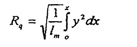
On calcule ensuite les quatre paramètres de rugosité, connus de l'homme du métier (voir la norme NF E 05-15 "Etat de surface des produits ― Prescriptions ― 1° Généralités ― Terminologie ― Définitions" de septembre 1984) :
l'écart absolu moyen Ra, l'écart quadratique moyen Rq, la rugosité maximale Rt, et
l'asymétrie de la distribution de l'amplitude (skewness) Sk défini comme
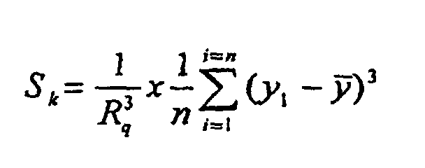
La demanderesse a observé que pour les échantillons de surface homogène, la valeur Sk se situe entre - 0,2 et + 0,3. Pour être apte par exemple à la fabrication de réflecteurs optiques, une valeur Sk comprise entre - 0,1 et + 0,2 est préférée. Les échantillons de surface non homogène, correspondant à l'art antérieur, ont une valeur Sk inférieure à - 0,4. A titre d'exemple, la demanderesse a trouvé des valeurs comprises entre - 0,45 et - 1,38 pour des échantillons en alliage 8011 obtenus par le procédé de coulée continue entre cylindres selon l'art antérieur.Applicant has observed that for samples of homogeneous surface, the value Sk is between - 0.2 and + 0.3. To be suitable for example in the manufacture of optical reflectors, a value Sk between -0.1 and +0.2 is preferred. The non-homogeneous surface samples, corresponding to the prior art, have a value Sk less than - 0.4. By way of example, the applicant has found values between -0.45 and -1.38 for alloy samples 8011 obtained by the continuous casting process between rolls according to the prior art.
Pour la caractérisation des défauts de rugosité, une méthode de rugosimétrie
mécanique en trois dimensions a été utilisée. L'échantillon est posé sur une table
croisée TIXY 200. La palpeur (modèle FRW 750 de la société Mahr Mesures), avec
un rayon de courbure de 5 µm, était conditionné par un appareil Perthometer PRK de
la société Mahr Mesures. Les données étaient enregistrées à l'aide d'une carte de
conversion analogique - digital dans un micro-ordinateur. La dimension du champ de
mesure était 20 mm x 20 mm, avec un pas de 40 µm en x et y. La résolution théorique
en profondeur était donnée par l'amplitude maximale du palpeur (100 µm) et les
caractéristiques du microprocesseur (16 bit), soit environ 0,024 µm. La rugosité en
trois dimensions a été calculée avec un logiciel fourni par la société Saphir selon les
équations suivantes :
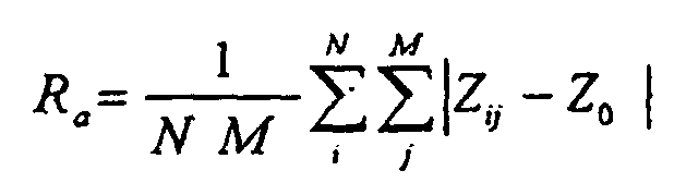
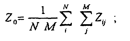


Le paramètre Ek, appelé parfois kurtosis en langue anglaise, caractérise l'aplatissement de la distribution ; il prend la valeur de 3 pour une Gaussienne idéale.The parameter Ek, sometimes called kurtosis in English, characterizes the flattening of the distribution; it takes the value of 3 for an ideal Gaussian.
Toutes ces mesures peuvent être faites sur la face supérieure, c'est-à-dire la face ayant été au contact du cylindre supérieur, en dehors de zones qui montrent des défauts accidentels tels que les rayures dues à la manutention ou des taches, pour des bandes brutes de coulée, des bandes simplement laminées à froid ou des bandes laminées à froid puis ayant subi des passes de finition avec des cylindres brillants (polis). Pour être représentatives de l'application visée, les mesures sont toutes effectuées sur des échantillons traités par anodisation sulfurique dans les conditions suivantes : concentration en acide sulfurique 200 g/l, température 20°C voltage 15 V. Ce traitement conduit à une épaisseur de couche d'oxyde de 1 µm. Il est éventuellement précédé d'un décapage basique préalable (par exemple, à une température de 60°C et pendant 7 minutes dans un bain à 50 g/l d'ALUMINUX 138, produit commercial à base de soude).All these measurements can be made on the upper face, that is to say the face having have been in contact with the upper cylinder, outside areas that show accidents such as scratches due to handling or stains, for castings, simply cold-rolled strip or rolled strip cold then having undergone finishing passes with shiny cylinders (polished). For be representative of the intended application, the measurements are all performed on samples treated by sulfuric anodizing under the following conditions: concentration of sulfuric acid 200 g / l, temperature 20 ° C voltage 15 V. This treatment leads to an oxide layer thickness of 1 μm. It is eventually preceded by a preliminary basic etching (for example, at a temperature of 60 ° C and during 7 minutes in a 50 g / l bath of ALUMINUX 138, commercial product at soda base).
Pour les bandes élaborées par coulée continue entre cylindres de l'art antérieur, la variation moyenne de SN est supérieure à 50%, aussi bien pour les bandes brutes de coulée que pour les bandes laminées à froid. Pour les bandes obtenues par le procédé selon l'invention, la variation moyenne est inférieure à 20% dans tous les cas. La différence ΔSN est inférieure à 20 pour les bandes brutes de coulée, et inférieure à 12 pour les bandes laminées à froid jusqu'à une épaisseur comprise entre 4 et 0,1 mm, et ayant subi avant anodisation un décapage basique. Elle est inférieure à 3,5, et même souvent à 0,5 pour les bandes ayant subi un laminage à froid final dit " brillant ", c'est-à-dire conduisant à une rugosité Ra inférieure à 0,2 µm, puis brillantées électrolytiquement avant l'anodisation de 1 µm.For the bands produced by continuous casting between rolls of the prior art, the average variation of S N is greater than 50%, both for the raw tapes and for the cold-rolled tapes. For the strips obtained by the method according to the invention, the average variation is less than 20% in all cases. The difference ΔS N is less than 20 for the raw tapes, and less than 12 for the cold-rolled tapes to a thickness between 4 and 0.1 mm, and underwent anodizing before basic etching. It is less than 3.5, and even often 0.5 for bands which have undergone a final cold rolling called "brilliant", that is to say leading to a roughness R a less than 0.2 microns, then electrolytically brightened before anodization of 1 μm.
D'une manière surprenante, il a été constaté que l'homogénéité de la surface de la face supérieure des bandes coulées par coulée continue entre cylindres est nettement améliorée par une légère modification de la machine de coulée représentée schématiquement à la figure 1.Surprisingly, it has been found that the homogeneity of the surface of the the upper face of the continuously cast cast-rolled strips is clearly improved by a slight modification of the casting machine shown schematically in Figure 1.
La machine comporte un bac de coulée (1) alimenté en alliage d'aluminium liquide et relié à un injecteur (2), constitué d'une lèvre inférieure (3) et d'une lèvre supérieure (4), amenant le métal liquide dans l'intervalle entre les deux cylindres (5) et (6) tournant en sens inverse. La bande (7) sort solidifiée de l'autre côté de l'intervalle entre cylindres. La modification selon l'invention consiste à utiliser un injecteur ayant une lèvre supérieure (4) en retrait d'une distance (d) par rapport à la lèvre inférieure (3). Ce retrait (d) est d'au moins 2 mm et, de préférence, d'au moins 5 mm. Pour éviter que cette disposition n'entraíne un afflux trop important de métal liquide dans l'intervalle entre les deux cylindres, il est souhaitable de réduire la pression métallostatique, c'est-à-dire la hauteur de métal, dans le bac de coulée (1), mesurée à partir du plan médian de coulée, à moins de 30 mm, de préférence à moins de 25 mm, et ce d'autant plus que le retrait (d) est plus important. Le retrait de la lèvre supérieure de l'injecteur permet en outre un positionnement plus fin de l'injecteur, ce qui évite le frottement accidentel sur la surface des cylindres, et améliore ainsi indirectement l'état de surface de la face inférieure de la bande coulée. Avec une hauteur de métal inférieure à 25 mm et un retrait de la lèvre supérieure de l'injecteur d'au moins 25 mm, la demanderesse a réussi a fabriquer des produits brillants en alliages des séries 1000 et 8000 finis par un laminage avec cylindres polis (laminage dit « skin pass ») qui avaient des propriétés d'usage identiques aux produits connus, élaborés par la voie plus coûteuse de coulée semi-continue et laminage à chaud. Ces produits ont pu être utilisés pour la fabrication de réflecteurs de lumière plats, pliés ou emboutis.The machine comprises a pouring pan (1) fed with liquid aluminum alloy and connected to an injector (2), consisting of a lower lip (3) and an upper lip (4), bringing the liquid metal into the gap between the two cylinders (5) and (6) turning in the opposite direction. The strip (7) is solidified on the other side of the gap between cylinders. The modification according to the invention consists in using an injector having an upper lip (4) set back a distance (d) from the lower lip (3). This shrinkage (d) is at least 2 mm and preferably at least 5 mm. For avoid that this provision causes an excessive influx of liquid metal in the interval between the two cylinders, it is desirable to reduce the pressure metallostatic, that is to say the height of metal, in the tundish (1), measured at from the median casting plane, less than 30 mm, preferably less than 25 mm, and especially since the withdrawal (d) is more important. The removal of the lip The upper part of the injector also allows a finer positioning of the injector. which avoids accidental friction on the surface of the cylinders, and thus improves indirectly the surface condition of the underside of the cast strip. With a metal height less than 25 mm and removal of the upper lip of the injector of at least 25 mm, the applicant has succeeded in producing brilliant products in alloys of the 1000 and 8000 series finished by rolling with polished cylinders (rolling called "skin pass") which had the same usage properties as the known products, developed by the more expensive route of semi-continuous casting and hot rolling. These products could be used for the manufacture of flat, folded or pressings.
L'invention est applicable à tous les alliages d'aluminium susceptibles d'être coulés en continu entre cylindres. A titre d'exemple, la demanderesse a obtenu de bons résultats avec certains alliages de la série 3000 et avec certains alliages de type Al-Mg à faible teneur en magnésium tels que le 5005.The invention is applicable to all aluminum alloys capable of being cast in continuous between cylinders. For example, the plaintiff obtained good results with certain alloys from the 3000 series and with some low Al-Mg alloys magnesium content such as the 5005.
L'invention est particulièrement intéressante pour les alliages AlFeSi des séries 1000 et 8000, contenant de 0,01 à 2% en poids de fer, et de 0,1 à 2% de silicium. En effet, ces alliages, lorsqu'ils sont coulés en continu entre cylindres, présentent des caractéristiques mécaniques nettement plus élevées que celles obtenues par coulée traditionnelle et laminage à chaud, ce qui facilite leur laminage " brillant ". Une des raisons de la résistance mécanique plus élevée des bandes obtenues par coulée continue pour ce type d'alliage est que la quantité de fer en solution solide dans l'aluminium est plus élevée. Pour un alliage contenant plus de 0,01% (100 ppm) de fer, la quantité de fer en solution solide est supérieure à 50 ppm + 0,03 x (teneur Fe en ppm). Un autre avantage d'avoir un taux élevé de fer en solution solide est, pour une teneur donnée en fer, de diminuer les composés intermétalliques au fer , dont la présence en surface est une source de défauts optiques. Pour des raisons de même nature, l'invention est également particulièrement intéressante pour les alliages à bas Mg (Mg < 1,5%). The invention is particularly interesting for AlFeSi alloys of the 1000 series and 8000, containing from 0.01 to 2% by weight of iron, and from 0.1 to 2% of silicon. Indeed, these alloys, when they are continuously cast between cylinders, have mechanical characteristics significantly higher than those obtained by casting traditional and hot rolling, which facilitates their rolling "brilliant". One of the reasons for the higher mechanical strength of the strips obtained by casting continuous for this type of alloy is that the amount of iron in solid solution in aluminum is higher. For an alloy containing more than 0.01% (100 ppm) of iron, the amount of iron in solid solution is greater than 50 ppm + 0.03 x (Fe content in ppm). Another advantage of having a high level of iron in solid solution is, for a given iron content, to decrease the intermetallic compounds to iron, whose surface presence is a source of optical defects. For the same reasons nature, the invention is also particularly interesting for low-alloys Mg (Mg <1.5%).
Par ailleurs, on obtient en surface une taille de grains, définie comme la largeur moyenne des grains en surface, mesurée perpendiculairement au sens de laminage par analyse d'image, inférieure à 20 µm, et souvent à 15 µm, aussi bien sur les bandes brutes de coulée que sur les bandes laminées à froid, ce qui diminue certains défauts d'aspect comme le lignage. Cette caractéristique des bandes suivant l'invention est également favorable pour une mise en forme ultérieure, par exemple par emboutissage.In addition, a grain size is obtained on the surface, defined as the width average grain surface, measured perpendicular to the direction of rolling by image analysis, less than 20 μm, and often 15 μm, both on casting only on cold-rolled strips, which reduces some of the defects look like lineage. This characteristic of the bands according to the invention is also favorable for later formatting, for example by stamping.
On a préparé un alliage EN AW-1085 (selon la norme NF EN 573-3) de composition
(% en poids): Si = 0,040 Fe = 0,038 Cu = 0,0017 Mn = 0,0022 Mg =
0,0032 Zn = 0,002 Ti = 0,02
avec addition de 3 kg/t d'affinant au titane-bore. Le métal a été traité à l'argon dans
une poche de coulée Alpur ® de Pechiney Rhenalu, puis coulé en continu sur une
machine de coulée entre cylindres JUMBO 3 CM ® de Pechiney Rhenalu.An alloy EN AW-1085 (according to the standard NF EN 573-3) of composition (% by weight) was prepared: Si = 0.040 Fe = 0.038 Cu = 0.0017 Mn = 0.0022 Mg = 0.0032 Zn = 0.002 Ti = 0.02
with the addition of 3 kg / t of titanium-boron refining. The metal was treated with argon in a Pechiney Rhenalu Alpur ® casting ladle and then cast continuously on a JUMBO 3 CM ® cylinder casting machine from Pechiney Rhenalu.
Le diamètre des cylindres était de 1150 mm, avec un entrefer entre les deux cylindres de 2,3 mm. L'injecteur en céramique de marque Styrite ® comportait une lèvre supérieure en retrait de 7 mm par rapport à la lèvre inférieure, et était alimenté par un bac de coulée avec une hauteur de métal liquide d'environ 18 mm. La coulée a été faite à une largeur de 1370 mm, une épaisseur de bande coulée de 3,6 mm, une vitesse de coulée de 1,6 m/mn et un effort entre cylindres de 800 t/m de largeur de bande. La bande a été ensuite laminée à froid à une épaisseur de 0,4 mm.The diameter of the cylinders was 1150 mm, with an air gap between the two cylinders 2.3 mm. The Styrite ® brand ceramic injector featured a lip 7 mm lower than the lower lip, and was powered by a casting tray with a liquid metal height of about 18 mm. The casting was made at a width of 1370 mm, a cast strip thickness of 3.6 mm, a speed casting speed of 1.6 m / min and an inter-roll force of 800 t / m bandwidth. The The strip was then cold rolled to a thickness of 0.4 mm.
On a préparé par ailleurs des bandes de même composition par la méthode habituelle de coulée semi-continue verticale, laminage à chaud des plateaux puis laminage à froid jusqu'à la même épaisseur de 0,4 mm à deux taux d'écrouissage différents.In addition, strips of the same composition have been prepared by the usual method. vertical semi-continuous casting, hot rolling of trays then cold rolling up to the same thickness of 0.4 mm at two different work-hardening rates.
On a comparé les caractéristiques mécaniques des bandes à savoir la résistance à la
rupture Rm (en MPa), la limite d'élasticité R0.2 (en MPa), l'allongement (en %) et le
taux d'écrouissage n (en %). Les résultats sont donnés au tableau 1 et montrent qu'on
obtient pour cet alliage 1085, selon l'invention, des valeurs de Rm > 165 Mpa, R0,2 >
160 Mpa et A > 6%.
On constate que la coulée continue conduit à la fois à une résistance mécanique plus élevée avec un taux d'écrouissage plus faible, facilitant ainsi le laminage brillant, ainsi qu'à un meilleur allongement permettant une mise en forme plus aisée.It can be seen that continuous casting leads to both greater mechanical strength with a lower work hardening rate, thus facilitating shiny rolling, as well as than a better elongation for easier shaping.
On a constaté également que la taille des grains en surface, déterminée par analyse d'image, était de 7 µm pour des bandes suivant l'invention et de 80 µm pour les bandes issues de la coulée semi-continue verticale.It was also found that the size of the grains on the surface, determined by analysis image, was 7 μm for the bands according to the invention and 80 μm for the bands from vertical semi-continuous casting.
On a préparé également des bandes de même composition toujours avec la coulée continue entre cylindres JUMBO 3CM ® de Péchiney Rhénalu mais avec un injecteur de l'art antérieur sans retrait de la lèvre supérieure. Ces bandes ont suivi jusqu'à une épaisseur de 0,4 mm le même processus que les bandes suivant l'invention.We have also prepared bands of the same composition always with the casting continuous between JUMBO 3CM ® cylinders of Péchiney Rhénalu but with an injector of the prior art without removal of the upper lip. These bands followed up to thickness of 0.4 mm the same process as the strips according to the invention.
Les bandes suivant l'invention et les bandes issues d'une coulée continue entre
cylindres avec un injecteur de l'art antérieur ont subi ensuite deux passes de finition
avec des cylindres brillants de 0,4 mm jusqu'à 0,35 mm. Après brillantage
électrolytique puis anodisation à l'acide sulfurique d'une épaisseur de 1 µm, on a
mesuré des propriétés optiques des bandes par le système RM 400 de la Société
RODENSTOCK. Les résultats sont donnés au tableau 2 .
Des enregistrements de l'indice de rugosité sur les bandes sont données en fig. 2 et 3. Records of the roughness index on the strips are given in fig. 2 and 3.
On a préparé un alliage EN AW-1070A (selon la norme NF EN 573-3) : Si = 0,06 Fe = 0,12 Ti = 0,015 avec addition de 1,5 kg/t d'affinant au titane-bore. Le métal a été coulé en continu sur la même machine de coulée entre cylindre JUMBO 3 CM ® de Péchiney Rhénalu que celle de l'exemple 1.An EN AW-1070A alloy (according to standard NF EN 573-3) was prepared: Si = 0.06 Fe = 0.12 Ti = 0.015 with addition of 1.5 kg / t of titanium-boron refining. Metal was cast continuously on the same JUMBO 3 CM ® cylinder casting machine of Péchiney Rhénalu than that of example 1.
L'injecteur, également en céramique de marque Styrite ®, comportait une lèvre supérieure en retrait de 10 mm par rapport à la lèvre inférieure et était alimenté par un bac de coulée avec une hauteur de métal liquide d'environ 18 mm. La largeur de bande était de 1370 mm, l'épaisseur de la bande coulée de 3 mm, la vitesse de coulée de 2 m/mn et l'effort entre cylindres de 900 t par mètre de largeur de bande.The injector, also in Styrite ® brand ceramic, had a lip upper back 10 mm from the lower lip and was powered by a casting tray with a liquid metal height of about 18 mm. The width of band was 1370 mm, the thickness of the casting band 3 mm, the casting speed of 2 m / min and the effort between cylinders of 900 t per meter of bandwidth.
Les bandes ainsi coulées ont ensuite été laminées à froid jusqu'à une épaisseur de 0,8 mm puis ont subi deux passes de laminage avec des cylindres brillants jusqu'à 0,5 mm. Des échantillons de bandes ont été prélevés au fur et à mesure, d'abord de bandes brutes de coulée à 3 mm, ensuite de bandes après laminage à froid de 0,8 mm, et enfin de bandes après laminage " brillant " à 0,5 mm.The strips thus cast were then cold-rolled to a thickness of 0.8 mm and then underwent two rolling passes with cylinders shining up to 0.5 mm. Samples of tapes were taken as and when tapes first castings at 3 mm, then strips after cold rolling of 0.8 mm, and finally of strips after "glossy" lamination at 0.5 mm.
Les échantillons de bandes brutes de coulée à 3 mm ont été traitées par anodisation
sulfurique d'une épaisseur de 1 µm. Les échantillons de bandes après laminage à froid
à 0,8 mm ont subi un décapage basique sur 10 µm puis une anodisation sulfurique
d'une épaisseur de 1 µm. Les échantillons de bandes après laminage brillant à 0,5 mm
ont subi successivement un brillantage électrolytique et une anodisation sulfurique
d'épaisseur 1 µm.Samples of 3 mm cast tapes were treated by anodizing
sulfuric acid with a thickness of 1 μm. Strip samples after cold rolling
at 0.8 mm have undergone a basic etching on 10 μm then a sulfuric anodization
with a thickness of 1 μm. The strip samples after glossy lamination to 0.5 mm
have successively undergone electrolytic brightening and sulfuric anodizing
of
On a préparé par ailleurs des bandes de même composition toujours avec la coulée
continue entre cylindres JUMBO 3CM ® de Péchiney Rhénalu mais avec un injecteur
de l'art antérieur sans retrait de la lèvre supérieure. Les bandes ont suivi jusqu'à 0,5
mm le même processus que les bandes suivant l'invention et ont subi, comme celles-ci,
un brillantage électrolytique et une anodisation sulfurique d'épaisseur 1 µm.We have also prepared tapes of the same composition always with casting
continuous between JUMBO 3CM ® cylinders of Péchiney Rhénalu but with an injector
of the prior art without removal of the upper lip. Bands followed up to 0.5
mm the same process as the bands following the invention and have suffered, like these,
an electrolytic brilliance and a sulfuric anodization of
On a mesuré les propriétés optiques de l'ensemble des échantillons par le système RM
400 de la Société RODENSTOCK. Les résultats sont donnés au tableau 3.
Par ailleurs on a mesuré sur les bandes suivant l'invention des tailles de grains en surface de 12 µm alors que les bandes de même composition, ayant subi les mêmes gammes de laminage à froid mais issues du procédé classique (coulée semi-continue verticale puis laminage à chaud des plateaux) ont des tailles de grains en surface de l'ordre de 70 µm.In addition, the following bands were measured on the belts according to the invention 12 μm while bands of the same composition, having undergone the same cold rolling ranges but from the conventional process (semi-continuous casting vertical then hot rolling trays) have grain sizes in surface of the order of 70 microns.
Par coulée continue entre cylindres, on a effectué sept coulées différentes avec les
caractéristiques suivantes:
La coulée R5 correspond à celle de l'exemple 1, effectuée avec le procédé de coulée continue entre cylindres selon l'invention.The casting R5 corresponds to that of Example 1, carried out with the casting process continuous between cylinders according to the invention.
La coulée R7 correspond à celle de l'exemple 1, effectuée selon l'art antérieur avec un injecteur traditionnel.The casting R7 corresponds to that of Example 1, carried out according to the prior art with a traditional injector.
Les autres coulées ont été effectuées avec une machine de coulée continue semblable à celle décrite dans l'exemple 1.The other pours were made with a similar continuous casting machine to that described in Example 1.
Les résultats des caractérisations optiques et rugosimétriques, après décapage et
anodisation des bandes brutes de coulée, étaient les suivants :
On constate que l'écart-type sur le paramètre L*moyen correspond à la réponse visuelle, à l'exception de l'échantillon R1 pour lequel le pas d'oscillation du niveau de gris est trop faible par rapport au diamètre de l'aire d'une mesure individuelle. Sur le plan industriel, les échantillons R1 et R7 ne sont pas utilisables pour les applications visées, car leur état de surface est esthétiquement et optiquement inacceptable.We find that the standard deviation on the average L * parameter corresponds to the response except for sample R1 for which the oscillation step of the level of Gray is too small in relation to the diameter of the area of an individual measurement. On the In industrial terms, samples R1 and R7 are not usable for applications because their surface condition is aesthetically and optically unacceptable.
La demanderesse a constaté qu'en rugosimétrie 3D, seuls les paramètres Sk et Ek permettent de discriminer les produits obtenus par le procédé des produits inaptes à des applications exigeantes en matière d'aspect de surface.The Applicant has found that in 3D rugosimetry, only Sk and Ek parameters discriminate products obtained by the process of products that are unfit for demanding applications in surface appearance.
La demanderesse a constaté par ailleurs que pour avoir une surface qui permet les applications visées, il faut que l'une ou préférentiellement toutes les deux des conditions suivantes soient remplies:
- la valeur de Sk en rugosimétrie 3D selon la procédure décrite soit supérieure à -2,0 et préférentiellement supérieure à -1,0 ;
- la valeur Ek en rugosimétrie 3D doit être inférieure à 15 et préférentiellement inférieure à 8.
- the Sk value in 3D rugosimetry according to the procedure described is greater than -2.0 and preferably greater than -1.0;
- the Ek value in 3D rugosimetry must be less than 15 and preferably less than 8.
La demanderesse a observé qu'il est préférable qu'en plus de l'une ou des deux conditions qui viennent d'être mentionnées, la surface ait également un écart-type sur la valeur L*moyen inférieur à 0,5 et préférentiellement inférieur à 0,3.The Applicant has observed that it is preferable that in addition to one or both conditions just mentioned, the surface also has a standard deviation on the average L * value less than 0.5 and preferably less than 0.3.
Claims (8)
- Process for manufacturing an aluminium alloy strip with a better surface uniformity on its upper face than on its lower face, by continuous casting between two cooled cylinders (5) and (6), from a pouring bath (1) containing the liquid metal connected to an injector (2) composed of a lower lip (3) and an upper lip (4), carrying the liquid metal into the gap between the two cylinders, characterised in that the upper lip (3) of the injector (2) is set back at least 2 mm from the lower lip (4).
- Process according to claim 2, characterised in that the upper lip (3) of the injector (2) is set back at least 5 mm from the lower lip (4).
- Process according to either claim 1 or 2, characterised in that the depth of liquid metal in the pouring bath (1) measured from the median casting plane is less than 30 mm.
- Process according to claim 8, characterised in that the depth of liquid metal in the pouring bath (1) measured from the median pouring plane is less than 25 mm.
- Use of a strip obtained by a process according to any one of claims 1 to 4, for manufacturing of anodised and possibly enamelled plates for building.
- Use of a strip obtained by a process according to any one of claims 1 to 4 for manufacturing of stamped parts.
- Use of a strip obtained by a process according to any one of claims 1 to 4 for manufacturing of optical reflectors.
- 1085 alloy strip produced by continuous casting between cylinders according to one of claims 1 to 4, characterised in that after one or several cold rolling passes with a total work hardening ratio of less than 85%, it has one of the following groups of properties:a) Rm > 165 MPa and A > 6%,b) R0.2 > 160 MPa and A > 6%.
Applications Claiming Priority (3)
| Application Number | Priority Date | Filing Date | Title |
|---|---|---|---|
| FR9801987 | 1998-02-13 | ||
| FR9801987A FR2774930B1 (en) | 1998-02-13 | 1998-02-13 | STRIPS OF ALUMINUM ALLOY WITH HIGH SURFACE HOMOGENEITY AND METHOD OF MANUFACTURING SUCH STRIPS |
| PCT/FR1999/000319 WO1999041031A1 (en) | 1998-02-13 | 1999-02-12 | Aluminium alloy strips with high surface homogeneity and method for making same |
Publications (2)
| Publication Number | Publication Date |
|---|---|
| EP1056560A1 EP1056560A1 (en) | 2000-12-06 |
| EP1056560B1 true EP1056560B1 (en) | 2005-04-27 |
Family
ID=9523123
Family Applications (1)
| Application Number | Title | Priority Date | Filing Date |
|---|---|---|---|
| EP99903745A Expired - Lifetime EP1056560B1 (en) | 1998-02-13 | 1999-02-12 | Method for making aluminium alloy strips with high surface homogeneity |
Country Status (11)
| Country | Link |
|---|---|
| US (2) | US6834708B1 (en) |
| EP (1) | EP1056560B1 (en) |
| JP (1) | JP2002502708A (en) |
| CN (1) | CN1222381C (en) |
| AT (1) | ATE294038T1 (en) |
| AU (1) | AU2429499A (en) |
| BR (1) | BR9907880A (en) |
| DE (1) | DE69924981D1 (en) |
| FR (1) | FR2774930B1 (en) |
| NO (1) | NO20004061L (en) |
| WO (1) | WO1999041031A1 (en) |
Cited By (5)
| Publication number | Priority date | Publication date | Assignee | Title |
|---|---|---|---|---|
| DE102009012984A1 (en) * | 2009-03-12 | 2010-09-23 | Salzgitter Flachstahl Gmbh | Casting nozzle for a horizontal strip casting plant |
| DE102015114725B3 (en) * | 2015-09-03 | 2016-12-08 | Salzgitter Flachstahl Gmbh | Melt feed system for a horizontal strip caster |
| WO2017032371A2 (en) | 2015-08-21 | 2017-03-02 | Schaeffler Technologies AG & Co. KG | Force simulation device on an actuation element of a vehicle, preferably a pedal force simulator |
| US10957942B2 (en) | 2016-09-14 | 2021-03-23 | Wirtz Manufacturing Co., Inc. | Continuous lead strip casting line, caster, and nozzle |
| US10960461B2 (en) | 2016-09-14 | 2021-03-30 | Wirtz Manufacturing Co., Inc. | Continuous lead strip casting line, caster, and nozzle |
Families Citing this family (6)
| Publication number | Priority date | Publication date | Assignee | Title |
|---|---|---|---|---|
| JP4203508B2 (en) * | 2006-03-08 | 2009-01-07 | 株式会社神戸製鋼所 | Method for producing aluminum alloy cast plate |
| EP3444719B1 (en) * | 2017-08-14 | 2021-07-21 | Unify Patente GmbH & Co. KG | Method and system for a client to server deployment via an online distribution platform |
| CN111761036B (en) * | 2020-07-08 | 2022-03-01 | 甘肃东兴铝业有限公司 | Casting and rolling method for 6xxx series aluminum alloy plate for automobile |
| TWI733592B (en) * | 2020-09-24 | 2021-07-11 | 中國鋼鐵股份有限公司 | Aluminum alloy sheet and method for manufacturing the same |
| CN113560515B (en) * | 2021-06-21 | 2023-01-03 | 杭州电子科技大学 | Tundish for rare earth magnetic material rapid-hardening casting belt and casting method |
| CN113857445B (en) * | 2021-09-26 | 2023-10-03 | 云南浩鑫铝箔有限公司 | Casting nozzle structure and sliding edge production process using same |
Family Cites Families (14)
| Publication number | Priority date | Publication date | Assignee | Title |
|---|---|---|---|---|
| NL235564A (en) | 1958-01-31 | |||
| FR1198006A (en) * | 1958-01-31 | 1959-12-04 | Pechiney Prod Chimiques Sa | Continuous metal casting |
| DE2443068A1 (en) * | 1974-09-09 | 1976-03-25 | Leichtmetall Gmbh | METHOD AND DEVICE FOR POWING THE MELT INTO THE SOLIDIZING AREA OF A BELT CASTING MACHINE |
| US4054173A (en) | 1974-12-23 | 1977-10-18 | Hunter Engineering Co., Inc. | Apparatus for producing completely recrystallized metal sheet |
| AU507351B2 (en) * | 1974-12-23 | 1980-02-14 | Hunter Engineering Co. Inc. | Roll casting |
| FR2398565A1 (en) * | 1977-07-27 | 1979-02-23 | Scal Gp Condit Aluminium | LIQUID METAL FEED NOZZLE FOR CONTINUOUS TAPE CASTING MACHINE |
| CH657546A5 (en) * | 1982-12-16 | 1986-09-15 | Alusuisse | METHOD FOR PRODUCING A TAPE SUITABLE FOR THE PRODUCTION OF CAN LIDS. |
| US4681152A (en) * | 1985-10-04 | 1987-07-21 | Hunter Engineering Company, Inc. | Continuous casting aluminum alloy |
| GB2198976B (en) * | 1986-12-19 | 1990-10-17 | Davy Mckeen | Roll caster |
| US5350010A (en) * | 1992-07-31 | 1994-09-27 | Fuji Photo Film Co., Ltd. | Method of producing planographic printing plate support |
| JP3859228B2 (en) * | 1993-09-21 | 2006-12-20 | アルキャン・インターナショナル・リミテッド | Aluminum sheet with rough surface |
| TW374096B (en) * | 1995-01-10 | 1999-11-11 | Nihon Parkerizing | Process for hot dip-coating a steel material with a molten aluminum alloy according to an one-stage metal alloy coating method using a flux |
| FR2737430B1 (en) * | 1995-08-03 | 1997-09-05 | Pechiney Rhenalu | METHOD AND DEVICE FOR STARTING A CONTINUOUS CASTING MACHINE BETWEEN CYLINDERS |
| EP0821074A1 (en) * | 1996-07-25 | 1998-01-28 | Alusuisse Technology & Management AG | Process for producing a strip of an aluminium alloy for lithographic printing plates |
-
1998
- 1998-02-13 FR FR9801987A patent/FR2774930B1/en not_active Expired - Fee Related
-
1999
- 1999-02-12 JP JP2000531266A patent/JP2002502708A/en not_active Abandoned
- 1999-02-12 WO PCT/FR1999/000319 patent/WO1999041031A1/en active IP Right Grant
- 1999-02-12 CN CNB998026727A patent/CN1222381C/en not_active Expired - Fee Related
- 1999-02-12 AT AT99903745T patent/ATE294038T1/en not_active IP Right Cessation
- 1999-02-12 AU AU24294/99A patent/AU2429499A/en not_active Abandoned
- 1999-02-12 DE DE69924981T patent/DE69924981D1/en not_active Expired - Lifetime
- 1999-02-12 BR BR9907880-5A patent/BR9907880A/en not_active Application Discontinuation
- 1999-02-12 EP EP99903745A patent/EP1056560B1/en not_active Expired - Lifetime
- 1999-02-12 US US09/582,625 patent/US6834708B1/en not_active Expired - Fee Related
-
2000
- 2000-08-11 NO NO20004061A patent/NO20004061L/en not_active Application Discontinuation
-
2001
- 2001-12-13 US US10/013,681 patent/US6948550B2/en not_active Expired - Fee Related
Non-Patent Citations (1)
| Title |
|---|
| BRODMANN R.; GAST T.; THURN G.: "An optical instrument for measuring the surface roughness in production control", CIRP ANNALS, vol. 33, no. 1, 1984, pages 403 - 406 * |
Cited By (7)
| Publication number | Priority date | Publication date | Assignee | Title |
|---|---|---|---|---|
| DE102009012984A1 (en) * | 2009-03-12 | 2010-09-23 | Salzgitter Flachstahl Gmbh | Casting nozzle for a horizontal strip casting plant |
| DE102009012984B4 (en) * | 2009-03-12 | 2013-05-02 | Salzgitter Flachstahl Gmbh | Casting nozzle for a horizontal strip casting plant |
| WO2017032371A2 (en) | 2015-08-21 | 2017-03-02 | Schaeffler Technologies AG & Co. KG | Force simulation device on an actuation element of a vehicle, preferably a pedal force simulator |
| DE102015114725B3 (en) * | 2015-09-03 | 2016-12-08 | Salzgitter Flachstahl Gmbh | Melt feed system for a horizontal strip caster |
| WO2017036456A1 (en) | 2015-09-03 | 2017-03-09 | Sms Group Gmbh | Melt charging system for a horizontal continuous casting system |
| US10957942B2 (en) | 2016-09-14 | 2021-03-23 | Wirtz Manufacturing Co., Inc. | Continuous lead strip casting line, caster, and nozzle |
| US10960461B2 (en) | 2016-09-14 | 2021-03-30 | Wirtz Manufacturing Co., Inc. | Continuous lead strip casting line, caster, and nozzle |
Also Published As
| Publication number | Publication date |
|---|---|
| JP2002502708A (en) | 2002-01-29 |
| US20020084056A1 (en) | 2002-07-04 |
| AU2429499A (en) | 1999-08-30 |
| ATE294038T1 (en) | 2005-05-15 |
| FR2774930B1 (en) | 2000-05-19 |
| BR9907880A (en) | 2000-10-17 |
| US6948550B2 (en) | 2005-09-27 |
| US6834708B1 (en) | 2004-12-28 |
| CN1289275A (en) | 2001-03-28 |
| CN1222381C (en) | 2005-10-12 |
| NO20004061L (en) | 2000-10-13 |
| FR2774930A1 (en) | 1999-08-20 |
| NO20004061D0 (en) | 2000-08-11 |
| EP1056560A1 (en) | 2000-12-06 |
| WO1999041031A1 (en) | 1999-08-19 |
| DE69924981D1 (en) | 2005-06-02 |
Similar Documents
| Publication | Publication Date | Title |
|---|---|---|
| EP1056560B1 (en) | Method for making aluminium alloy strips with high surface homogeneity | |
| EP2263811A1 (en) | Aluminum alloy plate and process for producing the same | |
| CA1308337C (en) | Method for making lithoplate | |
| CH629410A5 (en) | METHOD FOR MANUFACTURING A COMPOSITE STRIP BY PLATING. | |
| RU2537835C2 (en) | Lithographic band for electrochemical graining, as well as method for its manufacture | |
| EP1187691B1 (en) | Method for continuously casting ferritic stainless steel strips free of microcracks | |
| US5779824A (en) | Aluminum alloy support for planographic printing plate and method for producing the same | |
| WO2019106254A1 (en) | Aluminium alloy flat product having improved thickness properties | |
| EP2802427B1 (en) | Double-jet cooling device for semicontinuous vertical casting mould | |
| EP1175516B1 (en) | Production of aluminum alloy strip for use in making thin gauge foils | |
| EP1259654A1 (en) | Method for making aluminium alloy strips for making can bodies | |
| JP4134517B2 (en) | Aluminum foil and method for producing the same | |
| US11130171B2 (en) | Method for reducing target surface features in continuous casting | |
| EP3965977A1 (en) | Method for manufacturing long metal stopper caps comprising a skirt having a constant thickness | |
| JP4250030B2 (en) | Aluminum alloy plate for glittering wheel rim and manufacturing method thereof | |
| EP0665448A1 (en) | Aluminium sheets or strips having reproducible and improved optical properties | |
| JP2008019467A (en) | Aluminum alloy sheet with excellent surface quality after chromating for can end, and its manufacturing method | |
| US11807027B2 (en) | Litho strip having flat topography and printing plate produced therefrom | |
| CZ20002946A3 (en) | Strip of aluminium alloy, process for producing thereof by continuous casting process and use of such strip | |
| FR2637616A1 (en) | Process for the manufacture of large mirrors made of high purity aluminium | |
| CA1195821A (en) | Aluminum alloy can stock and process of manufacture | |
| FR2628348A1 (en) | METHOD FOR INCREASING THE FRICTION BETWEEN THE TOOL AND THE PRODUCT TO BE ROLLED, AND APPROPRIATE CYLINDER FOR CARRYING OUT SAID METHOD | |
| WO2024018147A1 (en) | Method for manufacturing a 7xxx aluminum alloy sheet and 7xxx aluminum alloy sheet | |
| Willis et al. | Melt-Spinning a Commercial Aluminium Alloy | |
| EP0666333A1 (en) | Fatigue-resistant aluminium alloy thick plate and process for making |
Legal Events
| Date | Code | Title | Description |
|---|---|---|---|
| PUAI | Public reference made under article 153(3) epc to a published international application that has entered the european phase |
Free format text: ORIGINAL CODE: 0009012 |
|
| 17P | Request for examination filed |
Effective date: 20000620 |
|
| AK | Designated contracting states |
Kind code of ref document: A1 Designated state(s): AT DE FR GB IT |
|
| 17Q | First examination report despatched |
Effective date: 20010521 |
|
| GRAP | Despatch of communication of intention to grant a patent |
Free format text: ORIGINAL CODE: EPIDOSNIGR1 |
|
| RTI1 | Title (correction) |
Free format text: METHOD FOR MAKING ALUMINIUM ALLOY STRIPS WITH HIGH SURFACE HOMOGENEITY |
|
| GRAS | Grant fee paid |
Free format text: ORIGINAL CODE: EPIDOSNIGR3 |
|
| GRAA | (expected) grant |
Free format text: ORIGINAL CODE: 0009210 |
|
| AK | Designated contracting states |
Kind code of ref document: B1 Designated state(s): AT DE FR GB IT |
|
| PG25 | Lapsed in a contracting state [announced via postgrant information from national office to epo] |
Ref country code: GB Free format text: LAPSE BECAUSE OF FAILURE TO SUBMIT A TRANSLATION OF THE DESCRIPTION OR TO PAY THE FEE WITHIN THE PRESCRIBED TIME-LIMIT Effective date: 20050427 Ref country code: AT Free format text: LAPSE BECAUSE OF FAILURE TO SUBMIT A TRANSLATION OF THE DESCRIPTION OR TO PAY THE FEE WITHIN THE PRESCRIBED TIME-LIMIT Effective date: 20050427 |
|
| REG | Reference to a national code |
Ref country code: GB Ref legal event code: FG4D Free format text: NOT ENGLISH |
|
| REF | Corresponds to: |
Ref document number: 69924981 Country of ref document: DE Date of ref document: 20050602 Kind code of ref document: P |
|
| PG25 | Lapsed in a contracting state [announced via postgrant information from national office to epo] |
Ref country code: DE Free format text: LAPSE BECAUSE OF FAILURE TO SUBMIT A TRANSLATION OF THE DESCRIPTION OR TO PAY THE FEE WITHIN THE PRESCRIBED TIME-LIMIT Effective date: 20050728 |
|
| GBV | Gb: ep patent (uk) treated as always having been void in accordance with gb section 77(7)/1977 [no translation filed] |
Effective date: 20050427 |
|
| RAP2 | Party data changed (patent owner data changed or rights of a patent transferred) |
Owner name: NOVELIS, INC. |
|
| PLBE | No opposition filed within time limit |
Free format text: ORIGINAL CODE: 0009261 |
|
| STAA | Information on the status of an ep patent application or granted ep patent |
Free format text: STATUS: NO OPPOSITION FILED WITHIN TIME LIMIT |
|
| 26N | No opposition filed |
Effective date: 20060130 |
|
| REG | Reference to a national code |
Ref country code: FR Ref legal event code: TP |
|
| REG | Reference to a national code |
Ref country code: FR Ref legal event code: CL |
|
| REG | Reference to a national code |
Ref country code: FR Ref legal event code: AU |
|
| REG | Reference to a national code |
Ref country code: FR Ref legal event code: PLFP Year of fee payment: 18 |
|
| REG | Reference to a national code |
Ref country code: FR Ref legal event code: PLFP Year of fee payment: 19 |
|
| REG | Reference to a national code |
Ref country code: FR Ref legal event code: PLFP Year of fee payment: 20 |
|
| PGFP | Annual fee paid to national office [announced via postgrant information from national office to epo] |
Ref country code: IT Payment date: 20180222 Year of fee payment: 20 Ref country code: FR Payment date: 20180227 Year of fee payment: 20 |