EP1055940B1 - Verfahren und System zur Messung der Entfernung zwischen zwei Objekten mittels aufeinanderfolgender orthogonaler Pseudozufallszahlen - Google Patents
Verfahren und System zur Messung der Entfernung zwischen zwei Objekten mittels aufeinanderfolgender orthogonaler Pseudozufallszahlen Download PDFInfo
- Publication number
- EP1055940B1 EP1055940B1 EP00490019A EP00490019A EP1055940B1 EP 1055940 B1 EP1055940 B1 EP 1055940B1 EP 00490019 A EP00490019 A EP 00490019A EP 00490019 A EP00490019 A EP 00490019A EP 1055940 B1 EP1055940 B1 EP 1055940B1
- Authority
- EP
- European Patent Office
- Prior art keywords
- signal
- pseudo
- random
- interrogator
- interrogation
- Prior art date
- Legal status (The legal status is an assumption and is not a legal conclusion. Google has not performed a legal analysis and makes no representation as to the accuracy of the status listed.)
- Expired - Lifetime
Links
- 238000000034 method Methods 0.000 title claims abstract description 32
- 230000004044 response Effects 0.000 claims abstract description 84
- 238000001514 detection method Methods 0.000 claims description 25
- 238000005259 measurement Methods 0.000 claims description 24
- 238000001228 spectrum Methods 0.000 claims description 7
- 238000004364 calculation method Methods 0.000 claims description 6
- 230000001360 synchronised effect Effects 0.000 claims description 4
- 230000002596 correlated effect Effects 0.000 claims description 3
- 230000008054 signal transmission Effects 0.000 claims description 2
- 230000001960 triggered effect Effects 0.000 claims 1
- 238000012545 processing Methods 0.000 description 22
- 230000000875 corresponding effect Effects 0.000 description 12
- 230000005540 biological transmission Effects 0.000 description 11
- 230000006870 function Effects 0.000 description 11
- 238000010586 diagram Methods 0.000 description 9
- 230000008901 benefit Effects 0.000 description 8
- 238000013475 authorization Methods 0.000 description 4
- 238000004891 communication Methods 0.000 description 4
- 230000003071 parasitic effect Effects 0.000 description 4
- 230000003321 amplification Effects 0.000 description 3
- 238000006243 chemical reaction Methods 0.000 description 3
- 238000003199 nucleic acid amplification method Methods 0.000 description 3
- 230000017105 transposition Effects 0.000 description 3
- 238000012935 Averaging Methods 0.000 description 2
- 239000000969 carrier Substances 0.000 description 2
- 238000011084 recovery Methods 0.000 description 2
- 230000000630 rising effect Effects 0.000 description 2
- 230000003595 spectral effect Effects 0.000 description 2
- 238000012546 transfer Methods 0.000 description 2
- 239000008186 active pharmaceutical agent Substances 0.000 description 1
- 238000005311 autocorrelation function Methods 0.000 description 1
- 230000008859 change Effects 0.000 description 1
- 238000005314 correlation function Methods 0.000 description 1
- 230000001627 detrimental effect Effects 0.000 description 1
- 230000004069 differentiation Effects 0.000 description 1
- 235000021183 entrée Nutrition 0.000 description 1
- 230000010363 phase shift Effects 0.000 description 1
- 230000008569 process Effects 0.000 description 1
- 230000001902 propagating effect Effects 0.000 description 1
- 230000001105 regulatory effect Effects 0.000 description 1
Images


Classifications
-
- G—PHYSICS
- G01—MEASURING; TESTING
- G01S—RADIO DIRECTION-FINDING; RADIO NAVIGATION; DETERMINING DISTANCE OR VELOCITY BY USE OF RADIO WAVES; LOCATING OR PRESENCE-DETECTING BY USE OF THE REFLECTION OR RERADIATION OF RADIO WAVES; ANALOGOUS ARRANGEMENTS USING OTHER WAVES
- G01S13/00—Systems using the reflection or reradiation of radio waves, e.g. radar systems; Analogous systems using reflection or reradiation of waves whose nature or wavelength is irrelevant or unspecified
- G01S13/74—Systems using reradiation of radio waves, e.g. secondary radar systems; Analogous systems
- G01S13/82—Systems using reradiation of radio waves, e.g. secondary radar systems; Analogous systems wherein continuous-type signals are transmitted
- G01S13/84—Systems using reradiation of radio waves, e.g. secondary radar systems; Analogous systems wherein continuous-type signals are transmitted for distance determination by phase measurement
-
- G—PHYSICS
- G01—MEASURING; TESTING
- G01S—RADIO DIRECTION-FINDING; RADIO NAVIGATION; DETERMINING DISTANCE OR VELOCITY BY USE OF RADIO WAVES; LOCATING OR PRESENCE-DETECTING BY USE OF THE REFLECTION OR RERADIATION OF RADIO WAVES; ANALOGOUS ARRANGEMENTS USING OTHER WAVES
- G01S13/00—Systems using the reflection or reradiation of radio waves, e.g. radar systems; Analogous systems using reflection or reradiation of waves whose nature or wavelength is irrelevant or unspecified
- G01S13/74—Systems using reradiation of radio waves, e.g. secondary radar systems; Analogous systems
- G01S13/82—Systems using reradiation of radio waves, e.g. secondary radar systems; Analogous systems wherein continuous-type signals are transmitted
- G01S13/825—Systems using reradiation of radio waves, e.g. secondary radar systems; Analogous systems wherein continuous-type signals are transmitted with exchange of information between interrogator and responder
-
- G—PHYSICS
- G01—MEASURING; TESTING
- G01S—RADIO DIRECTION-FINDING; RADIO NAVIGATION; DETERMINING DISTANCE OR VELOCITY BY USE OF RADIO WAVES; LOCATING OR PRESENCE-DETECTING BY USE OF THE REFLECTION OR RERADIATION OF RADIO WAVES; ANALOGOUS ARRANGEMENTS USING OTHER WAVES
- G01S13/00—Systems using the reflection or reradiation of radio waves, e.g. radar systems; Analogous systems using reflection or reradiation of waves whose nature or wavelength is irrelevant or unspecified
- G01S13/88—Radar or analogous systems specially adapted for specific applications
- G01S13/93—Radar or analogous systems specially adapted for specific applications for anti-collision purposes
- G01S13/931—Radar or analogous systems specially adapted for specific applications for anti-collision purposes of land vehicles
- G01S2013/9329—Radar or analogous systems specially adapted for specific applications for anti-collision purposes of land vehicles cooperating with reflectors or transponders
Definitions
- the present invention relates to measuring the distance separating two objects of which at least one is mobile relative to the other, by calculating the round trip delay of a microwave signal between the two objects. It finds its application mainly in the field of road or rail safety, for the real-time control of the distance separating two mobile units that follow each other (motor vehicles or trains), and for example between two mobiles in a tunnel.
- the interrogator object transmits to the responder object a microwave signal, which is received and retransmitted by the responder object to the interrogator object. Measuring the round trip time of this signal automatically calculates an estimate of the distance separating the two objects.
- the measurement of this round trip delay of the signal is, for example, carried out by equipping the interrogator object with a clock dedicated to measuring the propagation time, and causing the interrogator object to trigger and then automatically stop this clock respectively. at the beginning of transmission by the interrogating object of the interrogation signal, and at the reception by the interrogating object of the response signal which is returned to it by the answering object.
- the carrier is modulated according to this same pseudo-random sequence, and the interrogating object on receiving the response signal performs a usual operation of correlation with this pseudo-random sequence to obtain the measure of distance.
- An important difficulty inherent in the solution of the distance control between two objects by measuring the round trip delay of a signal between these two objects is related to the risks of parasitic reflection of the signal emitted by the interrogating object, for example on a intermediate obstacle; it is for example a mobile arriving in the opposite direction on a parallel path to that of the two mobile interrogator and responder or any fixed obstacle that is positioned at the edge of the path of the mobile interrogator and responder. It is understood that in the event of reflection of the interrogation signal sent by the interrogating object, the interrogating object prematurely receives a response signal, which would completely distort the distance calculation, if no signal discrimination measure was Implementation.
- the carrier frequency conversion solution in order to maintain a given precision on the distance measurement, it is in practice forced to at least double the bandwidth used with respect to a round trip transmission of a signal without frequency change of the carrier, which is detrimental from a point of view of the spectral occupancy.
- US Pat. No. 5,550,549 discloses a method for measuring the distance between a transmitter and a transponder, by measuring the round trip delay of a microwave signal, based on the technique of chirp »radar.
- the interrogating object (the transmitter) transmits a measurement signal decomposing into a trigger signal and a first "chirp” signal.
- This first "chirp” signal received by the answering object (the transponder) is compared with a first reference "chirp”, then the answering object generates a second corrected “chirp” signal and sending it to the interrogator object.
- This corrected second "chirp” signal received by the interrogator object is compared with a second reference "chirp".
- Such a “chirp” signal is also well known in the field of radar techniques.
- Such a “chirp” signal is a pulse, or a pulse train, modulated in frequency by a sinusoidal type signal, whose frequency increases linearly between two low and high predefined frequencies.
- the superimposition of a received "chirp" signal and of an “chirp” signal initially transmitted generates a frequency difference proportional to the time difference between these two signals, and consequently, to the distance between the two signals. objects.
- WO 96/00910 discloses a method for detecting moving vehicles by a radar system. This detection is based on the implementation of microwave signals coded by pseudo-random sequences.
- the echo signal that is returned after reflection on the object is necessarily a coded hypertreguence signal with the same pseudo-random sequence as the initially transmitted signal.
- an object as an answering object, is a passive answering object that is not intended to go into transmission mode upon receipt of an interrogation signal.
- the interrogation sequences used to generate the carrier wave for modulating the interrogation signals transmitted by the active interrogator objects are orthogonal.
- any interrogating object can automatically discriminate, among the received signals, between on the one hand the echo signals radar reflected by reflection on any passive responder object, and secondly parasitic interrogating signals transmitted by the other interrogating objects
- the aim of the invention is to improve the distance measurement separating two interrogator and responder objects by providing a new solution to the problem of reflected interference waves while avoiding the problem of significant spectral occupancy that is inherent in one of the above-mentioned solutions for transposing speech. carrier frequency.
- the invention thus has as its first object a method for measuring the distance separating an interrogating object and an answering object, which method is known in that the interrogating object sends an interrogation signal to the interrogator object. responder object and is sent by the responder object, after receiving this interrogation signal, a response signal to the interrogator object, and calculates the distance between the interrogator object and the responder object from a measurement of the propagation time of the interrogation and response signals between the two objects.
- the interrogation signal (SI) is obtained by modulating a carrier wave with a first modulation signal produced by means of one or more pseudo-random interrogation sequences (PN1);
- the response signal (SR) is obtained by modulating a carrier wave with a second modulation signal produced by means of one or more pseudo-random response sequences (PN2) which are orthogonal to the pseudo-random interrogation sequences (PN1) ), and for the distance measurement, a correlation of the signal received by the interrogator object with the characteristic code of a pseudo-random response sequence (PN2) is performed.
- the carrier of the interrogation signal and that of the response signal may have the same frequency. This is however not limiting of the invention. It is indeed conceivable in the context of the invention to use two carriers having different frequencies, which increases the reliability of the transmission compared to the implementation. identical carriers.
- the first modulation signal (interrogator object) is generated by encoding a first binary data frame according to the direct sequence spread spectrum technique (DS -SS), and by pseudo-random interrogation sequences (PN1);
- the second modulation signal (responder object M2 / R) is generated by encoding a second frame of binary data, according to the direct sequence spread spectrum technique (DS-SS) and by means of pseudorandom response sequences (PN2);
- the measurement of the propagation time of the signals between the two objects, for the calculation of the distance is carried out by detecting a peak of correlation in the correlation signal resulting from the correlation of the signal received by the interrogating object with the characteristic code pseudo-random response sequence (PN2).
- the digital data (first and second binary data sequences) encoded with the pseudo-random sequences can advantageously be used to transmit between the objects a message that can be used by the receiver object of this message, for example identification code, speed, location, ... of the object transmitting the message.
- Another object of the invention is to provide a system for measuring the distance between an interrogating object and an answering object that makes it possible to implement the aforementioned method.
- each object is equipped on the one hand with a transmitter module comprising means of modulation of a carrier and allowing the emission of a signal intended for the other object, and on the other hand with a receiver module adapted to receive a signal transmitted by the transmitter module of the other object.
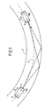
- FIG. 1 schematically shows two mobiles (M1) and (M2) moving one behind the other inside a tunnel (T), in the transport direction illustrated by the arrows (F). ; it is for example two trains following each other in a railway tunnel.
- Each mobile (M1), (M2) is equipped at the front with an interrogator device (I) and at the rear of an answering device (R).
- the interrogator device (I) of the mobile device M1 generally makes it possible to send a microwave interrogation signal to the answering device (R) of the mobile (M2).
- the interrogation and response signals are transmitted and received by means of directional antennas, the walls of the tunnel (T) acting as waveguides.
- the signal received by a mobile is the sum of the waves reflected on the walls of the tunnel.
- the distance that is calculated by the interrogator device of the mobile (M1) will correspond to an estimate of the curvilinear distance along the curve (C) schematizing the actual path of the mobiles (M1) and (M2).
- the invention is not limited to guided wave propagation, but it can also be implemented with freely propagating interrogation and response signals.
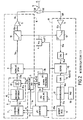
- the generator 6 of pseudo-random interrogation sequences is for example made in the usual manner and known in the form of a shift register looped back on itself.
- the configuration of such a shift register generator is fixed case by case, and in a manner known per se, according to the pseudo-random bit sequence to be generated, and is usually defined by a polynomial.
- the encoding means 8 comprise a first encoder circuit 8 'producing in a known way a differential encoding of the binary information (signal 7 a ) delivered by the generator 7, followed by a second encoder circuit 8''performing a logical (exclusive OR) summation of each bit the signal 8 'is encoded in differential mode, with a sequence of pseudo-random interrogation (PN1) delivered by the generator 6.
- the modulation means 9 are designed to perform the usual manner a phase modulation of the carrier (clock signal 3 b ) from the modulation signal 8 has spread, and for example a DPSK modulation.
- the pseudo-random response sequence (PN2) stored in memory in the form of a binary code in the register 18, is orthogonal to the pseudo-random interrogation sequence (PN1) .
- the electronic architecture of the answering device (R) is similar to that of the interrogator device (I) of FIG. 2.
- the elements of the answering device (R) which differ from those set in in the interrogator device (I) previously described will be explained.
- the transmitter module (RE) of the answering device (R) differs from the transmitter module (IE) of the interrogator device (I) of FIG. 2 mainly by the implementation of a generator 6 'which is designed to generate pseudorandom response sequences (PN2) orthogonal to the pseudo-random interrogation sequences (PN1).
- a generator 6 ' which is designed to generate pseudorandom response sequences (PN2) orthogonal to the pseudo-random interrogation sequences (PN1).
- the receiver module (RR) of the answering device (R) differs from the receiver module (IR) of the interrogator device (I) of FIG. 2 mainly by the implementation of a register 18 'in which is stored the binary code corresponding to a pseudo-random interrogation sequence (PN1), and by the implementation of a circuit 20 (known per se) of data formatting, whose function is to restore under binary form the received message (synchronization frame and data frame) from the correlation peaks of the signal 17 a .
- PN1 pseudo-random interrogation sequence
- the circuit 20 performs a binary coding of the correlation peaks, a positive peak corresponding to a bit equal to 1, and a negative peak corresponding to a bit equal to 0, and this binary information is decoded in differential mode, knowing that the emission was carried out a differential encoding of the binary information (encoder circuit 8 ').
- the binary information reconstituted by the circuit 20 is transmitted progressively to the microprocessor of the processing unit 1.
- the microprocessor is programmed to detect that all the binary information of a message (synchronization frame and data) have been sent to it. transmitted, and for once this detection carried out, transmit this binary information to the generator 7 via the signal 1 c , and clocking with the help of the clock signal 1 b the retransmission of the received message (synchronization frame and data frame).
- the interrogator device (I) and the answering device (R) are constantly in reception mode (switches 5 in position (b)).
- the mobile (M1) wishes to measure the distance separating it from the mobile (M2) (FIG. 1)
- its interrogator device (I) switches to transmission mode and sends via the antenna (A) to the responder device (R) of the mobile device (M2) which is in reception mode, an interrogation signal (SI) containing a message (synchronization frame and data frame) which is delivered by the generator 7 of the transmitter module (IE) of the interrogator (I).
- the bits of a message are delivered in series (signal 7 a ) by the generator 7 of the transmitter module (IE) on the rising edge of the clock signal 1 b .
- the first bit of the message which corresponds to the first bit of the synchronization frame, is delivered by the generator 7 at the instant (t0).
- the first bit of the data frame is delivered at time (t1).
- SI microwave signal of interrogation
- DPSK modulation phase modulation
- the microprocessor of the processing unit 1 of the transmitter module (IE) is programmed to, in parallel with sending the message, incrementing a counter internal (initially zero), on each clock signal rising edge 3a, after the transmission of the first bit of the data frame (time t1 in the timing diagram of Figure 4).
- the interrogator device (I) of the mobile (M1) switches to receive mode (switch 5 in position (b)).
- the interrogation signal (SI) is received by the receiver module (RE) of the mobile answering device (M2), which is in reception mode.
- the local oscillator 4 is locked in phase with the clock signal 3 b, that is to say with the main local oscillator 2.
- the received signal is demodulated (15 a signal ) and then digitized (signal 16 a ), and the binary information is correlated with the pseudo-random interrogation code (PN1) stored in the register 18 '.
- the correlation signal 17a output by the correlation filter 17 comprises a series of correlation peaks.
- the circuit 20 reconstitutes, for the microprocessor of the processing unit 1, the received binary message.
- the answering device After reception by the microprocessor of this binary message, the answering device switches to transmit mode (switch 5 in position (a)), and this reconstituted binary message is returned by the transmitter module (RE), in the form of the microwave response signal (SR) being encoded with the pseudo-random response sequences (PN2) delivered by the generator 6 '.
- the transfer time between the reception module (RR) and the transmission module (RE) of an answering device (R) After transmission of the response signal (SR), the answering device (R) switches back to receive mode, and is waiting for the next interrogation signal (SI).
- the coded response signal (SR) (PN2) which has been returned by the answering device (R) is received by the receiving module (RE) of the interrogator device (I) which is in reception mode.
- the received signal is demodulated (signal a ) then digitized (signal 16 a ), and the binary information is correlated with the pseudo-random response code (PN2) stored in register 18.
- the microprocessor of the processing unit 1 stops its internal counter.
- This detection is performed by the circuit 19, which after detection of the first peak (p) in the correlation signal 17 has ( Figure 4) corresponding to the first bit of the data frame, generates the detection signal 19a to the microprocessor of the processing unit 1 in the form of a slot or a pulse.
- the current value (N) of the microprocessor counter of the processing unit 1, after stopping, is representative of the propagation time of the interrogation (SI) and response (SR) signals between the mobiles (M1) and (M2 ), and hence of the distance separating the two mobiles.
- the value (th) corresponds to the period of the signal clock 3 a .
- the value of the transfer time (dt) of the information in the answering machine (R) is a constant value which will be estimated on a case by case basis.
- the implementation of a coding of the information of the interrogation (SI) and response (SR) signals according to the known direct sequence spread spectrum technique by means of pseudorandom sequences makes it possible to benefit from all the advantages known from this technique.
- the accuracy of the distance measurement is related to the frequency (FH) and is even higher than the figure (FH) is high.
- the signal-to-noise ratio after processing is all the more important as the length of the pseudorandom sequences (PN1) and (PN2) is important. It is thus possible to perform measurements over long distances (greater than one kilometer) with good accuracy.
- Another preponderant and specific advantage of the invention stems from the implementation of orthogonal pseudo-random sequences (PN1) and (PN2).
- SI interrogation signal
- PN1 pseudo-random interrogation sequence
- A antenna
- the digital signal 16 has corresponding to it to the input of the correlation filter 17 being encoded with a pseudo-random sequence (PN1) orthogonal to the pseudo sequence response-random (PN2) stored in memory in the register 18, the correlation filter 17 outputs a correlation signal 17 is free from the correlation peak, and resulting in noise whose level is significantly below the threshold of detection is used by the peak detection means 19.
- the signals received by the interrogating mobile the signals (SR) actually sent by the answering mobile and which must be used by the interrogator for the distance measurement, and secondly the unwanted signals not coded with the response code (PN2), which are automatically ignored by the interrogator during the distance measurement.
- the message in particular the data frame
- the answering device could send a different message (in particular a data frame).
- a data recovery circuit is preferably provided at the interrogator device that interfaces the correlator filter 17 and the microprocessor of the processing unit 1.
- the data frames of the messages exchanged between the two mobiles (M1) and (M2) can be used for the exchange of information between mobiles such as for example the identification, the speed of each mobile, etc.
- the interrogator device (I) and the answering device (R) each comprise a transmitting antenna (A) and a receiving antenna (A ') which are distinct from one another (unlike the first variant previously described).
- the transmitter module (IE) of the interrogator device (I) comprises a generator 7 'whose function is to generate at the output (signal 7' a ) bits at 1 in series at the rate set by the clock signal 1b . Accordingly, when the authorization one signal issued by the microprocessor of the processing unit 1 is active, the modulation signal has 8 output of the encoding means 8 corresponds to the pseudo-random interrogation sequence ( PN1) not modulated by data contrary to the first embodiment of Figure 2.
- the transmitter module (IE) comprises a second generator 6 '' of pseudo-random sequences (PN3) orthogonal to the pseudo-random interrogation sequences (PN1).
- This generator 6 '' is clocked by the same clock signal 3 has the generator 6 (PN1 sequences).
- the digital signal 6 '' a (PN3 sequences) delivered by the second generator 6 "is added to the signal 6a (PN1 sequences) delivered by the generator 6 (logic addition / logic gate” OR "21).
- the generators 6 and 6 '' are activated, the signal 21a resulting from this logical addition form over time a series of sequences of pseudo-random response (PN2) which are synchronous with successive sequences of pseudo-random interrogation (PN1) delivered by the 6.
- PN3 a pseudo-random sequence
- PN2 the pseudo-random response sequence resulting from the sum of the sequences (PN1) and (PN3) is also orthogonal to the pseudo-random interrogation sequence (PN1).
- the pseudo-random sequences (PN1) and (PN3) delivered by the generators 6 and 6 '' can be generated respectively from the polynomials mentioned above for the pseudo-random sequences (PN1) and (PN2) ) in the context of the first variant embodiment of FIGS. 2 to 4.
- the signal 21a (PN2 sequences) is reversed by means of a logic inverter 22, 22 outputting a signal a (pseudo-random sequences inverted / PN2).
- This signal 22a is used to modulate phase a pure carrier corresponding to the main clock signal 2 a .
- This modulation (modulation means 23 in FIG. 5) is of the same type as that produced by the modulation means 9, using the modulation signal 8 a , that is to say in the example illustrated a DPSK phase modulation.
- the modulated signal 23 a is added (block 24 / analog addition) to the demodulated signal delivered at the output of the demodulation means 15 of the receiver module (IR).
- This addition is done in parallel on the phase (I) and quadrature (Q) components of the signal a .
- the addition with the in-phase component (I) is carried out with the signal 23 a .
- the addition with the quadrature component (Q) is performed with a signal (not shown) obtained by phase shift of ⁇ / 2 of the signal 23 a .
- the analog signal 24 is obtained from this addition is converted into a digital signal 16 has the analog / digital converter 16.
- the correlation signal 17 is derived from the correlation filter 17 of the receiver module (IR) is received by the microprocessor of the processing unit 1 in parallel to two distinct inputs. One (+) of its two inputs is associated with a predetermined positive detection threshold, and the other input (-) is associated with a predetermined negative detection threshold.
- the responder device (R) contains the same generators 7 'and 6 "(PN3 code) as well as the same means for logically summing the signals 6' 'a (code PN3) and 6a (PN1) (logic gate code 'OR' 21) for the interrogator device (I) of Figure 5.
- the signal 21a resulting from the logical sum signal 6 a and 6 '' and a corresponding pseudo-random response sequences (PN2) is used to modulate the carrier 3 c (encoding means 8 and modulation 9) for transmitting the response signal (SR).
- responder device (R) of Figure 6 sets out further detection means 25 which are designed to detect correlation peaks in the correlation signal 17, by comparing the correlation signal 17a with a predetermined threshold, and which, on detection of the first peak in the correlation signal 17 is generated to the microprocessor of the processing unit 1 a detection signal 19a, for example in the form of a slot or of a pulse .
- the microprocessor of the processing unit 1 of the answering device activates the authorization signal 1 a .
- the generator 6 and 6 "issue in parallel a series of (m) successive pseudorandom sequences (PN1) and (PN3) (signal 6 a and 6 '' a). In the particular example of FIG. 7, five pseudo-random sequences are generated afterwards.
- the interrogation signal (SI) coded by the series of pseudo-random interrogation sequences (PN1) is transmitted by the interrogator device (I) of the mobile (M1) and then received at the instant t1 by the answering device (R ) of the mobile (M2).
- the responder device (R), after detection of the first peak in the correlation signal 17a (detector 25) refers to the time (t1 + dt) a response signal (SR) encoded by a series of (m) pseudo-sequences - random response (PN2).
- the coded response signal (SR) (PN2) is received by the interrogator device of the mobile (M1) at the instant (2t1 + dt).
- the output of the correlator 17 filter we obtain a correlation signal 17a consists of a succession of positive and negative peaks alternately.
- the positive peaks correspond to the correlation of the pseudo-random sequences (PN2) received successively in time by the interrogator device (I) (response signal SR) with the sequence code (PN2) stored in the register 18.
- the negative peaks correspond to the correlation, with the code (PN2) stored in the register 18, inverted response pseudo-random sequences [/ PN2 (t0), / PN2 (t0 + tb), / PN2 (t0 + 2tb), / PN2 (t0 + 3tb) / PN2 ( t0 + 4 (ps)] which are successively generated locally by the interrogator device (signal 22 a) parallel to the transmission of the interrogation signal (SI) code (PN1).
- SI interrogation signal
- the microprocessor of the interrogator device processing unit (I) is programmed to perform parallel detection of the positive peaks by comparing the correlation signal 17 received on its input (+) with a threshold (S +) predetermined positive, and detection of the negative peaks by comparison of the correlation signal 17a received on its input (-) with a predetermined negative threshold (S-).
- Each distance d i corresponds to an estimate of the distance (D) separating the mobile (M1) from the mobile (M2).
- the microprocessor of the processing unit 1 of the interrogator device (I) is advantageously programmed to calculate, from the set of distances d i , an estimate of the distance (D), for example by averaging the set of values d i .
- the second variant which has just been described advantageously makes it possible to rapidly calculate a precise distance between the mobiles (M1) and (M2). This accuracy increases with the number (m) of pseudorandom sequences generated to encode an interrogation signal (SI).
- the second variant described with reference to Figures 5 to 7 also has two additional benefits deriving from the presence of signs opposite peaks in the correlation signal 17a of the responder device to characterize the one hand the transmission times of a pseudo-random interrogation sequence (PN1) (negative peaks) and secondly the times of reception by the interrogator device of a pseudo-random response sequence (PN2).
- PN1 pseudo-random interrogation sequence
- PN2 pseudo-random response sequence
- the first advantage is the possibility of implementing detection thresholds (S +) and (S-) which can differ in absolute value, and which can therefore be perfectly adapted to the level of the peaks, knowing that the positive peaks in the variant of Figures 5 to 7 will have a lower maximum value than the negative peaks.
- the second advantage is that the length of the pseudo-random sequences can be chosen independently of the desired range.
- the invention is not limited to the two variant embodiments which have just been described with reference to FIGS. 1 to 7, but extends to any method or system for calculating the distance between two objects implementing to code respectively the interrogation (SI) and response (SR) signals, pseudo-random interrogation (PN1) and response (PN2) sequences which are orthogonal.
- SI interrogation
- SR response
- PN1 pseudo-random interrogation
- PN2 pseudo-random interrogation sequences which are orthogonal.
- pseudo-random sequence is not limited to the notion of generating polynomials (that is to say in practice to the implementation of a register with a shift loopback on itself to generate the pseudo-random sequence), but extends to any sequence (or code) having the same orthogonality properties as the pseudo-random sequences generated using polynomials, and able to be implemented in the direct sequence spread spectrum coding technique.
- pseudorandom sequences of interrogation and response it is conceivable, for example, to use Barker codes.
- the second embodiment described with reference to FIGS. 5 to 7 can be improved so as to allow the exchange of information between mobiles (M1) and (M2).
- PN1 pseudo-random interrogation sequences
- PN2 pseudo-random response sequences
Landscapes
- Engineering & Computer Science (AREA)
- Radar, Positioning & Navigation (AREA)
- Remote Sensing (AREA)
- Computer Networks & Wireless Communication (AREA)
- Physics & Mathematics (AREA)
- General Physics & Mathematics (AREA)
- Radar Systems Or Details Thereof (AREA)
- Measurement Of Optical Distance (AREA)
Claims (8)
- Verfahren zum Messen der Entfernung zwischen einem abfragenden Objekt (M1/I) und einem antwortenden Objekt (M2/R), wonach durch das abfragende Objekt ein Abfragesignal (SI) zu dem antwortenden Objekt ausgesandt wird und durch das antwortende Objekt - nach dem Empfang dieses Abfragesignals - ein Antwortsignal (SR) zu dem abfragenden Objekt ausgesandt wird, und die Entfernung zwischen dem abfragenden Objekt und dem antwortenden Objekt anhand einer Messung der Ausbreitungszeit des Abfragesignals (SI) und des Antwortsignals (SR) zwischen den zwei Objekten berechnet wird, wobei das Abfragesignal (SI) dadurch erhalten wird, daß eine Trägerwelle mit einem ersten Modulationssignal (8a) moduliert wird, und das Antwortsignal (SR) dadurch erhalten wird, daß eine Trägerwelle mit einem zweiten Modulationssignal (8a) moduliert wird, dadurch gekennzeichnet, daß:- das genannte erste Modulationssignal (8a) mittels einer oder mehrerer pseudozufälliger Abfragefolgen (PN1) erzeugt wird,- das genannte zweite Modulationssignal (8a) mittels einer oder mehrerer pseudozufälliger Antwortfolgen (PN2) erzeugt wird, die zu den pseudozufälligen Abfragefolgen (PN1) orthogonal sind,- für die Entfernungsmessung eine Korrelation des durch das abfragende Objekt (M1/I) empfangenen Signals mit dem für eine pseudozufällige Antwortfolge (PN2) charakteristischen Code durchgeführt wird.
- Verfahren nach Anspruch 1, dadurch gekennzeichnet, daß das erste Modulationssignal (8a) [abfragendes Objekt (M1/I)] dadurch erzeugt wird, daß ein erster Block von Binärdaten nach der Direct Sequence Spread Spectrum (DSSS)-Technik oder mittels pseudozufälliger Abfragefolgen (PN1) codiert wird, daß das zweite Modulationssignal (8a) [antwortendes Objekt (M2/R)] dadurch erzeugt wird, daß ein zweiter Block von Binärdaten nach der Direct Sequence Spread Spectrum (DSSS)-Technik oder mittels pseudozufälliger Antwortfolgen (PN2) codiert wird, und daß die Messung der Ausbreitungszeit der Signale zwischen den zwei Objekten - für die Berechnung der Entfernung - dadurch vollzogen wird, daß ein Korrelationspeak (p) in dem Korrelationssignal (17a) erfaßt wird, das aus der Korrelation des durch das abfragende Objekt empfangenen Signals mit dem für die pseudozufällige Antwortfolge (PN2) charakteristischen Code hervorgegangen ist.
- Verfahren nach Anspruch 1, dadurch gekennzeichnet, daß:- im Bereich des abfragenden Objekts (M1/I) eine Reihe von (m) pseudozufälligen Abfragefolgen (PN1) erzeugt wird [wobei m eine Ganzzahl größer oder gleich 1 ist], um das Abfragesignal (Sl) zu codieren, und- im Bereich des antwortenden Objekts (M2/R) eine Reihe von (m) pseudozufälligen Antwortfolgen (PN2) erzeugt wird, um das Antwortsignal (SR) zu codieren.
- Verfahren nach Anspruch 3, dadurch gekennzeichnet, daß im Bereich des abfragenden Objekts (M1/I), parallel zur Sendung des Abfragesignals (SI), synchron mit der Reihe von (m) pseudozufälligen Abfragefolgen (PN1), eine Reihe von (m) pseudozufälligen Folgen (/PN2) generiert wird, die im Vergleich zu den pseudozufälligen Antwortfolgen (PN2) umgekehrt sind, und daß die Messung der Ausbreitungszeit der Signale zwischen den zwei Objekten, für die Berechnung der Entfernung, dadurch vollzogen wird, daß:- anhand des durch das abfragende Objekt (M1/I) empfangenen Antwortsignals (SR) und der Reihe von (m) umgekehrten pseudozufälligen Antwortfolgen (/PN2) ein Korrelationssignal (17a) mit negativen und positiven Korrelationspeaks erzeugt wird, wobei jedes negative Peak aus der Korrelation einer umgekehrten pseudozufälligen Antwortfolge mit dem für die pseudozufällige Abfragfolge (PN2) charakteristischen Code hervorgegangen ist und wobei jedes positive Peak aus der Korrelation einer pseudozufälligen Folge des durch das abfragende Objekt (M1/K) empfangenen Antwortsignals (SR) mit dem für die pseudozufällige Abfragefolge (PN2) charakteristischen Code hervorgegangen ist,- und dadurch, daß jeder Zeitabstand (δti) gemessen wird, welcher ein negatives Peak und das auf dieses zeitlich folgende erste positive Peak voneinander trennt.
- System zum Messen der Entfernung zwischen einem abfragenden Objekt (M1/I) und einem antwortenden Objekt (M2/R), bei dem jedes Objekt einerseits mit einem Sendemodul, das Mittel zur Modulation einer Trägerwelle umfaßt und das das Senden eines Signals an das andere Objekt ermöglicht, und andererseits mit einem Empfängermodul ausgestattet ist, das geeignet ist, ein durch das Sendemodul des anderen Objekts gesendetes Signal zu empfangen, dadurch gekennzeichnet, daß:- das Sendemodul (lE) des abfragenden Objekts (M1/I) einen Generator (6) für pseudozufällige Abfragefolgen (PN1) umfaßt und die Modulationsmittel (9) dieses Sendemoduls ausgelegt sind, um eine Trägerwelle (3b) anhand der durch diesen Generator (6) gelieferten pseudozufälligen Abfragefolgen (PN1) zu modulieren,- das Sendemodul (RE) des antwortenden Objekts (M2/R) einen Generator für pseudozufällige Antwortfolgen (PN2) umfaßt, die zu den pseudozufälligen Abfragefolgen (PN1) orthogonal sind, und die Modulationsmittel (9) dieses Sendemoduls ausgelegt sind, um eine Trägerwelle (3b) anhand der durch diesen Generator gelieferten pseudozufälligen Antwortsequenzen (PN2) zu modulieren,- das Empfängermodul (RR) des antwortenden Objekts (M2/R) ein Register (18'), in dem der für eine pseudozufällige Abfragefolge (PN1) charakteristische Code gespeichert ist, sowie Mittel (17) zur Korrelation des durch das antwortende Objekt (M2/R) empfangenen Signals mit dem in diesem Register (18') gespeicherten Code (PN1) umfaßt,- das Empfängermodul (IR) des abfragenden Objekts (M1/I) ein Register (18), in dem der für eine pseudozufällige Antwortfolge (PN2) charakteristische Code gespeichert ist, sowie Mittel (17) zur Korrelation des durch das abfragende Objekt (M1/I) empfangenen Signals mit dem in diesem Register (18) gespeicherten Code (PN2) umfaßt,- das abfragende Objekt (M1/I) Mittel (1) zur Berechnung der Entfernung zwischen dem abfragenden Objekt (M1/I) und dem antwortenden Objekt (M2/R) anhand einer Erfassung von Korrelationspeaks in dem aus den Korrelationsmitteln (17) hervorgegangenen Korrelationssignal (17a) umfaßt.
- System nach Anspruch 5, dadurch gekennzeichnet, daß die Entfernungsberechnungsmittel (1) des abfragenden Objekts (M1/I) einen Zähler verwenden, der bei Senden des Abfragesignals (SI) ausgelöst wird und der bei Erfassung eines Korrelationspeaks (p) in dem Korrelationssignal (17a) angehalten wird.
- System nach Anspruch 5, dadurch gekennzeichnet, daß das Sendemodul (lE) der Abfragevorrichtung (M1/I) Mittel (6", 21, 22) umfaßt, die ausgelegt sind, um pseudozufällige Folgen (/PN2) zu erzeugen, die im Vergleich zu den pseudozufälligen Antwortfolgen (PN2) umgekehrt und mit den durch den Generator (6) erzeugten pseudozufälligen Abfragefolgen (PN1) synchron sind, daß die Korrelationsmittel (17) des Sendemoduls (IE) der Abfragevorrichtung (M1/I) ebenfalls ausgelegt sind, um eine Korrelation einer jeden lokal generierten, umgekehrten pseudozufälligen Folge (/PN2) mit dem in dem Register (18) gespeicherten Antwortcode (PN2) durchzuführen, und daß die Mittel (1) zur Entfernungsberechnung ausgelegt sind, um eine Erfassung der positiven Peaks und der negativen Peaks in dem durch die Korrelationsmittel (17) des Empfängermoduls (IR) des abfragenden Objekts (M1/I) gelieferten Korrelationssignal (17a) durchzuführen.
- Anwendung des Verfahrens von einem der Ansprüche 1 bis 4 auf die Messung der Entfernung zwischen sich auf einer Strecke folgenden Fahrzeugen (M1. M2) und insbesondere zwischen Eisenbahnwagenzügen, wobei jedes Fahrzeug (M1, M2) vorne mit einer Abfragevorrichtung (I) und hinten mit einer Antwortvorrichtung (R) ausgestattet ist, wobei die Abfragevorrichtung (I) eines Fahrzeugs (M1) vorgesehen ist, um mit der Antwortvorrichtung (R) des vor ihm fahrenden Fahrzeugs (M2) zu kommunizieren und um eine Entfernungsberechnung nach einem der Ansprüche 1 bis 4 zu ermöglichen.
Applications Claiming Priority (2)
| Application Number | Priority Date | Filing Date | Title |
|---|---|---|---|
| FR9906893A FR2794245B1 (fr) | 1999-05-26 | 1999-05-26 | Procede et systeme de mesure de la distance entre deux objets mettant en oeuvre des sequences pseudo-aleatoires orthogonales |
| FR9906893 | 1999-05-26 |
Publications (2)
| Publication Number | Publication Date |
|---|---|
| EP1055940A1 EP1055940A1 (de) | 2000-11-29 |
| EP1055940B1 true EP1055940B1 (de) | 2006-09-20 |
Family
ID=9546226
Family Applications (1)
| Application Number | Title | Priority Date | Filing Date |
|---|---|---|---|
| EP00490019A Expired - Lifetime EP1055940B1 (de) | 1999-05-26 | 2000-05-25 | Verfahren und System zur Messung der Entfernung zwischen zwei Objekten mittels aufeinanderfolgender orthogonaler Pseudozufallszahlen |
Country Status (4)
| Country | Link |
|---|---|
| EP (1) | EP1055940B1 (de) |
| AT (1) | ATE340364T1 (de) |
| DE (1) | DE60030803T2 (de) |
| FR (1) | FR2794245B1 (de) |
Cited By (1)
| Publication number | Priority date | Publication date | Assignee | Title |
|---|---|---|---|---|
| KR101369202B1 (ko) | 2010-06-15 | 2014-03-05 | 에코스솔루션(주) | 직접시퀀스초광대역 방식의 고분해능 단거리 레이더장치 |
Families Citing this family (2)
| Publication number | Priority date | Publication date | Assignee | Title |
|---|---|---|---|---|
| GB0228808D0 (en) | 2002-12-11 | 2003-01-15 | Koninkl Philips Electronics Nv | Method and apparatus for measuring distance |
| CN116699506B (zh) * | 2023-08-02 | 2023-10-13 | 烟台初心航空科技有限公司 | 近程无线电导航系统测距信标台应答信号产生装置 |
Family Cites Families (6)
| Publication number | Priority date | Publication date | Assignee | Title |
|---|---|---|---|---|
| US3934251A (en) * | 1974-11-07 | 1976-01-20 | The Bendix Corporation | Automatic t0 control for use in airborne DME system |
| FR2644919B1 (fr) * | 1989-03-21 | 1991-05-31 | Dassault Electronique | Procede et dispositif pour l'aide a la circulation de vehicules terrestres |
| DE4419893A1 (de) * | 1994-06-07 | 1995-12-14 | Siemens Ag | Abstandswarnsystem für Fahrzeuge |
| CA2127160A1 (en) * | 1994-06-30 | 1995-12-31 | Shahrokh Ehsani-Nategh | System and method for radar-vision for vehicles in traffic |
| US5550549A (en) * | 1995-02-28 | 1996-08-27 | Harris Corporation | Transponder system and method |
| US6107959A (en) * | 1996-09-30 | 2000-08-22 | Qualcomm Incorporated | Positioning determination using one low-Earth orbit satellite |
-
1999
- 1999-05-26 FR FR9906893A patent/FR2794245B1/fr not_active Expired - Fee Related
-
2000
- 2000-05-25 EP EP00490019A patent/EP1055940B1/de not_active Expired - Lifetime
- 2000-05-25 AT AT00490019T patent/ATE340364T1/de active
- 2000-05-25 DE DE60030803T patent/DE60030803T2/de not_active Expired - Lifetime
Cited By (1)
| Publication number | Priority date | Publication date | Assignee | Title |
|---|---|---|---|---|
| KR101369202B1 (ko) | 2010-06-15 | 2014-03-05 | 에코스솔루션(주) | 직접시퀀스초광대역 방식의 고분해능 단거리 레이더장치 |
Also Published As
| Publication number | Publication date |
|---|---|
| ATE340364T1 (de) | 2006-10-15 |
| FR2794245B1 (fr) | 2003-06-20 |
| DE60030803D1 (de) | 2006-11-02 |
| FR2794245A1 (fr) | 2000-12-01 |
| EP1055940A1 (de) | 2000-11-29 |
| DE60030803T2 (de) | 2007-09-13 |
Similar Documents
| Publication | Publication Date | Title |
|---|---|---|
| US7982861B2 (en) | Time delay and distance measurement | |
| CN113156405A (zh) | Fmcw激光雷达多源串扰解耦方法、fmcw激光雷达及雷达系统 | |
| JP6696968B2 (ja) | 位相符号化データチャネルを有するfmcwレーダ | |
| Béchadergue et al. | Simultaneous visible light communication and distance measurement based on the automotive lighting | |
| FR2642922A1 (fr) | Dispositif de communication sur spectre disperse | |
| EP0658024B1 (de) | Ein drahtloses lokales Netzwerk | |
| EP0389325B1 (de) | Verfahren und Gerät zur Hilfe des Landfahrzeugverkehrs | |
| US8295323B2 (en) | Synchronization for frequency hopping (FH) communication | |
| EP1706757B1 (de) | Verfahren und empfängervorrichtung zur drahtlosen datenkommunikation mit ultrabreitbandigen zeitcodierten signalen | |
| EP1298811A1 (de) | Verfahren und Gerät zur Impulsdetektierung in einem empfangenen Ultrabreitbandsignal | |
| CN1117315A (zh) | 短脉冲单音测距处理系统和方法 | |
| WO1996042137A1 (en) | Best-of-m pulse position modulation detector | |
| JPH05256936A (ja) | 車載レーダ装置 | |
| EP2790035B1 (de) | Verfahren und Vorrichtung zur Kompression eines Breitband-Funk-Navigationssignals, entsprechendes Verfahren und entsprechende Vorrichtung zur Berechnung der Korrelationsfunktion des Streuungskodes dieses komprimierten Signals | |
| WO2002048735A1 (fr) | Radar large bande et modulateur, notamment pour commuter des ondes hyperfrequence sur une tres courte duree | |
| EP1055940A1 (de) | Verfahren und System zur Messung der Entfernung zwischen zwei Objekten mittels aufeinanderfolgender orthogonaler Pseudozufallszahlen | |
| FR2738968A1 (fr) | Procede de localisation d'un emetteur-recepteur de paquets de donnees et emetteur-recepteur mettant en oeuvre ce procede | |
| EP2506444B1 (de) | Verfahren und Vorrichtung zur Integration von Ultrabreitbandsignalen | |
| EP2920604B1 (de) | System und verfahren zum funk-tagging von funksendern | |
| WO2005038487A1 (fr) | Procédé et dispositif de filtrage d'un signal vidéo reçu par un radar secondaire, notamment pour éliminer les réponses mode s | |
| EP1058402B1 (de) | Verfahren zur Verarbeitung eines Impulssignals mit einer adaptiven Schwelle und entsprechender Empfänger | |
| EP0994580B1 (de) | Übertragungsverfahren in einem Funkkommunikationssystem mit Vielfachzugriff | |
| WO2003019481A1 (fr) | Procede d'autorisation de deverrouillage et/ou de demarrage d'un vehicule automobile et dispositif associe | |
| EP3458875A1 (de) | Optisches telemetriesystem | |
| FR3124339A1 (fr) | Méthode d’estimation de caractéristiques d’un signal ultra large bande impulsionnel émis par plusieurs antennes |
Legal Events
| Date | Code | Title | Description |
|---|---|---|---|
| PUAI | Public reference made under article 153(3) epc to a published international application that has entered the european phase |
Free format text: ORIGINAL CODE: 0009012 |
|
| AK | Designated contracting states |
Kind code of ref document: A1 Designated state(s): AT BE CH CY DE DK ES FI FR GB GR IE IT LI LU MC NL PT SE |
|
| AX | Request for extension of the european patent |
Free format text: AL;LT;LV;MK;RO;SI |
|
| 17P | Request for examination filed |
Effective date: 20010314 |
|
| AKX | Designation fees paid |
Free format text: AT BE CH CY DE DK ES FI FR GB GR IE IT LI LU MC NL PT SE |
|
| 17Q | First examination report despatched |
Effective date: 20040902 |
|
| GRAP | Despatch of communication of intention to grant a patent |
Free format text: ORIGINAL CODE: EPIDOSNIGR1 |
|
| RTI1 | Title (correction) |
Free format text: METHOD AND SYSTEM OF MEASURING THE DISTANCE BETWEEN TWO OBJECTS EMPLOYING ORTHOGONAL PSEUDO RANDOM SEQUENCES |
|
| GRAS | Grant fee paid |
Free format text: ORIGINAL CODE: EPIDOSNIGR3 |
|
| GRAA | (expected) grant |
Free format text: ORIGINAL CODE: 0009210 |
|
| AK | Designated contracting states |
Kind code of ref document: B1 Designated state(s): AT BE CH CY DE DK ES FI FR GB GR IE IT LI LU MC NL PT SE |
|
| PG25 | Lapsed in a contracting state [announced via postgrant information from national office to epo] |
Ref country code: FI Free format text: LAPSE BECAUSE OF FAILURE TO SUBMIT A TRANSLATION OF THE DESCRIPTION OR TO PAY THE FEE WITHIN THE PRESCRIBED TIME-LIMIT Effective date: 20060920 Ref country code: NL Free format text: LAPSE BECAUSE OF FAILURE TO SUBMIT A TRANSLATION OF THE DESCRIPTION OR TO PAY THE FEE WITHIN THE PRESCRIBED TIME-LIMIT Effective date: 20060920 Ref country code: IT Free format text: LAPSE BECAUSE OF FAILURE TO SUBMIT A TRANSLATION OF THE DESCRIPTION OR TO PAY THE FEE WITHIN THE PRESCRIBED TIME-LIMIT;WARNING: LAPSES OF ITALIAN PATENTS WITH EFFECTIVE DATE BEFORE 2007 MAY HAVE OCCURRED AT ANY TIME BEFORE 2007. THE CORRECT EFFECTIVE DATE MAY BE DIFFERENT FROM THE ONE RECORDED. Effective date: 20060920 |
|
| REG | Reference to a national code |
Ref country code: GB Ref legal event code: FG4D Free format text: NOT ENGLISH |
|
| REG | Reference to a national code |
Ref country code: CH Ref legal event code: EP |
|
| REG | Reference to a national code |
Ref country code: IE Ref legal event code: FG4D Free format text: LANGUAGE OF EP DOCUMENT: FRENCH |
|
| REF | Corresponds to: |
Ref document number: 60030803 Country of ref document: DE Date of ref document: 20061102 Kind code of ref document: P |
|
| PG25 | Lapsed in a contracting state [announced via postgrant information from national office to epo] |
Ref country code: SE Free format text: LAPSE BECAUSE OF FAILURE TO SUBMIT A TRANSLATION OF THE DESCRIPTION OR TO PAY THE FEE WITHIN THE PRESCRIBED TIME-LIMIT Effective date: 20061220 Ref country code: DK Free format text: LAPSE BECAUSE OF FAILURE TO SUBMIT A TRANSLATION OF THE DESCRIPTION OR TO PAY THE FEE WITHIN THE PRESCRIBED TIME-LIMIT Effective date: 20061220 |
|
| PG25 | Lapsed in a contracting state [announced via postgrant information from national office to epo] |
Ref country code: ES Free format text: LAPSE BECAUSE OF FAILURE TO SUBMIT A TRANSLATION OF THE DESCRIPTION OR TO PAY THE FEE WITHIN THE PRESCRIBED TIME-LIMIT Effective date: 20061231 |
|
| GBT | Gb: translation of ep patent filed (gb section 77(6)(a)/1977) |
Effective date: 20061229 |
|
| NLV1 | Nl: lapsed or annulled due to failure to fulfill the requirements of art. 29p and 29m of the patents act | ||
| PG25 | Lapsed in a contracting state [announced via postgrant information from national office to epo] |
Ref country code: PT Free format text: LAPSE BECAUSE OF FAILURE TO SUBMIT A TRANSLATION OF THE DESCRIPTION OR TO PAY THE FEE WITHIN THE PRESCRIBED TIME-LIMIT Effective date: 20070312 |
|
| PLBE | No opposition filed within time limit |
Free format text: ORIGINAL CODE: 0009261 |
|
| STAA | Information on the status of an ep patent application or granted ep patent |
Free format text: STATUS: NO OPPOSITION FILED WITHIN TIME LIMIT |
|
| 26N | No opposition filed |
Effective date: 20070621 |
|
| PG25 | Lapsed in a contracting state [announced via postgrant information from national office to epo] |
Ref country code: MC Free format text: LAPSE BECAUSE OF NON-PAYMENT OF DUE FEES Effective date: 20070531 |
|
| PG25 | Lapsed in a contracting state [announced via postgrant information from national office to epo] |
Ref country code: GR Free format text: LAPSE BECAUSE OF FAILURE TO SUBMIT A TRANSLATION OF THE DESCRIPTION OR TO PAY THE FEE WITHIN THE PRESCRIBED TIME-LIMIT Effective date: 20061221 |
|
| PG25 | Lapsed in a contracting state [announced via postgrant information from national office to epo] |
Ref country code: CY Free format text: LAPSE BECAUSE OF FAILURE TO SUBMIT A TRANSLATION OF THE DESCRIPTION OR TO PAY THE FEE WITHIN THE PRESCRIBED TIME-LIMIT Effective date: 20060920 Ref country code: LU Free format text: LAPSE BECAUSE OF NON-PAYMENT OF DUE FEES Effective date: 20070525 |
|
| REG | Reference to a national code |
Ref country code: CH Ref legal event code: PFA Owner name: UNIVERSITE DES SCIENCES ET TECHNOLOGIES DE LILLE Free format text: UNIVERSITE DES SCIENCES ET TECHNOLOGIES DE LILLE#CITE SCIENTIFIQUE#59655 VILLENEUVE-D'ASCQ CEDEX (FR) -TRANSFER TO- UNIVERSITE DES SCIENCES ET TECHNOLOGIES DE LILLE#CITE SCIENTIFIQUE#59655 VILLENEUVE-D'ASCQ CEDEX (FR) |
|
| PGFP | Annual fee paid to national office [announced via postgrant information from national office to epo] |
Ref country code: AT Payment date: 20120424 Year of fee payment: 13 |
|
| PGFP | Annual fee paid to national office [announced via postgrant information from national office to epo] |
Ref country code: IE Payment date: 20130423 Year of fee payment: 14 Ref country code: CH Payment date: 20130517 Year of fee payment: 14 Ref country code: GB Payment date: 20130521 Year of fee payment: 14 Ref country code: DE Payment date: 20130513 Year of fee payment: 14 |
|
| PGFP | Annual fee paid to national office [announced via postgrant information from national office to epo] |
Ref country code: BE Payment date: 20130530 Year of fee payment: 14 Ref country code: FR Payment date: 20130607 Year of fee payment: 14 |
|
| REG | Reference to a national code |
Ref country code: DE Ref legal event code: R119 Ref document number: 60030803 Country of ref document: DE |
|
| REG | Reference to a national code |
Ref country code: CH Ref legal event code: PL |
|
| REG | Reference to a national code |
Ref country code: AT Ref legal event code: MM01 Ref document number: 340364 Country of ref document: AT Kind code of ref document: T Effective date: 20140525 |
|
| GBPC | Gb: european patent ceased through non-payment of renewal fee |
Effective date: 20140525 |
|
| PG25 | Lapsed in a contracting state [announced via postgrant information from national office to epo] |
Ref country code: CH Free format text: LAPSE BECAUSE OF NON-PAYMENT OF DUE FEES Effective date: 20140531 Ref country code: LI Free format text: LAPSE BECAUSE OF NON-PAYMENT OF DUE FEES Effective date: 20140531 |
|
| REG | Reference to a national code |
Ref country code: IE Ref legal event code: MM4A |
|
| REG | Reference to a national code |
Ref country code: DE Ref legal event code: R119 Ref document number: 60030803 Country of ref document: DE Effective date: 20141202 |
|
| PG25 | Lapsed in a contracting state [announced via postgrant information from national office to epo] |
Ref country code: AT Free format text: LAPSE BECAUSE OF NON-PAYMENT OF DUE FEES Effective date: 20140525 |
|
| REG | Reference to a national code |
Ref country code: FR Ref legal event code: ST Effective date: 20150130 |
|
| PG25 | Lapsed in a contracting state [announced via postgrant information from national office to epo] |
Ref country code: IE Free format text: LAPSE BECAUSE OF NON-PAYMENT OF DUE FEES Effective date: 20140525 Ref country code: DE Free format text: LAPSE BECAUSE OF NON-PAYMENT OF DUE FEES Effective date: 20141202 |
|
| PG25 | Lapsed in a contracting state [announced via postgrant information from national office to epo] |
Ref country code: FR Free format text: LAPSE BECAUSE OF NON-PAYMENT OF DUE FEES Effective date: 20140602 Ref country code: GB Free format text: LAPSE BECAUSE OF NON-PAYMENT OF DUE FEES Effective date: 20140525 |
|
| PG25 | Lapsed in a contracting state [announced via postgrant information from national office to epo] |
Ref country code: BE Free format text: LAPSE BECAUSE OF NON-PAYMENT OF DUE FEES Effective date: 20140531 |