EP1055831A1 - Rail foot for a diamond cutting system - Google Patents
Rail foot for a diamond cutting system Download PDFInfo
- Publication number
- EP1055831A1 EP1055831A1 EP00810357A EP00810357A EP1055831A1 EP 1055831 A1 EP1055831 A1 EP 1055831A1 EP 00810357 A EP00810357 A EP 00810357A EP 00810357 A EP00810357 A EP 00810357A EP 1055831 A1 EP1055831 A1 EP 1055831A1
- Authority
- EP
- European Patent Office
- Prior art keywords
- bearing
- ball
- connecting element
- base
- longitudinal axis
- Prior art date
- Legal status (The legal status is an assumption and is not a legal conclusion. Google has not performed a legal analysis and makes no representation as to the accuracy of the status listed.)
- Granted
Links
Images

Classifications
-
- F—MECHANICAL ENGINEERING; LIGHTING; HEATING; WEAPONS; BLASTING
- F16—ENGINEERING ELEMENTS AND UNITS; GENERAL MEASURES FOR PRODUCING AND MAINTAINING EFFECTIVE FUNCTIONING OF MACHINES OR INSTALLATIONS; THERMAL INSULATION IN GENERAL
- F16C—SHAFTS; FLEXIBLE SHAFTS; ELEMENTS OR CRANKSHAFT MECHANISMS; ROTARY BODIES OTHER THAN GEARING ELEMENTS; BEARINGS
- F16C11/00—Pivots; Pivotal connections
- F16C11/04—Pivotal connections
- F16C11/10—Arrangements for locking
- F16C11/103—Arrangements for locking frictionally clamped
- F16C11/106—Arrangements for locking frictionally clamped for ball joints
-
- F—MECHANICAL ENGINEERING; LIGHTING; HEATING; WEAPONS; BLASTING
- F16—ENGINEERING ELEMENTS AND UNITS; GENERAL MEASURES FOR PRODUCING AND MAINTAINING EFFECTIVE FUNCTIONING OF MACHINES OR INSTALLATIONS; THERMAL INSULATION IN GENERAL
- F16M—FRAMES, CASINGS OR BEDS OF ENGINES, MACHINES OR APPARATUS, NOT SPECIFIC TO ENGINES, MACHINES OR APPARATUS PROVIDED FOR ELSEWHERE; STANDS; SUPPORTS
- F16M11/00—Stands or trestles as supports for apparatus or articles placed thereon Stands for scientific apparatus such as gravitational force meters
- F16M11/02—Heads
- F16M11/04—Means for attachment of apparatus; Means allowing adjustment of the apparatus relatively to the stand
- F16M11/06—Means for attachment of apparatus; Means allowing adjustment of the apparatus relatively to the stand allowing pivoting
- F16M11/12—Means for attachment of apparatus; Means allowing adjustment of the apparatus relatively to the stand allowing pivoting in more than one direction
- F16M11/14—Means for attachment of apparatus; Means allowing adjustment of the apparatus relatively to the stand allowing pivoting in more than one direction with ball-joint
-
- F—MECHANICAL ENGINEERING; LIGHTING; HEATING; WEAPONS; BLASTING
- F16—ENGINEERING ELEMENTS AND UNITS; GENERAL MEASURES FOR PRODUCING AND MAINTAINING EFFECTIVE FUNCTIONING OF MACHINES OR INSTALLATIONS; THERMAL INSULATION IN GENERAL
- F16M—FRAMES, CASINGS OR BEDS OF ENGINES, MACHINES OR APPARATUS, NOT SPECIFIC TO ENGINES, MACHINES OR APPARATUS PROVIDED FOR ELSEWHERE; STANDS; SUPPORTS
- F16M2200/00—Details of stands or supports
- F16M2200/02—Locking means
- F16M2200/021—Locking means for rotational movement
- F16M2200/022—Locking means for rotational movement by friction
-
- Y—GENERAL TAGGING OF NEW TECHNOLOGICAL DEVELOPMENTS; GENERAL TAGGING OF CROSS-SECTIONAL TECHNOLOGIES SPANNING OVER SEVERAL SECTIONS OF THE IPC; TECHNICAL SUBJECTS COVERED BY FORMER USPC CROSS-REFERENCE ART COLLECTIONS [XRACs] AND DIGESTS
- Y10—TECHNICAL SUBJECTS COVERED BY FORMER USPC
- Y10T—TECHNICAL SUBJECTS COVERED BY FORMER US CLASSIFICATION
- Y10T403/00—Joints and connections
- Y10T403/32—Articulated members
- Y10T403/32254—Lockable at fixed position
- Y10T403/32262—At selected angle
- Y10T403/32311—Ball and socket
-
- Y—GENERAL TAGGING OF NEW TECHNOLOGICAL DEVELOPMENTS; GENERAL TAGGING OF CROSS-SECTIONAL TECHNOLOGIES SPANNING OVER SEVERAL SECTIONS OF THE IPC; TECHNICAL SUBJECTS COVERED BY FORMER USPC CROSS-REFERENCE ART COLLECTIONS [XRACs] AND DIGESTS
- Y10—TECHNICAL SUBJECTS COVERED BY FORMER USPC
- Y10T—TECHNICAL SUBJECTS COVERED BY FORMER US CLASSIFICATION
- Y10T403/00—Joints and connections
- Y10T403/32—Articulated members
- Y10T403/32606—Pivoted
- Y10T403/32631—Universal ball and socket
- Y10T403/32795—Bifurcated socket
Definitions
- the invention relates to a rail foot according to the preamble of the claim 1.
- DE-33 44 064 is a fastening element with a base element, a Clamping element, a ball and a connecting element connected to the ball known.
- the basic element lies on a bearing surface Base plate and is attached to it by means of two screws.
- the base plate itself lies on the surface of a floor.
- On the side opposite the contact surface the base plate has a projection which has a hemispherical receiving opening and has an external thread on the outer contour. This external thread interacts positively with an internal thread of the clamping element.
- the Clamping element has a disc-shaped bearing element inside, the through hole has a geometry matched to the outer contour of the ball.
- the ball is in the receiving opening of the base element and is with the help of Clamping element over the disc-shaped bearing element, by rotating the Clamping element can be clamped against the basic element.
- a connecting element protrudes from the ball in the form of a threaded bolt, which fits into a correspondingly designed receiving thread protrudes on the face of a guide rail.
- the invention has for its object a safe and easy to use To create fastener in which the attachable to the connecting element Guide rail can be pivoted in a plane that is parallel or under one Angle to a plane runs in which the contact surface of the basic element extends without a preset vertical orientation or inclination of the connecting element lost to the contact surface.
- the inventive design of the fastener makes it possible that the ball interacting with the connecting element can be clamped on one side is, on the other hand, the connecting element still opposite the ball can be twisted. In this way it is achieved that one with the Connecting element connecting guide rail in one plane can be pivoted parallel or at an angle to that of the Contact surface formed plane runs without the connection between the ball, the base element and the clamping element must be solved.
- the bearing is advantageously from an im essentially cylindrical section and the counter bearing of a substantially cylindrical bore formed.
- a quick connection between the fastener and, for example a guide rail can be reached preferably has the connecting element an eccentric at an end area opposite the bearing, whose eccentric cross-sectional area perpendicular to the central longitudinal axis of the bearing runs.
- a clamp connection between the eccentric and, for example, a guide rail To be able to achieve with little effort expediently that Connecting element between the bearing and the eccentric a rotatable with the Connecting element in connection, laterally from the connecting element protruding swivel arm. This swivel arm acts in a rotationally locking manner with the eccentric together.
- a guide rail to be able to lock against the component or the guide rail
- the free end of the swivel arm parallel to the central longitudinal axis of the Bearing bent in a direction facing away from the base element and with a locking contour is provided which is form-fitting with the component or Guide rail can be connected.
- the ball in a plane that runs perpendicular to the central longitudinal axis of the counter bearing and in which the ball is the largest Has cross-sectional area, on the outer contour with a circumferential recess provided, in which a part of a substantially tangential to the recess Axis of rotation is displaceable, the clamping element and the base element can be pivoted connects with each other.
- the ball is in this way opposite the basic element and fixed the clamping element.
- That area of the axis of rotation which can be moved into the depression has a one-sided one Recess on.
- the recess becomes the recess can be aligned so that the axis of rotation is no longer positively connected to the ball stands.
- the ball and thus the connecting element in be pivoted into a position in which the central longitudinal axis of the counter bearing is not runs more perpendicular to a plane formed by the bearing surfaces.
- the fastener shown in Figs. 1 to 3 is not used to determine shown guide rails on the surface of a substrate, which also with Tools not shown is edited, which can be moved along the guide rail are.
- the fastening element has a base element 1, which for better support the surface of a component, not shown, is provided with support elements which Have contact surfaces 14. On the base element 1 there are for example 4 support elements arranged, of which only two are visible.
- the basic element 1 can, for example, only be equipped with three support elements, so that one so-called "three-point support” can be achieved.
- the definition of the basic element 1 on the surface of the surface to be processed is not used
- Fastening screw shown which penetrates an elongated hole 2 in the base element 1 and can be screwed into a prepared receiving bore, also not shown, in the underground is.
- the base element 1 has on a side opposite the support surfaces 14 a substantially hemispherical receiving opening 6, which is in Tapered in the direction of the contact surfaces 14 and in which a ball 4 is arranged.
- a with the ball 4 cooperating with the base element 1 in connection Clamping element 3 serves to clamp ball 4 between base element 1 and the clamping element 3.
- the clamping element 3 also has, like the basic element 1 a semi-circular receiving opening 6, which is in one of the support surfaces 14 opposite direction tapers.
- the clamping element 3 and the base element 1 are pivotally connected to one another by means of an axis of rotation 12, the central longitudinal axis thereof runs parallel to the contact surfaces 14. The exact position of this axis of rotation is shown in in a later section.
- the surface of the clamping element 3 is, for example, one of two disks existing compensating element 15 is arranged. With the help of this compensating element 15 is a good support of the head of the screw 16 on the clamping element 3 itself then ensured when the clamping element 3 opposite one of the support surfaces 14 formed plane is arranged inclined.
- the ball 4 has a counter bearing 8 in the form of a cylindrical through hole, which widens step-wise in the direction of the contact surfaces 14. From two each other opposite sides protrudes each with a flange-like collar Bearing bushing 18, 19 in that part of the through hole that has the smaller diameter having. Between the spaced-apart bearing bushes, the Through hole an additional radial extension in the form of an undercut 13 on.
- the bearing bushes 18, 19 are used to support a connecting element 5, which penetrates both bearing bushes 18, 19 with a bearing 7, wherein the free end of the bearing 7 and the step-shaped transition of the through hole 8 are in the same plane.
- a threaded hole extends from the free end of the bearing point 7 into the connecting element 5, in which a screw 17 is screwed, the head of which is below Intermediate layer of a washer on one of the step-shaped transition of Through hole formed, the bearing surfaces 14 facing, annular Supports the abutment surface.
- the outside diameter of the bearing point 7 corresponds to that Inner diameter of the bearing bushes 18, 19 and the outer diameter of the bearing bushes 18, 19 corresponds to the smaller diameter of the ball 4 penetrating centrally Through hole.
- the eccentric cross-sectional area in one is perpendicular to the central longitudinal axis of the bearing 7 plane.
- the eccentric 9 has two spaced apart parallel to each other and parallel to Center lateral axis of the bearing point 7 extending, straight side surfaces.
- a pivot lever closes directly on the eccentric 9 10 on, the free end in a direction facing away from the support surfaces 14 is bent at right angles.
- This bent free end of the pivot lever 10 is for example provided with a locking contour, not shown, with whose help the eccentric 9 in a guide rail, not shown in the clamped position can be locked by the locking contour with positive the guide rail interacts.
- a wrench size 21 adjoins the swivel lever 10, via which the entire connecting element 5 with a suitable fork bowl, not shown is rotatable.
- the ball 4 points in a plane that is perpendicular to the central longitudinal axis of the counter bearing 8 runs and in which the ball 4 has the largest cross-sectional area, one circumferential trained recess 11 on the outer contour.
- the axis of rotation 12 extends essentially tangentially to the depression 11 the ball 4 and parallel to the bearing surfaces 14 through the base element 1 and the Clamping element 3 and protrudes laterally into the recess 11 of the ball 4.
- That area of the axis of rotation 12 which projects into the recess 11 is one-sided Provide recess 20.
- the recess 20 can be aligned towards the recess 11 so that the axis of rotation 12 no longer into this recess 11 protrudes.
- the ball 4 can now be pivoted into a position are in which the central longitudinal axis of the thrust bearing 8 is no longer perpendicular to one of the support surfaces 14 formed plane extends.
Abstract
Description
Die Erfindung betrifft einen Schienenfuss gemäss dem Oberbegriff des Patentanspruchs
1.The invention relates to a rail foot according to the preamble of the
Aus der DE-33 44 064 ist ein Befestigungselement mit einem Grundelement, einem Klemmelement, einer Kugel und einem mit der Kugel in Verbindung stehenden Verbindungselement bekannt. Das Grundelement liegt mit einer Auflagefläche auf einer Grundplatte und ist an dieser mittels zweier Schrauben befestigt. Die Grundplatte selbst liegt auf der Oberfläche eines Bodens. Auf jener Seite, die der Auflagefläche gegenüberliegt, weist die Grundplatte einen Vorsprung auf, der eine halbkugelförmige Aufnahmeöffnung und an der Aussenkontur ein Aussengewinde aufweist. Dieses Aussengewinde wirkt formschlüssig mit einem Innengewinde des Klemmelementes zusammen. Das Klemmelement weist im Innern ein scheibenförmiges Lagerelement auf, dessen Durchgangsbohrung eine auf die Aussenkontur der Kugel abgestimmte Geometrie aufweist. Die Kugel liegt in der Aufnahmeöffnung des Grundelementes und ist mit Hilfe des Klemmelementes über das scheibenförmige Lagerelement, durch ein Verdrehen des Klemmelementes gegenüber dem Grundelement festklemmbar.DE-33 44 064 is a fastening element with a base element, a Clamping element, a ball and a connecting element connected to the ball known. The basic element lies on a bearing surface Base plate and is attached to it by means of two screws. The base plate itself lies on the surface of a floor. On the side opposite the contact surface the base plate has a projection which has a hemispherical receiving opening and has an external thread on the outer contour. This external thread interacts positively with an internal thread of the clamping element. The Clamping element has a disc-shaped bearing element inside, the through hole has a geometry matched to the outer contour of the ball. The ball is in the receiving opening of the base element and is with the help of Clamping element over the disc-shaped bearing element, by rotating the Clamping element can be clamped against the basic element.
Entgegen der Auflagefläche des Grundelementes ragt von der Kugel ein Verbindungselement in Form eines Gewindebolzens ab, der in ein entsprechend ausgebildetes Aufnahmegewinde an der Stirnseite einer Führungsschiene ragt.Contrary to the contact surface of the base element, a connecting element protrudes from the ball in the form of a threaded bolt, which fits into a correspondingly designed receiving thread protrudes on the face of a guide rail.
Eine Verdrehung der Führungsschiene in einer Ebene, die parallel bzw. geneigt zu einer Ebene verläuft, in der sich die Auflagefläche erstreckt ist bei diesem bekannten Befestigungselement nur möglich, wenn die Klemmverbindung zwischen der Kugel, dem Grundelement und dem Klemmelement gelöst wird, sodass sich die Kugel gegenüber dem Grundelement bzw. Klemmelement frei drehen bzw. schwenken lässt.A twist of the guide rail in a plane that is parallel or inclined to one Plane runs in which the contact surface extends in this known Fastening element only possible if the clamping connection between the ball, the Basic element and the clamping element is released, so that the ball opposite the base element or clamping element can rotate or pivot freely.
Der Erfindung liegt die Aufgabe zugrunde, ein sicher und einfach zu bedienendes Befestigungselement zu schaffen, bei dem die an dem Verbindungselement festlegbare Führungsschiene in einer Ebene geschwenkt werden kann, die parallel bzw. unter einem Winkel zu einer Ebene verläuft, in der sich die Auflagefläche des Grundelementes erstreckt, ohne dass eine voreingestellte senkrechte Ausrichtung bzw. Neigung des Verbindungselementes gegenüber der Auflagefläche verlorengeht.The invention has for its object a safe and easy to use To create fastener in which the attachable to the connecting element Guide rail can be pivoted in a plane that is parallel or under one Angle to a plane runs in which the contact surface of the basic element extends without a preset vertical orientation or inclination of the connecting element lost to the contact surface.
Die erfindungsgemässe Ausgestaltung des Befestigungselementes macht es möglich, dass eineseits die mit dem Verbindungselement zusammenwirkende Kugel festklemmbar ist, andererseits aber das Verbindungselement trotzdem noch gegenüber der Kugel verdreht werden kann. Auf diese Weise wird erreicht, dass eine mit dem Verbindungselement in Verbindung stehende Führungsschiene in einer Ebene geschwenkt werden kann, die parallel oder unter einem Winkel zu der von den Auflageflächen gebildeten Ebene verläuft, ohne dass die Verbindung zwischen der Kugel, dem Grundelement und dem Klemmelement gelöst werden muss.The inventive design of the fastener makes it possible that the ball interacting with the connecting element can be clamped on one side is, on the other hand, the connecting element still opposite the ball can be twisted. In this way it is achieved that one with the Connecting element connecting guide rail in one plane can be pivoted parallel or at an angle to that of the Contact surface formed plane runs without the connection between the ball, the base element and the clamping element must be solved.
Aus herstelltechnischen Gründen ist vorteilhafterweise die Lagerstelle von einem im wesentlichen zylindrischen Abschnitt und das Gegenlager von einer im wesentlichen zylindrischen Bohrung gebildet.For manufacturing reasons, the bearing is advantageously from an im essentially cylindrical section and the counter bearing of a substantially cylindrical bore formed.
Damit eine schnelle Verbindung zwischen dem Befestigungselement und beispielsweise einer Führungsschiene erreicht werden kann weist vorzugsweise das Verbindungselement an einem der Lagerstelle gegenüberliegenden Endbereich einen Exzenter auf, dessen exzentrische Querschnittsfläche senkrecht zur Mittellängsachse der Lagerstelle verläuft.So that a quick connection between the fastener and, for example a guide rail can be reached preferably has the connecting element an eccentric at an end area opposite the bearing, whose eccentric cross-sectional area perpendicular to the central longitudinal axis of the bearing runs.
Um eine Klemmverbindung zwischen dem Exzenter und beispielsweise einer Führungsschiene mit wenig Kraftaufwand erreichen zu können, weist zweckmässigerweise das Verbindungselement zwischen der Lagerstelle und dem Exzenter einen drehfest mit dem Verbindungselement in Verbindung stehenden, seitlich von dem Verbindungselement abragenden Schwenkarm auf. Dieser Schwenkarm wirkt drehschlüssig mit dem Exzenter zusammen.A clamp connection between the eccentric and, for example, a guide rail To be able to achieve with little effort expediently that Connecting element between the bearing and the eccentric a rotatable with the Connecting element in connection, laterally from the connecting element protruding swivel arm. This swivel arm acts in a rotationally locking manner with the eccentric together.
Um den in einem Bauteil, insbesondere einer Führungsschiene, festgeklemmten Exzenter gegenüber dem Bauteil bzw. der Führungsschiene verriegeln zu können, ist vorteilhafterweise das freie Ende des Schwenkarmes parallel zur Mittellängsachse der Lagerstelle in einer von dem Grundelement abgewandten Richtung abgebogen und mit einer Verriegelungskontur versehen ist, die formschlüssig mit dem Bauteil bzw. der Führungsschiene in Verbindung bringbar ist. Around the eccentric clamped in a component, in particular a guide rail to be able to lock against the component or the guide rail advantageously the free end of the swivel arm parallel to the central longitudinal axis of the Bearing bent in a direction facing away from the base element and with a locking contour is provided which is form-fitting with the component or Guide rail can be connected.
Um ein ausreichendes elastisches Verhalten des Schwenkarmes erreichen zu können, das notwendig ist um das abgebogene freie Ende beim Verriegeln des Exzenters formschlüssig mit dem Bauteil bzw. der Führungsschiene in Verbindung bringen zu können überragt vorteilhafterweise das freie Ende des Schwenkarmes die Aussenkontur des Grundelementes.In order to achieve sufficient elastic behavior of the swivel arm, this is necessary around the bent free end when locking the eccentric to be able to connect with the component or the guide rail The free end of the swivel arm advantageously projects beyond the outer contour of the Basic element.
Zum Zwecke einer senkrechten Ausrichtung des Gegenlagers gegenüber einer von den Auflageflächen gebildeten Ebene ist zweckmässigerweise die Kugel, in einer Ebene, die senkrecht zur Mittellängsachse des Gegenlagers verläuft und in der die Kugel die grösste Querschnittsfläche aufweist, an der Aussenkontur mit einer umlaufenden Vertiefung versehen, in die ein Teil einer im wesentlichen tangential zur Vertiefung angeordneten Drehachse versetzbar ist, die das Klemmelement sowie das Grundelement schwenkbar miteinander verbindet. Die Kugel ist auf diese Weise gegenüber dem Grundelement und dem Klemmelement fixiert.For the purpose of a vertical alignment of the counter bearing with respect to one of the Contact plane formed is expediently the ball, in a plane that runs perpendicular to the central longitudinal axis of the counter bearing and in which the ball is the largest Has cross-sectional area, on the outer contour with a circumferential recess provided, in which a part of a substantially tangential to the recess Axis of rotation is displaceable, the clamping element and the base element can be pivoted connects with each other. The ball is in this way opposite the basic element and fixed the clamping element.
Jener Bereich der Drehachse, der in die Vertiefung versetzbar ist, weist eine einseitige Ausnehmung auf. Durch ein Drehen der Drehachse ist die Ausnehmung zur Vertiefung hin ausrichtbar, sodass die Drehachse nicht mehr formschlüssig mit der Kugel in Verbindung steht. Auf diese Weise kann die Kugel und somit das Verbindungselement in eine Position verschwenkt werden, in der die Mittellängsachse des Gegenlagers nicht mehr senkrecht zu einer von den Auflageflächen gebildeten Ebene verläuft.That area of the axis of rotation which can be moved into the depression has a one-sided one Recess on. By turning the axis of rotation, the recess becomes the recess can be aligned so that the axis of rotation is no longer positively connected to the ball stands. In this way, the ball and thus the connecting element in be pivoted into a position in which the central longitudinal axis of the counter bearing is not runs more perpendicular to a plane formed by the bearing surfaces.
Die Erfindung wird anhand von Zeichnungen, die ein Ausführungsbeispiel wiedergeben näher erläutert. Es zeigen:
- Fig.1
- einen erfindungsgemässes Befestigungselement;
- Fig. 2
- einen Schnitt durch das Befestigungselement gemäss Fig. 1 und 3 entlang der Linie II-II;
- Fig. 3
- eine Draufsicht auf das Befestigungselement gemäss Fig. 1 und 2.
- Fig. 1
- a fastening element according to the invention;
- Fig. 2
- a section through the fastener of Figures 1 and 3 along the line II-II.
- Fig. 3
- a plan view of the fastener according to FIGS. 1 and 2.
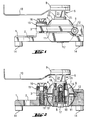
Das in den Fig. 1 bis 3 dargestellte Befestigungselement dient der Festlegung von nicht dargestellten Führungsschienen an der Oberfläche eines Untergrundes, der mit ebenfalls nicht dargestellten Werkzeugen bearbeitet wird, die entlang der Führungsschiene verschiebbar sind. The fastener shown in Figs. 1 to 3 is not used to determine shown guide rails on the surface of a substrate, which also with Tools not shown is edited, which can be moved along the guide rail are.
Das Befestigungselement weist ein Grundelement 1 auf, das zur besseren Auflage auf
der Oberfläche eines nicht dargestellten Bauteiles mit Auflageelementen versehen ist, die
Auflageflächen 14 aufweisen. An dem Grundelement 1 sind beispielsweise 4 Auflageelemente
angeordnet, von denen allerdings nur zwei sichtbar sind. Das Grundelement 1
kann beispielsweise auch nur mit drei Auflageelemente ausgestattet sein, sodass eine
sogenannte "Dreipunkt-Auflage" erreicht werden kann. Der Festlegung des Grundelementes
1 an der Oberfläche des zu bearbeitenden Untergrundes dient eine nicht
dargestellte Befestigungsschraube, die ein Langloch 2 in dem Grundelement 1 durchsetzt
und in eine ebenfalls nicht dargestellte vorbereitete Aufnahmebohrung im Untergrund eindrehbar
ist.The fastening element has a
Auf einer den Auflageflächen 14 gegenüberliegenden Seite weist das Grundelement 1
eine im wesentlichen halbkugelförmig ausgebildete Aufnahmeöffnung 6 auf, die sich in
Richtung der Auflageflächen 14 verjüngt und in der eine Kugel 4 angeordnet ist. Ein mit
der Kugel 4 zusammenwirkendes, mit dem Grundelement 1 in Verbindung stehendes
Klemmelement 3 dient der Festklemmung der Kugel 4 zwischen dem Grundelement 1
und dem Klemmelement 3. Das Klemmelement 3 weist ebenfalls wie das Grundelement 1
eine halbkreisförmige Aufnahmeöffnung 6 auf, die sich in einer von den Auflageflächen
14 abgewandten Richtung verjüngt. Das Klemmelement 3 und das Grundelement 1 sind
mittels einer Drehachse 12 schwenkbar miteinander verbunden, deren Mittellängsachse
parallel zu den Auflageflächen 14 verläuft. Auf die genaue Lage dieser Drehachse wird in
einem später folgenden Abschnitt näher eingegangen.The
Mit Hilfe einer Schraube 16, die eine Durchgangsbohrung des Klemmelementes 3 durchsetzt
und in eine, ein Gegengewinde aufweisende Aufnahmebohrung des Grundelementes
1 eindrehbar ist, lässt sich das Spiel zwischen den halbkreisförmigen Aufnahmeöffnungen
6 des Grundelementes 1 und des Klemmelementes 3 und der Aussenkontur
der Kugel 4 aufheben, sodass die Kugel 4 zwischen dem Grundelement 1 und
dem Klemmelement 3 festgeklemmt wird.With the help of a
Zwischen einem Kopf der Schraube 16 und einer von den Auflageflächen 14 abgewandten
Oberfläche des Klemmelementes 3 ist beispielsweise ein aus zwei Scheiben
bestehendes Ausgleichselement 15 angeordnet. Mit Hilfe dieses Ausgleichselementes 15
wird eine gute Abstützung des Kopfes der Schraube 16 an dem Klemmelement 3 selbst
dann gewährleistet, wenn das Klemmelement 3 gegenüber einer von den Auflageflächen
14 gebildeten Ebene geneigt angeordnet ist. Between a head of the
Die Kugel 4 weist ein Gegenlager 8 in Form einer zylindrischen Durchgangsbohrung auf,
die sich in Richtung der Auflageflächen 14 stufenförmig erweitert. Von zwei einander
gegenüberliegenden Seiten ragt jeweils eine, mit einem flanschartigen Bund versehene
Lagerbuchse 18, 19 in jenen Teil der Durchgangsbohrung, der den kleineren Durchmesser
aufweist. Zwischen den voneinander beabstandeten Lagerbuchsen weist die
Durchgangsbohrung eine zustätzliche radiale Erweiterung in Form einer Hinterschneidung
13 auf. Die Lagerbuchsen 18, 19 dienen der Lagerung eines Verbindungselementes
5, das mit einer Lagerstelle 7 beide Lagerbuchsen 18, 19 durchsetzt, wobei
das freie Ende der Lagerstelle 7 und der stufenförmige Übergang der Durchgangsbohrung
8 in der gleichen Ebene liegen.The ball 4 has a counter bearing 8 in the form of a cylindrical through hole,
which widens step-wise in the direction of the
Vom freien Ende der Lagerstelle 7 aus erstreckt sich eine Gewindebohrung in das Verbindungselement
5, in die eine Schraube 17 eingedreht ist, deren Kopf sich unter
Zwischenlage einer Beilagscheibe an einer, von dem stufenförmigen Übergang der
Durchgangsbohrung gebildeten, den Auflageflächen 14 zugewandten, kreisringförmigen
Anschlagfläche abstützt. Der Aussendurchmesser der Lagerstelle 7 entspricht dem
Innendurchmesser der Lagebuchsen 18, 19 und der Aussendurchmesser der Lagerbuchsen
18, 19 entspricht dem kleineren Durchmesser der die Kugel 4 zentral durchsetzenden
Durchgangsbohrung.A threaded hole extends from the free end of the bearing point 7 into the connecting
An einem, der Lagerstelle 7 gegenüberliegenden freien Endbereich des Verbindungselementes 5 befindet sich ein Exzenter 9, dessen exzentrische Querschnittsfläche in einer senkrecht zur Mittellängsachse der Lagerstelle 7 verlaufenden Ebene liegt. Der Exzenter 9 weist zwei voneinander beabstandete parallel zueinander und parallel zur Mittellängsachse der Lagerstelle 7 verlaufende, gerade Seitenflächen auf.At a free end area of the connecting element opposite the bearing point 7 5 is an eccentric 9, the eccentric cross-sectional area in one is perpendicular to the central longitudinal axis of the bearing 7 plane. The eccentric 9 has two spaced apart parallel to each other and parallel to Center lateral axis of the bearing point 7 extending, straight side surfaces.
In Richtung Auflageflächen 14 schliesst sich direkt an den Exzenter 9 ein Schwenkhebel
10 an, dessen freies Ende in einer von den Auflageflächen 14 abgewandten Richtung
rechtwinklig abgebogen ist. Dieses abgebogene freie Ende des Schwenkhebels 10 ist
beispielsweise mit einer nicht näher dargestellten Verriegelungskontur versehen, mit
deren Hilfe der Exzenter 9 in einer nicht dargestellten Führungsschiene in der
geklemmten Stellung verriegelbar ist, indem die Verriegelungskontur formschlüssig mit
der Führungsschiene zusammenwirkt.In the direction of the
Direkt an den Schwenkhebel 10 schliesst sich eine Schlüsselweite 21 an, über die das
gesamte Verbindungselement 5 mit einem geeigneten, nicht dargestellten Gabelschüssel
verdrehbar ist. A
Die Kugel 4 weist in einer Ebene, die senkrecht zur Mittellängsachse des Gegenlagers 8 verläuft und in der die Kugel 4 die grösste Querschnittsfläche aufweist, eine umlaufend ausgebildete Vertiefung 11 an der Aussenkontur auf.The ball 4 points in a plane that is perpendicular to the central longitudinal axis of the counter bearing 8 runs and in which the ball 4 has the largest cross-sectional area, one circumferential trained recess 11 on the outer contour.
Eine das Grundelement 1 und das Klemmelement 3 schwenkbar miteinander verbindende
Drehachse 12 erstreckt sich im wesentlichen tangential zu der Vertiefung 11 an
der Kugel 4 und parallel zu den Auflageflächen 14 durch das Grundelement 1 sowie das
Klemmelement 3 und ragt seitlich in die Vertiefung 11 der Kugel 4. Durch das
Zusammenwirken der Drehachse 12 mit der Vertiefung 11 in der Kugel 4, wird
gewährleistet, dass das Gegenlager 8 immer in einer senkrechten Position gegenüber
einer von den Auflageflächen 14 gebildeten Ebene verbleibt, selbst dann, wenn das
Verbindungselement 5 gegenüber der Kugel 4 verdreht wird.A pivotally connecting the
Jener Bereich der Drehachse 12, der in die Vertiefung 11 ragt, ist mit einer einseitigen
Ausnehmung 20 versehen. Durch ein Drehen der Drehachse 12 ist die Ausnehmung 20
zur Vertiefung 11 hin ausrichtbar, sodass die Drehachse 12 nicht mehr in diese Vertiefung
11 ragt. Auf diese Weise kann nun die Kugel 4 in eine Position verschwenkt
werden, in der die Mittellängsachse des Gegenlagers 8 nicht mehr senkrecht zu einer von
den Auflageflächen 14 gebildeten Ebene verläuft.That area of the axis of
Claims (7)
Priority Applications (1)
| Application Number | Priority Date | Filing Date | Title |
|---|---|---|---|
| DK00810357T DK1055831T3 (en) | 1999-05-07 | 2000-04-26 | Shine foot for diamond cutting system |
Applications Claiming Priority (2)
| Application Number | Priority Date | Filing Date | Title |
|---|---|---|---|
| DE19921148 | 1999-05-07 | ||
| DE19921148A DE19921148A1 (en) | 1999-05-07 | 1999-05-07 | Slide mount for diamond cutting system with link element turning with respect to locking ball allowing guide rail to swivel in a plane |
Publications (2)
| Publication Number | Publication Date |
|---|---|
| EP1055831A1 true EP1055831A1 (en) | 2000-11-29 |
| EP1055831B1 EP1055831B1 (en) | 2004-11-24 |
Family
ID=7907340
Family Applications (1)
| Application Number | Title | Priority Date | Filing Date |
|---|---|---|---|
| EP00810357A Expired - Lifetime EP1055831B1 (en) | 1999-05-07 | 2000-04-26 | Rail foot for a diamond cutting system |
Country Status (8)
| Country | Link |
|---|---|
| US (1) | US6361238B1 (en) |
| EP (1) | EP1055831B1 (en) |
| JP (1) | JP4531928B2 (en) |
| AT (1) | ATE283432T1 (en) |
| DE (2) | DE19921148A1 (en) |
| DK (1) | DK1055831T3 (en) |
| ES (1) | ES2231143T3 (en) |
| PL (1) | PL195730B1 (en) |
Families Citing this family (19)
| Publication number | Priority date | Publication date | Assignee | Title |
|---|---|---|---|---|
| US6746173B2 (en) * | 2001-04-25 | 2004-06-08 | Japan Servo Co., Ltd. | Universal joint |
| GB0117098D0 (en) * | 2001-07-13 | 2001-09-05 | Renishaw Plc | Pivot joint |
| US7241070B2 (en) * | 2001-07-13 | 2007-07-10 | Renishaw Plc | Pivot joint |
| DE20205827U1 (en) * | 2002-04-15 | 2003-08-28 | Kreul Stephan | Universal ball and socket holder for wall fittings, e.g. lights, includes ball with screwed sections clamping it between them |
| US20050244214A1 (en) * | 2002-07-08 | 2005-11-03 | Kilburn Kip K | Vehicle suspension system |
| US20040066015A1 (en) * | 2002-07-08 | 2004-04-08 | Kip Kilburn | Vehicle suspension system |
| US6918722B1 (en) | 2004-02-27 | 2005-07-19 | Valeda Company Llc | Double plunger track fitting |
| US7637705B2 (en) * | 2004-02-27 | 2009-12-29 | Valeda Company | Track fitting with visual indicia of engagement |
| US7229238B2 (en) * | 2004-03-25 | 2007-06-12 | Valeda Company Llc | Wheelchair docking system |
| ITPD20050143A1 (en) * | 2005-05-18 | 2006-11-19 | Lino Manfrotto & Co Spa | SUPPORT FOR PHOTOGRAPHIC VIDEO EQUIPMENT |
| US7665939B1 (en) | 2006-08-10 | 2010-02-23 | Sure—Lok, Inc. | Retractor anchor with top release |
| US20110097177A1 (en) * | 2009-10-28 | 2011-04-28 | Carnevali Jeffrey D | Ball mount having center fastener |
| CN103047517A (en) * | 2012-12-27 | 2013-04-17 | 中山日高精密工业有限公司 | Novel holder structure |
| FR3001714B1 (en) * | 2013-02-05 | 2016-08-26 | Astrium Sas | DEVICE FOR SUPPORTING AND MAINTAINING CRYOGENIC RESERVOIRS |
| FR3001713B1 (en) * | 2013-02-05 | 2016-07-15 | Astrium Sas | DEVICE FOR RETAINING A TANK IN AN AIRCRAFT |
| US20150314386A1 (en) * | 2014-05-05 | 2015-11-05 | GM Global Technology Operations LLC | Adaptor for a tool or handle |
| ITUA20162560A1 (en) * | 2016-04-13 | 2017-10-13 | Vitec Imaging Solutions S P A | Adjustable module for video-photographic equipment |
| USD847036S1 (en) | 2017-02-02 | 2019-04-30 | Aircraft Gear Corporation | Tie rod end |
| USD847696S1 (en) | 2017-02-02 | 2019-05-07 | Aircraft Gear Corporation | Tie rod connector |
Citations (6)
| Publication number | Priority date | Publication date | Assignee | Title |
|---|---|---|---|---|
| DE2112431A1 (en) * | 1970-03-17 | 1971-10-07 | Eliny Plast Ab | joint |
| FR2548746A1 (en) * | 1983-07-04 | 1985-01-11 | Thomson Brandt | Ball joint which can be immobilised with the aid of just one locking element |
| US4515336A (en) * | 1983-04-14 | 1985-05-07 | Opcon, Inc. | Ball and socket mount for optical sensing system source and/or detector devices |
| US4796508A (en) * | 1986-07-31 | 1989-01-10 | Hoshino Gakki Co., Ltd. | Musical instrument support fixture |
| WO1990014031A1 (en) * | 1989-05-19 | 1990-11-29 | Tridec Iii Corporation | Swivel chair with tiltable seat and a mechanism therefor |
| DE9301268U1 (en) * | 1993-01-30 | 1993-03-11 | Fa. Carl Zeiss, 7920 Heidenheim, De |
Family Cites Families (7)
| Publication number | Priority date | Publication date | Assignee | Title |
|---|---|---|---|---|
| US2664029A (en) * | 1951-04-07 | 1953-12-29 | Richard L Higgins | Remotely adjustable rearview mirror |
| US4026657A (en) * | 1974-09-05 | 1977-05-31 | Textron, Inc. | Sintered spherical articles |
| DE3225052A1 (en) * | 1982-07-05 | 1984-01-05 | Hilti AG, 9494 Schaan | RESISTANT WITH THE APPLICATION OF A TORQUE SERVICING ORGANIZER FOR THREADED BOLTS |
| DE3344064A1 (en) * | 1983-12-06 | 1985-07-04 | Hilti Ag, Schaan | Holding device for drilling tools |
| DE3719164A1 (en) * | 1987-06-09 | 1988-12-29 | Hilti Ag | SPREADING DOWEL WITH LIMITED SPREAD |
| DE4333913C2 (en) * | 1992-10-09 | 1997-11-20 | Link Johs Sonor Gmbh | Adjustment device on length and / or incline adjustable holders, in particular for percussion musical instruments |
| US5899167A (en) * | 1997-08-11 | 1999-05-04 | Furman; Shulim | Display support device for displaying replaceable indicia |
-
1999
- 1999-05-07 DE DE19921148A patent/DE19921148A1/en not_active Withdrawn
-
2000
- 2000-03-23 US US09/533,475 patent/US6361238B1/en not_active Expired - Lifetime
- 2000-04-26 ES ES00810357T patent/ES2231143T3/en not_active Expired - Lifetime
- 2000-04-26 DE DE50008721T patent/DE50008721D1/en not_active Expired - Lifetime
- 2000-04-26 DK DK00810357T patent/DK1055831T3/en active
- 2000-04-26 EP EP00810357A patent/EP1055831B1/en not_active Expired - Lifetime
- 2000-04-26 AT AT00810357T patent/ATE283432T1/en active
- 2000-05-05 PL PL340001A patent/PL195730B1/en unknown
- 2000-05-08 JP JP2000134795A patent/JP4531928B2/en not_active Expired - Fee Related
Patent Citations (6)
| Publication number | Priority date | Publication date | Assignee | Title |
|---|---|---|---|---|
| DE2112431A1 (en) * | 1970-03-17 | 1971-10-07 | Eliny Plast Ab | joint |
| US4515336A (en) * | 1983-04-14 | 1985-05-07 | Opcon, Inc. | Ball and socket mount for optical sensing system source and/or detector devices |
| FR2548746A1 (en) * | 1983-07-04 | 1985-01-11 | Thomson Brandt | Ball joint which can be immobilised with the aid of just one locking element |
| US4796508A (en) * | 1986-07-31 | 1989-01-10 | Hoshino Gakki Co., Ltd. | Musical instrument support fixture |
| WO1990014031A1 (en) * | 1989-05-19 | 1990-11-29 | Tridec Iii Corporation | Swivel chair with tiltable seat and a mechanism therefor |
| DE9301268U1 (en) * | 1993-01-30 | 1993-03-11 | Fa. Carl Zeiss, 7920 Heidenheim, De |
Also Published As
| Publication number | Publication date |
|---|---|
| EP1055831B1 (en) | 2004-11-24 |
| PL195730B1 (en) | 2007-10-31 |
| JP4531928B2 (en) | 2010-08-25 |
| PL340001A1 (en) | 2000-11-20 |
| DE19921148A1 (en) | 2000-11-09 |
| DE50008721D1 (en) | 2004-12-30 |
| ES2231143T3 (en) | 2005-05-16 |
| DK1055831T3 (en) | 2005-04-04 |
| JP2000334730A (en) | 2000-12-05 |
| US6361238B1 (en) | 2002-03-26 |
| ATE283432T1 (en) | 2004-12-15 |
Similar Documents
| Publication | Publication Date | Title |
|---|---|---|
| EP1055831B1 (en) | Rail foot for a diamond cutting system | |
| EP0563542B1 (en) | Device for detachable connection of parts | |
| CH680839A5 (en) | ||
| EP1726403A2 (en) | Lever with height adjustable stop | |
| EP2070440A1 (en) | Table, in particular standing or bistro table | |
| EP3271538A1 (en) | Door hinge or window hinge | |
| EP2097199B1 (en) | System pendulum apparatus and method | |
| AT401080B (en) | BRACKET FOR TORQUE-FREE STORAGE OF GLASS PANELS | |
| AT393797B (en) | BINDING FOR SNOWBOARDS | |
| DE60219018T2 (en) | jOINT COMPOUND | |
| DE2721107A1 (en) | DEVICE FOR CONNECTING A WORK TOOL TO A SUPPORT ARM, IN PARTICULAR TO A HANDLE | |
| DE19821924C2 (en) | Secateurs with a cutting blade and an anvil interacting with it | |
| EP0157890A1 (en) | Cutting tool with cutting head and coupling shaft | |
| CH690451A5 (en) | Hinge. | |
| DE10223448A1 (en) | Ground anchor insertion tool has transverse torque bar engaging with vertical shank to socket with locking pin in earth anchor | |
| DE4240361C2 (en) | Three-dimensionally adjustable motor vehicle door hinge | |
| DE1958554C3 (en) | Cutting tool for machining | |
| DE3102800C2 (en) | Clamping device for clamping workpieces on the table or the like. a machine tool | |
| DE202005012422U1 (en) | Handrails connecting unit, has swivel plate and threaded part to provide connection of handrails with arbitrary rotation of hemispheres against each other, and threaded pin to enable change in hemispheres` rotation angle | |
| EP1598213B1 (en) | Lockable fast adjustable compass | |
| DE202004000843U1 (en) | Wrench has slide-fit handle terminating in U-shaped frame for swing-mounted drum ratchet head | |
| EP1070802A2 (en) | Railing system | |
| EP2562460B1 (en) | Dispositif de réglage | |
| EP1245200A2 (en) | Bite-fork holder with central clamp | |
| DE1559797C (en) | Bearing for window sashes that can be swiveled one after the other about two parallel axes by about 180 degrees |
Legal Events
| Date | Code | Title | Description |
|---|---|---|---|
| PUAI | Public reference made under article 153(3) epc to a published international application that has entered the european phase |
Free format text: ORIGINAL CODE: 0009012 |
|
| AK | Designated contracting states |
Kind code of ref document: A1 Designated state(s): AT BE CH CY DE DK ES FI FR GB GR IE IT LI LU MC NL PT SE |
|
| AX | Request for extension of the european patent |
Free format text: AL;LT;LV;MK;RO;SI |
|
| 17P | Request for examination filed |
Effective date: 20010529 |
|
| AKX | Designation fees paid |
Free format text: AT BE CH CY DE DK ES FI FR GB GR IE IT LI LU MC NL PT SE |
|
| GRAP | Despatch of communication of intention to grant a patent |
Free format text: ORIGINAL CODE: EPIDOSNIGR1 |
|
| RIC1 | Information provided on ipc code assigned before grant |
Ipc: 7F 16M 11/14 B Ipc: 7F 16C 11/10 A |
|
| GRAS | Grant fee paid |
Free format text: ORIGINAL CODE: EPIDOSNIGR3 |
|
| GRAA | (expected) grant |
Free format text: ORIGINAL CODE: 0009210 |
|
| AK | Designated contracting states |
Kind code of ref document: B1 Designated state(s): AT BE CH CY DE DK ES FI FR GB GR IE IT LI LU MC NL PT SE |
|
| PG25 | Lapsed in a contracting state [announced via postgrant information from national office to epo] |
Ref country code: IE Free format text: LAPSE BECAUSE OF FAILURE TO SUBMIT A TRANSLATION OF THE DESCRIPTION OR TO PAY THE FEE WITHIN THE PRESCRIBED TIME-LIMIT Effective date: 20041124 Ref country code: FI Free format text: LAPSE BECAUSE OF FAILURE TO SUBMIT A TRANSLATION OF THE DESCRIPTION OR TO PAY THE FEE WITHIN THE PRESCRIBED TIME-LIMIT Effective date: 20041124 |
|
| REG | Reference to a national code |
Ref country code: GB Ref legal event code: FG4D Free format text: NOT ENGLISH |
|
| REG | Reference to a national code |
Ref country code: SE Ref legal event code: TRGR Ref country code: CH Ref legal event code: EP |
|
| REF | Corresponds to: |
Ref document number: 50008721 Country of ref document: DE Date of ref document: 20041230 Kind code of ref document: P |
|
| REG | Reference to a national code |
Ref country code: IE Ref legal event code: FG4D Free format text: GERMAN |
|
| GBT | Gb: translation of ep patent filed (gb section 77(6)(a)/1977) |
Effective date: 20050202 |
|
| PG25 | Lapsed in a contracting state [announced via postgrant information from national office to epo] |
Ref country code: GR Free format text: LAPSE BECAUSE OF FAILURE TO SUBMIT A TRANSLATION OF THE DESCRIPTION OR TO PAY THE FEE WITHIN THE PRESCRIBED TIME-LIMIT Effective date: 20050224 |
|
| REG | Reference to a national code |
Ref country code: DK Ref legal event code: T3 |
|
| PGFP | Annual fee paid to national office [announced via postgrant information from national office to epo] |
Ref country code: IE Payment date: 20050414 Year of fee payment: 6 |
|
| PG25 | Lapsed in a contracting state [announced via postgrant information from national office to epo] |
Ref country code: CY Free format text: LAPSE BECAUSE OF FAILURE TO SUBMIT A TRANSLATION OF THE DESCRIPTION OR TO PAY THE FEE WITHIN THE PRESCRIBED TIME-LIMIT Effective date: 20050426 Ref country code: LU Free format text: LAPSE BECAUSE OF NON-PAYMENT OF DUE FEES Effective date: 20050426 |
|
| PG25 | Lapsed in a contracting state [announced via postgrant information from national office to epo] |
Ref country code: MC Free format text: LAPSE BECAUSE OF NON-PAYMENT OF DUE FEES Effective date: 20050430 |
|
| REG | Reference to a national code |
Ref country code: ES Ref legal event code: FG2A Ref document number: 2231143 Country of ref document: ES Kind code of ref document: T3 |
|
| REG | Reference to a national code |
Ref country code: IE Ref legal event code: FD4D |
|
| PLBE | No opposition filed within time limit |
Free format text: ORIGINAL CODE: 0009261 |
|
| STAA | Information on the status of an ep patent application or granted ep patent |
Free format text: STATUS: NO OPPOSITION FILED WITHIN TIME LIMIT |
|
| ET | Fr: translation filed | ||
| 26N | No opposition filed |
Effective date: 20050825 |
|
| PG25 | Lapsed in a contracting state [announced via postgrant information from national office to epo] |
Ref country code: PT Free format text: LAPSE BECAUSE OF NON-PAYMENT OF DUE FEES Effective date: 20050424 |
|
| REG | Reference to a national code |
Ref country code: FR Ref legal event code: PLFP Year of fee payment: 17 |
|
| REG | Reference to a national code |
Ref country code: FR Ref legal event code: PLFP Year of fee payment: 18 |
|
| REG | Reference to a national code |
Ref country code: FR Ref legal event code: PLFP Year of fee payment: 19 |
|
| PGFP | Annual fee paid to national office [announced via postgrant information from national office to epo] |
Ref country code: NL Payment date: 20180418 Year of fee payment: 19 |
|
| PGFP | Annual fee paid to national office [announced via postgrant information from national office to epo] |
Ref country code: ES Payment date: 20180525 Year of fee payment: 19 Ref country code: CH Payment date: 20180419 Year of fee payment: 19 Ref country code: DE Payment date: 20180420 Year of fee payment: 19 Ref country code: DK Payment date: 20180418 Year of fee payment: 19 |
|
| PGFP | Annual fee paid to national office [announced via postgrant information from national office to epo] |
Ref country code: MC Payment date: 20170828 Year of fee payment: 10 Ref country code: FR Payment date: 20180420 Year of fee payment: 19 Ref country code: BE Payment date: 20180418 Year of fee payment: 19 |
|
| PGFP | Annual fee paid to national office [announced via postgrant information from national office to epo] |
Ref country code: SE Payment date: 20180418 Year of fee payment: 19 |
|
| PGFP | Annual fee paid to national office [announced via postgrant information from national office to epo] |
Ref country code: GB Payment date: 20180418 Year of fee payment: 19 |
|
| PGFP | Annual fee paid to national office [announced via postgrant information from national office to epo] |
Ref country code: IT Payment date: 20190429 Year of fee payment: 20 |
|
| REG | Reference to a national code |
Ref country code: DE Ref legal event code: R119 Ref document number: 50008721 Country of ref document: DE |
|
| REG | Reference to a national code |
Ref country code: CH Ref legal event code: PL |
|
| REG | Reference to a national code |
Ref country code: DK Ref legal event code: EBP Effective date: 20190430 |
|
| REG | Reference to a national code |
Ref country code: SE Ref legal event code: EUG |
|
| REG | Reference to a national code |
Ref country code: NL Ref legal event code: MM Effective date: 20190501 |
|
| REG | Reference to a national code |
Ref country code: AT Ref legal event code: MM01 Ref document number: 283432 Country of ref document: AT Kind code of ref document: T Effective date: 20190426 |
|
| REG | Reference to a national code |
Ref country code: BE Ref legal event code: MM Effective date: 20190430 |
|
| GBPC | Gb: european patent ceased through non-payment of renewal fee |
Effective date: 20190426 |
|
| PG25 | Lapsed in a contracting state [announced via postgrant information from national office to epo] |
Ref country code: NL Free format text: LAPSE BECAUSE OF NON-PAYMENT OF DUE FEES Effective date: 20190501 Ref country code: DE Free format text: LAPSE BECAUSE OF NON-PAYMENT OF DUE FEES Effective date: 20191101 Ref country code: GB Free format text: LAPSE BECAUSE OF NON-PAYMENT OF DUE FEES Effective date: 20190426 Ref country code: AT Free format text: LAPSE BECAUSE OF NON-PAYMENT OF DUE FEES Effective date: 20190426 Ref country code: LI Free format text: LAPSE BECAUSE OF NON-PAYMENT OF DUE FEES Effective date: 20190430 Ref country code: CH Free format text: LAPSE BECAUSE OF NON-PAYMENT OF DUE FEES Effective date: 20190430 Ref country code: SE Free format text: LAPSE BECAUSE OF NON-PAYMENT OF DUE FEES Effective date: 20190427 |
|
| PG25 | Lapsed in a contracting state [announced via postgrant information from national office to epo] |
Ref country code: BE Free format text: LAPSE BECAUSE OF NON-PAYMENT OF DUE FEES Effective date: 20190430 |
|
| PG25 | Lapsed in a contracting state [announced via postgrant information from national office to epo] |
Ref country code: DK Free format text: LAPSE BECAUSE OF NON-PAYMENT OF DUE FEES Effective date: 20190430 |
|
| PG25 | Lapsed in a contracting state [announced via postgrant information from national office to epo] |
Ref country code: FR Free format text: LAPSE BECAUSE OF NON-PAYMENT OF DUE FEES Effective date: 20190430 |
|
| REG | Reference to a national code |
Ref country code: ES Ref legal event code: FD2A Effective date: 20200901 |
|
| PG25 | Lapsed in a contracting state [announced via postgrant information from national office to epo] |
Ref country code: ES Free format text: LAPSE BECAUSE OF NON-PAYMENT OF DUE FEES Effective date: 20190427 |