EP1055738A2 - Method of manufacturing laminated ring and heat treatment apparatus for use in such method - Google Patents
Method of manufacturing laminated ring and heat treatment apparatus for use in such method Download PDFInfo
- Publication number
- EP1055738A2 EP1055738A2 EP00304504A EP00304504A EP1055738A2 EP 1055738 A2 EP1055738 A2 EP 1055738A2 EP 00304504 A EP00304504 A EP 00304504A EP 00304504 A EP00304504 A EP 00304504A EP 1055738 A2 EP1055738 A2 EP 1055738A2
- Authority
- EP
- European Patent Office
- Prior art keywords
- rings
- nitriding
- chamber
- aging
- temperature
- Prior art date
- Legal status (The legal status is an assumption and is not a legal conclusion. Google has not performed a legal analysis and makes no representation as to the accuracy of the status listed.)
- Granted
Links
- 238000010438 heat treatment Methods 0.000 title claims abstract description 51
- 238000000034 method Methods 0.000 title claims description 88
- 238000004519 manufacturing process Methods 0.000 title claims description 16
- 238000005121 nitriding Methods 0.000 claims abstract description 181
- 230000032683 aging Effects 0.000 claims abstract description 179
- 239000012298 atmosphere Substances 0.000 claims abstract description 35
- QGZKDVFQNNGYKY-UHFFFAOYSA-N Ammonia Chemical compound N QGZKDVFQNNGYKY-UHFFFAOYSA-N 0.000 claims abstract description 33
- 238000001816 cooling Methods 0.000 claims abstract description 18
- 229910001240 Maraging steel Inorganic materials 0.000 claims abstract description 16
- 230000005540 biological transmission Effects 0.000 claims abstract description 13
- 150000004767 nitrides Chemical class 0.000 claims description 26
- 239000007789 gas Substances 0.000 claims description 21
- 229910021529 ammonia Inorganic materials 0.000 claims description 9
- 238000005096 rolling process Methods 0.000 claims description 7
- 239000002184 metal Substances 0.000 claims description 5
- 229910052751 metal Inorganic materials 0.000 claims description 5
- 230000002431 foraging effect Effects 0.000 claims 1
- IJGRMHOSHXDMSA-UHFFFAOYSA-N Atomic nitrogen Chemical compound N#N IJGRMHOSHXDMSA-UHFFFAOYSA-N 0.000 description 14
- 229910052757 nitrogen Inorganic materials 0.000 description 7
- 230000007423 decrease Effects 0.000 description 5
- 230000000694 effects Effects 0.000 description 4
- 238000005452 bending Methods 0.000 description 3
- 229910000797 Ultra-high-strength steel Inorganic materials 0.000 description 2
- 230000000052 comparative effect Effects 0.000 description 2
- 239000013078 crystal Substances 0.000 description 2
- 238000009826 distribution Methods 0.000 description 2
- 239000000463 material Substances 0.000 description 2
- 229910001209 Low-carbon steel Inorganic materials 0.000 description 1
- 238000003483 aging Methods 0.000 description 1
- 239000001257 hydrogen Substances 0.000 description 1
- 229910052739 hydrogen Inorganic materials 0.000 description 1
- 125000004435 hydrogen atom Chemical class [H]* 0.000 description 1
- 229910000765 intermetallic Inorganic materials 0.000 description 1
- 229910000734 martensite Inorganic materials 0.000 description 1
- 239000012299 nitrogen atmosphere Substances 0.000 description 1
- QJGQUHMNIGDVPM-UHFFFAOYSA-N nitrogen group Chemical group [N] QJGQUHMNIGDVPM-UHFFFAOYSA-N 0.000 description 1
- 230000003252 repetitive effect Effects 0.000 description 1
- 238000003466 welding Methods 0.000 description 1
Images





Classifications
-
- B—PERFORMING OPERATIONS; TRANSPORTING
- B23—MACHINE TOOLS; METAL-WORKING NOT OTHERWISE PROVIDED FOR
- B23P—METAL-WORKING NOT OTHERWISE PROVIDED FOR; COMBINED OPERATIONS; UNIVERSAL MACHINE TOOLS
- B23P15/00—Making specific metal objects by operations not covered by a single other subclass or a group in this subclass
-
- C—CHEMISTRY; METALLURGY
- C21—METALLURGY OF IRON
- C21D—MODIFYING THE PHYSICAL STRUCTURE OF FERROUS METALS; GENERAL DEVICES FOR HEAT TREATMENT OF FERROUS OR NON-FERROUS METALS OR ALLOYS; MAKING METAL MALLEABLE, e.g. BY DECARBURISATION OR TEMPERING
- C21D9/00—Heat treatment, e.g. annealing, hardening, quenching or tempering, adapted for particular articles; Furnaces therefor
- C21D9/40—Heat treatment, e.g. annealing, hardening, quenching or tempering, adapted for particular articles; Furnaces therefor for rings; for bearing races
-
- C—CHEMISTRY; METALLURGY
- C23—COATING METALLIC MATERIAL; COATING MATERIAL WITH METALLIC MATERIAL; CHEMICAL SURFACE TREATMENT; DIFFUSION TREATMENT OF METALLIC MATERIAL; COATING BY VACUUM EVAPORATION, BY SPUTTERING, BY ION IMPLANTATION OR BY CHEMICAL VAPOUR DEPOSITION, IN GENERAL; INHIBITING CORROSION OF METALLIC MATERIAL OR INCRUSTATION IN GENERAL
- C23C—COATING METALLIC MATERIAL; COATING MATERIAL WITH METALLIC MATERIAL; SURFACE TREATMENT OF METALLIC MATERIAL BY DIFFUSION INTO THE SURFACE, BY CHEMICAL CONVERSION OR SUBSTITUTION; COATING BY VACUUM EVAPORATION, BY SPUTTERING, BY ION IMPLANTATION OR BY CHEMICAL VAPOUR DEPOSITION, IN GENERAL
- C23C8/00—Solid state diffusion of only non-metal elements into metallic material surfaces; Chemical surface treatment of metallic material by reaction of the surface with a reactive gas, leaving reaction products of surface material in the coating, e.g. conversion coatings, passivation of metals
- C23C8/06—Solid state diffusion of only non-metal elements into metallic material surfaces; Chemical surface treatment of metallic material by reaction of the surface with a reactive gas, leaving reaction products of surface material in the coating, e.g. conversion coatings, passivation of metals using gases
- C23C8/08—Solid state diffusion of only non-metal elements into metallic material surfaces; Chemical surface treatment of metallic material by reaction of the surface with a reactive gas, leaving reaction products of surface material in the coating, e.g. conversion coatings, passivation of metals using gases only one element being applied
- C23C8/24—Nitriding
- C23C8/26—Nitriding of ferrous surfaces
-
- C—CHEMISTRY; METALLURGY
- C23—COATING METALLIC MATERIAL; COATING MATERIAL WITH METALLIC MATERIAL; CHEMICAL SURFACE TREATMENT; DIFFUSION TREATMENT OF METALLIC MATERIAL; COATING BY VACUUM EVAPORATION, BY SPUTTERING, BY ION IMPLANTATION OR BY CHEMICAL VAPOUR DEPOSITION, IN GENERAL; INHIBITING CORROSION OF METALLIC MATERIAL OR INCRUSTATION IN GENERAL
- C23C—COATING METALLIC MATERIAL; COATING MATERIAL WITH METALLIC MATERIAL; SURFACE TREATMENT OF METALLIC MATERIAL BY DIFFUSION INTO THE SURFACE, BY CHEMICAL CONVERSION OR SUBSTITUTION; COATING BY VACUUM EVAPORATION, BY SPUTTERING, BY ION IMPLANTATION OR BY CHEMICAL VAPOUR DEPOSITION, IN GENERAL
- C23C8/00—Solid state diffusion of only non-metal elements into metallic material surfaces; Chemical surface treatment of metallic material by reaction of the surface with a reactive gas, leaving reaction products of surface material in the coating, e.g. conversion coatings, passivation of metals
- C23C8/40—Solid state diffusion of only non-metal elements into metallic material surfaces; Chemical surface treatment of metallic material by reaction of the surface with a reactive gas, leaving reaction products of surface material in the coating, e.g. conversion coatings, passivation of metals using liquids, e.g. salt baths, liquid suspensions
- C23C8/42—Solid state diffusion of only non-metal elements into metallic material surfaces; Chemical surface treatment of metallic material by reaction of the surface with a reactive gas, leaving reaction products of surface material in the coating, e.g. conversion coatings, passivation of metals using liquids, e.g. salt baths, liquid suspensions only one element being applied
- C23C8/48—Nitriding
- C23C8/50—Nitriding of ferrous surfaces
-
- F—MECHANICAL ENGINEERING; LIGHTING; HEATING; WEAPONS; BLASTING
- F16—ENGINEERING ELEMENTS AND UNITS; GENERAL MEASURES FOR PRODUCING AND MAINTAINING EFFECTIVE FUNCTIONING OF MACHINES OR INSTALLATIONS; THERMAL INSULATION IN GENERAL
- F16G—BELTS, CABLES, OR ROPES, PREDOMINANTLY USED FOR DRIVING PURPOSES; CHAINS; FITTINGS PREDOMINANTLY USED THEREFOR
- F16G5/00—V-belts, i.e. belts of tapered cross-section
- F16G5/16—V-belts, i.e. belts of tapered cross-section consisting of several parts
-
- B—PERFORMING OPERATIONS; TRANSPORTING
- B21—MECHANICAL METAL-WORKING WITHOUT ESSENTIALLY REMOVING MATERIAL; PUNCHING METAL
- B21B—ROLLING OF METAL
- B21B5/00—Extending closed shapes of metal bands by rolling
-
- C—CHEMISTRY; METALLURGY
- C21—METALLURGY OF IRON
- C21D—MODIFYING THE PHYSICAL STRUCTURE OF FERROUS METALS; GENERAL DEVICES FOR HEAT TREATMENT OF FERROUS OR NON-FERROUS METALS OR ALLOYS; MAKING METAL MALLEABLE, e.g. BY DECARBURISATION OR TEMPERING
- C21D1/00—General methods or devices for heat treatment, e.g. annealing, hardening, quenching or tempering
- C21D1/26—Methods of annealing
-
- Y—GENERAL TAGGING OF NEW TECHNOLOGICAL DEVELOPMENTS; GENERAL TAGGING OF CROSS-SECTIONAL TECHNOLOGIES SPANNING OVER SEVERAL SECTIONS OF THE IPC; TECHNICAL SUBJECTS COVERED BY FORMER USPC CROSS-REFERENCE ART COLLECTIONS [XRACs] AND DIGESTS
- Y10—TECHNICAL SUBJECTS COVERED BY FORMER USPC
- Y10T—TECHNICAL SUBJECTS COVERED BY FORMER US CLASSIFICATION
- Y10T29/00—Metal working
- Y10T29/49—Method of mechanical manufacture
- Y10T29/49789—Obtaining plural product pieces from unitary workpiece
- Y10T29/49798—Dividing sequentially from leading end, e.g., by cutting or breaking
Definitions
- the present invention relates to a method of manufacturing a laminated ring for use as a belt in transmitting power in a continuously variable transmission, and a heat treatment apparatus for use in such a method.
- Continuously variable transmissions have a power transmitting belt trained around a pair of pulleys.
- the power transmitting belt comprises a laminated ring composed of a plurality of rings and mounted on and held by an element of predetermined shape.
- the laminated ring is straight in shape when traveling between the pulleys, and curved in shape when running along the pulleys.
- the laminated ring undergoes severe bending deformations due to repetitive cycles of the straight and curved states. Therefore, the laminated ring is required to have a mechanical strength large enough to withstand the severe bending deformations.
- the maraging steel is a low-carbon steel containing 17 to 19 % of Ni, and Co, Mo, Ti, etc.
- the maraging steel is heated to a suitable temperature after being subjected to a solution treatment, it causes age hardening in a martensitic state, resulting in an ultra-high strength steel that is highly strong and highly tough.
- the maraging steel is highly suitable for use as the material of the laminated ring.
- the laminated ring has heretofore been manufactured according to the following process:
- the ends of a thin sheet of maraging steel that is an ultra-high strength steel are welded to each other, producing a cylindrical drum.
- the cylindrical drum is subjected to a first solution treatment in order to uniformize the hardness that has been partly increased due to the heat applied when the thin sheet of maraging steel was welded.
- the cylindrical drum is severed into rings of certain width, which are rolled to a predetermined length.
- the rings are then subjected to a second solution treatment in order to recrystallize the rolled structure for restoring the metal crystal grain configuration that has been deformed by the rolling process.
- the rings that has been subjected to the second solution treatment are corrected into predetermined circumferential lengths, and aged and nitrided for increased hardness.
- the rings of slightly different circumferential lengths are fitted together into a laminated ring.
- the rings are aged to cause the maraging steel to develop aged hardness thereby to impart a high strength to the rings.
- the rings are placed in an aging chamber, and the interior of the aging chamber is heated to a predetermined aging temperature, e.g., 480 to 520°C, and thereafter is held at the aging temperature for a predetermined period of time.
- the aging is performed in an inactive gas atmosphere such as nitrogen or the like in order to prevent an oxide layer from being formed on the surface of the rings.
- the rings are aged, an intermetallic compound is separated out in the metal structure of the maraging steel, resulting in aged hardness for high strength and high toughness.
- the rings are then case-hardened because they need to have wear resistance and fatigue-resistant strength for use as the laminated ring.
- the rings are case-hardened by nitriding the rings to form a nitride layer in their surface.
- the rings are nitrided by a gas nitriding process or a gas soft-nitriding process.
- nitrogen produced when ammonia is decomposed penetrates the metal structure of the maraging steel for thereby producing a nitride layer in the surface of the rings to harden the same for increased wear resistance and increased fatigue-resistant strength. If the rings are nitrided, then the rings are repeatedly heated to respective temperatures in the aging chamber and the nitriding chamber, kept at the temperatures for respective periods of time, and then cooled. Consequently, periods of time required for the aging and nitriding processes are increased, resulting in an increase in the manufacturing cost.
- One solution to the above problem would be to successively age and nitride the rings in one processing chamber. Specifically, the rings are placed in the processing chamber, and the interior of the processing chamber is heated to an aging temperature and kept at the aging chamber for a predetermined period of time to age the rings. Thereafter, the interior of the processing chamber is not cooled, but the atmosphere in the processing chamber is replaced with an ammonia gas atmosphere or a mixed atmosphere of ammonia and RX gases, and the interior of the processing chamber is kept at a predetermined nitriding temperature for a predetermined period of time to effect gas nitriding or gas soft-nitriding on the rings.
- the above proposed process is disadvantageous in that the atmosphere changed for the nitriding process after the aging process tends to be not stabilized easily.
- Another solution would be to simultaneously age and nitride the rings in one processing chamber. Specifically, the heating of the rings for the gas nitriding or gas soft-nitriding doubles as the heating of the rings for the aging. However, this process is problematic in that it is difficult to adjust the atmosphere in order to achieve an appropriate aging hardness and a nitride layer of a suitable depth.
- the aging process causes the rings to shrink their volume thereof to reduce their circumferential lengths. It is also known that when the nitriding process is carried out, the volume of the rings is increased to increase their circumferential lengths because nitrogen penetrates the surface of the rings to form the nitride layer therein.
- the rings which have been aged and nitrided suffer errors on the corrected circumferential lengths due to the reduction in the circumferential lengths in the aging process and the increase in the circumferential lengths in the nitriding process.
- the rings are measured for their circumferential lengths after the aging process and the nitriding process, and classified according to the magnitude of errors of the measured circumferential lengths with respect to the corrected circumferential lengths.
- those of the classified rings which have such circumferential lengths that they can be fitted together are chosen and combined into a laminated ring.
- the errors of the circumferential lengths after the aging process and the nitriding process with respect to the corrected circumferential lengths should preferably be kept in the range of ⁇ 80 ⁇ m.
- Another object of the present invention is to provide a method of manufacturing a laminated ring of excellent dimensional stability by allowing easy selection of rings which have been aged and nitrided and whose circumferential lengths are suitable for being fitted together.
- Still another object of the present invention is to provide a heat treatment apparatus that is suitable for use in such a method of manufacturing a laminated ring.
- a method of manufacturing a laminated ring for use as a belt in transmitting power in a continuously variable transmission comprising the steps of severing a cylindrical drum, which comprises a sheet of maraging steel with welded opposite ends, into a plurality of rings of predetermined width, rolling the rings to a predetermined length, correcting circumferential lengths of the rings, aging the rings by placing the rings into an aging chamber, heating the aging chamber to a predetermined aging temperature, and keeping the rings at the predetermined aging temperature for a predetermined period of time, thereafter, nitriding the rings by transferring the rings from the aging chamber into a nitriding chamber which is disposed independently of the aging chamber and has been heated to a predetermined nitriding temperature, while maintaining the rings at the aging temperature, keeping the rings at the nitriding temperature in an atmosphere containing ammonia gas for a predetermined period of time, and cooling the rings, and stacking the rings into a laminated
- the rings which have been aged in the aging chamber are not cooled, but kept at the aging temperature and transferred into the nitriding chamber. Since the nitriding chamber has already been heated to the nitriding temperature, the rings transferred into the nitriding chamber are directly kept at the nitriding temperature for the predetermined period of time and nitrided in the atmosphere containing at least the ammonia gas.
- a process of cooling the rings after they have been aged and also a process of heating the rings to the nitriding temperature to nitride the rings, which have heretofore been employed, are omitted, and the total processing time is reduced. Furthermore, since the nitriding chamber is disposed independently of the aging chamber, it is not necessary to change atmospheres between the aging and nitriding processes, and the rings can be nitrided in the stable atmosphere.
- the step of nitriding the rings may comprise the step of gas-nitriding the rings by keeping the rings at the nitriding temperature in an ammonia gas atmosphere for the predetermined period of time or gas-soft-nitriding the rings by keeping the rings at the nitriding temperature in a mixed atmosphere of ammonia and RX gases for the predetermined period of time.
- the ammonia gas atmosphere may contain other inactive gases than pure ammonia.
- the rings should preferably be nitrided at the nitriding temperature which is equal to or higher than the aging temperature.
- the method may advantageously be carried out using a heat treatment apparatus in which the aging chamber is connected to the nitriding chamber through an openable and closable door.
- the rings are transferred from the aging chamber into the nitriding chamber through the openable and closable door.
- the atmosphere containing ammonia gas in the nitriding chamber i.e., the ammonia gas atmosphere or the mixed atmosphere of ammonia and RX gases can be maintained in a stable state.
- the door is opened to allow the rings to be quickly transferred from the aging chamber into the nitriding chamber.
- the method may further advantageously be carried out using a heat treatment apparatus in which the aging chamber is connected through a first openable and closable door to an intermediate chamber which has been heated to a temperature equal to the aging temperature and the nitriding temperature or a temperature intermediate between the aging temperature and the nitriding temperature, and the intermediate chamber is connected to the nitriding chamber through a second openable and closable door.
- the rings are transferred from the aging chamber into the nitriding chamber successively through the first openable and closable door, the intermediate chamber, and the second openable and closable door.
- the temperature in the intermediate chamber is the same as the temperature in the aging chamber and the nitriding chamber, i.e., a gas-nitriding chamber or a gas-soft-nitriding chamber. If the nitriding temperature is higher than the aging temperature, then the temperature in the intermediate chamber is intermediate between the temperature in the aging chamber and the temperature in the nitriding chamber.
- the rings When the rings are transferred from the aging chamber into the nitriding chamber, the rings are temporarily placed in the intermediate chamber, and the effect of temperature differences on the rings upon the transfer is reduced.
- the intermediate chamber is effective to prevent the atmosphere in the aging chamber from flowing into the nitriding chamber, and hence prevent the atmosphere in the nitriding chamber from being unstabilized.
- the rings after they have been nitrided may be cooled in the nitriding chamber or outside of the nitriding chamber. If the nitrided rings are to be cooled outside of the nitriding chamber, then the nitrided rings may be transferred into a cooling chamber which is connected to the nitriding chamber through an openable and closable door, and cooled in the cooling chamber.
- the independent cooling chamber permits the atmosphere in the nitriding chamber to be stabilized. By quickly transferring the nitrided rings into the cooling chamber, the efficiency with which to transfer the rings is increased for contribution to automating the heat treatment apparatus.
- the openable and closable door disposed between the aging chamber and the nitriding chamber, or between the aging chamber and the intermediate chamber, or between the intermediate chamber and the nitriding chamber, or between the nitriding chamber and the cooling chamber should preferably be vertically movable.
- the door which is vertically movable to be opened and closed is effective to prevent the atmospheres in the aging chamber and the nitriding chamber from becoming unstable.
- the rings When the rings are aged, they produce aged hardness for high mechanical strength. When the rings are nitrided after they have been aged, the aging may be accelerated due to the heating in the nitriding process, tending to reduce the mechanical strength which has been achieved.
- the rings are aged in a range in which aged hardness thereof is less than a maximum value, and the aged hardness of the rings reaches the maximum value when the rings are nitrided.
- the aging in the range in which aged hardness is less than a maximum value is referred to as "sub-aging”
- the aging accelerated after the aged hardness has reached the maximum value thereby to reduce the mechanical strength is referred to as "excessive aging".
- the rings are aged for sub-aging in the aging chamber, and the aged hardness of the rings is caused to reach the maximum value by the heat produced in the subsequent nitriding process, so that the aged hardness will have an appropriate level.
- the rings are preferably aged in a temperature range from 480 to 500°C for less than 60 minutes. If the aging temperature were less than 480°C, then the aged hardness would not reach the maximum value even when heated for 60 minutes, but in the sub-aged region, and a long period of time would be required to achieve the appropriate level of aged hardness. If the aging temperature is 500°C, when the rings are aged for a period of time in excess of 60 minutes, the rings suffer excessive aging, and the aged hardness starts to decrease. If the aging temperature exceeded 500°C, then the rings would suffer excessive aging even when the rings are aged for a period of time less than 60 minutes.
- the rings are preferably nitrided in a temperature range from 480 to 520°C at the nitriding temperature which is the same as or higher than the aging temperature for a period of time ranging from 45 to 60 minutes.
- nitrogen penetrates the surface of each of the rings to form a nitride layer therein to produce hardness.
- Each of the nitrided rings develops such a hardness gradient that the hardness progressively decreases along the depth to which nitrogen goes into the ring from the surface thereof. Since the rings are used in a stacked state, each of the rings is required to have an appropriate hardness gradient from the surface of the ring into the ring for the resistance to fatigue due to relative slippage caused between the surfaces of the rings.
- the nitriding temperature were less than 480°C and the rings were nitrided for less than 45 minutes, then the produced hardness gradient would not reach a required level of hardness. If the nitriding temperature were higher than 520°C and the rings were nitrided for more than 60 minutes, then the produced nitride layer would be deep and the internal hardness would be lowered.
- the rings are aged in a temperature range from 450 to 500°C for a period of time ranging from 2 to 3 hours, and nitrided in a temperature range from 450 to 500°C at the nitriding temperature which is the same as or higher than the aging temperature for a period of time ranging from 30 to 120 minutes, so that the errors of the circumferential lengths of the nitrided rings with respect to the corrected circumferential lengths of the rings fall within a predetermined error range, e.g., an error range of ⁇ 80 ⁇ m.
- a predetermined error range e.g., an error range of ⁇ 80 ⁇ m.
- the rings whose circumferential lengths have been corrected are aged in a temperature range from 450 to 500°C for a period of time ranging from 2 to 3 hours, and nitrided in a temperature range from 450 to 500°C at the nitriding temperature which is the same as or higher than the aging temperature for a period of time ranging from 30 to 120 minutes.
- the shrinkage of the rings in the aging process and the expansion of the rings in the nitriding process are balanced to reduce the errors of the circumferential lengths of the aged and nitrided rings with respect to the corrected circumferential lengths. Therefore, those rings that can be fitted together can easily be selected after the aging and nitriding processes.
- the shrinkage of the rings in the aging process would exceed the expansion of the rings in the nitriding process, increasing the errors of the circumferential lengths of the aged and nitrided rings with respect to the corrected circumferential lengths in a manner to reduce the circumferential lengths.
- the rings are preferably nitrided such that the thickness of a nitride layer in the surface of each of the rings is in a range from 20 to 40 % of the overall thickness of the ring.
- the thickness of the nitride layer in the surface of each of the rings were smaller than 20 % the overall thickness of the ring, then no sufficient hardness would be reached by the nitriding process, and the shrinkage of the rings in the aging process would exceed the expansion of the rings in the nitriding process, increasing the errors of the circumferential lengths of the aged and nitrided rings with respect to the corrected circumferential lengths in a manner to reduce the circumferential lengths.
- the thickness of the nitride layer in the surface of each of the rings were greater than 40 % the overall thickness of the ring, then the expansion of the rings in the nitriding process would exceed the shrinkage of the rings in the aging process, increasing the errors of the circumferential lengths of the aged and nitrided rings with respect to the corrected circumferential lengths in a manner to increase the circumferential lengths.
- a thin sheet 1 of maraging steel is bent into a loop, whose opposite ends are welded to each other to produce a cylindrical drum 2. Since the maraging steel exhibits aged hardness due to the heat applied when the thin sheet 1 of maraging steel was welded, the cylindrical drum 2 has regions of increased hardness on opposite sides of a welded seam 2a thereof. Therefore, the cylindrical drum 2 suffers hardness irregularities.
- the cylindrical drum 2 is placed in a vacuum furnace 3 and kept at a temperature in the range from 820 to 830°C for a period of time ranging from 20 to 60 minutes in a first solution treatment process.
- the first solution treatment process thus carried out uniformizes the hardness of the cylindrical drum 2 and removes welding strains therefrom.
- the cylindrical drum 2 is removed from the vacuum furnace 3, and severed into rings 4 of certain width.
- the rings 4 have their edges burred due to the severing. The burred edges are beveled off by a barrel grinding process. Thereafter, the rings 4 are rolled by a rolling reduction ranging from 40 to 50 %. The rolled rings 4 are placed in a heating furnace 5 in which they are subject to a second solution treatment process. In the second solution treatment process, the rings 4 are kept at a temperature ranging from 760 to 850°C, e.g., 820°C, for 30 minutes in a reducing atmosphere of nitrogen containing 1 - 10 %, e.g., 4 %, of hydrogen, to restore the metal crystal grain configuration that has been deformed by the rolling process to the configuration prior to the rolling process.
- the rings 4 are removed from the heating furnace 5, and corrected for their circumferential lengths.
- the rings 4 with their circumferential lengths corrected are then placed in a heat treatment apparatus 6 shown in FIG. 2(a) for an aging process and a nitriding process.
- the heat treatment apparatus 6 comprises a linear array of an aging chamber 7, a nitriding chamber 8, and an intermediate chamber 9 disposed between the aging chamber 7 and the nitriding chamber 8.
- the aging chamber 7 and the nitriding chamber 8 are connected to each other through vertically openable and closable doors 10, 11 that are positioned between themselves and the intermediate chamber 9.
- the aging chamber 7 has a vertically openable and closable inlet port 12 positioned remotely from the intermediate chamber 9.
- the nitriding chamber 8 has a vertically openable and closable outlet port 13 positioned remotely from the intermediate chamber 9.
- the heat treatment apparatus 6 shown in FIG. 2(a) operates as follows: A ring 4 is introduced via the inlet port 12 into the aging chamber 7. When the ring 4 is introduced into the aging chamber 7, the aging chamber 7 is heated by a heating means (not shown) to a predetermined aging temperature, and keeps the ring 4 at the predetermined aging temperature for a predetermined period of time, thereby aging the ring 4.
- the ring 4 is aged in a nitrogen atmosphere that has been introduced into the aging chamber 7 by an introducing means (not shown), so that an oxide layer is prevented from being formed on the surface of the ring 4 for the benefit of the subsequent nitriding process.
- the door 10 is opened and the ring 4 is transferred from the aging chamber 7 into the intermediate chamber 9. Then, the door 10 is closed and the door 11 is opened, and the ring 4 is transferred from the intermediate chamber 9 into the nitriding chamber 8.
- an atmosphere containing at least ammonia gas has been introduced into the nitriding chamber 8 by an introducing means (not shown), and the nitriding chamber 8 has been heated to a temperature equal to or higher than the aging temperature in the aging chamber 7.
- the intermediate chamber 9 has been heated to a temperature equal to the aging temperature in the aging chamber 7 or a temperature intermediate between the aging temperature in the aging chamber 7 and the temperature in the nitriding chamber 8 which is higher than the aging temperature in the aging chamber 7.
- the atmosphere introduced into the nitriding chamber 8 is either an ammonia gas atmosphere or a mixed gas atmosphere of ammonia and RX gases.
- the ring 4 is transferred from the aging chamber 7 via the intermediate chamber 9 into the nitriding chamber 8, the effect of temperature differences on the ring 4 upon the transfer is reduced. Since the doors 10, 11 are vertically movable, the atmospheres in the aging chamber 7 and the nitriding chamber 8 can stably be maintained without being disturbed.
- the ring 4 is nitrided in the nitriding chamber 8 which has been heated to a temperature equal to or higher than the aging temperature in the aging chamber 7, by being kept in the ammonia gas atmosphere or the mixed gas atmosphere of ammonia and RX gases, for a predetermined period of time. After the nitriding process, the ring 4 is cooled in the nitriding chamber 8, and unloaded therefrom via the outlet port 13.
- the heat treatment apparatus 6 may additionally have a cooling chamber 15 disposed adjacent to the nitriding chamber 8 remotely from the intermediate chamber 9.
- the cooling chamber 15 is connected to the nitriding chamber 8 through a vertically openable and closable door 13, and has a vertically openable and closable outlet port 16 positioned remotely from the nitriding chamber 8.
- the ring 4 is measured for its circumferential length as shown in FIGS. 2(a) and 2(b), and thereafter classified according to the magnitude of error of the measured circumferential length with respect to the corrected circumferential length.
- a number of rings 4 are thus classified, and those rings 4 that can be fitted together are selected form the classified rings 4.
- a plurality of rings 4 whose circumferential lengths differ slightly from each other are fitted and stacked together into a laminated ring 14.
- FIGS. 2(a) and 2(b) three rings 4 are shown as being fitted together into a laminated ring 14, by way of example.
- the number of rings 4 that are fitted together into a laminated ring 14 may be smaller or greater than three.
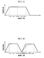
- FIG. 3(a) shows a heating pattern in the heat treatment apparatus 6 when the intermediate chamber 9 and the nitriding chamber 8 have been heated to the same temperature as the aging temperature in the aging chamber 7.
- FIG. 3(b) shows, for comparison, a heating pattern with conventional aging and nitriding chambers that are independent of each other.
- the aging process A is followed by the nitriding process B at the aging temperature without the ring 4 being cooled between those processes A, B.
- a time C is required to cool the ring in the aging chamber after the aging process A
- a time D is required to heat the ring to the nitriding temperature in the nitriding chamber. It can be seen from FIGS. 3(a) and 3(b) that the heat treatment apparatus 6 can dispense with a time (C + D) corresponding to the sum of the times C, D.
- the nitriding process can be carried out uniformly because the nitriding chamber 8 has already been heated to the same temperature as the aging temperature in the aging chamber 7 to make uniform the temperature in the nitriding chamber 8.
- the aging process A is carried out in a temperature range from 480 to 500°C for less than 60 minutes
- the nitriding process B is carried out in a temperature range from 480 to 520°C at a nitriding temperature which is the same as or higher than the aging temperature for a period of time ranging from 45 to 60 minutes.
- the relationship between the heating time in the aging process A and the aged hardness will be described below with reference to FIG. 4. It can be seen from FIG. 4 that if the aging temperature is 480°C, then the aged hardness does not reach a maximum value even when the ring is heated for 60 minutes, and hence the ring is in a sub-aged region. If the aging temperature is 500°C, then the aged hardness reaches a maximum value when the ring is heated for 60 minutes, and the ring is excessively aged and the aged hardness starts to decrease when the ring is heated for more than 60 minutes. If the aging temperature is 520°C, then the ring is excessively aged and the aged hardness starts to decrease when the heating time exceeds 20 minutes.
- the heating time in the aging process A is kept in the sub-aged region, and the aged hardness is caused to reach a maximum value by the heating in the nitriding process B that follows the aging process A. Therefore, if the aging temperature is 500°C, then heating time in the aging process A can be less than 60 minutes.
- the nitriding process B is carried out in a temperature range from 480 to 520°C at a nitriding temperature which is the same as or higher than the aging temperature for a period of time ranging from 45 to 60 minutes. Therefore, the aging of the ring is further performed in addition to the sub-aging in the aging process A until the aged hardness is maximized.
- nitriding temperature The relationship between the nitriding temperature and the heating time will be described below.
- nitrogen penetrates the surface of the ring 4 to form a nitride layer therein to produce hardness.
- the nitrided ring 4 develops such a hardness gradient that the hardness progressively decreases along the depth to which nitrogen goes into the ring 4 from the surface thereof.
- the rings 4 as the laminated ring are used as a belt in transmitting power in a continuously variable transmission.
- the continuously variable transmission undergoes engine braking, the surfaces of the rings 4 suffer a relative slippage.
- the ring 4 is required to have a large surface hardness for the resistance to fatigue due to the slippage, and should desirably have an appropriate hardness gradient from the surface of the ring 4 into the ring 4.
- the table given below shows hardness gradients produced when the ring 4 that has been subjected to the aging process A in the sub-aging region is nitrided in the nitriding process B as shown in FIG. 3(a).
- the hardness gradients in the table include a hardness gradient aa optimum for a belt in transmitting power in a continuously variable transmission, a hardness gradient bb applicable to a belt in transmitting power in a continuously variable transmission, an inadequate hardness gradient cc which is too gradual, and an inadequate hardness gradient dd which is too steep.
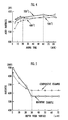
- FIG. 5 shows the relationship (hardness gradient) between the depth from the surface of the ring 4 and the hardness when the ring 4 is subjected to the aging process A in the sub-aging region at 500°C for 40 minutes and then nitrided in the gas soft-nitriding process B at 500°C for 50 minutes according to the heating pattern shown in FIG. 3(a).
- FIG. 5 also shows, for comparison, a hardness gradient achieved when the ring 4 is subjected to the aging process A to obtain peak aged hardness at 500°C for 60 minutes and then nitrided in the gas soft-nitriding process B at 500°C for 50 minutes according to the heating pattern shown in FIG. 3(a).
- FIG. 5 clearly indicates that the surface hardness (indicated by the solid-line curve) of the ring 4 produced by the method according to the embodiment is greater than the surface hardness (indicated by the broken-line curve) of the ring produced by the comparative example, producing a hardness gradient more suitable than with the comparative example in a range from the surface of the ring 4 to the depth of 30 ⁇ m.
- the aging process A is carried out in a temperature range from 450 to 500°C for a period of time ranging from 2 to 3 hours
- the nitriding process B is carried out in a temperature range from 450 to 500°C at a nitriding temperature which is the same as or higher than the aging temperature for a period of time ranging from 30 to 120 minutes.
- FIG. 6 shows a frequency distribution of errors of the measured circumferential lengths of the rings 4 subjected to the aging process A and the nitriding process B with respect to the corrected circumferential lengths. It can be understood from FIG. 6 that the errors of the rings 4 produced in the second mode of the embodiment fall within the range of ⁇ 80 ⁇ m. Therefore, rings 4 of such circumferential lengths that can be fitted together can easily be selected from the classified rings 4 which have been produced according to the present embodiment, and hence the period of time in which the rings 4 are left in stock can be shortened.
- the ring 4 is nitrided to keep the ratio A within the range from 20 to 40 %.
- FIG. 8 shows the relationship between the ratio A (%) of the thickness of the nitride layers 17 to the overall thickness T of the ring 4 and the circumferential length of the ring 4.
- a study of FIG. 8 reveals that when the ratio A is 20 %, the circumferential length of the ring 4 is shortened only by 0.1 mm, and when the ratio A is 40 %, the circumferential length of the ring 4 is increased only by 0.6 mm. Consequently, it can be seen from FIG. 8 that since the ratio A is in the range from 20 to 40 %, the nitrided rings 4 according to the present embodiment suffer very small circumferential length variations and hence are highly dimensionally stable.
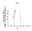
- FIG. 9 shows the relationship between the ratio A (%) of the thickness of the nitride layers 17 to the overall thickness T of the ring 4 and the fatigue-resistant strength of the ring 4.
- the ring 4 is used in a laminated ring as a continuously variable transmission belt, and the fatigue-resistant strength is shown as an indication of the number of times the ring 4 has endured until it is broken.
- the number of times the nitrided ring 4 according to the present embodiment has endured until it is broken is about 4 ⁇ 10 4 or more regardless of the value of the ratio A (%), and hence the nitrided ring 4 has a sufficient level of fatigue-resistant strength.
- FIG. 9 also indicates that if the ratio A (%) exceeds 20 %, then the number of times the nitrided ring 4 has endured until it is broken sharply increases, resulting in an large increase in the fatigue-resistant strength.
- FIG. 10 shows the relationship between the ratio A (%) of the thickness of the nitride layers 17 to the overall thickness T of the ring 4 and the tensile strength of the ring 4. Since the ring 4 is used as in a laminated ring as a continuously variable transmission belt, the tensile strength achieved by the aged layer 18 is required to be 200 kgf/mm 2 or more. When the aging is not sufficient, the tensile strength cannot be achieved. Even when the aging is sufficient, if the ratio A (%) is excessive, relatively reducing the proportion of the aged layer 18, then the tensile strength cannot be achieved either.
- the tensile strength is 200 kgf/mm 2 or more, as shown in FIG. 10.
- the ring 4 when the ring 4 is used in a laminated ring as a continuously variable transmission belt, the ring 4 can satisfy requirements for both the fatigue-resistant strength and the tensile strength.
Landscapes
- Chemical & Material Sciences (AREA)
- Engineering & Computer Science (AREA)
- Mechanical Engineering (AREA)
- Organic Chemistry (AREA)
- Materials Engineering (AREA)
- Metallurgy (AREA)
- Chemical Kinetics & Catalysis (AREA)
- General Engineering & Computer Science (AREA)
- Physics & Mathematics (AREA)
- Thermal Sciences (AREA)
- Crystallography & Structural Chemistry (AREA)
- Heat Treatment Of Articles (AREA)
- Solid-Phase Diffusion Into Metallic Material Surfaces (AREA)
Abstract
Description
| Nitriding temperature (°C) | ||||||
| 460 | 480 | 500 | 520 | 540 | ||
| Heating | 30 | cc | cc | bb | bb | dd |
| time | 45 | cc | bb | aa | aa | dd |
| (min.) | 60 | cc | aa | aa | bb | dd |
| 75 | bb | bb | dd | dd | dd |
Claims (19)
- A method of manufacturing a laminated ring for use as a belt in transmitting power in a continuously variable transmission, comprising the steps of:severing a cylindrical drum, which comprises a sheet of maraging steel with welded opposite ends, into a plurality of rings of predetermined width;rolling said rings to a predetermined length;correcting circumferential lengths of the rings;aging the rings by placing the rings into an aging chamber, heating the aging chamber to a predetermined aging temperature, and keeping the rings at said predetermined aging temperature for a predetermined period of time;thereafter, nitriding said rings by transferring the rings from said aging chamber into a nitriding chamber which is disposed independently of said aging chamber and has been heated to a predetermined nitriding temperature, while maintaining said rings at said aging temperature, keeping said rings at said nitriding temperature in an atmosphere containing ammonia gas for a predetermined period of time, and cooling said rings; andstacking the rings into a laminated ring.
- A method according to claim 1, wherein said step of nitriding said rings comprises the step of gas-nitriding the rings by keeping said rings at said nitriding temperature in an ammonia gas atmosphere for said predetermined period of time or gas-soft-nitriding the rings by keeping said rings at said nitriding temperature in a mixed atmosphere of ammonia and RX gases for said predetermined period of time.
- A method according to claim 1 or 2, wherein said nitriding temperature is equal to or higher than said aging temperature.
- A method according to any preceding claim, wherein said aging chamber is connected to said nitriding chamber through an openable and closable door, and wherein said rings are transferred from said aging chamber into said nitriding chamber through said openable and closable door.
- A method according to any one of claims 1 to 3, wherein said aging chamber is connected through a first openable and closable door to an intermediate chamber which has been heated to a temperature equal to said aging temperature and said nitriding temperature or a temperature intermediate between said aging temperature and said nitriding temperature, and said intermediate chamber is connected to said nitriding chamber through a second openable and closable door, and wherein said rings are transferred from said aging chamber into said nitriding chamber successively through said first openable and closable door, said intermediate chamber, and said second openable and closable door.
- A method according to any preceding claim, wherein the nitrided rings are cooled in said nitriding chamber.
- A method according to any of claims 1 to 5, wherein the nitrided rings are transferred into a cooling chamber which is connected to said nitriding chamber through an openable and closable door, and cooled in said cooling chamber.
- A method according to any preceding claim, wherein said rings are aged in a range in which aged hardness thereof is less than a maximum value, and the aged hardness of the rings reaches the maximum value when the rings are nitrided.
- A method according to claim 8, wherein said rings are aged in a temperature range from 480 to 500°C for less than 60 minutes, and nitrided in a temperature range from 480 to 520°C at the nitriding temperature which is the same as or higher than said aging temperature for a period of time ranging from 45 to 60 minutes.
- A method according to any one of claims 1 to 7, wherein said rings are aged in a temperature range from 450 to 500°C for a period of time ranging from 2 to 3 hours, and nitrided in a temperature range from 450 to 500°C at the nitriding temperature which is the same as or higher than said aging temperature for a period of time ranging from 30 to 120 minutes, so that the errors of the circumferential lengths of the nitrided rings with respect to the corrected circumferential lengths of the rings fall within a predetermined error range.
- A method according to claim 10, wherein said rings are aged such that the error of the circumferential of each of the nitrided rings with respect to the corrected circumferential thereof is in an error range of ± 80 µm.
- A method according to any preceding claim, wherein said rings are nitrided such that the thickness of a nitride layer in the surface of each of the rings is in a range from 20 to 40 % of the overall thickness of the ring.
- Apparatus for the production of heat treated metal rings for use in the manufacture of a laminated ring, comprising means for severing a cylindrical drum which comprises a sheet of maraging steel with welded opposite ends into a plurality of rings of predetermined width, means for rolling said rings to a predetermined length, means for correcting circumferential lengths of the rings and means for aging and nitriding said rings, the apparatus comprising:an aging chamber for housing the rings therein and for being heated to a predetermined aging temperature and keeping the rings at said aging temperature for a predetermined period of time;a nitriding chamber which has been heated to a predetermined nitriding temperature, for housing the rings therein and for keeping said rings at said nitriding temperature in an atmosphere containing at least an ammonia gas for a predetermined period of time; andan openable and closable door, said nitriding chamber being connected to said aging chamber through said openable and closable door.
- A heat treatment apparatus according to claim 13, wherein said nitriding chamber comprises means for gas-nitriding the rings by keeping said rings at said nitriding temperature in an ammonia gas atmosphere for said predetermined period of time or gas-soft-nitriding the rings by keeping said rings at said nitriding temperature in a mixed atmosphere of ammonia and RX gases for said predetermined period of time.
- An apparatus according to claim 13 or 14,
wherein said openable and closable door is vertically movable. - An apparatus according to claim 13, 14 or 15,
further comprising an intermediate chamber which is disposed between said aging chamber and said nitriding chamber and which is heatable to a temperature equal to said aging temperature and said nitriding temperature or a temperature intermediate said aging temperature and said nitriding temperature, wherein said aging chamber, said intermediate chamber, and said nitriding chamber are connected through openable and closable doors, so that said rings can be transferred from said aging chamber through said intermediate chamber into said nitriding chamber. - A heat treatment apparatus according to claim 16, wherein all said openable and closable doors are vertically movable.
- A heat treatment apparatus according to any one of claims 13 to 17, further comprising a cooling chamber connected to said nitriding chamber through an openable and closable door, so that the nitrided rings can be transferred from said nitriding chamber into said cooling chamber and cooled in said cooling chamber.
- A heat treatment apparatus according to claim 18, wherein said openable and closable door is vertically movable.
Priority Applications (1)
| Application Number | Priority Date | Filing Date | Title |
|---|---|---|---|
| EP09168510A EP2119800A1 (en) | 1999-05-28 | 2000-05-26 | Method of manufacturing laminated ring and heat treatment apparatus for use in such method |
Applications Claiming Priority (8)
| Application Number | Priority Date | Filing Date | Title |
|---|---|---|---|
| JP15066799 | 1999-05-28 | ||
| JP15066799 | 1999-05-28 | ||
| JP11151924A JP2000337453A (en) | 1999-05-31 | 1999-05-31 | Endless metal belt manufacturing method |
| JP15192499 | 1999-05-31 | ||
| JP32199999 | 1999-11-12 | ||
| JP32199999A JP2001140019A (en) | 1999-11-12 | 1999-11-12 | Endless metal belt manufacturing method |
| JP2000097233A JP3836296B2 (en) | 1999-05-28 | 2000-03-31 | Endless metal belt manufacturing method and heat treatment apparatus |
| JP2000097233 | 2000-03-31 |
Related Child Applications (1)
| Application Number | Title | Priority Date | Filing Date |
|---|---|---|---|
| EP09168510A Division EP2119800A1 (en) | 1999-05-28 | 2000-05-26 | Method of manufacturing laminated ring and heat treatment apparatus for use in such method |
Publications (3)
| Publication Number | Publication Date |
|---|---|
| EP1055738A2 true EP1055738A2 (en) | 2000-11-29 |
| EP1055738A3 EP1055738A3 (en) | 2004-10-27 |
| EP1055738B1 EP1055738B1 (en) | 2009-09-30 |
Family
ID=27473048
Family Applications (2)
| Application Number | Title | Priority Date | Filing Date |
|---|---|---|---|
| EP00304504A Expired - Lifetime EP1055738B1 (en) | 1999-05-28 | 2000-05-26 | Method of manufacturing laminated ring and heat treatment apparatus for use in such method |
| EP09168510A Withdrawn EP2119800A1 (en) | 1999-05-28 | 2000-05-26 | Method of manufacturing laminated ring and heat treatment apparatus for use in such method |
Family Applications After (1)
| Application Number | Title | Priority Date | Filing Date |
|---|---|---|---|
| EP09168510A Withdrawn EP2119800A1 (en) | 1999-05-28 | 2000-05-26 | Method of manufacturing laminated ring and heat treatment apparatus for use in such method |
Country Status (3)
| Country | Link |
|---|---|
| US (1) | US6631542B1 (en) |
| EP (2) | EP1055738B1 (en) |
| DE (1) | DE60043035D1 (en) |
Cited By (23)
| Publication number | Priority date | Publication date | Assignee | Title |
|---|---|---|---|---|
| FR2823766A1 (en) * | 2001-04-18 | 2002-10-25 | Imphy Ugine Precision | Ring made from maraging steel band for manufacture of a belt for a continuously variable transmission used in a motor vehicle is surface-hardened by pre-stressed shot blasting |
| WO2004076094A1 (en) | 2003-02-26 | 2004-09-10 | Honda Motor Co., Ltd. | Method of manufacturing metal ring for endless metal belt |
| WO2005111253A1 (en) * | 2004-05-19 | 2005-11-24 | Robert Bosch Gmbh | Push belt and manufacturing method therefor |
| WO2006004391A1 (en) * | 2004-06-30 | 2006-01-12 | Robert Bosch Gmbh | Process for forming a ring, forming tool and forming machine for use in such process as well as push belt provided with such a ring |
| WO2006054885A1 (en) * | 2004-11-17 | 2006-05-26 | Robert Bosch Gmbh | Push belt and manufacturing method therefor |
| WO2006104375A1 (en) * | 2005-04-01 | 2006-10-05 | Robert Bosch Gmbh | Quality monitoring method in a push belt manufacturing process |
| EP1669636A3 (en) * | 2004-12-08 | 2007-06-20 | HONDA MOTOR CO., Ltd. | Metal ring for metal belt |
| EP1801245A1 (en) | 2005-12-21 | 2007-06-27 | Robert Bosch Gmbh | Carrier rack for the heat treatment of a metal ring component of a push belt |
| WO2007133062A1 (en) * | 2006-05-16 | 2007-11-22 | Robert Bosch Gmbh | Manufacturing method for a laminated set of metal rings for a pushbelt |
| WO2007145502A1 (en) | 2006-06-12 | 2007-12-21 | Robert Bosch Gmbh | Manufacturing method for making thin metal rings |
| WO2009056169A1 (en) * | 2007-10-31 | 2009-05-07 | Robert Bosch Gmbh | Drive belt ring component and manufacturing method therefor |
| WO2009134119A1 (en) | 2008-04-28 | 2009-11-05 | Robert Bosch Gmbh | Drive belt ring component and manufacturing method and maraging steel base material therefor |
| US7673502B2 (en) | 2004-03-01 | 2010-03-09 | Jatco Ltd | Inspection of a continuously variable transmission belt member |
| NL1037364C2 (en) * | 2009-10-06 | 2011-04-07 | Bosch Gmbh Robert | Drive belt provided with a laminated set of steel rings. |
| CN102015148A (en) * | 2008-04-28 | 2011-04-13 | 罗伯特·博世有限公司 | Manufacturing method for a drive belt ring component |
| WO2011076397A1 (en) | 2009-12-23 | 2011-06-30 | Robert Bosch Gmbh | Drive belt provided with a steel ring |
| WO2012083975A1 (en) | 2010-12-20 | 2012-06-28 | Robert Bosch G.M.B.H. | Heat treatment process for a manufacturing process of a drive belt metal ring component |
| WO2012083974A1 (en) | 2010-12-20 | 2012-06-28 | Robert Bosch G.M.B.H. | Heat treatment process for a manufacturing process of a drive belt metal ring component |
| WO2013002633A1 (en) | 2011-06-30 | 2013-01-03 | Robert Bosch Gmbh | Manufacturing method for a drive belt ring component |
| CN103537713A (en) * | 2013-10-29 | 2014-01-29 | 贵州航天新力铸锻有限责任公司 | Nuclear power station vapor generator vertical bracing semisphere lining manufacturing method |
| CN104439949A (en) * | 2014-11-13 | 2015-03-25 | 江苏省常熟环通实业有限公司 | Lengthened welded steel tube manufacturing method |
| CN108971585A (en) * | 2018-08-24 | 2018-12-11 | 沈阳富创精密设备有限公司 | The processing technology of the big annular workpieces of equal slabs processing aluminum alloy strip countersunk head |
| CN110586746A (en) * | 2019-09-29 | 2019-12-20 | 宏源精工车轮股份有限公司 | Check ring processing technology |
Families Citing this family (18)
| Publication number | Priority date | Publication date | Assignee | Title |
|---|---|---|---|---|
| DE10159568A1 (en) * | 2001-12-04 | 2003-06-12 | Zf Batavia Llc | Procedure for checking the manufacturing quality of push links in push link belts |
| JP3580303B2 (en) * | 2002-08-30 | 2004-10-20 | 日産自動車株式会社 | Endless metal belt manufacturing method and manufacturing apparatus |
| AU2003266561A1 (en) * | 2002-09-24 | 2004-04-19 | Honda Giken Kogyo Kabushiki Kaisha | Method of nitriding metal ring and apparatus therefor |
| US7294077B2 (en) * | 2004-02-24 | 2007-11-13 | General Motors Corporation | CVT belt with chromium nitride coating |
| WO2011077579A1 (en) * | 2009-12-25 | 2011-06-30 | トヨタ自動車株式会社 | Method for producing laminated ring |
| WO2011135624A1 (en) * | 2010-04-28 | 2011-11-03 | トヨタ自動車株式会社 | Metal ring and method for producing same |
| CN102528385B (en) * | 2010-12-24 | 2013-10-23 | 沈阳黎明航空发动机(集团)有限责任公司 | Method for compensating elasticity value of elastic ring |
| DE102013006009B3 (en) * | 2013-04-09 | 2014-07-31 | Boa Balg- Und Kompensatoren-Technologie Gmbh | Producing bellows of austenitic stainless steel, includes transforming single or multilayer sleeve by hydraulic transformation to form bellows, cleaning bellows in environment of e.g. carbon and/or nitrogen atmosphere and hardening |
| JP6036574B2 (en) * | 2013-06-25 | 2016-11-30 | トヨタ自動車株式会社 | Manufacturing method of laminated ring |
| WO2015087869A1 (en) | 2013-12-12 | 2015-06-18 | 愛知製鋼株式会社 | Ring member for cvt and method for producing same |
| CN105690042B (en) * | 2016-04-11 | 2017-11-24 | 贵州遵义驰宇精密机电制造有限公司 | A kind of processing method of semicircle press strip |
| DE102016107240A1 (en) * | 2016-04-19 | 2017-10-19 | Hoerbiger Antriebstechnik Holding Gmbh | Method for producing a sliding sleeve for a manual transmission synchronous assembly and produced by the method sliding sleeve |
| CN106637056A (en) * | 2017-01-16 | 2017-05-10 | 苏州诺迅汽车零部件有限公司 | Process for nitriding nozzle ring weld assemblies |
| CN107263031A (en) * | 2017-06-26 | 2017-10-20 | 山东美陵化工设备股份有限公司 | Cylinder is without pre-bending edge rolling moulding process |
| CN109967974B (en) * | 2019-02-26 | 2021-11-26 | 安徽森钢建筑工程有限公司 | Method for reducing welding stress of steel structure product |
| CN112276494A (en) * | 2020-10-28 | 2021-01-29 | 上海航天精密机械研究所 | Method for integrally processing and manufacturing weak-rigidity thin-wall ring frame suitable for spacecraft |
| CN112935708A (en) * | 2020-12-14 | 2021-06-11 | 伊莱特能源装备股份有限公司 | Manufacturing process of ultra-large wheel belt forge piece |
| CN115008135B (en) * | 2022-06-21 | 2023-05-26 | 湖南华菱湘潭钢铁有限公司 | Production method of large-wall-thickness large-caliber longitudinal submerged arc welded pipe L555M |
Family Cites Families (24)
| Publication number | Priority date | Publication date | Assignee | Title |
|---|---|---|---|---|
| US3598381A (en) * | 1969-02-26 | 1971-08-10 | Holcroft & Co | Continuous carburizing furnace |
| GB1414619A (en) * | 1971-10-27 | 1975-11-19 | Actric Ltd | Heat treatment furnaces and methods of heat treatment |
| GB2027062B (en) * | 1978-07-12 | 1982-08-25 | Honda Motor Co Ltd | Continuous process for brazing and nitriding |
| US4225121A (en) * | 1979-03-23 | 1980-09-30 | Holcroft | Energy efficient heat-treating furnace system |
| US4417927A (en) * | 1982-03-29 | 1983-11-29 | General Electric Company | Steel nitriding method and apparatus |
| JPS60204825A (en) * | 1984-03-29 | 1985-10-16 | Mitsubishi Heavy Ind Ltd | Manufacture of steel belt |
| JPS61266844A (en) * | 1985-05-18 | 1986-11-26 | Honda Motor Co Ltd | Laminated metal belt for torque transmission |
| US4760745A (en) * | 1986-12-05 | 1988-08-02 | Mag Dev Inc. | Magnetoelastic torque transducer |
| JPS63195216A (en) * | 1987-02-10 | 1988-08-12 | Kobe Steel Ltd | Production of endless belt hoop |
| US5273585A (en) * | 1990-03-27 | 1993-12-28 | Mazda Motor Corporation | Heat-treating apparatus |
| US5194097A (en) * | 1990-10-01 | 1993-03-16 | Daidousanso Co., Ltd. | Method of nitriding steel and heat treat furnaces used therein |
| US5112030A (en) * | 1990-10-01 | 1992-05-12 | Daidousanso Co., Ltd. | Heat treat furnace for fluorinating steel material |
| US5143558A (en) * | 1991-03-11 | 1992-09-01 | Thermo Process Systems Inc. | Method of heat treating metal parts in an integrated continuous and batch furnace system |
| US5402994A (en) * | 1992-01-15 | 1995-04-04 | Aichelin Gmbh | Device for heat-treating metal workpieces |
| US5393488A (en) * | 1993-08-06 | 1995-02-28 | General Electric Company | High strength, high fatigue structural steel |
| JPH10121130A (en) * | 1996-10-09 | 1998-05-12 | Honda Motor Co Ltd | Manufacturing method of endless metal ring |
| US5928604A (en) * | 1996-11-27 | 1999-07-27 | Caterpillar Inc. | Automated system for carburizing a component |
| JP3186678B2 (en) * | 1997-12-10 | 2001-07-11 | 日産自動車株式会社 | Manufacturing method of metal belt for belt type continuously variable transmission |
| JP3439132B2 (en) * | 1998-09-10 | 2003-08-25 | エア・ウォーター株式会社 | Method for nitriding maraging steel and maraging steel product obtained thereby |
| US6309474B1 (en) * | 1999-03-04 | 2001-10-30 | Honda Giken Kogyo Kabushiki Kaisha | Process for producing maraging steel |
| US6379473B1 (en) * | 1999-05-28 | 2002-04-30 | Honda Giken Kogyo Kabushiki Kaisha | Method of manufacturing laminated ring using molten salt composition |
| JP4308368B2 (en) * | 1999-06-07 | 2009-08-05 | 本田技研工業株式会社 | Method for producing endless metal belt |
| US6318140B1 (en) * | 1999-10-08 | 2001-11-20 | Honda Giken Kogyo Kabushiki Kaisha | Method of manufacturing laminated ring and apparatus for measuring circumferential length difference of ring in such method |
| DE60044487D1 (en) * | 1999-10-22 | 2010-07-15 | Honda Motor Co Ltd | Process for producing a laminated ring |
-
2000
- 2000-05-26 EP EP00304504A patent/EP1055738B1/en not_active Expired - Lifetime
- 2000-05-26 DE DE60043035T patent/DE60043035D1/en not_active Expired - Lifetime
- 2000-05-26 EP EP09168510A patent/EP2119800A1/en not_active Withdrawn
- 2000-05-26 US US09/580,920 patent/US6631542B1/en not_active Expired - Fee Related
Cited By (32)
| Publication number | Priority date | Publication date | Assignee | Title |
|---|---|---|---|---|
| FR2823766A1 (en) * | 2001-04-18 | 2002-10-25 | Imphy Ugine Precision | Ring made from maraging steel band for manufacture of a belt for a continuously variable transmission used in a motor vehicle is surface-hardened by pre-stressed shot blasting |
| CN100386165C (en) * | 2003-02-26 | 2008-05-07 | 本田技研工业株式会社 | Manufacturing method of metal ring for endless metal belt |
| WO2004076094A1 (en) | 2003-02-26 | 2004-09-10 | Honda Motor Co., Ltd. | Method of manufacturing metal ring for endless metal belt |
| US7168279B2 (en) | 2003-02-26 | 2007-01-30 | Honda Motor Co., Ltd. | Method of manufacturing metal ring for endless metal belt |
| US7673502B2 (en) | 2004-03-01 | 2010-03-09 | Jatco Ltd | Inspection of a continuously variable transmission belt member |
| WO2005111253A1 (en) * | 2004-05-19 | 2005-11-24 | Robert Bosch Gmbh | Push belt and manufacturing method therefor |
| WO2006004391A1 (en) * | 2004-06-30 | 2006-01-12 | Robert Bosch Gmbh | Process for forming a ring, forming tool and forming machine for use in such process as well as push belt provided with such a ring |
| WO2006054885A1 (en) * | 2004-11-17 | 2006-05-26 | Robert Bosch Gmbh | Push belt and manufacturing method therefor |
| CN101061329B (en) * | 2004-11-17 | 2010-08-11 | 罗伯特·博世有限公司 | Press belt and its manufacturing method |
| US8062159B2 (en) | 2004-12-08 | 2011-11-22 | Honda Motor Co., Ltd. | Metal ring for metal belt |
| EP1669636A3 (en) * | 2004-12-08 | 2007-06-20 | HONDA MOTOR CO., Ltd. | Metal ring for metal belt |
| WO2006104375A1 (en) * | 2005-04-01 | 2006-10-05 | Robert Bosch Gmbh | Quality monitoring method in a push belt manufacturing process |
| EP1801245A1 (en) | 2005-12-21 | 2007-06-27 | Robert Bosch Gmbh | Carrier rack for the heat treatment of a metal ring component of a push belt |
| WO2007133062A1 (en) * | 2006-05-16 | 2007-11-22 | Robert Bosch Gmbh | Manufacturing method for a laminated set of metal rings for a pushbelt |
| WO2007145502A1 (en) | 2006-06-12 | 2007-12-21 | Robert Bosch Gmbh | Manufacturing method for making thin metal rings |
| WO2009056169A1 (en) * | 2007-10-31 | 2009-05-07 | Robert Bosch Gmbh | Drive belt ring component and manufacturing method therefor |
| WO2009134119A1 (en) | 2008-04-28 | 2009-11-05 | Robert Bosch Gmbh | Drive belt ring component and manufacturing method and maraging steel base material therefor |
| CN102015148A (en) * | 2008-04-28 | 2011-04-13 | 罗伯特·博世有限公司 | Manufacturing method for a drive belt ring component |
| CN102016348A (en) * | 2008-04-28 | 2011-04-13 | 罗伯特·博世有限公司 | Drive belt ring component and manufacturing method and maraging steel base material therefor |
| CN102016348B (en) * | 2008-04-28 | 2016-01-20 | 罗伯特·博世有限公司 | Drive belt ring parts and manufacture method and martensite ag(e)ing steel substrate thereof |
| CN102015148B (en) * | 2008-04-28 | 2013-11-20 | 罗伯特·博世有限公司 | Manufacturing method for a drive belt ring component |
| NL1037364C2 (en) * | 2009-10-06 | 2011-04-07 | Bosch Gmbh Robert | Drive belt provided with a laminated set of steel rings. |
| WO2011043648A1 (en) * | 2009-10-06 | 2011-04-14 | Robert Bosch Gmbh | Drive belt provided with a laminated set of steel rings |
| WO2011076397A1 (en) | 2009-12-23 | 2011-06-30 | Robert Bosch Gmbh | Drive belt provided with a steel ring |
| WO2012083975A1 (en) | 2010-12-20 | 2012-06-28 | Robert Bosch G.M.B.H. | Heat treatment process for a manufacturing process of a drive belt metal ring component |
| WO2012083974A1 (en) | 2010-12-20 | 2012-06-28 | Robert Bosch G.M.B.H. | Heat treatment process for a manufacturing process of a drive belt metal ring component |
| WO2013002633A1 (en) | 2011-06-30 | 2013-01-03 | Robert Bosch Gmbh | Manufacturing method for a drive belt ring component |
| CN103537713A (en) * | 2013-10-29 | 2014-01-29 | 贵州航天新力铸锻有限责任公司 | Nuclear power station vapor generator vertical bracing semisphere lining manufacturing method |
| CN103537713B (en) * | 2013-10-29 | 2015-11-04 | 贵州航天新力铸锻有限责任公司 | The manufacture method of nuclear power station steam generator vertical support hemisphere face lining |
| CN104439949A (en) * | 2014-11-13 | 2015-03-25 | 江苏省常熟环通实业有限公司 | Lengthened welded steel tube manufacturing method |
| CN108971585A (en) * | 2018-08-24 | 2018-12-11 | 沈阳富创精密设备有限公司 | The processing technology of the big annular workpieces of equal slabs processing aluminum alloy strip countersunk head |
| CN110586746A (en) * | 2019-09-29 | 2019-12-20 | 宏源精工车轮股份有限公司 | Check ring processing technology |
Also Published As
| Publication number | Publication date |
|---|---|
| US6631542B1 (en) | 2003-10-14 |
| EP1055738A3 (en) | 2004-10-27 |
| EP1055738B1 (en) | 2009-09-30 |
| EP2119800A1 (en) | 2009-11-18 |
| DE60043035D1 (en) | 2009-11-12 |
Similar Documents
| Publication | Publication Date | Title |
|---|---|---|
| US6631542B1 (en) | Method of manufacturing laminated ring and heat treatment apparatus for use in such method | |
| US6733600B2 (en) | Nitrided maraging steel and method of manufacture thereof | |
| EP1544317A1 (en) | Method of nitriding metal ring and apparatus therefor | |
| US9982749B2 (en) | Method for manufacturing endless metal belt, endless metal belt, and belt-type continuously variable transmission | |
| US6379473B1 (en) | Method of manufacturing laminated ring using molten salt composition | |
| EP1815160B1 (en) | Push belt and manufacturing method therefor | |
| KR20110020948A (en) | Heat treatment method for metal ring components for drive belts | |
| JP3630299B2 (en) | Method for manufacturing endless ring for metal belt of continuously variable transmission | |
| US20160312854A1 (en) | Cvt ring member and method for manufacturing the same | |
| JP3836296B2 (en) | Endless metal belt manufacturing method and heat treatment apparatus | |
| JP2000337453A (en) | Endless metal belt manufacturing method | |
| JP2001140019A (en) | Endless metal belt manufacturing method | |
| JP3823875B2 (en) | Nitriding method for maraging steel and belt for belt-type continuously variable transmission nitrided by the method | |
| JP3986996B2 (en) | Method for nitriding metal ring | |
| WO2012083974A1 (en) | Heat treatment process for a manufacturing process of a drive belt metal ring component | |
| US20190331197A1 (en) | Endless metal ring and method of producing the same | |
| JPS62192528A (en) | Method for manufacturing maraging steel members with excellent wear resistance and fatigue strength | |
| US20040244873A1 (en) | Steel belt comprising martensitic steel and method for manufacturing hoop for continuously variable transmission using said steel belt | |
| JP3986995B2 (en) | Metal ring nitriding equipment | |
| JP2017509788A (en) | Drive belt metal ring component manufacturing method and metal ring manufactured according to the manufacturing method | |
| JPH11200010A (en) | Surface treatment method of metal multilayer belt for automobile | |
| JP4308368B2 (en) | Method for producing endless metal belt | |
| JP4084228B2 (en) | Metal ring heat treatment method | |
| JP6008976B2 (en) | Heat treatment process in manufacturing method of drive belt metal ring element | |
| JP2001123226A (en) | Endless metal belt manufacturing method |
Legal Events
| Date | Code | Title | Description |
|---|---|---|---|
| PUAI | Public reference made under article 153(3) epc to a published international application that has entered the european phase |
Free format text: ORIGINAL CODE: 0009012 |
|
| AK | Designated contracting states |
Kind code of ref document: A2 Designated state(s): AT BE CH CY DE DK ES FI FR GB GR IE IT LI LU MC NL PT SE |
|
| AX | Request for extension of the european patent |
Free format text: AL;LT;LV;MK;RO;SI |
|
| PUAL | Search report despatched |
Free format text: ORIGINAL CODE: 0009013 |
|
| AK | Designated contracting states |
Kind code of ref document: A3 Designated state(s): AT BE CH CY DE DK ES FI FR GB GR IE IT LI LU MC NL PT SE |
|
| AX | Request for extension of the european patent |
Extension state: AL LT LV MK RO SI |
|
| RIC1 | Information provided on ipc code assigned before grant |
Ipc: 7F 16G 5/16 B Ipc: 7B 23P 15/00 B Ipc: 7C 23C 8/50 B Ipc: 7C 23C 8/26 B Ipc: 7C 21D 9/40 A |
|
| 17P | Request for examination filed |
Effective date: 20050425 |
|
| AKX | Designation fees paid |
Designated state(s): DE FR GB NL |
|
| 17Q | First examination report despatched |
Effective date: 20080222 |
|
| GRAP | Despatch of communication of intention to grant a patent |
Free format text: ORIGINAL CODE: EPIDOSNIGR1 |
|
| RIN1 | Information on inventor provided before grant (corrected) |
Inventor name: KARASAWA, HIROSHI Inventor name: NAKAJIMA, KATSUYUKI Inventor name: IMAI, HITOSHI |
|
| GRAS | Grant fee paid |
Free format text: ORIGINAL CODE: EPIDOSNIGR3 |
|
| RIN1 | Information on inventor provided before grant (corrected) |
Inventor name: IMAI, HITOSHI Inventor name: NAKAJIMA, KATSUYUKI Inventor name: KARASAWA, HITOSHI |
|
| GRAA | (expected) grant |
Free format text: ORIGINAL CODE: 0009210 |
|
| AK | Designated contracting states |
Kind code of ref document: B1 Designated state(s): DE FR GB NL |
|
| REG | Reference to a national code |
Ref country code: GB Ref legal event code: FG4D |
|
| REF | Corresponds to: |
Ref document number: 60043035 Country of ref document: DE Date of ref document: 20091112 Kind code of ref document: P |
|
| PGFP | Annual fee paid to national office [announced via postgrant information from national office to epo] |
Ref country code: FR Payment date: 20100525 Year of fee payment: 11 |
|
| PLBE | No opposition filed within time limit |
Free format text: ORIGINAL CODE: 0009261 |
|
| STAA | Information on the status of an ep patent application or granted ep patent |
Free format text: STATUS: NO OPPOSITION FILED WITHIN TIME LIMIT |
|
| PGFP | Annual fee paid to national office [announced via postgrant information from national office to epo] |
Ref country code: NL Payment date: 20100501 Year of fee payment: 11 |
|
| 26N | No opposition filed |
Effective date: 20100701 |
|
| PGFP | Annual fee paid to national office [announced via postgrant information from national office to epo] |
Ref country code: GB Payment date: 20110525 Year of fee payment: 12 |
|
| PGFP | Annual fee paid to national office [announced via postgrant information from national office to epo] |
Ref country code: DE Payment date: 20110518 Year of fee payment: 12 |
|
| REG | Reference to a national code |
Ref country code: NL Ref legal event code: V1 Effective date: 20111201 |
|
| PG25 | Lapsed in a contracting state [announced via postgrant information from national office to epo] |
Ref country code: NL Free format text: LAPSE BECAUSE OF NON-PAYMENT OF DUE FEES Effective date: 20111201 |
|
| REG | Reference to a national code |
Ref country code: FR Ref legal event code: ST Effective date: 20120131 |
|
| PG25 | Lapsed in a contracting state [announced via postgrant information from national office to epo] |
Ref country code: FR Free format text: LAPSE BECAUSE OF NON-PAYMENT OF DUE FEES Effective date: 20110531 |
|
| GBPC | Gb: european patent ceased through non-payment of renewal fee |
Effective date: 20120526 |
|
| REG | Reference to a national code |
Ref country code: DE Ref legal event code: R119 Ref document number: 60043035 Country of ref document: DE Effective date: 20121201 |
|
| PG25 | Lapsed in a contracting state [announced via postgrant information from national office to epo] |
Ref country code: GB Free format text: LAPSE BECAUSE OF NON-PAYMENT OF DUE FEES Effective date: 20120526 |
|
| PG25 | Lapsed in a contracting state [announced via postgrant information from national office to epo] |
Ref country code: DE Free format text: LAPSE BECAUSE OF NON-PAYMENT OF DUE FEES Effective date: 20121201 |