EP1055115B1 - Method and device for identification of a type of material in an object and utilization therefor - Google Patents
Method and device for identification of a type of material in an object and utilization therefor Download PDFInfo
- Publication number
- EP1055115B1 EP1055115B1 EP99909425A EP99909425A EP1055115B1 EP 1055115 B1 EP1055115 B1 EP 1055115B1 EP 99909425 A EP99909425 A EP 99909425A EP 99909425 A EP99909425 A EP 99909425A EP 1055115 B1 EP1055115 B1 EP 1055115B1
- Authority
- EP
- European Patent Office
- Prior art keywords
- article
- filters
- detector
- sequence
- measured values
- Prior art date
- Legal status (The legal status is an assumption and is not a legal conclusion. Google has not performed a legal analysis and makes no representation as to the accuracy of the status listed.)
- Expired - Lifetime
Links
- 239000000463 material Substances 0.000 title claims abstract description 68
- 238000000034 method Methods 0.000 title claims abstract description 35
- 230000005855 radiation Effects 0.000 claims abstract description 28
- 230000005540 biological transmission Effects 0.000 claims abstract description 26
- 229920003023 plastic Polymers 0.000 claims abstract description 24
- 239000004033 plastic Substances 0.000 claims abstract description 24
- 239000011521 glass Substances 0.000 claims abstract description 13
- 230000003595 spectral effect Effects 0.000 claims abstract description 12
- 238000010219 correlation analysis Methods 0.000 claims abstract description 9
- 238000013179 statistical model Methods 0.000 claims abstract description 6
- 230000001678 irradiating effect Effects 0.000 claims abstract 2
- 239000012780 transparent material Substances 0.000 claims abstract 2
- -1 polyethylene terephthalate Polymers 0.000 claims description 25
- 238000004458 analytical method Methods 0.000 claims description 16
- 238000005259 measurement Methods 0.000 claims description 13
- 239000004698 Polyethylene Substances 0.000 claims description 12
- 229920000573 polyethylene Polymers 0.000 claims description 12
- 239000005020 polyethylene terephthalate Substances 0.000 claims description 12
- 229920000139 polyethylene terephthalate Polymers 0.000 claims description 12
- 239000004743 Polypropylene Substances 0.000 claims description 10
- 229920001155 polypropylene Polymers 0.000 claims description 10
- 239000013598 vector Substances 0.000 claims description 9
- 229920000515 polycarbonate Polymers 0.000 claims description 8
- 239000004417 polycarbonate Substances 0.000 claims description 8
- 239000004793 Polystyrene Substances 0.000 claims description 7
- 239000011112 polyethylene naphthalate Substances 0.000 claims description 7
- 239000004800 polyvinyl chloride Substances 0.000 claims description 7
- 229920003207 poly(ethylene-2,6-naphthalate) Polymers 0.000 claims description 6
- 239000004952 Polyamide Substances 0.000 claims description 5
- 108010076504 Protein Sorting Signals Proteins 0.000 claims description 5
- XECAHXYUAAWDEL-UHFFFAOYSA-N acrylonitrile butadiene styrene Chemical compound C=CC=C.C=CC#N.C=CC1=CC=CC=C1 XECAHXYUAAWDEL-UHFFFAOYSA-N 0.000 claims description 5
- 239000004676 acrylonitrile butadiene styrene Substances 0.000 claims description 5
- 229920000122 acrylonitrile butadiene styrene Polymers 0.000 claims description 5
- 229920003229 poly(methyl methacrylate) Polymers 0.000 claims description 5
- 229920002647 polyamide Polymers 0.000 claims description 5
- 239000004926 polymethyl methacrylate Substances 0.000 claims description 5
- 239000004814 polyurethane Substances 0.000 claims description 5
- 229920002635 polyurethane Polymers 0.000 claims description 5
- 238000004422 calculation algorithm Methods 0.000 claims description 4
- 229920002223 polystyrene Polymers 0.000 claims description 4
- 229920000915 polyvinyl chloride Polymers 0.000 claims description 4
- 230000000903 blocking effect Effects 0.000 claims description 3
- 230000000694 effects Effects 0.000 claims description 2
- 238000001914 filtration Methods 0.000 claims description 2
- 238000010239 partial least squares discriminant analysis Methods 0.000 claims 2
- 238000012360 testing method Methods 0.000 description 11
- 238000001514 detection method Methods 0.000 description 9
- 239000007789 gas Substances 0.000 description 5
- 238000009434 installation Methods 0.000 description 5
- 230000002093 peripheral effect Effects 0.000 description 5
- RZVAJINKPMORJF-UHFFFAOYSA-N Acetaminophen Chemical compound CC(=O)NC1=CC=C(O)C=C1 RZVAJINKPMORJF-UHFFFAOYSA-N 0.000 description 4
- 238000012986 modification Methods 0.000 description 4
- 230000004048 modification Effects 0.000 description 4
- 239000005297 pyrex Substances 0.000 description 4
- 238000004611 spectroscopical analysis Methods 0.000 description 4
- 238000000354 decomposition reaction Methods 0.000 description 3
- 238000001228 spectrum Methods 0.000 description 3
- 238000000862 absorption spectrum Methods 0.000 description 2
- 230000000875 corresponding effect Effects 0.000 description 2
- 238000013461 design Methods 0.000 description 2
- 239000000523 sample Substances 0.000 description 2
- YBNMDCCMCLUHBL-UHFFFAOYSA-N (2,5-dioxopyrrolidin-1-yl) 4-pyren-1-ylbutanoate Chemical compound C=1C=C(C2=C34)C=CC3=CC=CC4=CC=C2C=1CCCC(=O)ON1C(=O)CCC1=O YBNMDCCMCLUHBL-UHFFFAOYSA-N 0.000 description 1
- 108091081062 Repeated sequence (DNA) Proteins 0.000 description 1
- 239000004411 aluminium Substances 0.000 description 1
- XAGFODPZIPBFFR-UHFFFAOYSA-N aluminium Chemical compound [Al] XAGFODPZIPBFFR-UHFFFAOYSA-N 0.000 description 1
- 229910052782 aluminium Inorganic materials 0.000 description 1
- 238000004164 analytical calibration Methods 0.000 description 1
- 238000013528 artificial neural network Methods 0.000 description 1
- 238000007635 classification algorithm Methods 0.000 description 1
- 239000003086 colorant Substances 0.000 description 1
- 238000005056 compaction Methods 0.000 description 1
- 239000012141 concentrate Substances 0.000 description 1
- 230000002596 correlated effect Effects 0.000 description 1
- 238000005100 correlation spectroscopy Methods 0.000 description 1
- 230000001419 dependent effect Effects 0.000 description 1
- 238000010586 diagram Methods 0.000 description 1
- 238000011156 evaluation Methods 0.000 description 1
- 238000009499 grossing Methods 0.000 description 1
- 238000004519 manufacturing process Methods 0.000 description 1
- 239000010812 mixed waste Substances 0.000 description 1
- 238000003333 near-infrared imaging Methods 0.000 description 1
- 238000006396 nitration reaction Methods 0.000 description 1
- 230000003287 optical effect Effects 0.000 description 1
- 229920000642 polymer Polymers 0.000 description 1
- 238000000513 principal component analysis Methods 0.000 description 1
- 238000012545 processing Methods 0.000 description 1
- 238000004451 qualitative analysis Methods 0.000 description 1
- 239000002994 raw material Substances 0.000 description 1
- 238000004064 recycling Methods 0.000 description 1
- 238000007670 refining Methods 0.000 description 1
- 239000007787 solid Substances 0.000 description 1
- 239000000126 substance Substances 0.000 description 1
Images

Classifications
-
- G—PHYSICS
- G01—MEASURING; TESTING
- G01N—INVESTIGATING OR ANALYSING MATERIALS BY DETERMINING THEIR CHEMICAL OR PHYSICAL PROPERTIES
- G01N21/00—Investigating or analysing materials by the use of optical means, i.e. using sub-millimetre waves, infrared, visible or ultraviolet light
- G01N21/17—Systems in which incident light is modified in accordance with the properties of the material investigated
- G01N21/25—Colour; Spectral properties, i.e. comparison of effect of material on the light at two or more different wavelengths or wavelength bands
- G01N21/31—Investigating relative effect of material at wavelengths characteristic of specific elements or molecules, e.g. atomic absorption spectrometry
- G01N21/35—Investigating relative effect of material at wavelengths characteristic of specific elements or molecules, e.g. atomic absorption spectrometry using infrared light
- G01N21/3563—Investigating relative effect of material at wavelengths characteristic of specific elements or molecules, e.g. atomic absorption spectrometry using infrared light for analysing solids; Preparation of samples therefor
-
- B—PERFORMING OPERATIONS; TRANSPORTING
- B07—SEPARATING SOLIDS FROM SOLIDS; SORTING
- B07C—POSTAL SORTING; SORTING INDIVIDUAL ARTICLES, OR BULK MATERIAL FIT TO BE SORTED PIECE-MEAL, e.g. BY PICKING
- B07C5/00—Sorting according to a characteristic or feature of the articles or material being sorted, e.g. by control effected by devices which detect or measure such characteristic or feature; Sorting by manually actuated devices, e.g. switches
- B07C5/34—Sorting according to other particular properties
- B07C5/3416—Sorting according to other particular properties according to radiation transmissivity, e.g. for light, x-rays, particle radiation
-
- G—PHYSICS
- G01—MEASURING; TESTING
- G01N—INVESTIGATING OR ANALYSING MATERIALS BY DETERMINING THEIR CHEMICAL OR PHYSICAL PROPERTIES
- G01N2201/00—Features of devices classified in G01N21/00
- G01N2201/12—Circuits of general importance; Signal processing
- G01N2201/129—Using chemometrical methods
- G01N2201/1293—Using chemometrical methods resolving multicomponent spectra
Definitions
- the present invention relates to a method and an apparatus for identifying a type of material in a physical article, such as a wholly or partly transparent bottle of plastics or glass, the article in a continuous or discontinuous movement being caused to pass through a detector station, by means of the detector station illuminating the article by light rays from an infrared radiation source, detecting light rays which nonabsorbed have passed through the article, and thereafter carrying out a correlation analysis of such detected light rays, as is set forth in the preamble of the enclosed claims 1 and 17.
- VAN DEN BROEK W H A M ET AL. "Identification of Plastics among Nonplastics in Mixed Waste by Remote Sensing Near-Infrared Imaging Spectroscopy. 1. Image Improvement and Analysis by Singular Value Decomposition" ANAL. CHEM., vol. 67, no. 20, 15 October 1995, pages 3753-3759 , XP000541459 Washington, DC, US.
- the article discloses installation of a near-IR camera in an experimental setup for real-time plastic identification.
- Singular value decomposition (SVD) is used for qualitative analysis and substantial improvement of the measured multivariate images.
- Obtained score plots provide spatial correlations between different pixel structures caused by sample material on the one hand and image artifacts on the other.
- the score plots are used as a tool to optimize experimental setup and image quality.
- the improved images were offered to a new classification algorithm called multivariate image rank analysis, based on SVD. Filtering is done by using filters of a same material, although with different colours or wavelength pass bands.
- correlation spectroscopy is known in connection with the measurement of gases, both for the detection of gases and concentration measurement.
- the gas to be analysed is used as a filter.
- the object of the present invention is to use a similar technique for the detection of plastic materials.
- Absorption spectra of solid substances such as plastics are very different from the absorption spectra of gases. Whilst gases have very many, very fine lines in the spectrum, plastic materials have fewer and broader lines, so that as a rule the spectra of different materials have more or less overlapping lines. In such a situation, more information is obtained about the material to be identified by measuring the degree of spectral overlapping with a number of different plastic materials.
- An advantageous application of the method and apparatus would be to use them in a reverse vending machine to identify and sort bottles of different material types.
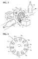
- the apparatus has a detector station, including an infrared radiation source 1 which has a hot element 2 that emits infrared rays 3, optionally via a mirror 4.
- the radiation source 1 has an illuminator aperture 5 and the infrared beam is guided towards a filter device 6, preferably consisting of a rotatable, round or polygonal disc 7 which via a rotation shaft 8 is caused to rotate by a motor 9 which via cable connection 12, 13 is supplied with electric drive current under the control of a microprocessor 11.
- the light filter device 6 is provided with a plurality of different light filters 10. In a preferred test version, as shown in Fig. 3, the chosen number of light filters is ten.
- the filters 10 provided on the filter device in the form of a wheel or a rotating disc consist at least in part of a number of light-transparent pieces of different types of plastic material, e.g., selected from the material group consisting of polyethylene terephthalate, polyethylene naphthalate, polyvinyl chloride, polypropylene, polyethylene, polystyrene, acrylonitrile-butadiene-styrene copolymer, polymethyl methacrylate, polyamide, polyurethane, polysulphonate and polycarbonate.
- at least one of the filters may optionally be of glass, e.g., Pyrex ® glass.
- Fig. 1 shows the order of the envelope filter 14, the filter device 6 and the diaphragm 15 preferred at present, it should be appreciated that their position relative to one another may de different. Similarly, it is conceivable that one or more of these components may, e.g., be positioned on the opposite side of the conveyor 17. Furthermore, it is possible that, e.g., the diaphragm 15 and the envelope filter 14 may made in the form of a single unit, or that the filter device 6 and the diaphragm 15 may be combined into one unit.
- the filter 10 1 forms a reference filter which preferably is made of a spectrally uniform or material-free diaphragm 16 (see Fig. 2).
- the filter 10 2 is of an opaque material, e.g., completely black, thus preventing the passage of light rays therethrough. Due to its area-limiting light ray penetrability through the diaphragm or aperture 16, the filter 10 1 produces a signal peak reference value in the sequences of measured values. The light ray impenetrability of the filter 10 2 will create a trough reference value in the sequence of measured values.
- the other filters 10 3 , 10 4 , 10 5 , 10 6 , 10 7 , 10 8 , 10 9 and 10 10 were chosen from materials consisting respectively of polycarbonate (PC), polystyrene (PS), polyethylene terephthalate (PET), glass (Pyrex ® glass), polyvinyl chloride (PVC), polyethylene (PE), polypropylene (PP) and polyethylene with an applied film, here designated UK21.
- PC polycarbonate
- PS polystyrene
- PET polyethylene terephthalate
- PET glass
- PVC polyvinyl chloride
- PE polyethylene
- PP polypropylene
- polyethylene with an applied film here designated UK21.
- the bottle may either be transported in an upright position as indicated by means of the reference numeral 20, or in a horizontal position as indicated by means of the reference numeral 21.
- the conveyor 17 is driven via driving roller 22 from a motor 23, and the operation of the motor can be controlled from the microprocessor 11 via a control cable 24. If it is desirable to cause the article to be detected to stop in the detection zone or optionally to pass through at a reduced speed, this can be controlled from the microprocessor 11 via the output 24 to the motor 23.
- the conveyor 17 may be of any type. If the bottle is transported in a horizontal position, as indicated by means of the reference numeral 21, the conveyor may, for instance, consist of spaced continuous cords or wires.
- the conveyor 17 may move either continuously or discontinuously.
- the conveyor may also conceivably be a rotating plate which is driven continuously or discontinuously.
- the bottles could arrive at the detection zone (i.e., in the light beam 3) at such intervals that the bottle for a brief instant can be held motionless there.
- the conveyor 17, for instance is not a belt-based conveyor, but a tube or chute, the bottle could conceivably be held motionless for a brief instant in the detection zone, so that determination of the material type of the bottle may easily be made in that the light rays pass into the transport channel or chute through an opening therein and pass out through an opening on the other side of the chute.
- the filters By causing the filter device 6 with its disc 7 containing the filters 10 to rotate, the filters will in turn come into the light transmission path of the light rays 3.
- a sequence of signal pulses of varying intensity, one for each of the filters used, will thus be emitted from the detector 18.
- the signal intensity of the measured values in the sequence will be dependent upon the material type in the article under examination, and will moreover be highly characteristic for each type of material, especially when using plastic materials typical for the article.
- the present invention could advantageously be used for identifying a number of typical plastic materials, such as polyethylene terephthalate (PET), polyethylene naphthalate (PEN), polyvinyl chloride (PVC), polyethylene (PE), polypropylene (PP), polycarbonate (PC), polystyrene (PS), acrylonitrile-butadiene-styrene copolymer (ABS), polymethyl methacrylate (PMMA), polyamide (PA), polyurethane (PUR), polysulphonate (PSU) etc.
- PET polyethylene terephthalate
- PEN polyethylene naphthalate
- PVC polyvinyl chloride
- PE polyethylene
- PP polypropylene
- PC polycarbonate
- PS polystyrene
- ABS acrylonitrile-butadiene-styrene copolymer
- PMMA polymethyl methacrylate
- PA polyamide
- PUR polyurethane
- PSU polysulphonate
- a filter device 6 such as that shown in Figs. 1, 2 and 3, will potentially be very inexpensive to manufacture, as the plastic materials used as filters are very inexpensive, and at the same time they allow the passage of radiation in a wide wavelength range.
- detectors 18 of such types that are inexpensive, for example, pyroelectric detectors, thermoelectric detectors or uncooled photoconductors such as PbS and PbSe.
- a limitation of this kind may be made using band pass filters, and an example of such a filter is indicated by the reference numeral 14 in Fig. 1.
- the wavelength range may, e.g., extend from
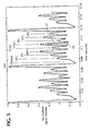
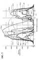
- the repeated sequence of signal pulses emitted from the detector 18 can be seen from Fig. 5 as a typical example. These signal pulses are passed to an analog/digital converter 25, from where signals are passed to the microprocessor 11. As shown in Fig. 5, the reference filter 10 1 will provide a distinct reference pulse designated "Ref" on Fig. 5. The opaque filter material 10 2 will produce the signal valley which is indicated by the reference Opaque. The signal spectrum thus contains a reference signal peak caused by the area-limited, unfiltered light, and the reference signal trough that is due to a blocking of the light rays. The microprocessor 11 will analyse successively each of the other signal peaks in the sequence of measured values, e.g., the signal peak 27 (Fig. 5) relative to a mean value 28 of two adjacent signal valley.
- the reference filter 10 1 will provide a distinct reference pulse designated "Ref" on Fig. 5.
- the opaque filter material 10 2 will produce the signal valley which is indicated by the reference Opaque.
- the signal spectrum thus contains a reference signal
- a light transmission value for an article On the basis of the measurements taken, it will be possible to compute a light transmission value for an article based on the level value 26 of a respective signal peak minus the said mean value.
- the said values may optionally be determined on the basis of a normalised signal intensity, as can also be seen from Fig. 5.
- Fig. 5 shows, in a test installation, it was possible to carry out a scanning cycle in the course of about 70 milliseconds.
- the microprocessor 11 operates so that on the computation of the light transmission values it collects the sequence of the computed light transmission values from a signal cycle in a vector consisting of n elements, wherein n is equal to the number of filters, and compares this with corresponding measured values for a subsequent signal sequence or scanning sequence.
- the microprocessor 11 is capable of computing the average value of two successive signal sequence values and deriving with the aid of a calibration or identification operation, e.g., PLS (Partial Least Squares) discriminant analysis, a unique characteristic of the material type of which the article is made.
- a calibration or identification operation e.g., PLS (Partial Least Squares) discriminant analysis, a unique characteristic of the material type of which the article is made.
- This calibration and identification operation includes use of a calibration and identification algorithm.
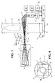
- the filter device may have the appearance of a drum-like structure, e.g., produced using extruded aluminium or plastic.
- the drum 31, in the proposed exemplary embodiment may have a vertical or horizontal rotation shaft, depending upon the design and position of the radiation source 1.
- the drum 31 is supported by arms 32 which are secured to the rotation shaft 34 of the driving motor 33.
- the said filters can be placed in open sections 31' in the wall of the drum. By dividing the drum wall up as shown in Fig. 4, it will be possible to position a total of 16 filters. However, it will be appreciated immediately that it will be possible to position a larger or smaller number of filters on the drum, depending upon the number of filter openings that are provided.
- the drum may be circular in cross-section, or optionally have a polygonal cross-section.
- drum 31 may be positioned on the detector side of the conveyor 17, e.g., rotating about the detector 18 instead of about the radiation source 1.
- the motor 33 which turns the drum 31 may, e.g., be a DC motor like the motor 9 in Fig. 1.
- the filters used in the filter device 6 consist typically of bits of sectors of a circle.
- Pyrex ® glass was found to be suitable as a filter material.
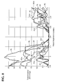
- the spectral transmission of the filter materials multiplied by the transmission of the envelope filter 14 can be seen in more detail in Fig. 7.
- the filter materials shown in this figure must not be perceived as in any way defining the limits of the application of the invention.
- Fig. 8 shows the average transmission curves for each of the types of plastic in question which were identified during the preliminary tests.
- the envelope filter 14 limited the wavelength range to 2.9-3.8 micrometers. However, it will be appreciated that other wavelength ranges may conceivably be employed by using other filters.
- the diaphragm 15, which determines how much radiation is to pass through and be sent towards the article, will also ensure that light rays pass through from only one filter at a time.
- the diaphragm may have a fixed or variable diameter, and an appropriate diameter has been found to be 13 mm, although this must not be perceived as in any way defining the limits of the invention.
- Fig. 2 for the purposes of illustration, it is supposed that the radiation which strikes the article, such as a bottle 20 or 21, is not deflected therein.
- the radiation which strikes the article such as a bottle 20 or 21
- the detector 18 for the purposes of illustration, it is supposed that the radiation which strikes the article, such as a bottle 20 or 21, is not deflected therein.
- light rays will be refracted depending on the angle and where on the bottle they fall.
- some of the light rays which pass through the article will always strike the detector 18, optionally via the mirror 19.
- a simple amplifier with high and low pass filters may be built into or connected to the detector 18.
- the signal from the detector was given a sequence of about 170 Hz and thus periodically had a frequency of 170/10 equalling 17 Hz (because of the 10 filters in the filter device 6).
- 4-5 periods were sampled, whereupon a digital smoothing and normalising was carried out, the signal frequency was computed and the reference point (signal maximum) was localised.
- Fig. 5 shows the signal as it appeared subsequent to this process.
- the transmission values are computed as the level of the respective signal peak, minus the mean value of two "neighbouring troughs".
- the computed values are collected in a vector of 10 elements and are compared with corresponding values for a subsequent signal sequence. If the signal varies excessively, the measurement is rejected, but if the signal is acceptable, average values are computed and then passed on to the calibration and identification algorithms.
- reference numeral 29 indicates peripheral equipment associated with the microprocessor 11, such as equipment for paying a return deposit for articles received, such as returned bottles, and for giving information to a person operating the apparatus if it is a part of a reverse vending machine.
- the reference numeral 30 indicates yet more peripheral equipment, such as after-treatment equipment in the form of, for instance, sorting devices, compactors, material cutters, additional conveyors etc.
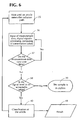
- Block 35 indicates that the system is waiting for an article to enter the radiation path.
- block 36 indicates that measurement data are fed into the detector 18 with subsequent digital signal processing in the A/D converter 25 and with computation of transmission values with the aid of the microprocessor 11.
- the decision block 37 indicates that the microprocessor 11 considers whether the sequence of the received and analysed measured values vary over time. If such is the case, measured values must be fed in and processed again. However, if such is not the case, a new decision will be taken as represented by block 38 with respect to whether the signal level is within an acceptable, predetermined range.
- the article will be classifiable, as indicated at block 40, thus allowing the article to be conveyed to the correct further treatment, whether this be compaction of the article or cutting it up, or to re-use of the article.
- This is generally indicated by reference numeral 41, which also includes the possibility, via the peripheral equipment 29, of printing out a receipt for the person who inserted the article showing the return deposit value, if any, of the article.
- the calibration was done by means of a method which is generally referred to as PLS discriminant analysis, wherein PLS in this connection stands for "Partial Least Squares", and is a method used in the calibration of instruments with many wavelength ranges, and wherein the individual wavelength ranges may be correlated.
- PLS discriminant analysis is well suited for distinguishing between two fractions.
- One of the fractions can be given a y value of +1, whilst the other fraction can be given a y value of -1, and the PLS analysis can then be used to find an optimal regression vector which distinguishes the two fractions under given conditions.
- ten filters are used, as shown in Fig.
- PLS discriminant analysis attempts to plot all articles of one type as the integer 1, whilst all other types are plotted as the integer -1.
- the regression vector used is therefore not quite optimal, even though the method of analysis is simple.
- Use of PLS discriminant analysis is therefore only named as a possible method of analysis.
- Other possible methods of analysis are, e.g., "Principal Component Analysis", direct correlation, Mahalonobis' discrimination, neural network analysis and "fuzzy" logic.
- an article which is to be detected is transported through the detector station in a continuous or discontinuous movement.
- the discontinuous movement may, e.g., mean that the article, when it comes into the path of the light beam 3, is made to stop briefly once or optionally several times with intervening small movements. If an article, e.g., a bottle, is furnished with large labels, it may be expedient to cause the article to rotate in the detector station until a maximum signal intensity through the reference filter, such as the filter 10' in Fig. 3, is registered.
- Fig. 9 shows a modification of the filter disc 7 which can be seen in Fig. 3.
- Fig. 8 shows a modification of the filter disc 7 which can be seen in Fig. 3.
- the filter-carrying disc that does not define the limits of the invention, there is provided a total of eight filters 10, of which the filter 10 1 is a completely transparent reference filter which preferably, but not necessarily, is made of a diaphragmed but material-free (i.e., open) aperture 16 (see Fig. 2).
- the other filters 10 2 , 10 3 , 10 4 , 10 5 , 10 6 , 10 7 and 10 8 could be selected from among, e.g., the following materials: polycarbonate (PC), polystyrene (PS), polyethylene terephthalate (PET), glass (Pyrex ® glass), polyvinyl chloride (PVC), polyethylene (PE), polypropylene (PP) and polyethylene.
- PC polycarbonate
- PS polystyrene
- PET polyethylene terephthalate
- PET glass
- PVC polyvinyl chloride
- PE polyethylene
- PP polypropylene
- each filter 10 1 , 10 2 , 10 3 , 10 4 , 10 5 , 10 6 , 10 7 and 10 8 there are arranged respective filter-free diaphragms, or diaphragms of the same filter material in all, or diaphragms of limited light area, indicated by 42 1 , 42 2 , 42 3 , 42 4 , 42 5 , 42 6 , 42 7 and 42 8 , respectively.
- the diaphragms or apertures 42 will help to produce measured reference values between the measured values of the spectral signatures in the sequence of measured values obtained when light rays successively pass through the filters 10. This will make the determination of such successive measured values more exact because there are always reference values on each side of the signature measured value.
- the signal obtained via the filter 10 1 will produce a start reference (greater amplitude than that obtained via the apertures 42 1 , 42 2 , 42 3 , 42 4 , 42 5 , 42 6 , 42 7 and 42 8 ), whilst the diaphragms or apertures 42 will produce subsequent position indication for the subsequent signature measured values and also indicate the rate of rotation of the disc 7' (number of pulses from the diaphragms/apertures 42 per unit of time).
Landscapes
- Physics & Mathematics (AREA)
- General Health & Medical Sciences (AREA)
- Spectroscopy & Molecular Physics (AREA)
- Health & Medical Sciences (AREA)
- General Physics & Mathematics (AREA)
- Analytical Chemistry (AREA)
- Biochemistry (AREA)
- Chemical & Material Sciences (AREA)
- Life Sciences & Earth Sciences (AREA)
- Immunology (AREA)
- Pathology (AREA)
- Toxicology (AREA)
- Investigating Or Analysing Materials By Optical Means (AREA)
- Analysing Materials By The Use Of Radiation (AREA)
- Crystals, And After-Treatments Of Crystals (AREA)
- Sorting Of Articles (AREA)
- Investigating Materials By The Use Of Optical Means Adapted For Particular Applications (AREA)
Applications Claiming Priority (3)
| Application Number | Priority Date | Filing Date | Title |
|---|---|---|---|
| NO980545 | 1998-02-09 | ||
| NO19980545A NO317826B1 (no) | 1998-02-09 | 1998-02-09 | Fremgangsmate og anordning for gjenkjenning av en materialtype i et objekt, samt anvendelse derav |
| PCT/NO1999/000039 WO1999040414A1 (en) | 1998-02-09 | 1999-02-08 | Method and device for identification of a type of material in an object and utilization therefor |
Publications (2)
| Publication Number | Publication Date |
|---|---|
| EP1055115A1 EP1055115A1 (en) | 2000-11-29 |
| EP1055115B1 true EP1055115B1 (en) | 2008-02-06 |
Family
ID=19901653
Family Applications (1)
| Application Number | Title | Priority Date | Filing Date |
|---|---|---|---|
| EP99909425A Expired - Lifetime EP1055115B1 (en) | 1998-02-09 | 1999-02-08 | Method and device for identification of a type of material in an object and utilization therefor |
Country Status (10)
| Country | Link |
|---|---|
| EP (1) | EP1055115B1 (enExample) |
| JP (1) | JP4291951B2 (enExample) |
| AT (1) | ATE385567T1 (enExample) |
| AU (1) | AU2862799A (enExample) |
| BR (1) | BR9907706A (enExample) |
| CA (1) | CA2319315C (enExample) |
| DE (1) | DE69938099T2 (enExample) |
| ES (1) | ES2303373T3 (enExample) |
| NO (1) | NO317826B1 (enExample) |
| WO (1) | WO1999040414A1 (enExample) |
Cited By (2)
| Publication number | Priority date | Publication date | Assignee | Title |
|---|---|---|---|---|
| EP3935368A1 (en) * | 2019-03-05 | 2022-01-12 | Sacmi Cooperativa Meccanici Imola Societa' Cooperativa | Apparatus and method for inspecting an object |
| EP4153979A1 (en) * | 2020-05-21 | 2023-03-29 | Sacmi Cooperativa Meccanici Imola Societa' Cooperativa | Method and device for inspecting an object |
Families Citing this family (4)
| Publication number | Priority date | Publication date | Assignee | Title |
|---|---|---|---|---|
| DE102007030384B4 (de) * | 2007-06-29 | 2009-02-05 | Dade Behring Marburg Gmbh | Verfahren zur Identifizierung eines transparenten Objekts anhand seines Absorptionsspektrums |
| DE102010007365B4 (de) | 2010-02-10 | 2012-03-22 | Envipco Holding N.V. | Vorrichtung zum Erfassen und Detektieren von Objekten |
| IT201900006738A1 (it) * | 2019-05-10 | 2020-11-10 | Inpeco Holding Ltd | Dispositivo e procedimento per screening di un campione biologico |
| EP3912737B1 (en) | 2020-05-22 | 2023-12-27 | Inndeo Proyectos Industriales, S.L. | System and method for sorting packaged products |
Citations (1)
| Publication number | Priority date | Publication date | Assignee | Title |
|---|---|---|---|---|
| US6433338B1 (en) * | 1998-02-09 | 2002-08-13 | Tomra Systems Asa | Method and device for identification of a type of material in an object and utilization therefor |
Family Cites Families (3)
| Publication number | Priority date | Publication date | Assignee | Title |
|---|---|---|---|---|
| DE4340795A1 (de) * | 1993-08-24 | 1995-03-02 | Hartmut Dr Rer Nat Lucht | Verfahren und Anordnung zur Messung und Trennung von Körpern in Bezug auf ihre Materialzusammensetzung |
| DE19543134A1 (de) * | 1995-11-18 | 1997-05-22 | Dietrich Dr Wienke | Verfahren und Vorrichtung zur getrennten Erfassung von Wertstoffen - insbesondere von Kunststoffverpackungen - in Form dezentral aufstellbarer sensorbetriebener intelligenter Container |
| DE19601923C1 (de) * | 1996-01-12 | 1997-07-24 | Inst Chemo Biosensorik | Verfahren und Vorrichtung zum Erkennen organischer Substanzen |
-
1998
- 1998-02-09 NO NO19980545A patent/NO317826B1/no not_active IP Right Cessation
-
1999
- 1999-02-08 BR BR9907706-0A patent/BR9907706A/pt not_active Application Discontinuation
- 1999-02-08 WO PCT/NO1999/000039 patent/WO1999040414A1/en not_active Ceased
- 1999-02-08 DE DE69938099T patent/DE69938099T2/de not_active Expired - Lifetime
- 1999-02-08 ES ES99909425T patent/ES2303373T3/es not_active Expired - Lifetime
- 1999-02-08 AT AT99909425T patent/ATE385567T1/de active
- 1999-02-08 EP EP99909425A patent/EP1055115B1/en not_active Expired - Lifetime
- 1999-02-08 AU AU28627/99A patent/AU2862799A/en not_active Abandoned
- 1999-02-08 CA CA2319315A patent/CA2319315C/en not_active Expired - Lifetime
- 1999-02-08 JP JP2000530777A patent/JP4291951B2/ja not_active Expired - Lifetime
Patent Citations (1)
| Publication number | Priority date | Publication date | Assignee | Title |
|---|---|---|---|---|
| US6433338B1 (en) * | 1998-02-09 | 2002-08-13 | Tomra Systems Asa | Method and device for identification of a type of material in an object and utilization therefor |
Non-Patent Citations (1)
| Title |
|---|
| VAN DEN BROEK W.H.A.M. ET AL: "Identification of Plastics among Nonplastics in Mixed Waste by Remote Sensing Near-Infrared Imaging Spectroscopy. 1. Image Improvement and Analysis by Singular Value Decomposition", ANAL. CHEM., vol. 67, no. 20, 15 October 1995 (1995-10-15), WASHINGTON, DC, US, pages 3753 - 3759, XP000541459 * |
Cited By (3)
| Publication number | Priority date | Publication date | Assignee | Title |
|---|---|---|---|---|
| EP3935368A1 (en) * | 2019-03-05 | 2022-01-12 | Sacmi Cooperativa Meccanici Imola Societa' Cooperativa | Apparatus and method for inspecting an object |
| US12111269B2 (en) | 2019-03-05 | 2024-10-08 | Sacmi Cooperative Meccanici Imola Societa' Cooperativa | Apparatus and method for inspecting an object |
| EP4153979A1 (en) * | 2020-05-21 | 2023-03-29 | Sacmi Cooperativa Meccanici Imola Societa' Cooperativa | Method and device for inspecting an object |
Also Published As
| Publication number | Publication date |
|---|---|
| AU2862799A (en) | 1999-08-23 |
| NO980545D0 (no) | 1998-02-09 |
| EP1055115A1 (en) | 2000-11-29 |
| CA2319315A1 (en) | 1999-08-12 |
| JP2002502966A (ja) | 2002-01-29 |
| NO980545L (no) | 1999-08-10 |
| BR9907706A (pt) | 2001-09-04 |
| DE69938099D1 (de) | 2008-03-20 |
| JP4291951B2 (ja) | 2009-07-08 |
| CA2319315C (en) | 2012-01-17 |
| WO1999040414A1 (en) | 1999-08-12 |
| ES2303373T3 (es) | 2008-08-01 |
| ATE385567T1 (de) | 2008-02-15 |
| NO317826B1 (no) | 2004-12-13 |
| DE69938099T2 (de) | 2009-01-29 |
Similar Documents
| Publication | Publication Date | Title |
|---|---|---|
| US6433338B1 (en) | Method and device for identification of a type of material in an object and utilization therefor | |
| US6313423B1 (en) | Application of Raman spectroscopy to identification and sorting of post-consumer plastics for recycling | |
| US6509537B1 (en) | Method and device for detecting and differentiating between contaminations and accepts as well as between different colors in solid particles | |
| US3747755A (en) | Apparatus for determining diffuse and specular reflections of infrared radiation from a sample to classify that sample | |
| US7564943B2 (en) | Method and apparatus for sorting materials according to relative composition | |
| US6483581B1 (en) | Raman system for rapid sample indentification | |
| Serranti et al. | Hyperspectral imaging for process and quality control in recycling plants of polyolefin flakes | |
| US9116100B2 (en) | Method for the identification of materials in a container | |
| US4915827A (en) | Method and apparatus for optical sorting of materials using near infrared absorbtion criteria | |
| JP2005535895A5 (enExample) | ||
| CN104849231A (zh) | 一种塑料材质在线识别的方法及装置 | |
| CN106872393A (zh) | 一种塑料废弃物中目标材质识别方法及装置 | |
| EP1055115B1 (en) | Method and device for identification of a type of material in an object and utilization therefor | |
| Van Den Broek et al. | Plastic identification by remote sensing spectroscopic NIR imaging using kernel partial least squares (KPLS) | |
| Feldhoff et al. | On-line post consumer package identification by NIR spectroscopy combined with a FuzzyARTMAP classifier in an industrial environment | |
| Bonifazi et al. | Recycling-oriented characterization of the PET waste stream by SWIR hyperspectral imaging and variable selection methods | |
| JPH11508689A (ja) | 手持ち赤外分光器を用いてリサイクル可能なカーペットを同定する方法 | |
| Broek et al. | Application of a spectroscopic infrared focal plane array sensor for on-line identification of plastic waste | |
| JP2011226821A (ja) | 識別装置および識別方法 | |
| JP2002214136A (ja) | プラスチック材の材質判別方法及び装置 | |
| Feldhoff et al. | Fast identification of packaging waste by near infrared spectroscopy with an InGaAs array spectrograph combined with neural networks | |
| Serranti et al. | Hyperspectral-imaging-based techniques applied to wheat kernels characterization | |
| JP2011214917A (ja) | ラマン散乱に基づく識別方法および識別装置、並びにラマン散乱スペクトルの計測方法および計測装置 | |
| De Biasio et al. | Detecting and discriminating PE and PP polymers for plastics recycling using NIR imaging spectroscopy | |
| JPH06288913A (ja) | 瓶類分別検査方法 |
Legal Events
| Date | Code | Title | Description |
|---|---|---|---|
| PUAI | Public reference made under article 153(3) epc to a published international application that has entered the european phase |
Free format text: ORIGINAL CODE: 0009012 |
|
| 17P | Request for examination filed |
Effective date: 20000719 |
|
| AK | Designated contracting states |
Kind code of ref document: A1 Designated state(s): AT BE CH CY DE DK ES FI FR GB GR IE IT LI LU MC NL PT SE |
|
| 17Q | First examination report despatched |
Effective date: 20060718 |
|
| GRAP | Despatch of communication of intention to grant a patent |
Free format text: ORIGINAL CODE: EPIDOSNIGR1 |
|
| GRAS | Grant fee paid |
Free format text: ORIGINAL CODE: EPIDOSNIGR3 |
|
| GRAA | (expected) grant |
Free format text: ORIGINAL CODE: 0009210 |
|
| AK | Designated contracting states |
Kind code of ref document: B1 Designated state(s): AT BE CH CY DE DK ES FI FR GB GR IE IT LI LU MC NL PT SE |
|
| REG | Reference to a national code |
Ref country code: GB Ref legal event code: FG4D |
|
| REG | Reference to a national code |
Ref country code: CH Ref legal event code: EP |
|
| REG | Reference to a national code |
Ref country code: IE Ref legal event code: FG4D |
|
| REF | Corresponds to: |
Ref document number: 69938099 Country of ref document: DE Date of ref document: 20080320 Kind code of ref document: P |
|
| REG | Reference to a national code |
Ref country code: SE Ref legal event code: TRGR |
|
| PG25 | Lapsed in a contracting state [announced via postgrant information from national office to epo] |
Ref country code: FI Free format text: LAPSE BECAUSE OF FAILURE TO SUBMIT A TRANSLATION OF THE DESCRIPTION OR TO PAY THE FEE WITHIN THE PRESCRIBED TIME-LIMIT Effective date: 20080206 |
|
| REG | Reference to a national code |
Ref country code: ES Ref legal event code: FG2A Ref document number: 2303373 Country of ref document: ES Kind code of ref document: T3 |
|
| PG25 | Lapsed in a contracting state [announced via postgrant information from national office to epo] |
Ref country code: BE Free format text: LAPSE BECAUSE OF FAILURE TO SUBMIT A TRANSLATION OF THE DESCRIPTION OR TO PAY THE FEE WITHIN THE PRESCRIBED TIME-LIMIT Effective date: 20080206 |
|
| REG | Reference to a national code |
Ref country code: CH Ref legal event code: PL |
|
| ET | Fr: translation filed | ||
| PG25 | Lapsed in a contracting state [announced via postgrant information from national office to epo] |
Ref country code: PT Free format text: LAPSE BECAUSE OF FAILURE TO SUBMIT A TRANSLATION OF THE DESCRIPTION OR TO PAY THE FEE WITHIN THE PRESCRIBED TIME-LIMIT Effective date: 20080707 Ref country code: MC Free format text: LAPSE BECAUSE OF NON-PAYMENT OF DUE FEES Effective date: 20080228 Ref country code: LI Free format text: LAPSE BECAUSE OF NON-PAYMENT OF DUE FEES Effective date: 20080229 Ref country code: DK Free format text: LAPSE BECAUSE OF FAILURE TO SUBMIT A TRANSLATION OF THE DESCRIPTION OR TO PAY THE FEE WITHIN THE PRESCRIBED TIME-LIMIT Effective date: 20080206 Ref country code: CH Free format text: LAPSE BECAUSE OF NON-PAYMENT OF DUE FEES Effective date: 20080229 |
|
| PLBE | No opposition filed within time limit |
Free format text: ORIGINAL CODE: 0009261 |
|
| STAA | Information on the status of an ep patent application or granted ep patent |
Free format text: STATUS: NO OPPOSITION FILED WITHIN TIME LIMIT |
|
| 26N | No opposition filed |
Effective date: 20081107 |
|
| PG25 | Lapsed in a contracting state [announced via postgrant information from national office to epo] |
Ref country code: IE Free format text: LAPSE BECAUSE OF NON-PAYMENT OF DUE FEES Effective date: 20080208 |
|
| PG25 | Lapsed in a contracting state [announced via postgrant information from national office to epo] |
Ref country code: CY Free format text: LAPSE BECAUSE OF FAILURE TO SUBMIT A TRANSLATION OF THE DESCRIPTION OR TO PAY THE FEE WITHIN THE PRESCRIBED TIME-LIMIT Effective date: 20080206 |
|
| PG25 | Lapsed in a contracting state [announced via postgrant information from national office to epo] |
Ref country code: IT Free format text: LAPSE BECAUSE OF FAILURE TO SUBMIT A TRANSLATION OF THE DESCRIPTION OR TO PAY THE FEE WITHIN THE PRESCRIBED TIME-LIMIT Effective date: 20080206 |
|
| PG25 | Lapsed in a contracting state [announced via postgrant information from national office to epo] |
Ref country code: LU Free format text: LAPSE BECAUSE OF NON-PAYMENT OF DUE FEES Effective date: 20080208 |
|
| PG25 | Lapsed in a contracting state [announced via postgrant information from national office to epo] |
Ref country code: GR Free format text: LAPSE BECAUSE OF FAILURE TO SUBMIT A TRANSLATION OF THE DESCRIPTION OR TO PAY THE FEE WITHIN THE PRESCRIBED TIME-LIMIT Effective date: 20080507 |
|
| REG | Reference to a national code |
Ref country code: FR Ref legal event code: PLFP Year of fee payment: 18 |
|
| REG | Reference to a national code |
Ref country code: FR Ref legal event code: PLFP Year of fee payment: 19 |
|
| REG | Reference to a national code |
Ref country code: FR Ref legal event code: PLFP Year of fee payment: 20 |
|
| PGFP | Annual fee paid to national office [announced via postgrant information from national office to epo] |
Ref country code: NL Payment date: 20180215 Year of fee payment: 20 |
|
| PGFP | Annual fee paid to national office [announced via postgrant information from national office to epo] |
Ref country code: GB Payment date: 20180215 Year of fee payment: 20 Ref country code: ES Payment date: 20180301 Year of fee payment: 20 Ref country code: DE Payment date: 20180216 Year of fee payment: 20 |
|
| PGFP | Annual fee paid to national office [announced via postgrant information from national office to epo] |
Ref country code: AT Payment date: 20180221 Year of fee payment: 20 Ref country code: FR Payment date: 20180226 Year of fee payment: 20 Ref country code: SE Payment date: 20180206 Year of fee payment: 20 |
|
| REG | Reference to a national code |
Ref country code: DE Ref legal event code: R071 Ref document number: 69938099 Country of ref document: DE |
|
| REG | Reference to a national code |
Ref country code: NL Ref legal event code: MK Effective date: 20190207 |
|
| REG | Reference to a national code |
Ref country code: GB Ref legal event code: PE20 Expiry date: 20190207 |
|
| REG | Reference to a national code |
Ref country code: AT Ref legal event code: MK07 Ref document number: 385567 Country of ref document: AT Kind code of ref document: T Effective date: 20190208 |
|
| REG | Reference to a national code |
Ref country code: SE Ref legal event code: EUG |
|
| PG25 | Lapsed in a contracting state [announced via postgrant information from national office to epo] |
Ref country code: GB Free format text: LAPSE BECAUSE OF EXPIRATION OF PROTECTION Effective date: 20190207 |
|
| REG | Reference to a national code |
Ref country code: ES Ref legal event code: FD2A Effective date: 20200805 |
|
| PG25 | Lapsed in a contracting state [announced via postgrant information from national office to epo] |
Ref country code: ES Free format text: LAPSE BECAUSE OF EXPIRATION OF PROTECTION Effective date: 20190209 |