EP1054476B1 - Elektrischer Verbinder mit Kontaktrückhaltemitteln - Google Patents
Elektrischer Verbinder mit Kontaktrückhaltemitteln Download PDFInfo
- Publication number
- EP1054476B1 EP1054476B1 EP20000110038 EP00110038A EP1054476B1 EP 1054476 B1 EP1054476 B1 EP 1054476B1 EP 20000110038 EP20000110038 EP 20000110038 EP 00110038 A EP00110038 A EP 00110038A EP 1054476 B1 EP1054476 B1 EP 1054476B1
- Authority
- EP
- European Patent Office
- Prior art keywords
- terminal
- connector
- passageway
- primary
- terminal block
- Prior art date
- Legal status (The legal status is an assumption and is not a legal conclusion. Google has not performed a legal analysis and makes no representation as to the accuracy of the status listed.)
- Expired - Lifetime
Links
Images


Classifications
-
- H—ELECTRICITY
- H01—ELECTRIC ELEMENTS
- H01R—ELECTRICALLY-CONDUCTIVE CONNECTIONS; STRUCTURAL ASSOCIATIONS OF A PLURALITY OF MUTUALLY-INSULATED ELECTRICAL CONNECTING ELEMENTS; COUPLING DEVICES; CURRENT COLLECTORS
- H01R13/00—Details of coupling devices of the kinds covered by groups H01R12/70 or H01R24/00 - H01R33/00
- H01R13/40—Securing contact members in or to a base or case; Insulating of contact members
- H01R13/42—Securing in a demountable manner
- H01R13/426—Securing by a separate resilient retaining piece supported by base or case, e.g. collar or metal contact-retention clip
Definitions
- This invention relates to terminal retention in connectors and particularly primary terminal retention.
- a primary terminal retention feature that retains the individual terminals in their respective terminal passageways.
- Connectors typically hold a plurality of terminals, this primary retention feature enables each terminal to be held in place once loaded into the connector while the other terminals are being loaded in their respective passageways.
- a secondary locking member as part of the connector assembly.
- a common form of a secondary locking member involves a structure having a shoulder that is moveable into the passageway in order to provide an obstruction therealong would interfere with a complementary shoulder on the contact and thereby prevent withdraw.
- EP 0 510 583 An example of an electrical connector of this type is illustrated in EP 0 510 583 where a generally rectangular terminal block has a number of electrical terminal receiving cavities with primary connection means disposed along the longer sides of the terminal block and corresponding to each of the respective cavities in order 'to retain the electrical terminals therein.
- the primary connecting means are integrally moulded resilient arms having a latching tab thereupon to engage the contact when it is inserted.
- a secondary locking structure is provided by a flexible hinged flap having a plurality of comb-like teeth thereupon which extend through holes in the terminal block and into the passageway to obstruct the passageways, thereby preventing the terminal from being removed from the terminal block.
- WO 98/31076 A2 Another electrical connector with primary retention means, which is considered as the closest prior art, is known from WO 98/31076 A2.
- a connector for receiving terminals therein that includes a terminal block having outer side walls and opposing end walls, wherein terminal receiving passageways extend between the opposing end walls for receiving a terminal, and a primary retention member is disposed along at least one of the terminal receiving passageways that includes a resilient retention arm that extends into the passageway to retain the terminal therein.
- the primary retention member is made of metal sheet by stamping and bending and is fixed in the housing by press-fitting into attachment slots.
- a connector for receiving terminals therein comprising a terminal block having outer walls and opposing ends walls, a terminal receiving passageway extending between the opposing end walls for receiving a terminal therein, and a primary retention member disposed along the passageway having a resilient retention arm extending into the passageway to retain their terminal therein, the connector being characterised in that the primary retention member is formed from a generally flat plate and includes a body set in the terminal block and the retention arm extends from the body into the passageway.
- a connector for receiving terminal therein comprising a terminal block having outer side walls that intersect to define corners and opposing end walls, a terminal receiving passageway extending between the opposing end walls for receiving a terminal therein, and a primary retention member disposed along at least one of the terminal receiving passageways and having resilient retention arm extending into the passageway to retain the terminal therein, where the at least one passageway is located in the vicinity of one of the corners, the connector is characterised in that primary retention member is disposed between the one of the corners and the one passageway in the vicinity of the corner.
- a connector for receiving terminals therein comprising a terminal block having outer side walls and opposing end walls with terminal receiving passageways extending therethrough, primary retention members are disposed along respective passageways and include a moulded resilient latch arm formed integrally with terminal block that extends into the passageway to prevent withdraw of the inserted terminal, the connector characterised in that the terminal block includes a post located behind the resilient latch arm to prevent overstress.
- an. effective primary retention of terminals in a terminal block may be achieved even when the walls adjacent the terminal receiving passageways are relatively close thereto.
- the primary retention member may be stamped and formed from a thin sheet of metal. It is another advantage of the invention that by providing a primary retention member in the vicinity of the corner, additional material of the terminal block is available in order to establish the primary retention. It is another advantage of the invention that by providing a post behind a resilient latch arm of the primary retention member to prevent overstress, smaller latch arms may be used.
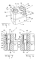
- the connector 2 includes a terminal block 4 having outer walls 6, 7, 8, 9, 10 and opposing end walls 12, 14.
- a pair of terminal receiving passageways 16 extend through the terminal block 4 between the opposing end walls 12, 14.
- terminals 18 are meant to be generic in nature and could represent either fibre optic or electrical terminals.
- Respective primary retention members 20, 22 are disposed along the passageways for retaining the terminals 18 therein.
- a secondary locking member 24 is received within a slot 26 that extends transversely across the terminal block 4 relative to the passageways 16.
- side walls 6 and 10 define a corner 28 and side walls 8 and 9 define a corner 30.
- the primary retention member 20 is a stamped and formed piece of flat metal having a body portion 32.
- a locking lance 34 is sheared out of the body 32 in order to retain the retention member 20 within terminal block 4.
- a resilient retention arm 36 is also sheared from the body 32 and folded so that a free end 38 extends into passageway 16.
- the resilient retention arm 36 is constructed such that as the terminal 18 is inserted into the housing, the retention arm 36 will deflect and a shoulder 40 of the terminal 18 passes by and then resile therebehind to prevent removal of the terminal 18.
- the primary retention member 20 is disposed within a channel 43 that is moulded into the terminal block 4.
- the primary retention member 20 is disposed' between the passageway 16 and the corner 30 defined by side walls 9 and 8.
- the primary retention member 20 is relatively thin and takes up a minimum amount of space, thereby making a particularly useful in connectors having relatively thin side portions between the terminal passageways 16 and an adjacent side 9.
- the body 32 and the associated retention arm 36 could be curved to more closely comply with the shape of the passageway 16 when cylindrical terminal 18 are used.
- non-cylindrical passageways may be formed and the primary retention member may be disposed along the sidewall.
- the primary retention member 22 is a conventionally configured and integrally moulded member with the terminal block 4.
- Primary retention member 22 includes a resilient arm 42 suspended in cantilevered fashion and extending generally from opposing end wall 12 towards a free end 44.
- a latch 46 is formed at the free end 44 and extends into the passageway 16.
- the latch 46 is configured to allow a shoulder 40 of the terminal 18 to pass during insertion and then when the latch arm 42 resiles back to prevent withdraw of the terminal. This is best seen in figure 4.
- a notch 48 opposite the latch 46.
- a post 50 that prevents overstress of the primary retention member 22.
- the retention member 22 is formed between the terminal receiving passageway 16 and the corner 28 defined by outer side walls 6 and 10. As can bee seen, in the vicinity of the resilient arm 42, a portion of the terminal block 4 at the corner 28 has been removed. This enables the post 50 to be easily formed behind the resilient arm 42. However, a primary retention member 22 such as described above and the overstressed post 50 may be incorporated anywhere along the housing where it is desired to prevent damage to the primary retention member 22 by way of overstressing. This is especially applicable where the side walls are relatively close to the terminal receiving passageway 16.
- FIGS. 3 and 4 sectional views are shown that illustrate how the primary retention members 20, 22 interact with the terminals 18 when they are received within passageways 16.
- retention arm 36 of the body 32 extends into the passageway 16 to fit behind the shoulder 40.
- Locking lance 34 is further received within a cavity 52 to prevent removal of the retention member 20.
- resilient arm 44 is shown cantilevered downward from the end wall 12 to a free end 44 which fits behind the shoulder of the terminal 18.
- Overstress post 50 is shown behind the free end 44 such that excessive outward deflection of the resilient arm 42 will be prevented by way of the post 50 which is located behind the free end 44.
- the secondary locking member 24 that is inserted into the slot 26 includes a pair of arms 54 defining a U-shaped structure such that the arms 54 fit on either side of the terminal behind a second shoulder 56 thereof.
- the second embodiment 200 also includes a terminal block 204 and primary terminal retaining members 220, 222.
- the second embodiment is generally identical to the first embodiment with the exception of a different secondary locking member 224.
- the secondary locking member 224 is a key-like member integrally moulded to the terminal block 204 by way of a frangible portion 260.
- the secondary locking member 224 is to be received within a cavity 226 that is located between terminal receiving passageways 16 such that shoulders 262 will co-operate with the shoulders 56 (not shown in figure 5).
- the secondary locking member 224 As a result of rotating the secondary locking member 224 in the direction of arrow A, the secondary locking member 224 is inserted into the cavity 226 free end 268 first. The act of rotation in the direction of arrow A brakes the frangible portion 260 and enables the secondary locking member 224 to be properly seated within the terminal block 204.
- primary retention has been provided for a connector having relatively thin sections between terminal receiving passageways and outer side walls of a terminal block. This is accomplished by either locating the primary terminal retention members at the corners defined by the side walls that are in the vicinity of the terminal receiving passageways, or by providing a primary retention member that is stamped and formed from thin sheets of material and received within the terminal block or by enhancing the structural integrity of a primary locking member by providing overstress protection thereto.
Landscapes
- Connector Housings Or Holding Contact Members (AREA)
Claims (7)
- Verbinder (2) für das Aufnehmen von Anschlußklemmen (18) darin, wobei der Verbinder aufweist: einen Klemmenblock (4) mit äußeren Seitenwänden (6-10), die sich schneiden, um Ecken (28, 30) zu definieren, und gegenüberliegenden Stirnseitenwänden (12, 14); mindestens einen Klemmenaufnahmedurchgang (16), der sich zwischen den gegenüberliegenden Stirnseitenwänden für das Aufnehmen einer Anschlußklemme darin erstreckt; und ein primäres Arretierelement (20, 22), angeordnet längs eines Klemmenaufnahmedurchganges und mit einem elastischen Arretierarm (36, 42), der sich in den Durchgang hinein erstreckt, um die Anschlußklemme darin zu halten, wobei ein Durchgang in der Nähe der einen der Ecken angeordnet ist, wobei der Verbinder dadurch gekennzeichnet ist, daß das primäre Arretierelement zwischen einer der Ecken und dem Durchgang in der Nähe der Ecke angeordnet ist.
- Verbinder nach Anspruch 1, bei dem das primäre Arretierelement (20) ein gestanztes und geformtes Metallelement ist.
- Verbinder nach Anspruch 1, bei dem das primäre Arretierelement (22) zusammenhängend mit dem Klemmenblock geformt ist.
- Verbinder nach Anspruch 3, bei dem sich der elastische Arretierarm (42) zu einem freien Ende (44) erstreckt und der Klemmenblock eine Stütze (50) hinter dem freien Ende umfaßt, um eine Überbeanspruchung des Armes zu verhindern.
- Verbinder nach Anspruch 4, bei dem der elastische Arretierarm (42) einen Einschnitt (48) umfaßt, der der Stütze entspricht.
- Verbinder nach Anspruch 2, dadurch gekennzeichnet, daß das primäre Arretierelement (20) aus einer im allgemeinen flachen Platte gebildet wird und einen Körper (32) umfaßt, der in den Klemmenblock eingesetzt wird, und daß sich der Arretierarm vom Körper in den Durchgang erstreckt.
- Verbinder nach Anspruch 6, dadurch gekennzeichnet, daß das primäre Arretierelement in einem Kanal (43) des Klemmenblockes aufgenommen wird, der längs des Durchganges angeordnet ist.
Priority Applications (1)
| Application Number | Priority Date | Filing Date | Title |
|---|---|---|---|
| EP20000110038 EP1054476B1 (de) | 1999-05-12 | 2000-05-12 | Elektrischer Verbinder mit Kontaktrückhaltemitteln |
Applications Claiming Priority (3)
| Application Number | Priority Date | Filing Date | Title |
|---|---|---|---|
| EP99109544 | 1999-05-12 | ||
| EP99109544 | 1999-05-12 | ||
| EP20000110038 EP1054476B1 (de) | 1999-05-12 | 2000-05-12 | Elektrischer Verbinder mit Kontaktrückhaltemitteln |
Publications (2)
| Publication Number | Publication Date |
|---|---|
| EP1054476A1 EP1054476A1 (de) | 2000-11-22 |
| EP1054476B1 true EP1054476B1 (de) | 2004-01-28 |
Family
ID=26070924
Family Applications (1)
| Application Number | Title | Priority Date | Filing Date |
|---|---|---|---|
| EP20000110038 Expired - Lifetime EP1054476B1 (de) | 1999-05-12 | 2000-05-12 | Elektrischer Verbinder mit Kontaktrückhaltemitteln |
Country Status (1)
| Country | Link |
|---|---|
| EP (1) | EP1054476B1 (de) |
Family Cites Families (3)
| Publication number | Priority date | Publication date | Assignee | Title |
|---|---|---|---|---|
| BR9404858A (pt) * | 1993-12-07 | 1995-08-08 | Whitaker Corp | Conector elétrico |
| JP3216803B2 (ja) * | 1997-01-08 | 2001-10-09 | タイコエレクトロニクスアンプ株式会社 | コンタクト保持部材及びそれを使用する電気コネクタ |
| EP0961357A3 (de) * | 1998-05-29 | 2002-06-12 | The Whitaker Corporation | Elektrischer Verbinder mit einem Kontaktverriegelungselement |
-
2000
- 2000-05-12 EP EP20000110038 patent/EP1054476B1/de not_active Expired - Lifetime
Also Published As
| Publication number | Publication date |
|---|---|
| EP1054476A1 (de) | 2000-11-22 |
Similar Documents
| Publication | Publication Date | Title |
|---|---|---|
| EP1623487B1 (de) | Modulare buchsenanordnung für buchsenstecker mit variierender anzahl von leitungen | |
| US5564952A (en) | Electrical plug connector with blade receiving slots | |
| EP0470471A2 (de) | Paneel-Befestigungsbügel | |
| US5004434A (en) | Printed circuit board edge connector | |
| JP3120378B2 (ja) | シャッター付きの電気コネクタ | |
| US5470258A (en) | Electrical connector | |
| US6368148B1 (en) | Ribbon cable connector with ground bus | |
| EP0568273B1 (de) | Modularer Stecker mit verbesserter Kabelzugentlastung | |
| EP0321285B1 (de) | Zweidirektionale, isolationsverdrängende, elektrische Kontaktklemme | |
| EP0388048A2 (de) | Elektrischer Verbinder | |
| US5711067A (en) | Method of forming electrical connector | |
| KR960016876B1 (ko) | 과도 응력 방지 수단을 갖는 수 전기 단자 | |
| EP1091450B1 (de) | Verbinder | |
| EP0963009B1 (de) | Eine Vorrichtung zur Verhinderung einer fehlerhaften Zusammensetzung eines Verbindergehäuses mit einem Deckel und einen Verbinder mit einer solchen Vorrichtung | |
| EP0775374B1 (de) | Steckverbinder für ein elektrisches kabel | |
| EP0657965B1 (de) | Elektrischer Verbinder mit verbesserten Kontaktrückhaltemitteln | |
| WO1996027221A1 (en) | Electrical connector with terminal supporting walls | |
| EP0748001A1 (de) | Anschlusselement für Verbinder mit Kurzschlussbrücke und Verbindergehäuse | |
| US6589080B2 (en) | Terminal fitting and a connector | |
| US6554645B1 (en) | Primary terminal retention feature for connectors | |
| EP1054476B1 (de) | Elektrischer Verbinder mit Kontaktrückhaltemitteln | |
| US4992063A (en) | Electrical connector | |
| US6042428A (en) | Connector insert retention | |
| EP1261070B1 (de) | Anschlussteil und Steckverbinder mit einem solchen Anschlussteil | |
| EP1073155B1 (de) | Verbinder mit primären und sekundären Verriegelungsvorrichtungen |
Legal Events
| Date | Code | Title | Description |
|---|---|---|---|
| PUAI | Public reference made under article 153(3) epc to a published international application that has entered the european phase |
Free format text: ORIGINAL CODE: 0009012 |
|
| AK | Designated contracting states |
Kind code of ref document: A1 Designated state(s): DE FR GB |
|
| AX | Request for extension of the european patent |
Free format text: AL;LT;LV;MK;RO;SI |
|
| 17P | Request for examination filed |
Effective date: 20010412 |
|
| AKX | Designation fees paid |
Free format text: DE FR GB |
|
| 17Q | First examination report despatched |
Effective date: 20020628 |
|
| GRAP | Despatch of communication of intention to grant a patent |
Free format text: ORIGINAL CODE: EPIDOSNIGR1 |
|
| GRAS | Grant fee paid |
Free format text: ORIGINAL CODE: EPIDOSNIGR3 |
|
| GRAA | (expected) grant |
Free format text: ORIGINAL CODE: 0009210 |
|
| AK | Designated contracting states |
Kind code of ref document: B1 Designated state(s): DE FR GB |
|
| REG | Reference to a national code |
Ref country code: GB Ref legal event code: FG4D |
|
| REF | Corresponds to: |
Ref document number: 60007916 Country of ref document: DE Date of ref document: 20040304 Kind code of ref document: P |
|
| ET | Fr: translation filed | ||
| PLBE | No opposition filed within time limit |
Free format text: ORIGINAL CODE: 0009261 |
|
| STAA | Information on the status of an ep patent application or granted ep patent |
Free format text: STATUS: NO OPPOSITION FILED WITHIN TIME LIMIT |
|
| 26N | No opposition filed |
Effective date: 20041029 |
|
| REG | Reference to a national code |
Ref country code: FR Ref legal event code: PLFP Year of fee payment: 17 |
|
| REG | Reference to a national code |
Ref country code: FR Ref legal event code: PLFP Year of fee payment: 18 |
|
| REG | Reference to a national code |
Ref country code: FR Ref legal event code: PLFP Year of fee payment: 19 |
|
| PGFP | Annual fee paid to national office [announced via postgrant information from national office to epo] |
Ref country code: FR Payment date: 20180411 Year of fee payment: 19 |
|
| PGFP | Annual fee paid to national office [announced via postgrant information from national office to epo] |
Ref country code: GB Payment date: 20180509 Year of fee payment: 19 |
|
| PGFP | Annual fee paid to national office [announced via postgrant information from national office to epo] |
Ref country code: DE Payment date: 20190430 Year of fee payment: 20 |
|
| GBPC | Gb: european patent ceased through non-payment of renewal fee |
Effective date: 20190512 |
|
| PG25 | Lapsed in a contracting state [announced via postgrant information from national office to epo] |
Ref country code: GB Free format text: LAPSE BECAUSE OF NON-PAYMENT OF DUE FEES Effective date: 20190512 |
|
| REG | Reference to a national code |
Ref country code: DE Ref legal event code: R071 Ref document number: 60007916 Country of ref document: DE |
|
| PG25 | Lapsed in a contracting state [announced via postgrant information from national office to epo] |
Ref country code: FR Free format text: LAPSE BECAUSE OF NON-PAYMENT OF DUE FEES Effective date: 20190531 |