EP1054216A2 - Heat storing fireplace - Google Patents
Heat storing fireplace Download PDFInfo
- Publication number
- EP1054216A2 EP1054216A2 EP00660095A EP00660095A EP1054216A2 EP 1054216 A2 EP1054216 A2 EP 1054216A2 EP 00660095 A EP00660095 A EP 00660095A EP 00660095 A EP00660095 A EP 00660095A EP 1054216 A2 EP1054216 A2 EP 1054216A2
- Authority
- EP
- European Patent Office
- Prior art keywords
- fireplace
- inner part
- supporting structure
- firebox
- grate
- Prior art date
- Legal status (The legal status is an assumption and is not a legal conclusion. Google has not performed a legal analysis and makes no representation as to the accuracy of the status listed.)
- Granted
Links
Images


Classifications
-
- F—MECHANICAL ENGINEERING; LIGHTING; HEATING; WEAPONS; BLASTING
- F24—HEATING; RANGES; VENTILATING
- F24B—DOMESTIC STOVES OR RANGES FOR SOLID FUELS; IMPLEMENTS FOR USE IN CONNECTION WITH STOVES OR RANGES
- F24B1/00—Stoves or ranges
- F24B1/18—Stoves with open fires, e.g. fireplaces
-
- F—MECHANICAL ENGINEERING; LIGHTING; HEATING; WEAPONS; BLASTING
- F24—HEATING; RANGES; VENTILATING
- F24B—DOMESTIC STOVES OR RANGES FOR SOLID FUELS; IMPLEMENTS FOR USE IN CONNECTION WITH STOVES OR RANGES
- F24B1/00—Stoves or ranges
- F24B1/18—Stoves with open fires, e.g. fireplaces
- F24B1/191—Component parts; Accessories
Definitions
- the present invention relates to a heat-storing fireplace as defined in the preamble of claim 1.
- the above-mentioned need for maintenance means that at least some of the structural materials, elements or stones of the firebox need to be replaced with new ones.
- in order to replace a part of the heat storing material of the firebox it is necessary to dismantle the entire inner part of the fireplace from the top down to the parts to be replaced, and in some cases even the shell has to be partially dismantled.
- Elements or stones attached to each other during installation of the fireplace are often damaged during dismantling when being extricated from each other, even if they are flawless and of first-class quality.
- damaged firebox stones are renewed, it is generally necessary to replace many other stones as well, the number of which may be multiple times larger than that of stones originally in need of replacement.
- the object of the invention is to eliminate the problems referred to above.
- a specific object of the invention is to disclose a new type of structure for use in heat-storing fireplaces which will make it possible to carry out maintenance operations on the firebox structures without touching the rest of the inner part of the fireplace.
- a heat-storing fireplace comprises an inner part and a shell surrounding the inner part.
- the shell surrounds the inner part at least on all four sides and above.
- the inner part comprises a grate, a firebox and above the firebox an uptake for passing the combustion gases from the fireplace into a chimney flue.
- the uptake may provide a passage into the chimney flue directly from above the firebox, or the combustion gases may be passed down e.g. via side ducts between the inner part and the shell and only from the lower part of the fireplace into the chimney flue.
- Other uptake structures for passing the combustion gases from the firebox into the chimney flue are also possible.
- the fireplace comprises an inner part with a firebox and a shell separate from the firebox and surrounding it.
- the inner part comprises a supporting structure arranged to bear that portion of the inner part which lies above the supporting structure.
- the basic idea of the invention is that, by using supporting structures of a certain kind in the inner part of the fireplace, certain wall structures of the firebox can be implemented in such a way that they do not bear the weight of any structures of the inner part above them, thus allowing them to be easily dismantled and replaced via a door without breaking up the inner part above them.
- the supporting structure is preferably disposed above that portion of the inner part which is exposed to the greatest heat stress.
- the position of the supporting structure may also be determined in other ways by estimating the need for replacement of the stones of the inner part; for example, the stones in the lower part of the firebox may be exposed to a large mechanical stress if the pieces of fuel wood are thrown in against the walls of the firebox.
- the supporting structure preferably consists of a rigid, partly open or closed frame designed to carry the upper portion of the inner part upon it.
- the supporting structure may also only consist of suitable beams or other supports which can be used to implement the desired function.
- the supporting structure which may be made of steel, cast iron or some other suitable material, consists of a means extending in substantially only one horizontal plane. In this case, it may be mounted on the shell of the fireplace or on separate supports provided between the shell and the inner part.
- the supporting structure preferably comprises supporting legs, so that the supporting structure rests on a structure below the inner part elements intended to be replaceable.
- the actual supporting structure when placed in the area of the upper part of the firebox, it may rest on its supporting legs in the area of the lower part of the firebox, e.g. on the level of the grate.
- the heat-storing fireplace of the invention has significant advantages.
- the supporting structure of the invention makes it possible to dismantle and replace the elements or stones in the firebox walls via the fireplace door without touching the rest of the inner part of the fireplace.
- the structure of the invention reduces the time needed for the replacement of damage stones to a level as low as 10% and the material needed in the replacement operation by as much as 80% as compared with prior art.
- the heat-storing fireplace presented in the drawings which preferably in entirely made of soapstone elements, comprises an inner part 1, which comprises a fire grate 2 and an ash box below it. Above the fire grate there is a firebox 3 defined by a back wall 9 and side walls 10, the firebox opening out via a door in the front wall. The door is not shown in the figure. From the firebox upwards, the inner part 1 forms an uptake 4 which conducts the combustion gases from the firebox into a chimney flue.
- the inner part 1 is surrounded by a soapstone shell 5 covering it on the front side, lateral sides, back side and at the top.
- the uptake 4 bends out to the sides in the upper part of the inner part, forming side ducts extending downward between the inner part and the shell so that the side ducts meet in the lower part of the fireplace, behind the ash box, conducting the combustion gases from there into the chimney flue.
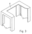
- a rigid rectangular supporting structure 6 placed around the firebox walls, i.e. the side walls 10 and the back wall 9, in a horizontal plane. Extending downward from each of the four corners of the supporting structure are supporting legs 7, which are mounted in the inner part 1 at the level of the grate 2. The entire portion of the inner part 1 situated above the supporting structure 6 is built on and supported by the supporting structure 6 so that its weight is transmitted via the supporting structure 6 and its supporting legs 7 to the grate level and to the portion of the inner part below it, as can be seen from Fig. 2.
- the back wall 9 and side walls 10 of the firebox 3 can be built last after the rest of the inner part, in the space defined by the supporting structure 6 and the supporting legs 7, and similarly they can be separately dismantled and replaced if necessary without touching the rest of the inner part.
- the supporting structure 6 with its supporting legs 7 has been formed from suitable profiled angle iron bar so that, as a whole, it forms in the firebox a boxlike structure in which the elements 8 forming the firebox can be easily set. It is even possible that the elements 8 need not be glued or otherwise attached to each other in any way; instead, they can be left completely loose as the angle iron bars forming the supporting structure 6 and supporting legs 7 provide sufficient sealing of the joints of the elements 8 and their corner areas.
- the portions of the inner part that are exposed to the greatest heat stress or a desired area of the firebox walls defined in some other way can be implemented as a separate structure which does not bear the weight of the portion of the inner part above it.
- this desired area of the firebox walls can be easily dismantled via the fireplace door when necessary and the elements in it can be replaced without touching the rest of the structure of the fireplace.
Landscapes
- Engineering & Computer Science (AREA)
- Chemical & Material Sciences (AREA)
- Combustion & Propulsion (AREA)
- Mechanical Engineering (AREA)
- General Engineering & Computer Science (AREA)
- Baking, Grill, Roasting (AREA)
- Furnace Housings, Linings, Walls, And Ceilings (AREA)
- Inorganic Insulating Materials (AREA)
- Resistance Heating (AREA)
- Crystals, And After-Treatments Of Crystals (AREA)
- Photoreceptors In Electrophotography (AREA)
- Control Of Motors That Do Not Use Commutators (AREA)
Abstract
Description
- The present invention relates to a heat-storing fireplace as defined in the preamble of
claim 1. - In efficient use of a heat-storing fireplace with a clean combustion process, the firebox wall material is exposed to the greatest heat stress. Besides, fuel wood is often placed in the firebox by throwing the pieces of wood against the firebox walls, the wall material being thus exposed to mechanical stresses as well. Therefore, it is natural that, after decades of use, the fireplace will need maintenance as the properties of the firebox material may have changed or the firebox may have been damaged.
- The above-mentioned need for maintenance means that at least some of the structural materials, elements or stones of the firebox need to be replaced with new ones. In present fireplace structures, in order to replace a part of the heat storing material of the firebox, it is necessary to dismantle the entire inner part of the fireplace from the top down to the parts to be replaced, and in some cases even the shell has to be partially dismantled. Elements or stones attached to each other during installation of the fireplace are often damaged during dismantling when being extricated from each other, even if they are flawless and of first-class quality. As a result, when damaged firebox stones are renewed, it is generally necessary to replace many other stones as well, the number of which may be multiple times larger than that of stones originally in need of replacement.
- Thus, in prior art, partial replacement and maintenance of firebox materials is a very slow and difficult and therefore expensive operation. Moreover, the costs are significantly increased because the replacement results in damage of additional stones, so the number of stones to be replaced may be many times larger than the number of stones damaged during use.
- The object of the invention is to eliminate the problems referred to above. A specific object of the invention is to disclose a new type of structure for use in heat-storing fireplaces which will make it possible to carry out maintenance operations on the firebox structures without touching the rest of the inner part of the fireplace.
- As for the features characteristic of the invention, reference is made to the claims.
- A heat-storing fireplace according to the invention comprises an inner part and a shell surrounding the inner part. The shell surrounds the inner part at least on all four sides and above. The inner part comprises a grate, a firebox and above the firebox an uptake for passing the combustion gases from the fireplace into a chimney flue. The uptake may provide a passage into the chimney flue directly from above the firebox, or the combustion gases may be passed down e.g. via side ducts between the inner part and the shell and only from the lower part of the fireplace into the chimney flue. Other uptake structures for passing the combustion gases from the firebox into the chimney flue are also possible. The essential thing is that the fireplace comprises an inner part with a firebox and a shell separate from the firebox and surrounding it. According to the invention, the inner part comprises a supporting structure arranged to bear that portion of the inner part which lies above the supporting structure.
- Thus, the basic idea of the invention is that, by using supporting structures of a certain kind in the inner part of the fireplace, certain wall structures of the firebox can be implemented in such a way that they do not bear the weight of any structures of the inner part above them, thus allowing them to be easily dismantled and replaced via a door without breaking up the inner part above them.
- The supporting structure is preferably disposed above that portion of the inner part which is exposed to the greatest heat stress. The position of the supporting structure may also be determined in other ways by estimating the need for replacement of the stones of the inner part; for example, the stones in the lower part of the firebox may be exposed to a large mechanical stress if the pieces of fuel wood are thrown in against the walls of the firebox.
- The supporting structure preferably consists of a rigid, partly open or closed frame designed to carry the upper portion of the inner part upon it. The supporting structure may also only consist of suitable beams or other supports which can be used to implement the desired function.
- One possibility is that the supporting structure, which may be made of steel, cast iron or some other suitable material, consists of a means extending in substantially only one horizontal plane. In this case, it may be mounted on the shell of the fireplace or on separate supports provided between the shell and the inner part. However, the supporting structure preferably comprises supporting legs, so that the supporting structure rests on a structure below the inner part elements intended to be replaceable. Thus, for instance, when the actual supporting structure is placed in the area of the upper part of the firebox, it may rest on its supporting legs in the area of the lower part of the firebox, e.g. on the level of the grate.
- As compared with prior art, the heat-storing fireplace of the invention has significant advantages. The supporting structure of the invention makes it possible to dismantle and replace the elements or stones in the firebox walls via the fireplace door without touching the rest of the inner part of the fireplace. Thus, it is possible to dismantle and remove only those elements of the inner part which need to be replaced. Therefore, the dismantling does not cause any damage to intact elements, and a fast and tidy maintenance operation is achieved while minimizing the costs. The structure of the invention reduces the time needed for the replacement of damage stones to a level as low as 10% and the material needed in the replacement operation by as much as 80% as compared with prior art.
- In the following, the invention will be described in detail with reference to the drawings, wherein
- Fig. 1 presents a partially sectioned heat-storing fireplace according to the invention,
- Fig. 2 presents the fireplace of Fig. 1 with the firebox dismantled, and
- Fig. 3 presents the supporting structure used in Fig. 1 and 2.
-
- The heat-storing fireplace presented in the drawings, which preferably in entirely made of soapstone elements, comprises an
inner part 1, which comprises afire grate 2 and an ash box below it. Above the fire grate there is afirebox 3 defined by aback wall 9 andside walls 10, the firebox opening out via a door in the front wall. The door is not shown in the figure. From the firebox upwards, theinner part 1 forms anuptake 4 which conducts the combustion gases from the firebox into a chimney flue. - The
inner part 1 is surrounded by asoapstone shell 5 covering it on the front side, lateral sides, back side and at the top. In addition, in this embodiment theuptake 4 bends out to the sides in the upper part of the inner part, forming side ducts extending downward between the inner part and the shell so that the side ducts meet in the lower part of the fireplace, behind the ash box, conducting the combustion gases from there into the chimney flue. - Arranged in the upper part of the
firebox 3 in theinner part 1, substantially at the level of the upper edge of the fireplace doors, is a rigid rectangular supportingstructure 6 placed around the firebox walls, i.e. theside walls 10 and theback wall 9, in a horizontal plane. Extending downward from each of the four corners of the supporting structure are supportinglegs 7, which are mounted in theinner part 1 at the level of thegrate 2. The entire portion of theinner part 1 situated above the supportingstructure 6 is built on and supported by the supportingstructure 6 so that its weight is transmitted via the supportingstructure 6 and its supportinglegs 7 to the grate level and to the portion of the inner part below it, as can be seen from Fig. 2. Thus, theback wall 9 andside walls 10 of thefirebox 3 can be built last after the rest of the inner part, in the space defined by the supportingstructure 6 and the supportinglegs 7, and similarly they can be separately dismantled and replaced if necessary without touching the rest of the inner part. - As can be seen from Fig. 3, the supporting
structure 6 with its supportinglegs 7 has been formed from suitable profiled angle iron bar so that, as a whole, it forms in the firebox a boxlike structure in which theelements 8 forming the firebox can be easily set. It is even possible that theelements 8 need not be glued or otherwise attached to each other in any way; instead, they can be left completely loose as the angle iron bars forming the supportingstructure 6 and supportinglegs 7 provide sufficient sealing of the joints of theelements 8 and their corner areas. - As can be seen from Fig. 2, in the fireplace of the invention, the portions of the inner part that are exposed to the greatest heat stress or a desired area of the firebox walls defined in some other way can be implemented as a separate structure which does not bear the weight of the portion of the inner part above it. Thus, this desired area of the firebox walls can be easily dismantled via the fireplace door when necessary and the elements in it can be replaced without touching the rest of the structure of the fireplace.
- In the above, the invention has been described by way of example while different embodiments as stated below are possible within the inventive idea defined in the claims.
Claims (10)
- Heat-storing fireplace, which comprises an inner part (1) comprising a grate, a firebox (3) and an uptake (4) above the firebox, and a shell (5) surrounding the inner part, characterized in that the inner part (1) of the fireplace comprises a supporting structure (6) arranged to bear that portion of the inner part which is situated above the supporting structure.
- Fireplace as defined in claim 1, characterized in that the supporting structure (6) consists of a rigid frame.
- Fireplace as defined in claim 1 or 2, characterized in that the supporting structure (6) is disposed above that area of the inner part which is exposed to the greatest heat stress.
- Fireplace as defined in claim 3, characterized in that the supporting structure (6) comprises supporting legs (7) for bearing it on a part below the area of the inner part which is exposed to the greatest heat stress.
- Fireplace as defined in claim 4, characterized in that the supporting legs (7) have been arranged to rest on the level of the grate (2).
- Fireplace as defined in claim 1, characterized in that the supporting structure comprises supports extending outside the inner part, preferably to the shell.
- Fireplace as defined in any one of claims 1 - 6, characterized in that the supporting structure is placed at the level of the upper part of the firebox.
- Fireplace as defined in any one of claims 1 - 5, characterized in that the supporting structure is placed between the upper part of the firebox and the level of the grate.
- Fireplace as defined in any one of claims 1 - 8, characterized in that the area of the inner part between the supporting structure (6) and the grate (2) consists of substantially loose elements (8).
- Fireplace as defined in any one of claims 1 - 9, characterized in that the supporting structure (6) consists of separate parts which are fastened to or mounted on each other during the installation of the supporting structure.
Applications Claiming Priority (2)
| Application Number | Priority Date | Filing Date | Title |
|---|---|---|---|
| FI991142 | 1999-05-19 | ||
| FI991142A FI991142A0 (en) | 1999-05-19 | 1999-05-19 | Charging fireplace |
Publications (3)
| Publication Number | Publication Date |
|---|---|
| EP1054216A2 true EP1054216A2 (en) | 2000-11-22 |
| EP1054216A3 EP1054216A3 (en) | 2005-06-01 |
| EP1054216B1 EP1054216B1 (en) | 2007-10-03 |
Family
ID=8554693
Family Applications (1)
| Application Number | Title | Priority Date | Filing Date |
|---|---|---|---|
| EP00660095A Expired - Lifetime EP1054216B1 (en) | 1999-05-19 | 2000-05-19 | Heat storing fireplace |
Country Status (4)
| Country | Link |
|---|---|
| EP (1) | EP1054216B1 (en) |
| AT (1) | ATE374909T1 (en) |
| DE (1) | DE60036574T2 (en) |
| FI (1) | FI991142A0 (en) |
Cited By (1)
| Publication number | Priority date | Publication date | Assignee | Title |
|---|---|---|---|---|
| FR2847336A1 (en) | 2002-11-20 | 2004-05-21 | Alain Gourhel | Heat energy recovery device from fireplace chimney comprises combustion chamber and burnt gas discharge pipe on which heat recovery caisson is mounted comprising insulating enclosure with accumulator core coupled to pipe |
Citations (4)
| Publication number | Priority date | Publication date | Assignee | Title |
|---|---|---|---|---|
| US1021985A (en) * | 1911-09-15 | 1912-04-02 | Louis Jack | Adjustable form for smoke-chamber construction for chimneys having open fireplaces. |
| US1878719A (en) * | 1930-06-30 | 1932-09-20 | Eric A Scott | Fireplace construction |
| US2926517A (en) * | 1956-12-10 | 1960-03-01 | Robert J Simpson | Chimney construction |
| FR2597957A1 (en) * | 1986-04-29 | 1987-10-30 | Rochette Ateliers | Firebox with individually dismantleable elements |
-
1999
- 1999-05-19 FI FI991142A patent/FI991142A0/en not_active IP Right Cessation
-
2000
- 2000-05-19 DE DE60036574T patent/DE60036574T2/en not_active Expired - Fee Related
- 2000-05-19 AT AT00660095T patent/ATE374909T1/en not_active IP Right Cessation
- 2000-05-19 EP EP00660095A patent/EP1054216B1/en not_active Expired - Lifetime
Patent Citations (4)
| Publication number | Priority date | Publication date | Assignee | Title |
|---|---|---|---|---|
| US1021985A (en) * | 1911-09-15 | 1912-04-02 | Louis Jack | Adjustable form for smoke-chamber construction for chimneys having open fireplaces. |
| US1878719A (en) * | 1930-06-30 | 1932-09-20 | Eric A Scott | Fireplace construction |
| US2926517A (en) * | 1956-12-10 | 1960-03-01 | Robert J Simpson | Chimney construction |
| FR2597957A1 (en) * | 1986-04-29 | 1987-10-30 | Rochette Ateliers | Firebox with individually dismantleable elements |
Cited By (1)
| Publication number | Priority date | Publication date | Assignee | Title |
|---|---|---|---|---|
| FR2847336A1 (en) | 2002-11-20 | 2004-05-21 | Alain Gourhel | Heat energy recovery device from fireplace chimney comprises combustion chamber and burnt gas discharge pipe on which heat recovery caisson is mounted comprising insulating enclosure with accumulator core coupled to pipe |
Also Published As
| Publication number | Publication date |
|---|---|
| DE60036574T2 (en) | 2008-07-03 |
| FI991142A0 (en) | 1999-05-19 |
| ATE374909T1 (en) | 2007-10-15 |
| EP1054216B1 (en) | 2007-10-03 |
| DE60036574D1 (en) | 2007-11-15 |
| EP1054216A3 (en) | 2005-06-01 |
Similar Documents
| Publication | Publication Date | Title |
|---|---|---|
| US4112913A (en) | Free standing heating unit | |
| US6748939B1 (en) | Grill and outdoor fireplace | |
| AU1273097A (en) | Portable outdoor fireplace and fire screen assembly therefor | |
| US5137010A (en) | Combustion grate for pellet fueled stove | |
| US4213445A (en) | Fireplace combustion air duct apparatus | |
| US4258692A (en) | Combination wood and coal stove | |
| EP1054216B1 (en) | Heat storing fireplace | |
| US4305373A (en) | Fireplace furnace | |
| US4694817A (en) | Heating stove and method for the combustion of fuels in heating stoves | |
| US6581513B1 (en) | Modular barbecue | |
| US4305374A (en) | Removable fireplace hearth floor and method for using same | |
| US20030029443A1 (en) | Outdoor fireplace with ash drawer | |
| GB2078931A (en) | Space heating stove | |
| US4955362A (en) | Liner for fireplace grate | |
| US5901701A (en) | Unvented fireplace construction | |
| GB2089969A (en) | Solid-fuel stoves | |
| US3174473A (en) | Combined fireplace and barbecue grill | |
| US4422436A (en) | Jacketed wood stove | |
| US3289667A (en) | Fuel burner | |
| US4426991A (en) | Stove construction | |
| US1762579A (en) | Incinerator | |
| US31930A (en) | Hosea h | |
| CA1135135A (en) | Combination wood and coal stove | |
| ITTO20030131U1 (en) | DEVICE FOR CLEANING GRIDS FOR OVENS OR SIMILAR TO BURN FUEL MATERIAL IN FLUID PIECES | |
| GB2142138A (en) | Fire grate |
Legal Events
| Date | Code | Title | Description |
|---|---|---|---|
| PUAI | Public reference made under article 153(3) epc to a published international application that has entered the european phase |
Free format text: ORIGINAL CODE: 0009012 |
|
| AK | Designated contracting states |
Kind code of ref document: A2 Designated state(s): AT BE CH CY DE DK ES FI FR GB GR IE IT LI LU MC NL PT SE |
|
| AX | Request for extension of the european patent |
Free format text: AL;LT;LV;MK;RO;SI |
|
| PUAL | Search report despatched |
Free format text: ORIGINAL CODE: 0009013 |
|
| AK | Designated contracting states |
Kind code of ref document: A3 Designated state(s): AT BE CH CY DE DK ES FI FR GB GR IE IT LI LU MC NL PT SE |
|
| AX | Request for extension of the european patent |
Extension state: AL LT LV MK RO SI |
|
| 17P | Request for examination filed |
Effective date: 20051128 |
|
| AKX | Designation fees paid |
Designated state(s): AT BE CH CY DE DK ES FI FR GB GR IE IT LI LU MC NL PT SE |
|
| GRAP | Despatch of communication of intention to grant a patent |
Free format text: ORIGINAL CODE: EPIDOSNIGR1 |
|
| GRAS | Grant fee paid |
Free format text: ORIGINAL CODE: EPIDOSNIGR3 |
|
| GRAA | (expected) grant |
Free format text: ORIGINAL CODE: 0009210 |
|
| AK | Designated contracting states |
Kind code of ref document: B1 Designated state(s): AT BE CH CY DE DK ES FI FR GB GR IE IT LI LU MC NL PT SE |
|
| REG | Reference to a national code |
Ref country code: GB Ref legal event code: FG4D |
|
| REG | Reference to a national code |
Ref country code: CH Ref legal event code: EP |
|
| REG | Reference to a national code |
Ref country code: IE Ref legal event code: FG4D |
|
| REF | Corresponds to: |
Ref document number: 60036574 Country of ref document: DE Date of ref document: 20071115 Kind code of ref document: P |
|
| REG | Reference to a national code |
Ref country code: SE Ref legal event code: TRGR |
|
| REG | Reference to a national code |
Ref country code: CH Ref legal event code: NV Representative=s name: BUGNION S.A. |
|
| NLV1 | Nl: lapsed or annulled due to failure to fulfill the requirements of art. 29p and 29m of the patents act | ||
| PG25 | Lapsed in a contracting state [announced via postgrant information from national office to epo] |
Ref country code: ES Free format text: LAPSE BECAUSE OF FAILURE TO SUBMIT A TRANSLATION OF THE DESCRIPTION OR TO PAY THE FEE WITHIN THE PRESCRIBED TIME-LIMIT Effective date: 20080114 Ref country code: NL Free format text: LAPSE BECAUSE OF FAILURE TO SUBMIT A TRANSLATION OF THE DESCRIPTION OR TO PAY THE FEE WITHIN THE PRESCRIBED TIME-LIMIT Effective date: 20071003 |
|
| PG25 | Lapsed in a contracting state [announced via postgrant information from national office to epo] |
Ref country code: PT Free format text: LAPSE BECAUSE OF FAILURE TO SUBMIT A TRANSLATION OF THE DESCRIPTION OR TO PAY THE FEE WITHIN THE PRESCRIBED TIME-LIMIT Effective date: 20080303 |
|
| ET | Fr: translation filed | ||
| PG25 | Lapsed in a contracting state [announced via postgrant information from national office to epo] |
Ref country code: AT Free format text: LAPSE BECAUSE OF FAILURE TO SUBMIT A TRANSLATION OF THE DESCRIPTION OR TO PAY THE FEE WITHIN THE PRESCRIBED TIME-LIMIT Effective date: 20071003 |
|
| PG25 | Lapsed in a contracting state [announced via postgrant information from national office to epo] |
Ref country code: DK Free format text: LAPSE BECAUSE OF FAILURE TO SUBMIT A TRANSLATION OF THE DESCRIPTION OR TO PAY THE FEE WITHIN THE PRESCRIBED TIME-LIMIT Effective date: 20071003 |
|
| PLBE | No opposition filed within time limit |
Free format text: ORIGINAL CODE: 0009261 |
|
| STAA | Information on the status of an ep patent application or granted ep patent |
Free format text: STATUS: NO OPPOSITION FILED WITHIN TIME LIMIT |
|
| 26N | No opposition filed |
Effective date: 20080704 |
|
| PG25 | Lapsed in a contracting state [announced via postgrant information from national office to epo] |
Ref country code: MC Free format text: LAPSE BECAUSE OF NON-PAYMENT OF DUE FEES Effective date: 20080531 |
|
| GBPC | Gb: european patent ceased through non-payment of renewal fee |
Effective date: 20080519 |
|
| PG25 | Lapsed in a contracting state [announced via postgrant information from national office to epo] |
Ref country code: GR Free format text: LAPSE BECAUSE OF FAILURE TO SUBMIT A TRANSLATION OF THE DESCRIPTION OR TO PAY THE FEE WITHIN THE PRESCRIBED TIME-LIMIT Effective date: 20080104 |
|
| PG25 | Lapsed in a contracting state [announced via postgrant information from national office to epo] |
Ref country code: IE Free format text: LAPSE BECAUSE OF NON-PAYMENT OF DUE FEES Effective date: 20080519 |
|
| PG25 | Lapsed in a contracting state [announced via postgrant information from national office to epo] |
Ref country code: GB Free format text: LAPSE BECAUSE OF NON-PAYMENT OF DUE FEES Effective date: 20080519 |
|
| PG25 | Lapsed in a contracting state [announced via postgrant information from national office to epo] |
Ref country code: CY Free format text: LAPSE BECAUSE OF FAILURE TO SUBMIT A TRANSLATION OF THE DESCRIPTION OR TO PAY THE FEE WITHIN THE PRESCRIBED TIME-LIMIT Effective date: 20071003 |
|
| PGFP | Annual fee paid to national office [announced via postgrant information from national office to epo] |
Ref country code: DE Payment date: 20090529 Year of fee payment: 10 Ref country code: FR Payment date: 20090430 Year of fee payment: 10 Ref country code: SE Payment date: 20090525 Year of fee payment: 10 |
|
| PGFP | Annual fee paid to national office [announced via postgrant information from national office to epo] |
Ref country code: BE Payment date: 20090603 Year of fee payment: 10 |
|
| PGFP | Annual fee paid to national office [announced via postgrant information from national office to epo] |
Ref country code: CH Payment date: 20090610 Year of fee payment: 10 |
|
| PG25 | Lapsed in a contracting state [announced via postgrant information from national office to epo] |
Ref country code: FI Free format text: LAPSE BECAUSE OF FAILURE TO SUBMIT A TRANSLATION OF THE DESCRIPTION OR TO PAY THE FEE WITHIN THE PRESCRIBED TIME-LIMIT Effective date: 20071003 |
|
| PG25 | Lapsed in a contracting state [announced via postgrant information from national office to epo] |
Ref country code: LU Free format text: LAPSE BECAUSE OF NON-PAYMENT OF DUE FEES Effective date: 20080519 |
|
| BERE | Be: lapsed |
Owner name: NUNNANLAHDEN UUNI OY Effective date: 20100531 |
|
| REG | Reference to a national code |
Ref country code: CH Ref legal event code: PL |
|
| EUG | Se: european patent has lapsed | ||
| REG | Reference to a national code |
Ref country code: FR Ref legal event code: ST Effective date: 20110131 |
|
| PG25 | Lapsed in a contracting state [announced via postgrant information from national office to epo] |
Ref country code: CH Free format text: LAPSE BECAUSE OF NON-PAYMENT OF DUE FEES Effective date: 20100531 Ref country code: LI Free format text: LAPSE BECAUSE OF NON-PAYMENT OF DUE FEES Effective date: 20100531 Ref country code: IT Free format text: LAPSE BECAUSE OF NON-PAYMENT OF DUE FEES Effective date: 20080531 |
|
| PG25 | Lapsed in a contracting state [announced via postgrant information from national office to epo] |
Ref country code: BE Free format text: LAPSE BECAUSE OF NON-PAYMENT OF DUE FEES Effective date: 20100531 Ref country code: SE Free format text: LAPSE BECAUSE OF NON-PAYMENT OF DUE FEES Effective date: 20100520 |
|
| PG25 | Lapsed in a contracting state [announced via postgrant information from national office to epo] |
Ref country code: DE Free format text: LAPSE BECAUSE OF NON-PAYMENT OF DUE FEES Effective date: 20101201 |
|
| PG25 | Lapsed in a contracting state [announced via postgrant information from national office to epo] |
Ref country code: FR Free format text: LAPSE BECAUSE OF NON-PAYMENT OF DUE FEES Effective date: 20100531 |