EP1054124A2 - Serrure antipanique - Google Patents
Serrure antipanique Download PDFInfo
- Publication number
- EP1054124A2 EP1054124A2 EP00304012A EP00304012A EP1054124A2 EP 1054124 A2 EP1054124 A2 EP 1054124A2 EP 00304012 A EP00304012 A EP 00304012A EP 00304012 A EP00304012 A EP 00304012A EP 1054124 A2 EP1054124 A2 EP 1054124A2
- Authority
- EP
- European Patent Office
- Prior art keywords
- deadbolt
- locking link
- dead locking
- bell crank
- exit device
- Prior art date
- Legal status (The legal status is an assumption and is not a legal conclusion. Google has not performed a legal analysis and makes no representation as to the accuracy of the status listed.)
- Withdrawn
Links
Images


Classifications
-
- E—FIXED CONSTRUCTIONS
- E05—LOCKS; KEYS; WINDOW OR DOOR FITTINGS; SAFES
- E05B—LOCKS; ACCESSORIES THEREFOR; HANDCUFFS
- E05B55/00—Locks in which a sliding latch is used also as a locking bolt
-
- E—FIXED CONSTRUCTIONS
- E05—LOCKS; KEYS; WINDOW OR DOOR FITTINGS; SAFES
- E05B—LOCKS; ACCESSORIES THEREFOR; HANDCUFFS
- E05B65/00—Locks or fastenings for special use
- E05B65/10—Locks or fastenings for special use for panic or emergency doors
- E05B65/1046—Panic bars
- E05B65/106—Panic bars pivoting
- E05B65/1073—Panic bars pivoting the pivot axis being substantially pependicular to the longitudinal axis of the bar
-
- E—FIXED CONSTRUCTIONS
- E05—LOCKS; KEYS; WINDOW OR DOOR FITTINGS; SAFES
- E05B—LOCKS; ACCESSORIES THEREFOR; HANDCUFFS
- E05B45/00—Alarm locks
- E05B45/06—Electric alarm locks
- E05B45/08—Electric alarm locks with contact making inside the lock or in the striking plate
- E05B45/083—Electric alarm locks with contact making inside the lock or in the striking plate with contact making either in the striking plate or by movement of the bolt relative to the striking plate
-
- E—FIXED CONSTRUCTIONS
- E05—LOCKS; KEYS; WINDOW OR DOOR FITTINGS; SAFES
- E05B—LOCKS; ACCESSORIES THEREFOR; HANDCUFFS
- E05B65/00—Locks or fastenings for special use
- E05B65/10—Locks or fastenings for special use for panic or emergency doors
- E05B65/1093—Dogging means for holding the actuation means, e.g. the actuating handle
-
- Y—GENERAL TAGGING OF NEW TECHNOLOGICAL DEVELOPMENTS; GENERAL TAGGING OF CROSS-SECTIONAL TECHNOLOGIES SPANNING OVER SEVERAL SECTIONS OF THE IPC; TECHNICAL SUBJECTS COVERED BY FORMER USPC CROSS-REFERENCE ART COLLECTIONS [XRACs] AND DIGESTS
- Y10—TECHNICAL SUBJECTS COVERED BY FORMER USPC
- Y10T—TECHNICAL SUBJECTS COVERED BY FORMER US CLASSIFICATION
- Y10T292/00—Closure fasteners
- Y10T292/08—Bolts
- Y10T292/0908—Emergency operating means
-
- Y—GENERAL TAGGING OF NEW TECHNOLOGICAL DEVELOPMENTS; GENERAL TAGGING OF CROSS-SECTIONAL TECHNOLOGIES SPANNING OVER SEVERAL SECTIONS OF THE IPC; TECHNICAL SUBJECTS COVERED BY FORMER USPC CROSS-REFERENCE ART COLLECTIONS [XRACs] AND DIGESTS
- Y10—TECHNICAL SUBJECTS COVERED BY FORMER USPC
- Y10T—TECHNICAL SUBJECTS COVERED BY FORMER US CLASSIFICATION
- Y10T292/00—Closure fasteners
- Y10T292/08—Bolts
- Y10T292/096—Sliding
- Y10T292/0969—Spring projected
- Y10T292/097—Operating means
- Y10T292/0977—Cam
-
- Y—GENERAL TAGGING OF NEW TECHNOLOGICAL DEVELOPMENTS; GENERAL TAGGING OF CROSS-SECTIONAL TECHNOLOGIES SPANNING OVER SEVERAL SECTIONS OF THE IPC; TECHNICAL SUBJECTS COVERED BY FORMER USPC CROSS-REFERENCE ART COLLECTIONS [XRACs] AND DIGESTS
- Y10—TECHNICAL SUBJECTS COVERED BY FORMER USPC
- Y10T—TECHNICAL SUBJECTS COVERED BY FORMER US CLASSIFICATION
- Y10T292/00—Closure fasteners
- Y10T292/08—Bolts
- Y10T292/096—Sliding
- Y10T292/1014—Operating means
- Y10T292/1016—Cam
-
- Y—GENERAL TAGGING OF NEW TECHNOLOGICAL DEVELOPMENTS; GENERAL TAGGING OF CROSS-SECTIONAL TECHNOLOGIES SPANNING OVER SEVERAL SECTIONS OF THE IPC; TECHNICAL SUBJECTS COVERED BY FORMER USPC CROSS-REFERENCE ART COLLECTIONS [XRACs] AND DIGESTS
- Y10—TECHNICAL SUBJECTS COVERED BY FORMER USPC
- Y10T—TECHNICAL SUBJECTS COVERED BY FORMER US CLASSIFICATION
- Y10T70/00—Locks
- Y10T70/50—Special application
- Y10T70/5093—For closures
- Y10T70/5155—Door
- Y10T70/5159—Emergency exit
Definitions
- This invention relates generally to exit devices and more particularly to exit alarm locks.
- An exit alarm lock is a door lock assembly that sounds an audible horn or alarm at the push-activated release of the locking element.
- These door locks are often used on the back doors of retail establishments such as restaurants and strip malls as a deterrent to unauthorized egress through the openings upon which the devices are installed. Their use is typically provoked by a security event such as internal shrinkage by employees or customers. In addition, these devices maintain the security of the openings from external events such as burglaries or vandalism. Finally, these devices must often meet building code requirements to allow safe and uninhibited egress through the opening in the event of an emergency. As these criteria are fairly broad, many devices on the market currently are unable to adequately meet the intent of all three characteristics.
- an exit device comprising a push pad moveable between an extended position and a depressed position, a pivotable first bell crank, a first end of the first bell crank being connected to a first end of the push pad, a pivotable support connected to a second end of the push pad, and a deadbolt moveable between a retracted position and an extended position, a second end of the first bell crank directly engaging the deadbolt, whereby when the push pad is moved to the depressed position, the push pad pivots the first bell crank, the first bell crank second end contacts the deadbolt and moves the deadbolt from the extended position to the retracted position.
- an exit device comprising a push pad moveable between an extended position and a depressed position, a pivotable first bell crank, a first end of the first bell crank being connected to a first end of the push pad, a pivotable support connected to a second end of the push pad, a deadbolt moveable between a retracted position and an extended position, a dead locking link for preventing movement of the deadbolt, the dead locking link being moveable betweena first position engaging the deadbolt and a second position not engaging the deadbolt whereby, when the push pad is moved to the depressed position, the push pad pivots the bell crank, the first bell crank contacts the dead locking link and moves the dead locking link out of engagement with the deadbolt.
- an exit device comprising a deadbolt moveable between an extended position and a retracted position, a dead locking link operably connected to the deadbolt, the dead locking link being moveable from a first position engaging the deadbolt and preventing movement of the deadbolt and a second position not engaging the deadbolt, the dead locking link engaging the deadbolt in both the extended position and the retracted position and a push pad operably connected to the deadbolt and operably connected to the dead locking link, the push pad being moveable between an extended position and a depressed position, the push pad, when moved from the extended position to the depressed position, first moving the dead locking link from the first position to the second position and then moving the deadbolt from the extended position to the retracted position.
- a push pad for use with an exit device, the exit device having a latch mechanism and a housing, the push pad comprising a laterally extending bar, two bell cranks pivotably connected to the housing, an input end of one bell crank being connected to a first end of the bar, an input end of the other bell crank being connected to the a second end of the bar, one bell crank being operably connected to the latch mechanism, and stabilizing means for preventing the bell cranks from pivoting the input end beyond an axis extending through the pivot axis of the bell cranks and parallel to the bar.
- Fig. 1 shows an exit device 10, which is preferably an exit alarm lock.
- a pushbar 20 is attached to two pushbar mounting brackets 21 which are pivotably attached to the housing 12 by two pairs of pivotable supports 22, 24.
- the pushbar 20 is moveable between a normal position, shown in Fig. 2, and a depressed position.
- both pairs of pivotable supports 22, 24 are bell cranks and most preferably, pivotable supports 22 are bell cranks.
- each pair of bell cranks 21, 22 is interconnected by a bridge forming a single bell crank attached to each end of the pushbar 20. This interconnect improves the stability and reliability of the exit device 10.
- the bell cranks 22, 24 pivot about an axis 25, which is also the attachment point of the bell cranks 22, 24 to the housing 12.
- the bell cranks 22, 24 are pivotably attached to the pushbar 20 at attachment points 27, 29, respectively.
- FIGURES show an exit alarm lock, the present inventions described herein can also be used with typical exit devices.
- a deadbolt 30 is slidably mounted within the lock end end bracket 13.
- An inner end of the deadbolt 30 has a pair of shoulders 32, or bell crank engagement surfaces, thereon.
- a roller 34 is attached to lock end end bracket 13 to provide rolling support for the deadbolt 30 as it moves between an extended position, shown in Fig. 3A and a retracted position, shown in Fig. 3D.
- Each of the first bell cranks 22 has a backside 35 on an end of the bell crank remote from attachment point 27 and on the opposite side of the axis of pivot 25 from attachment point 27. When the pushbar 20 is depressed, pivoting the bell cranks 22 in the direction of arrow 37, shown in Fig. 3A, this backside 35 contacts the deadbolt shoulders 32.
- a biasing means (not shown), preferably a spring, is used to return the pushbar 20 to an upright position when the pushbar is released.
- the retraction of the deadbolt 30 via pushbar 20 actuation operates on a simple interference cam principle.
- the pushbar 20 is connected to pivotable bell cranks 22, 24, which control and stabilize the motion of the pushbar 20 into a basic parallelogram four-bar mechanism.
- force is transmitted to two pins 27, 29 connecting the bell cranks 22, 24 to the pushbar 20. Since these pins 27, 29 are offset to one side of the bell cranks' rotational axis, 25, 23, the bell cranks 22, 24 begin to rotate (See Figs. 3A through 3D).
- the deadbolt 30 is constructed so as to have two contact "ears" or shoulders 32 which interfere with the backside 35 of the bell cranks 22.
- the rotational motion of the bell cranks 22 results in the contact between the backside 35 of the bell cranks 22 and the deadbolt shoulders 32. This contact allows forces to be transmitted to the deadbolt 30, effectively converting rotary motion into the linear motion of the deadbolt.
- the deadbolt 30 moves horizontally retracting into the housing 12. The entire bell crank 22, 24 rotation stays within one quadrant, so it never crosses the extreme horizontal position which eliminates the need for an action rod to distribute the force evenly between both bell cranks 22, 24.
- a stabilizing means can be provided.
- One stabilizing means uses the interaction of a center slot 66 in deadbolt 30 and a deadbolt center support 67 (see Fig. 1).
- Other stabilizing means can include: a mounting pad on the end bracket 13 adjacent bell crank 24 which blocks movement of bell crank 24 from moving beyond one quadrant, or a shoulder on bell crank 22 impacting on a portion of the end bracket 13. This allows for a uniform retraction force along the entire length of the pushbar 30 to retract the deadbolt 30.
- the mechanism has an inherent mechanical advantage which enables the deadbolt 30 to be easily retracted into the housing with a minimal actuation force along any point from the hinge to the lock stile.
- This bell crank design allows a predictable low force actuation along any point from the hinge to the lock stile.
- the pushbar 20 is returned to its original or normal position by two coiled return springs (not shown).
- this exit device 10 has dead locking in both the extended and retracted positions.
- a dead locking link 42 is pivotably attached to housing 12. As installed on the door, the dead locking link 42 pivots about a horizontal axis. The dead locking link 42 is biased into engagement with one of two dead locking link notches 38 in an edge of deadbolt 30. One notch 38 corresponds to the deadbolt 30 extended position and the other notch 38 corresponds to the retracted position. The dead locking link 42 is biased into engagement with notches 38 by gravity. However, a spring is preferably used to bias the dead locking link 42. On one of the bell cranks 22, a tooth like cutout 39 is provided.
- an inside key cylinder 50 is provided.
- FIGURES only show a key cylinder for the inside of the exit device 10
- a second key cylinder can also be provided to allow operation from the outside of the door.
- Key cylinder 50 is operably connected to inside timing cam 52, which controls the sequenced movement of the dead locking link 42 and the deadbolt 30.
- a second outside timing cam 52 is provided for operation by the optional outside key cylinder.
- Timing cam 52 further controls the operation of an alarm arming circuit.
- the timing cam 52 has a dead locking cam portion 62 thereon, i.e., its outer diameter, which, as the timing cam 52 is rotated, contacts the dead locking link 42 and moves the dead locking link out of engagement with notches 38.
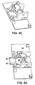
- Timing cam 52 further has a deadbolt boss 60 extending from it. Boss 60 engages a chamfered T slot 40 to move the deadbolt 30 between the extended position and the retracted position.
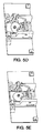
- Figs. 5A through 5E illustrate the operation of the timing cam 52.
- dead locking link cam portion 62 contacts the dead locking link 42 and moves it out of engagement with notch 38 (see Fig. 5B).
- boss 60 moves from position 70 (see Fig. 6) to position 71.
- boss 60 through engagement of slot 40 at point 71, moves deadbolt 30 to the retracted position (see Figs. 5C and 5D).
- timing cam 52 returns timing cam 52 to its original position, allowing the dead locking link 42 to engage the other notch 38 (see Fig. 5E).
- boss 60 moves from point 71 to point 72.
- the purpose for deadlocking the exit alarm lock deadbolt 30 is to make the mechanism more tamper resistant from the inside as well as the outside.
- the deadbolt 30 can not be forced into movement, except as a result of the key cylinder 50 or the pushbar 20.
- This design deadlocks the deadbolt 30 in both the extended (latched) and retracted positions.
- the extended position deadlocking prevents vandals from shaking or prying the deadbolt 30 back which would compromise the security of the opening.
- Retracted position deadlocking prevents a vandal surprised at the alarm horn from pulling the deadbolt 30 out to the extended position, which would compromise the alarm.
- the dead locking link 42 ensures that once the deadbolt 30 has reached either an extended or retracted position, it remains in that position unless the pushbar 30 is depressed or the device state is changed with the key cylinder 50.
- the dead locking link in exit device 10 operates on a swing/release principle which pivots about a horizontal axis parallel to the face of the door. This pivot design allows for low release forces, good impact resistance, minimal wear, and a more predictable release pattern than is possible with other conventional dead locking methods.
- the dead locking link 42 operates on three separate inputs: pushbar 20 depression, inside key cylinder 50 rotation, and exterior key cylinder rotation.
- the inside and outside key cylinders actuate the dead locking link 42 similarly.
- the outer diameter of timing cam 52 operably connected to the key cylinder contacts the dead locking link 42 causing it to lift (rotate) from the notch 38 in the deadbolt 30. Once the dead locking link 42 clears this notch 38, the deadbolt 30 is free to slide to a retracted or extended position.
- the interface utilized to release the deadlocking during depression of the pushbar 20 is similar to that of the timing cams 52.
- the pushbar 20 is pivotally connected to bell cranks 22, 24 which control and stabilize the motion of the pushbar 20.
- a "tooth like" cutout 39 on bell crank 22 contacts a surface of the dead locking link 42, causing it to rotate out of the deadbolt engagement slot 38.
- Continued bell cranks 22 rotation holds the dead locking link 42 in this rotated state which maintains the deadbolt 30 in a non-dead locked condition.
- the dead locking link 42 returns to its locked state, preferably via spring loading.
- the keying of the exit device 10 enables an authorized user to arm and disarm the device from the inside or outside of the door.
- the arming cycle serves two purposes: to mechanically extend (latch) the deadbolt 30 and to electrically engage the audible alarm trigger into its active state.
- the disarming cycle serves to retract the deadbolt and disengage the audible alarm, which leaves the device in an unlatched and passive state.
- the key rotates 360° to extend or retract the deadbolt 30. The first 90° moves the dead locking link 42 out of the way, the next 180° moves the deadbolt 30, and the remaining 90° returns the mechanism to the deadlocked state (see Figs. 5A through 5E). By utilizing the full 360° motion, the keying operates smoothly and with low turning input torque.
- the deadbolt 30 is moved using a chamfered "T" slot 40 cut into the deadbolt 30 and a boss 60 extending off the timing cam 52 to interface with the slot 40.
- the deadbolt 30 is moved when the boss 60 contacts the lower half of the chamfered "T” slot 40 while the timing cam 52 is being turned.
- the upper half of the "T” slot 40 provides clearance when the pushbar 30 or the opposite timing cam 52 is actuated.
- exit alarm lock The primary function of an exit alarm lock is to sound notification upon unauthorized egress, to prevent external vandalism from compromising the opening, and to maintain a safe and accessible exit for all building inhabitants to depart through the opening in an emergency or panic situation.
- the most significant advantage to this design is in the operation of its deadlocking/release mechanism as it relates to safe egress through the opening. Since the primary drive link (bell crank 22) is used to rotate the dead locking link 42 out of the way before the bell crank 22 contacts the deadbolt 30, there is no intermediate link used to create this mechanism timing. This timing is important, because the deadbolt 30 would not be able to move until the dead locking link 42 has adequately cleared the engagement slot 38 in the deadbolt 30. By eliminating an intermediate link, the possibility of malfunction or mechanism binding due to manufacturing variation or tolerance stack is inherently reduced.
- the swing design of the dead locking link 42 allows for extremely low actuation forces due to the ease with which the rotary bell crank motion can be converted to rotary motion of the dead locking link 42. This low deadlocking release force results in a low and predictable force actuation pattern for the device.
- the resistance to internal or external tampering is enhanced by the deadlock/deadbolt arrangement.
- the dead locking link axis (horizontal line parallel to the face of the door) is in approximate alignment with the dead locking link 42 center of mass and the deadlock/deadbolt lock interface. This allows the device to be much more tolerant to impact loading and shock, especially since most forms of external loading will act parallel to this described alignment.
- an impact "force" passes through the centercase housing 12 and into the dead locking link 42, the resultant acceleration of the dead locking link 42 will act to keep the dead locking link 42 is its approximate location (engaged with the deadbolt 30). Since the deadbolt 30 deadlocks in both the extended and retracted positions, it remains locked under various methods of attempted vandalism, better securing the device and opening from internal and external abuse.
- the bell crank/deadbolt interface allows consistent deadbolt 30 retraction even when the door is under a load to push the door open. This is achieved through the mechanical advantage designed into the bell crank 22, 24, pushbar 20 and deadbolt 30 geometries. After rotating the dead locking link 42 clear of the engagements slots 38, the bell crank 22 then contacts the deadbolt 30 directly, eliminating the need for an intermediate link, which would inherently add tolerance and manufacturing variation to the stability of the design. Due to the mechanical advantage of this design, requirements for loaded release forces are better met than in the prior art.
- exit alarm lock incorporates all of the described features, these features have utility when used separately or in combination and the use of all of the described features together is not necessary to solve the problem of a more vandal resistant and more reliable exit alarm lock.
Landscapes
- Business, Economics & Management (AREA)
- Emergency Management (AREA)
- Lock And Its Accessories (AREA)
- Burglar Alarm Systems (AREA)
Applications Claiming Priority (2)
| Application Number | Priority Date | Filing Date | Title |
|---|---|---|---|
| US13401499P | 1999-05-12 | 1999-05-12 | |
| US134014P | 1999-05-12 |
Publications (2)
| Publication Number | Publication Date |
|---|---|
| EP1054124A2 true EP1054124A2 (fr) | 2000-11-22 |
| EP1054124A3 EP1054124A3 (fr) | 2004-07-07 |
Family
ID=22461370
Family Applications (1)
| Application Number | Title | Priority Date | Filing Date |
|---|---|---|---|
| EP00304012A Withdrawn EP1054124A3 (fr) | 1999-05-12 | 2000-05-12 | Serrure antipanique |
Country Status (3)
| Country | Link |
|---|---|
| US (1) | US6409232B1 (fr) |
| EP (1) | EP1054124A3 (fr) |
| CA (1) | CA2308692A1 (fr) |
Cited By (2)
| Publication number | Priority date | Publication date | Assignee | Title |
|---|---|---|---|---|
| CN102644422A (zh) * | 2012-04-28 | 2012-08-22 | 北京诺卡汉威科技发展有限公司 | 逃生门锁系统及其启动方法 |
| CN102661092A (zh) * | 2012-04-28 | 2012-09-12 | 北京诺卡汉威科技发展有限公司 | 逃生门锁系统及其启动方法 |
Families Citing this family (11)
| Publication number | Priority date | Publication date | Assignee | Title |
|---|---|---|---|---|
| US6860528B2 (en) * | 2001-04-24 | 2005-03-01 | Ervos, Inc. | Exit device with a detachable touch bar assembly |
| US6769723B2 (en) * | 2002-08-30 | 2004-08-03 | Dor-O-Matic Inc. | Midrail mounted exit device |
| US7118141B2 (en) * | 2002-08-30 | 2006-10-10 | Dor-O-Matic, Inc. | Apparatus and method for securing an exit device to a door |
| US7632774B2 (en) * | 2006-03-30 | 2009-12-15 | Headwaters Technology Innovation, Llc | Method for manufacturing supported nanocatalysts having an acid-functionalized support |
| US7722096B2 (en) | 2006-04-05 | 2010-05-25 | Von Duprin, Inc. | Latchbolt for a door lock assembly |
| US7832777B2 (en) * | 2006-04-05 | 2010-11-16 | Von Duprin, Inc. | Door lock assembly |
| US7905522B1 (en) | 2006-09-14 | 2011-03-15 | Sargent Manufacturing Company | Exit pushbar with blocking mechanism |
| JP5071128B2 (ja) * | 2008-01-30 | 2012-11-14 | セイコーエプソン株式会社 | メディア処理装置 |
| CH700306A1 (de) * | 2009-01-22 | 2010-07-30 | Pilz Auslandsbeteiligungen Gmb | Verriegelungseinrichtung. |
| US10030411B2 (en) | 2014-10-23 | 2018-07-24 | Schlage Lock Company Llc | Windstorm damper device |
| KR102696368B1 (ko) * | 2023-10-26 | 2024-08-19 | 주식회사 올플랫폼 | 패닉 디바이스 및 이를 포함하는 플랫폼 스크린 도어 |
Citations (8)
| Publication number | Priority date | Publication date | Assignee | Title |
|---|---|---|---|---|
| GB419897A (en) * | 1933-08-28 | 1934-11-21 | Newman William & Sons Ltd | Improvements relating to door latches |
| US3432631A (en) * | 1966-12-19 | 1969-03-11 | Abe Deutscher | Alarm and safety lock device |
| US3614145A (en) * | 1970-08-19 | 1971-10-19 | Von Duprin Inc | Dogging device for panic exit latch and actuator assembly |
| US4167280A (en) * | 1978-07-24 | 1979-09-11 | Ingersoll-Rand Company | Panic exit mechanism |
| US4741563A (en) * | 1986-04-07 | 1988-05-03 | Von Duprin, Inc. | Center case assembly, and a universal, center case sub-assembly |
| DE3905191A1 (de) * | 1989-02-21 | 1990-08-23 | Kraft Franz | Panikstangengriffbeschlag |
| US4968070A (en) * | 1989-08-21 | 1990-11-06 | Adams Rite Manufacturing Company | Push bar dogging apparatus |
| US5605362A (en) * | 1993-11-01 | 1997-02-25 | Yale Security Inc. | Exit device having a deadbolt as its securing member |
Family Cites Families (11)
| Publication number | Priority date | Publication date | Assignee | Title |
|---|---|---|---|---|
| US376252A (en) | 1888-01-10 | Neil mctntyre | ||
| US930000A (en) * | 1908-10-29 | 1909-08-03 | Joseph Keenan | Lock. |
| US1441336A (en) | 1920-06-23 | 1923-01-09 | Mary E Flowers | Latch or bolt operating mechanism |
| US1535210A (en) * | 1921-09-03 | 1925-04-28 | Harry W Dyer | Exit door lock |
| US1676867A (en) | 1926-06-17 | 1928-07-10 | Bassick Co | Latch |
| US3765198A (en) * | 1970-11-04 | 1973-10-16 | Blumcraft Pittsburgh | Panic device for a door |
| US3819213A (en) * | 1972-09-29 | 1974-06-25 | Eaton Corp | Exit device |
| US3877262A (en) * | 1973-09-20 | 1975-04-15 | Emhart Corp | Emergency exit latch and actuator assembly |
| US4083590A (en) | 1977-02-02 | 1978-04-11 | Adams Rite Manufacturing Co. | Narrow stile panic exit actuator |
| US5219385A (en) * | 1990-12-13 | 1993-06-15 | Catwin Industrial Corporation | Lock for fire-escape door |
| US5947534A (en) * | 1995-06-19 | 1999-09-07 | Zarzycki, Jr.; Vincent W. | Panic exit device suitable for use with standard doors |
-
2000
- 2000-05-12 US US09/569,846 patent/US6409232B1/en not_active Expired - Lifetime
- 2000-05-12 CA CA002308692A patent/CA2308692A1/fr not_active Abandoned
- 2000-05-12 EP EP00304012A patent/EP1054124A3/fr not_active Withdrawn
Patent Citations (8)
| Publication number | Priority date | Publication date | Assignee | Title |
|---|---|---|---|---|
| GB419897A (en) * | 1933-08-28 | 1934-11-21 | Newman William & Sons Ltd | Improvements relating to door latches |
| US3432631A (en) * | 1966-12-19 | 1969-03-11 | Abe Deutscher | Alarm and safety lock device |
| US3614145A (en) * | 1970-08-19 | 1971-10-19 | Von Duprin Inc | Dogging device for panic exit latch and actuator assembly |
| US4167280A (en) * | 1978-07-24 | 1979-09-11 | Ingersoll-Rand Company | Panic exit mechanism |
| US4741563A (en) * | 1986-04-07 | 1988-05-03 | Von Duprin, Inc. | Center case assembly, and a universal, center case sub-assembly |
| DE3905191A1 (de) * | 1989-02-21 | 1990-08-23 | Kraft Franz | Panikstangengriffbeschlag |
| US4968070A (en) * | 1989-08-21 | 1990-11-06 | Adams Rite Manufacturing Company | Push bar dogging apparatus |
| US5605362A (en) * | 1993-11-01 | 1997-02-25 | Yale Security Inc. | Exit device having a deadbolt as its securing member |
Cited By (2)
| Publication number | Priority date | Publication date | Assignee | Title |
|---|---|---|---|---|
| CN102644422A (zh) * | 2012-04-28 | 2012-08-22 | 北京诺卡汉威科技发展有限公司 | 逃生门锁系统及其启动方法 |
| CN102661092A (zh) * | 2012-04-28 | 2012-09-12 | 北京诺卡汉威科技发展有限公司 | 逃生门锁系统及其启动方法 |
Also Published As
| Publication number | Publication date |
|---|---|
| CA2308692A1 (fr) | 2000-11-12 |
| EP1054124A3 (fr) | 2004-07-07 |
| US6409232B1 (en) | 2002-06-25 |
Similar Documents
| Publication | Publication Date | Title |
|---|---|---|
| US6409232B1 (en) | Exit alarm lock assembly with push pad pivotally interconnected to deadbolt | |
| US4237711A (en) | Lock mechanism | |
| JP4602569B2 (ja) | ゲートラッチ | |
| US5609371A (en) | Push pad trigger release exit device with infinite deadlocking | |
| CA1089894A (fr) | Serrure pour porte de sortie, comprenant plusieurs penes | |
| US20040195841A1 (en) | Lock assembly with two hook devices | |
| US20010029760A1 (en) | Lock mechanism | |
| EP3535467A2 (fr) | Mécanisme de verrouillage de sécurité/d'incendie à double fonction pour dispositifs coupe-feu | |
| WO2008135964A1 (fr) | Serrure à mortaise avec libération de pêne dormant | |
| KR20010071324A (ko) | 장붓구멍 자물쇠 | |
| US5651568A (en) | Privacy snib mechanism | |
| US5484177A (en) | Dual function lock mechanism | |
| CA3026702C (fr) | Pene en crochet destine a une serrure de porte | |
| CA2331418A1 (fr) | Verrou interconnecte avec sortie sans cle | |
| US6304177B1 (en) | Switching assembly for an exit alarm lock | |
| EP1899562A2 (fr) | Serrure a mortaise et element de raccord a verrouillage | |
| JP3805717B2 (ja) | 開口遮蔽装置用の錠装置 | |
| GB2306559A (en) | Locks | |
| KR200218006Y1 (ko) | 도어록의 자동 잠금 및 해제장치 | |
| JP4150766B2 (ja) | 本締り錠における防犯装置 | |
| JPH0454281Y2 (fr) | ||
| GB2426280A (en) | Lock with trigger responsive to opening of door | |
| EP3262256A1 (fr) | Serrure universelle avec mécanisme d'arrêt coulissant | |
| US317398A (en) | Philip mathes | |
| JP2001227213A (ja) | 扉 錠 |
Legal Events
| Date | Code | Title | Description |
|---|---|---|---|
| PUAI | Public reference made under article 153(3) epc to a published international application that has entered the european phase |
Free format text: ORIGINAL CODE: 0009012 |
|
| AK | Designated contracting states |
Kind code of ref document: A2 Designated state(s): AT BE CH CY DE DK ES FI FR GB GR IE IT LI LU MC NL PT SE |
|
| AX | Request for extension of the european patent |
Free format text: AL;LT;LV;MK;RO;SI |
|
| PUAL | Search report despatched |
Free format text: ORIGINAL CODE: 0009013 |
|
| AK | Designated contracting states |
Kind code of ref document: A3 Designated state(s): AT BE CH CY DE DK ES FI FR GB GR IE IT LI LU MC NL PT SE |
|
| AX | Request for extension of the european patent |
Extension state: AL LT LV MK RO SI |
|
| AKX | Designation fees paid | ||
| REG | Reference to a national code |
Ref country code: DE Ref legal event code: 8566 |
|
| STAA | Information on the status of an ep patent application or granted ep patent |
Free format text: STATUS: THE APPLICATION IS DEEMED TO BE WITHDRAWN |
|
| 18D | Application deemed to be withdrawn |
Effective date: 20050108 |