EP1053417B1 - Getriebebaueinheit - Google Patents
Getriebebaueinheit Download PDFInfo
- Publication number
- EP1053417B1 EP1053417B1 EP99962196A EP99962196A EP1053417B1 EP 1053417 B1 EP1053417 B1 EP 1053417B1 EP 99962196 A EP99962196 A EP 99962196A EP 99962196 A EP99962196 A EP 99962196A EP 1053417 B1 EP1053417 B1 EP 1053417B1
- Authority
- EP
- European Patent Office
- Prior art keywords
- elements
- housing
- gear
- transmission
- interior space
- Prior art date
- Legal status (The legal status is an assumption and is not a legal conclusion. Google has not performed a legal analysis and makes no representation as to the accuracy of the status listed.)
- Expired - Lifetime
Links
- 230000005540 biological transmission Effects 0.000 title claims abstract description 50
- 230000008878 coupling Effects 0.000 claims abstract description 17
- 238000010168 coupling process Methods 0.000 claims abstract description 17
- 238000005859 coupling reaction Methods 0.000 claims abstract description 17
- 230000009471 action Effects 0.000 claims abstract description 4
- 230000009347 mechanical transmission Effects 0.000 claims description 11
- 230000000295 complement effect Effects 0.000 claims 1
- 238000009434 installation Methods 0.000 abstract description 8
- 230000008901 benefit Effects 0.000 description 11
- 150000001875 compounds Chemical class 0.000 description 7
- 239000000243 solution Substances 0.000 description 7
- 238000000926 separation method Methods 0.000 description 5
- 238000005192 partition Methods 0.000 description 4
- 238000000034 method Methods 0.000 description 3
- 239000000969 carrier Substances 0.000 description 2
- 230000006835 compression Effects 0.000 description 2
- 238000007906 compression Methods 0.000 description 2
- 230000001419 dependent effect Effects 0.000 description 2
- 238000004090 dissolution Methods 0.000 description 2
- 230000008569 process Effects 0.000 description 2
- 230000001133 acceleration Effects 0.000 description 1
- 238000000418 atomic force spectrum Methods 0.000 description 1
- 230000004323 axial length Effects 0.000 description 1
- 238000006243 chemical reaction Methods 0.000 description 1
- 238000002485 combustion reaction Methods 0.000 description 1
- 238000001816 cooling Methods 0.000 description 1
- 230000000694 effects Effects 0.000 description 1
- 230000017525 heat dissipation Effects 0.000 description 1
- 238000003780 insertion Methods 0.000 description 1
- 230000037431 insertion Effects 0.000 description 1
- 238000004519 manufacturing process Methods 0.000 description 1
- 230000002093 peripheral effect Effects 0.000 description 1
- 230000008092 positive effect Effects 0.000 description 1
- 238000007789 sealing Methods 0.000 description 1
- 230000035939 shock Effects 0.000 description 1
Images
Classifications
-
- F—MECHANICAL ENGINEERING; LIGHTING; HEATING; WEAPONS; BLASTING
- F16—ENGINEERING ELEMENTS AND UNITS; GENERAL MEASURES FOR PRODUCING AND MAINTAINING EFFECTIVE FUNCTIONING OF MACHINES OR INSTALLATIONS; THERMAL INSULATION IN GENERAL
- F16H—GEARING
- F16H63/00—Control outputs from the control unit to change-speed- or reversing-gearings for conveying rotary motion or to other devices than the final output mechanism
- F16H63/02—Final output mechanisms therefor; Actuating means for the final output mechanisms
- F16H63/30—Constructional features of the final output mechanisms
- F16H63/3023—Constructional features of the final output mechanisms the final output mechanisms comprising elements moved by fluid pressure
- F16H63/3026—Constructional features of the final output mechanisms the final output mechanisms comprising elements moved by fluid pressure comprising friction clutches or brakes
-
- F—MECHANICAL ENGINEERING; LIGHTING; HEATING; WEAPONS; BLASTING
- F16—ENGINEERING ELEMENTS AND UNITS; GENERAL MEASURES FOR PRODUCING AND MAINTAINING EFFECTIVE FUNCTIONING OF MACHINES OR INSTALLATIONS; THERMAL INSULATION IN GENERAL
- F16H—GEARING
- F16H57/00—General details of gearing
- F16H57/02—Gearboxes; Mounting gearing therein
-
- F—MECHANICAL ENGINEERING; LIGHTING; HEATING; WEAPONS; BLASTING
- F16—ENGINEERING ELEMENTS AND UNITS; GENERAL MEASURES FOR PRODUCING AND MAINTAINING EFFECTIVE FUNCTIONING OF MACHINES OR INSTALLATIONS; THERMAL INSULATION IN GENERAL
- F16H—GEARING
- F16H57/00—General details of gearing
- F16H2057/005—Mounting preassembled units, i.e. using pre-mounted structures to speed up final mounting process
-
- F—MECHANICAL ENGINEERING; LIGHTING; HEATING; WEAPONS; BLASTING
- F16—ENGINEERING ELEMENTS AND UNITS; GENERAL MEASURES FOR PRODUCING AND MAINTAINING EFFECTIVE FUNCTIONING OF MACHINES OR INSTALLATIONS; THERMAL INSULATION IN GENERAL
- F16H—GEARING
- F16H57/00—General details of gearing
- F16H57/02—Gearboxes; Mounting gearing therein
- F16H2057/02039—Gearboxes for particular applications
- F16H2057/02043—Gearboxes for particular applications for vehicle transmissions
- F16H2057/02047—Automatic transmissions
-
- Y—GENERAL TAGGING OF NEW TECHNOLOGICAL DEVELOPMENTS; GENERAL TAGGING OF CROSS-SECTIONAL TECHNOLOGIES SPANNING OVER SEVERAL SECTIONS OF THE IPC; TECHNICAL SUBJECTS COVERED BY FORMER USPC CROSS-REFERENCE ART COLLECTIONS [XRACs] AND DIGESTS
- Y10—TECHNICAL SUBJECTS COVERED BY FORMER USPC
- Y10T—TECHNICAL SUBJECTS COVERED BY FORMER US CLASSIFICATION
- Y10T74/00—Machine element or mechanism
- Y10T74/21—Elements
- Y10T74/2186—Gear casings
Definitions
- the invention relates to a gear unit, in particular with dne features from the preamble of claim 1.
- the gear units which are either purely mechanical Have transmission components or a combination of one hydrodynamic converter or a hydrodynamic coupling with a downstream mechanical gear set usually have one Housing, which with regard to its inner contour of the design and Connection to the housing of the individual gear elements is adapted and usually have inner inserts that undesirable the inner diameter to reduce.
- the individual switching devices are usually operated by pressurizing over hydraulic pistons. To reset when releasing the brake or Coupling devices are either one in each of these systems large disc spring is provided, which is effective on a piston, or a large number of individual compression springs arranged on a carrier plate are and in turn act on a piston.
- the compression springs are included always viewed in the radial direction in an area outside the radial Extension of the brake or clutch devices arranged or in Area of the outer circumference or extend in an axial direction Area which is radially within the clutch or Braking devices predetermined space is.
- the support takes place thereby either on projections of the housing inner wall, further the housing cover is used for support in the axial direction.
- the object of the invention was therefore to provide a gear unit develop in which the disadvantages mentioned are avoided. in the individual is on a simpler case design as well as a simple one Sealing and fastening the housing cover to the gear housing remedy.
- the gearbox should also be checked in this condition be that the housing is open.
- the device for resetting the device is connected Actuators, especially the cylinder-piston device and individual gear elements stationary on the housing by means of at least two Means in the form of rod-shaped guide elements for connecting Gear elements in the radial direction or in the circumferential direction. This extend essentially over an area in which the Connection provided gear elements are arranged.
- the rod-shaped guide elements are the cylindrical interior assigned and arranged in an area outside of it, wherein the assignment is such that the rod-shaped guide elements be provided outside an area which is in the installed position of the Gearbox considers the largest dimension of the cylindrical interior corresponds to the height of the gear unit.
- the arrangement is in the cross section of the Gear housing viewed in the corner areas, through the Intersection between the cylindrical interior and a theoretical one Generatable square with a side dimension greater than or equal to that Diameter of the interior is writable, which is theoretically generate square and the interior identical axes of symmetry exhibit.
- a rectangular one Housing with cylindrical interior the material-intensive corner areas used to accommodate the guide elements.
- the arrangement of the Guiding elements thus take place outside the perpendicular bisector.
- the Guide elements are guided in recesses, which with the cylindrical interior are connected.
- the arrangement is preferably carried out the guide elements always symmetrical. This has the advantage that the manufacturing cost for the gear elements and that Gear housing can be minimized, furthermore the assembly effort, since there is no need to pay attention to how the individual recesses or Through openings on the gear elements for receiving the Guide elements must be designed.
- braking devices in the form of Multi-disc brakes, partitions, actuators for brake or Coupling devices, for example in the form of pistons, disk carriers or the like can be viewed.
- the rod-shaped elements preferably have an axial extension have the same or constant diameter. This has the advantage that assembly regardless of the installation direction of the rod-shaped elements can be done. However, depending on the design of the Overall gear unit with the use of rod-shaped elements different diameters over the axial extension. In this case however, assembly will usually take place from two sides.
- the cross section of the rod-shaped guide element is preferred circular. However, there are also versions with a square cross section or any cross-section possible.
- the gear unit can be a purely mechanical gear unit be executed.
- each rod-shaped extends Guide element preferably over the entire axial extent of the Transmission unit.
- the gear unit As The hydrodynamic-mechanical compound transmission is the rod-shaped one Guide element provided at least with an axial length, which the axial extent of the mechanical transmission part, based on the Total gear unit, corresponds.
- it is always necessary that the axial extension of the guide elements of the axial extension of the corresponds to this gear elements to be supported.
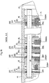
- FIG. 1 illustrates an example using a specific type of gearbox in the Axial section of the solution according to the invention.
- the gear unit is as hydrodynamic-mechanical compound transmission 1 executed.
- the hydrodynamic-mechanical compound transmission 1 comprises a first one hydrodynamic transmission part 2 in the form of a hydrodynamic speed / torque converter 3 and a second mechanical transmission part 4.
- the mechanical transmission part 4 comprises a mechanical speed / torque converter 5 and one, this in the power flow direction in Traction mode downstream group set.
- the mechanical speed / torque converter 5 is a modified Ravigneaux planetary gear set executed. This comprises a first planetary gear set 7 and a second Planetary gear set 8, which has a shared planetary gear carrier 9 exhibit. This provides the coupling between a gear element of the first and second planetary gear set.
- the first planetary gear set 7 includes a sun gear 7.1, planet gears 7.2 and a ring gear 7.3.
- the second Planetary gear set 8 includes a sun gear 8.1, planet gears 8.2 and one Ring gear 8.3.
- the groupset 6 comprises at least one planetary gear set 10, which one Sun gear 10.1, planet gears 10.2, a ring gear 10.3 and a web 10.4 having.
- the first stator L1 is on the turbine side between the turbine wheel T. and the pump wheel P arranged and reversibly supported by a bearing.
- the first stator L1 can be connected in a rotationally fixed manner to a first stator shaft 15, a free wheel 16 between the first stator L1 and the stator shaft 15 is provided, which is designed such that it has a moment on the first stator shaft 15 transmits when the first stator L1 turns in reverse Direction, i.e. opposite direction of rotation, to the turbine wheel T and which idles when the first stator L1 in the normal direction, i.e. in same direction of rotation as the turbine wheel T rotates.
- the second idler L2 is between the turbine wheel T and the pump wheel P on the pump side arranged and via a second stator shaft 17 with the housing 11 coupled. Between the second stator L2 and the second stator shaft 17 a second freewheel 18 is arranged, by means of which the second stator L2 can be coupled to the second stator shaft 17, but only then, if the second idler L2 in the opposite direction to Turbine wheel T rotates.
- the pump wheel P is rotatably connected to a pump wheel shaft 19, which is rotatably supported by a bearing in the housing 11.
- Turbine wheel shaft 13 is with the sun gear 8.1 of the second Planetary gear set 8 of the mechanical speed / torque converter 5 coupled.
- the turbine wheel T and the sun wheel 8.1 are preferably of second planetary gear set 8 on a common shaft, here the Turbine wheel shaft 13, arranged.
- the turbine shaft 13 also supports the clutch disc 20 of the first clutch K1.
- the first clutch K1 also has a clutch cover 21 which mates with the first Stator shaft 15 is coupled.
- the first stator L1 is over the first idler shaft 15 with sun gear 7.1 of first planetary gear set 7 of the mechanical speed / torque converter 5 connectable.
- the Coupling cover 21 is preferably in one piece with the first Stator shaft 15 connected.
- the first stator shaft 15 is a hollow shaft executed, which surrounds the stator shaft 13 in the circumferential direction.
- the clutch cover 21 of the first clutch K1 is preferred disc-shaped element 22 connected and forms a structural with this Unit, on the outer peripheral region 23 of which the first braking device B1 can attack.
- the first braking device B1 is used for fixing of the first stator L1 via the stator shaft 15 and / or the first Sun gear 7.1 of the first planetary gear set 7 of the mechanical Speed / torque converter 5.
- Other switching elements, here the Switching elements in the form of braking devices B2 and B3 are the individual planetary gear sets 7 and 8 of the mechanical speed / torque converter 5 assigned.
- the second is Brake element B2 the ring gear 7.3 of the first planetary gear set 7 and that third brake element B3 the ring gear 8.3 of the second planetary gear set 8 of the mechanical speed / torque converter 5 assigned.
- the Coupling of the mechanical speed / torque converter 5 with the Transmission input shaft E via the hydrodynamic speed / torque converter 3 or its bridging over the Bridging clutch 14 is carried out by coupling the Turbine wheel T or the turbine wheel shaft 13 with a first Gear element of the mechanical speed / torque converter 5 and of the first stator L1 with a further second gear element of the mechanical speed / torque converter 5.
- First Gear element of the mechanical speed / torque converter 5 here functions the sun gear 8.1 of the second planetary gear set 8.
- the gear element acts as the sun gear 7.1 of the first planetary gear set 7.
- the shafts coupled with the two sun gears 7.1 and 8.1, here the first stator shaft 15 and turbine wheel shaft 13 function as Input shafts of the mechanical speed / torque converter 5.
- Another third gear element is on the group set 6 with the Transmission output shaft A connected.
- the third gear element of the mechanical speed / torque converter 5 is with the entrance, which is from a first Gear element of the group set 6 is formed, connected. This connection is preferably made via a rotationally fixed coupling third gear element of the mechanical speed / torque converter 5 and first gear element of the group set 6 realized.
- the first gear element of the Group set 6 is formed by its planet carrier 10.4.
- a second Gear element of the group set 6 is rotatably with the Transmission output shaft A of the hydrodynamic-mechanical Compound gear 1 connected.
- the second gear element acts in illustrated case the ring gear 10.3 of the planetary gear set 10 of the Group set 6.
- Group set 6 each have a further coupling device, here the second Coupling device K2 and another braking device, here the fourth Brake device B4 assigned.
- the fourth braking element serves the Determination of the sun gear 10.1 of the group set 6.
- the second Coupling device K2 enables the rigid coupling between the Planet carrier 10.4 and the sun gear 10.1 of the planetary gear set 10 of the Group set 6.
- the intermediate elements are each designated B 1z , B 2z , B 3z and B 4z .
- the friction-bearing elements B 1n to B 4n form the outer plates.
- the outer plates are stationary, while the inner plates, which are formed by the intermediate elements B 1zn to B 4zn , are coupled to the gear element to be braked.
- the outer plates are fixed in position via the rod-shaped guide elements 40. These preferably extend at least over the axial extent of the mechanical transmission part 4.
- the housing 11 has a constant inner diameter d 1 essentially over the axial extent.
- d 1 essentially over the axial extent.
- the gear housing 11 itself is designed, at least in the area where the mechanical gear part 4 is accommodated, in such a way that it has an essentially cylindrical inner cross section.
- the transmission housing When viewed in the axial direction, the transmission housing preferably has an essentially constant inside diameter in the area of the mechanical transmission part 4. The inside diameter is designed in such a way that essentially the rotating gear elements and components can rotate freely using the maximum possible installation space.
- the guide element 40 is preferably made in one piece, but can also consist of several sections. In the unassembled state of the mechanical transmission part 4, the interior, which is denoted here by 41, is essentially empty.
- the rod-shaped guide elements are first brought into the corresponding positions or suspended in a corresponding manner on the gear housing and the individual gear elements are threaded onto these guide elements in succession in accordance with the desired arrangement.
- All components of the mechanical transmission part can be threaded one after the other from the separation point T to the housing cover 42 during assembly.
- This offers the advantage that with the threading technique and the constant inner diameter, the individual components in the mechanical gear part 4 can be interchanged and can thus be realized in a simple manner with the same gear housing or the same dimensions of the gear unit center drives or all-wheel drives.
- the assembly is carried out only from one side and in the case shown from the side of the cover 42.
- the assembly is simple and can be implemented within a very short time.
- the arrangement of the individual planetary gear sets can be interchanged.
- different output variants can be implemented.
- the individual gear elements are axially fixed by Belay means, for example in the form of circlips or Attacks.
- Belay means for example in the form of circlips or Attacks.
- Partitions 44, 45, 46 and 47 guided.
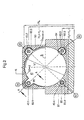
- FIG. 2 illustrates a cross section corresponding to a view AA according to FIG. 1.
- the gear housing 11 can be seen, which in the illustrated case can be divided into two partial areas 50 and 51.
- the first partial area 50 forms the upper housing part in the installed position
- the second partial area 51 forms the housing part arranged below the gear symmetry axis S in the installed position.
- the gear housing 11 has an essentially cylindrical inner contour 53 which encloses an inner space 41.
- the inner contour 53 can be described by the diameter d 1 . As already explained in detail in the explanations relating to FIG. 1, this extends essentially over the entire axial extent of the mechanical transmission part 4.
- Means for receiving and connecting the transmission elements in the radial direction and for securing against rotation in the circumferential direction are assigned. These means are formed by the guide elements 40.1 to 40.4. These are assigned to the inner circumference 53 described by the diameter d 1 in such a way that they are arranged in the installed position of the gear unit 1 at a height H1 to H4 which, with respect to the dimensions, is smaller than the dimension H5 described by the maximum extent of the inner contour 53 in the installed position in the vertical direction is.
- the guide elements are therefore, as illustrated in FIG. 2, arranged in the corner regions 54, 55, 56 and 57 of the housing 11, the corner regions being able to be described by assigning a square or rectangle to the inner contour 53.
- the corner portions 54 to 57 are thereby theoretically described in the installed position by assignment of the square Q in which the circumscribed by the inner contour 53 diameter d is 1 arranged in the square, and both the theoretically relied on for viewing square Q theoretical and the inner diameter d of the inner contour 53 of the housing has the same axes of symmetry S1 and S2.
- Appropriate recesses are provided in the housing to accommodate the guide elements. These are each designated 60.1 to 60.4 for the individual guide elements. The arrangement of these recesses 60.1 to 60.4 in the housing takes place outside of an area on the gear housing, which is described by the maximum extent of the inner contour of the respective axis of symmetry in the height or width direction of the gear unit.
- the gear housing 11 itself can be equipped with a relatively thin housing wall in the areas free of the machined recesses 60.1 to 60.4.
- the recesses 60.1 to 60.3 form so-called engagement pockets into which the guide elements 40.1 to 40.4 can be inserted.
- FIG. 1 a possibility for hanging in or for floating mounting of the guide elements 40.1 to 40.4 is provided.
- This is designated 62 in FIG. 1.
- the guide elements can also be guided in the intermediate walls, which extend in the radial direction over the entire interior.
- 2 illustrates, for example, the connection of the friction surface-bearing element B 31 .
- four possible variants are shown schematically in FIG. 2 in a simplified manner.
- the same axial securing elements are preferably used for the axial fixing of an element.
- the axial securing on the guide element 40.1 takes place by using insertion plates, in the guide element 40.3 by means of a locking ring 64 and on the guide element 40.4 by sleeves 65.
- gear elements are preferably designed in such a way that, in addition to their circular cross section, they have projections on which the recesses or through openings are incorporated. This offers the advantage that the remaining installation space, in particular the cylindrical interior 41, can be used essentially to the full and does not contain any additional disruptive elements.
- a surface can be used for power transmission which essentially corresponds to the surface that can be described by the inner diameter d 1 .
- the gear elements are preferably connected in all four possible corner areas 53 to 57.
- the guide elements 40.1 to 40.4 and the corresponding protrusions on the gear elements accordingly viewed at a constant distance in Circumferential direction based on the inner contour 53 of the gear unit 1 arranged.
- To prevent rotation at least two guide elements are required in the circumferential direction.
- the braking devices B1 to B4 are preferably provided with one device equipped to reset actuators.
- For this purpose are each between two adjacent friction surface bearing Elements provided a spring storage unit, which is also from the Guide elements, according to Fig. 1 guided the guide element 40.1 and when generating the frictional connection between the friction surface bearing Elements and the intermediate element is biased.
- a spring-loaded unit F1 or B2, F2, B3-F3 and B4, F4 is provided between the friction surface bearing elements of the braking device B1 a spring-loaded unit F1 or B2, F2, B3-F3 and B4, F4 is provided.
- the spring-loaded units are always outside of the arranged intermediate surface, so that in this regard no collision between the spring-loaded units and the can occur friction-bearing intermediate elements.
- the Spring storage device thus acts at least indirectly via the elements bearing the friction surface on the actuating element, in particular a piston.
- the actuators i.e. H. the pistons, can for example, hydraulically or pneumatically.
- the individual friction-bearing elements and the intermediate elements must then no longer dress yourself. There is always a forced separation at least in the area in which the spring storage unit is arranged is.
- the arrangement of the spring storage units between the individual friction surface-bearing elements also has the advantage that the Dimensions of the friction surface bearing elements in the radial direction are not more by the size of the internal dimensions of the gearbox Consideration of the space required for the device for at least indirect provision is dependent on actuators.
- the arrangement of spring-loaded units between the frictionally an intermediate element that can be connected to one another Elements also offers the advantage of a space-saving design the reset device in the axial direction, which in turn relates to the Gearbox length has a positive effect.
Landscapes
- Engineering & Computer Science (AREA)
- General Engineering & Computer Science (AREA)
- Mechanical Engineering (AREA)
- Physics & Mathematics (AREA)
- Fluid Mechanics (AREA)
- General Details Of Gearings (AREA)
- Structure Of Transmissions (AREA)
- Braking Arrangements (AREA)
- Telephone Function (AREA)
- Vehicle Body Suspensions (AREA)
- Percussion Or Vibration Massage (AREA)
Description
- Buksch, M.: ZF-Fünfgang-Automatgetriebe für Pkw, VDI-Bericht 878 (1991)
- Mitesko, G.: Viergang-Planetengetriebe für Personenkraftwagen mit dem hydrodynamiscen Drehmomentenwandler in der Leistungsverzweigung, Automobilindustrie (1995) 5, Seite 597 - 691
- Klement, W.: Die Entwicklung der DIWA-Getriebe; Verkehr und Technik (1997) 7, Seite 301 - 303 - US-A 5 653 321, die dem Oberbegiff des Anspuchs 1 entspricht,
- GB-A-1 411 361
- EP-A-0 757 189
- selbsttätige stufenlose Einstellung des Verhältnisses zwischen der Anund Abtriebsdrehzahl entsprechend der Belastung auf der Abtriebsseite
- Zurverfügungstehen des maximalen Drehmomentes für einen Anfahrvorgang mit hoher Beschleunigung;
- Möglichkeit der Wärmeabfuhr durch Fremd- oder Oberflächenkühlung
- Trennung des hydrodynamischen Drehzahl-/Drehmomentenwandlers vom Abtrieb, insbesondere vom Fahrzeug bei kleinen Antriebsdrehzahlen und Übertragung eines geringen Restmomentes, so daß ein Abwürgen der Antriebsmaschine von der Abtriebsseite her nicht möglich ist
- verschleißfreie Leistungsübertragung
Claims (6)
- Getriebebaueinheit1.1 mit einem Getriebegehäuse;1.2 mit einem dem Gehäuse in Einbaulage in axialer Richtung zugeordneten Gehäusedeckel;1.3 das Getriebegehäuse weist einen im wesentlichen zylindrischen Innenraum zur Aufnahme einzelner Getriebeelemente auf;1.4 mit einer Vorrichtung zur wenigstens mittelbaren Rückstellung von Betätigungselementen kraftschlüssiger Kupplungs- und/oder Bremseinrichtungen mit wenigstens zwei reibflächentragenden Elementen, deren Reibflächen über ein weiteres reibflächentragendes Zwischenelement miteinander reibschlüssig verbindbar sind;1.5 es sind wenigstens zwei Mittel zur Anbindung eines einzelnen Getriebeelementes ortsfest gegenüber dem Gehäuse und/oder der Vorrichtung zur wenigstens mittelbaren Rückstellung der Betätigungselemente kraftschlüssiger Kupplungs- und/oder Bremseinrichtungen vorgesehen; gekennzeichnet durch die folgenden Merkmale:1.6 die Mittel sind dem durch den Durchmesser beschriebenen Innenumfang des Innenraumes derart zugeordnet, dass diese in Einbaulage der Getriebebaueinheit auf einer Höhe angeordnet sind, welche bezüglich der Abmessungen kleiner ist als die durch die maximale Erstreckung der Innenkontur in Einbaulage in Höhenrichtung beschriebene Abmessung H5 ;1.7 die Mittel umfassen mit dem Innenraum verbundene Ausnehmungen in der Getriebegehäusewand, welche zur Führung dazu komplementärer Vorsprünge an den Getriebeelementen und/oder der Vorrichtung zur wenigstens mittelbaren Rückstellung der Betätigungselemente der kraftschlüssigen Kupplungs- und/oder Bremseinrichtungen ausgebildet sind oder in welcher sich in axialer Richtung der Getriebebaueinheit streckende stabförmige Elemente angeordnet sind, auf welche die Getriebeelemente und/oder die Vorrichtung zur wenigstens mittelbaren Rückstellung der Betätigungselemente aufsteckbar oder einsteckbar sind;1.8 der Gehäusedeckel ist frei von Axialkraftwirkung durch die Vorrichtung zur wenigstens mittelbaren Rückstellung der Betätigungselemente und/oder der Getriebeelemente.
- Getriebebaueinheit nach Anspruch 1, dadurch gekennzeichnet, daß der zylindrische Innenraum über die gesamte axiale Erstreckung in Einbaulage einen im wesentlichen konstanten Durchmesser aufweist.
- Getriebebaueinheit nach einem der Ansprüche 1 oder 2, dadurch gekennzeichnet, daß die Zuordnung der Mittel in den Eckenbereichen des Gehäuses erfolgt, welches durch die Schnittmenge von zylindrischem Innenraum und einem theoretisch bildbaren Qudradt Qtheoretisch mit einer Seitenabmessung >/= dem Durchmesser des zylindrischen Innraumes beschreibbar ist, wobei das theoretisch bildbare Quadrat und der Innenraum identische Symmetrieachsen aufweisen.
- Getriebebaueinheit nach Anspruch 3, dadurch gekennzeichnet, daß die Mittel in allen vier Eckenbereichen mit im wesentlichen in Umfangsrichtung des innenraumes betrachtet konstanten Abstand zueinander angeordnet sind.
- Getriebebaueinheit nach einem der Ansprüche 1 bis 4, dadurch gekennzeichnet, daß den einzeinen Getriebeelementen und/oder der Vorrichtung zur Rückstellung der Betätigungselemente Mittel zur Begrenzung und/oder Vermeidung axialer Bewegbarkeit geordnet sind.
- Getriebebaueinheit nach einem der Ansprüche 1 bis 5, gekennzeichnet durch die folgenden Merkmale:6.1 mit einem mechanischen Getriebeteil und einem hydrodynamischen Getriebeteil;6.2 der zylindrische Innenraum des Getriebegehäuses weist in aoialer Richtung betrachtet wenigstens über den Bereich des mechanischen Getriebeteils einen konstanten Durchmesser auf.
Applications Claiming Priority (3)
| Application Number | Priority Date | Filing Date | Title |
|---|---|---|---|
| DE19855762 | 1998-12-03 | ||
| DE19855762A DE19855762C2 (de) | 1998-12-03 | 1998-12-03 | Getriebebaueinheit |
| PCT/EP1999/009366 WO2000032963A1 (de) | 1998-12-03 | 1999-12-02 | Getriebebaueinheit |
Publications (2)
| Publication Number | Publication Date |
|---|---|
| EP1053417A1 EP1053417A1 (de) | 2000-11-22 |
| EP1053417B1 true EP1053417B1 (de) | 2003-08-27 |
Family
ID=7889828
Family Applications (1)
| Application Number | Title | Priority Date | Filing Date |
|---|---|---|---|
| EP99962196A Expired - Lifetime EP1053417B1 (de) | 1998-12-03 | 1999-12-02 | Getriebebaueinheit |
Country Status (7)
| Country | Link |
|---|---|
| US (1) | US6427820B1 (de) |
| EP (1) | EP1053417B1 (de) |
| JP (1) | JP2002531786A (de) |
| KR (1) | KR100706395B1 (de) |
| AT (1) | ATE248306T1 (de) |
| DE (2) | DE19855762C2 (de) |
| WO (1) | WO2000032963A1 (de) |
Families Citing this family (2)
| Publication number | Priority date | Publication date | Assignee | Title |
|---|---|---|---|---|
| US20060146262A1 (en) * | 2005-01-03 | 2006-07-06 | Chunghwa Picture Tubes., Ltd | Method and the plasma display panel with an improvement of overflow effect of anisotropic conductive adhesive film |
| US10041549B2 (en) * | 2016-01-18 | 2018-08-07 | Deere & Company | Disk pack cooling arrangement |
Family Cites Families (11)
| Publication number | Priority date | Publication date | Assignee | Title |
|---|---|---|---|---|
| US3475992A (en) * | 1967-12-26 | 1969-11-04 | Gen Motors Corp | Power transmission |
| FR2214353A5 (de) | 1973-01-11 | 1974-08-09 | Peugeot & Renault | |
| US3877321A (en) * | 1973-10-23 | 1975-04-15 | Gen Motors Corp | Transmission having hydraulic preload motor for axially positioning brake components |
| JPS606666Y2 (ja) * | 1979-11-06 | 1985-03-04 | 株式会社小松製作所 | 多板クラツチの戻し装置 |
| JPH0765650B2 (ja) * | 1988-06-06 | 1995-07-19 | 日産自動車株式会社 | 自動変速機用ワンウエイクラッチのインナレース芯出し構造 |
| JP2558970Y2 (ja) * | 1990-02-20 | 1998-01-14 | 株式会社エクセディ | 自動変速機のディスクブレーキ装置 |
| JP3116488B2 (ja) * | 1991-12-19 | 2000-12-11 | アイシン・エィ・ダブリュ株式会社 | 自動変速機 |
| JP3436590B2 (ja) | 1994-07-28 | 2003-08-11 | ジヤトコ株式会社 | 締結装置 |
| JP3407487B2 (ja) | 1995-07-31 | 2003-05-19 | アイシン・エィ・ダブリュ株式会社 | 自動変速機 |
| JP3359523B2 (ja) * | 1996-12-27 | 2002-12-24 | アイシン・エィ・ダブリュ株式会社 | 自動変速機 |
| DE19855761C2 (de) * | 1998-12-03 | 2000-12-21 | Voith Turbo Kg | Getriebebaueinheit |
-
1998
- 1998-12-03 DE DE19855762A patent/DE19855762C2/de not_active Expired - Fee Related
-
1999
- 1999-12-02 DE DE59906767T patent/DE59906767D1/de not_active Expired - Lifetime
- 1999-12-02 WO PCT/EP1999/009366 patent/WO2000032963A1/de not_active Ceased
- 1999-12-02 JP JP2000585570A patent/JP2002531786A/ja active Pending
- 1999-12-02 EP EP99962196A patent/EP1053417B1/de not_active Expired - Lifetime
- 1999-12-02 AT AT99962196T patent/ATE248306T1/de not_active IP Right Cessation
- 1999-12-02 KR KR1020007008506A patent/KR100706395B1/ko not_active Expired - Fee Related
- 1999-12-02 US US09/601,164 patent/US6427820B1/en not_active Expired - Fee Related
Also Published As
| Publication number | Publication date |
|---|---|
| DE19855762A1 (de) | 2000-06-29 |
| US6427820B1 (en) | 2002-08-06 |
| DE59906767D1 (de) | 2003-10-02 |
| KR100706395B1 (ko) | 2007-04-10 |
| KR20010040635A (ko) | 2001-05-15 |
| JP2002531786A (ja) | 2002-09-24 |
| WO2000032963A1 (de) | 2000-06-08 |
| ATE248306T1 (de) | 2003-09-15 |
| DE19855762C2 (de) | 2002-07-04 |
| WO2000032963A9 (de) | 2001-04-19 |
| EP1053417A1 (de) | 2000-11-22 |
Similar Documents
| Publication | Publication Date | Title |
|---|---|---|
| DE3935570C2 (de) | Gangwechselgetriebe für Kraftfahrzeuge | |
| DE69905526T2 (de) | Automatisches Getriebe für Fahrzeuge | |
| DE202007007702U1 (de) | Mehrganggetriebe | |
| DE3741757C2 (de) | Automatikgetriebe | |
| EP3049694B1 (de) | Drehschwingungsdämpferanordnung in einem antriebsstrang eines fahrzeugs | |
| DE3604393C2 (de) | ||
| DE3638422C2 (de) | ||
| DE69614737T2 (de) | Automatisches Getriebe für Fahrzeuge | |
| EP1053418B1 (de) | Verfahren zur montage einer getriebebaueinheit | |
| EP1203175A1 (de) | Drehmomentwandler mit torsionsschwingungsdämpfer | |
| DE19855762C2 (de) | Getriebebaueinheit | |
| EP1051576B1 (de) | Getriebebaueinheit | |
| DE19907037C2 (de) | Hydrodynamisch, mechanisches Verbundgetriebe | |
| DE19958370B4 (de) | Vorrichtung zur Rückstellung von Betätigungselementen kraftschlüssiger Kupplungs- und/oder Bremseinrichtungen | |
| DE19855761C2 (de) | Getriebebaueinheit | |
| EP1646808B1 (de) | Mehrstufen-automatgetriebe mit drei planetenradsätzen | |
| DE10333429A1 (de) | Mehrstufen-Automatgetriebe mit drei Planetenradsätzen | |
| DE3615367C2 (de) | ||
| DE19809472C2 (de) | Hydrodynamisch-mechanisches Mehrgangverbundgetriebe | |
| WO2004048167A1 (de) | Anfahreinheit und getriebebaueinheit | |
| DE10132978B4 (de) | Synchronisiereinrichtung für ein Planetengetriebe | |
| EP1442230A1 (de) | Kombinierte schwungrad-dämpfungseinheit | |
| WO1999045295A1 (de) | Hydrodynamisch-mechanisches mehrgangverbundgetriebe | |
| DE20320470U1 (de) | Mehrstufen-Automatgetriebe mit drei Planetenradsätzen | |
| DE29803789U1 (de) | Hydrodynamisch-mechanisches Mehrgangverbundgetriebe |
Legal Events
| Date | Code | Title | Description |
|---|---|---|---|
| PUAI | Public reference made under article 153(3) epc to a published international application that has entered the european phase |
Free format text: ORIGINAL CODE: 0009012 |
|
| 17P | Request for examination filed |
Effective date: 20000718 |
|
| AK | Designated contracting states |
Kind code of ref document: A1 Designated state(s): AT BE CH CY DE DK ES FI FR GB GR IE IT LI LU MC NL PT SE |
|
| 17Q | First examination report despatched |
Effective date: 20020726 |
|
| GRAH | Despatch of communication of intention to grant a patent |
Free format text: ORIGINAL CODE: EPIDOS IGRA |
|
| GRAH | Despatch of communication of intention to grant a patent |
Free format text: ORIGINAL CODE: EPIDOS IGRA |
|
| GRAA | (expected) grant |
Free format text: ORIGINAL CODE: 0009210 |
|
| AK | Designated contracting states |
Designated state(s): AT BE CH CY DE DK ES FI FR GB GR IE IT LI LU MC NL PT SE |
|
| PG25 | Lapsed in a contracting state [announced via postgrant information from national office to epo] |
Ref country code: NL Free format text: LAPSE BECAUSE OF FAILURE TO SUBMIT A TRANSLATION OF THE DESCRIPTION OR TO PAY THE FEE WITHIN THE PRESCRIBED TIME-LIMIT Effective date: 20030827 Ref country code: IT Free format text: LAPSE BECAUSE OF FAILURE TO SUBMIT A TRANSLATION OF THE DESCRIPTION OR TO PAY THE FEE WITHIN THE PRESCRIBED TIME-LIMIT;WARNING: LAPSES OF ITALIAN PATENTS WITH EFFECTIVE DATE BEFORE 2007 MAY HAVE OCCURRED AT ANY TIME BEFORE 2007. THE CORRECT EFFECTIVE DATE MAY BE DIFFERENT FROM THE ONE RECORDED. Effective date: 20030827 Ref country code: IE Free format text: LAPSE BECAUSE OF FAILURE TO SUBMIT A TRANSLATION OF THE DESCRIPTION OR TO PAY THE FEE WITHIN THE PRESCRIBED TIME-LIMIT Effective date: 20030827 Ref country code: FI Free format text: LAPSE BECAUSE OF FAILURE TO SUBMIT A TRANSLATION OF THE DESCRIPTION OR TO PAY THE FEE WITHIN THE PRESCRIBED TIME-LIMIT Effective date: 20030827 |
|
| REG | Reference to a national code |
Ref country code: GB Ref legal event code: FG4D Free format text: NOT ENGLISH |
|
| REG | Reference to a national code |
Ref country code: CH Ref legal event code: EP |
|
| GBT | Gb: translation of ep patent filed (gb section 77(6)(a)/1977) | ||
| REG | Reference to a national code |
Ref country code: IE Ref legal event code: FG4D Free format text: GERMAN |
|
| REF | Corresponds to: |
Ref document number: 59906767 Country of ref document: DE Date of ref document: 20031002 Kind code of ref document: P |
|
| PG25 | Lapsed in a contracting state [announced via postgrant information from national office to epo] |
Ref country code: SE Free format text: LAPSE BECAUSE OF FAILURE TO SUBMIT A TRANSLATION OF THE DESCRIPTION OR TO PAY THE FEE WITHIN THE PRESCRIBED TIME-LIMIT Effective date: 20031127 Ref country code: GR Free format text: LAPSE BECAUSE OF FAILURE TO SUBMIT A TRANSLATION OF THE DESCRIPTION OR TO PAY THE FEE WITHIN THE PRESCRIBED TIME-LIMIT Effective date: 20031127 Ref country code: DK Free format text: LAPSE BECAUSE OF FAILURE TO SUBMIT A TRANSLATION OF THE DESCRIPTION OR TO PAY THE FEE WITHIN THE PRESCRIBED TIME-LIMIT Effective date: 20031127 |
|
| PG25 | Lapsed in a contracting state [announced via postgrant information from national office to epo] |
Ref country code: LU Free format text: LAPSE BECAUSE OF NON-PAYMENT OF DUE FEES Effective date: 20031202 Ref country code: CY Free format text: LAPSE BECAUSE OF FAILURE TO SUBMIT A TRANSLATION OF THE DESCRIPTION OR TO PAY THE FEE WITHIN THE PRESCRIBED TIME-LIMIT Effective date: 20031202 |
|
| PG25 | Lapsed in a contracting state [announced via postgrant information from national office to epo] |
Ref country code: ES Free format text: LAPSE BECAUSE OF FAILURE TO SUBMIT A TRANSLATION OF THE DESCRIPTION OR TO PAY THE FEE WITHIN THE PRESCRIBED TIME-LIMIT Effective date: 20031208 |
|
| PG25 | Lapsed in a contracting state [announced via postgrant information from national office to epo] |
Ref country code: MC Free format text: LAPSE BECAUSE OF NON-PAYMENT OF DUE FEES Effective date: 20031231 Ref country code: LI Free format text: LAPSE BECAUSE OF NON-PAYMENT OF DUE FEES Effective date: 20031231 Ref country code: CH Free format text: LAPSE BECAUSE OF NON-PAYMENT OF DUE FEES Effective date: 20031231 Ref country code: BE Free format text: LAPSE BECAUSE OF NON-PAYMENT OF DUE FEES Effective date: 20031231 |
|
| PG25 | Lapsed in a contracting state [announced via postgrant information from national office to epo] |
Ref country code: PT Free format text: LAPSE BECAUSE OF FAILURE TO SUBMIT A TRANSLATION OF THE DESCRIPTION OR TO PAY THE FEE WITHIN THE PRESCRIBED TIME-LIMIT Effective date: 20040127 |
|
| NLV1 | Nl: lapsed or annulled due to failure to fulfill the requirements of art. 29p and 29m of the patents act | ||
| REG | Reference to a national code |
Ref country code: IE Ref legal event code: FD4D |
|
| ET | Fr: translation filed | ||
| BERE | Be: lapsed |
Owner name: *VOITH TURBO G.M.B.H. & CO. K.G. Effective date: 20031231 |
|
| PLBE | No opposition filed within time limit |
Free format text: ORIGINAL CODE: 0009261 |
|
| STAA | Information on the status of an ep patent application or granted ep patent |
Free format text: STATUS: NO OPPOSITION FILED WITHIN TIME LIMIT |
|
| REG | Reference to a national code |
Ref country code: CH Ref legal event code: PL |
|
| 26N | No opposition filed |
Effective date: 20040528 |
|
| PGFP | Annual fee paid to national office [announced via postgrant information from national office to epo] |
Ref country code: AT Payment date: 20081216 Year of fee payment: 10 |
|
| PGFP | Annual fee paid to national office [announced via postgrant information from national office to epo] |
Ref country code: FR Payment date: 20081211 Year of fee payment: 10 |
|
| PGFP | Annual fee paid to national office [announced via postgrant information from national office to epo] |
Ref country code: GB Payment date: 20081217 Year of fee payment: 10 |
|
| GBPC | Gb: european patent ceased through non-payment of renewal fee |
Effective date: 20091202 |
|
| PG25 | Lapsed in a contracting state [announced via postgrant information from national office to epo] |
Ref country code: AT Free format text: LAPSE BECAUSE OF NON-PAYMENT OF DUE FEES Effective date: 20091202 |
|
| REG | Reference to a national code |
Ref country code: FR Ref legal event code: ST Effective date: 20100831 |
|
| PG25 | Lapsed in a contracting state [announced via postgrant information from national office to epo] |
Ref country code: FR Free format text: LAPSE BECAUSE OF NON-PAYMENT OF DUE FEES Effective date: 20091231 |
|
| PG25 | Lapsed in a contracting state [announced via postgrant information from national office to epo] |
Ref country code: GB Free format text: LAPSE BECAUSE OF NON-PAYMENT OF DUE FEES Effective date: 20091202 |
|
| PGFP | Annual fee paid to national office [announced via postgrant information from national office to epo] |
Ref country code: DE Payment date: 20120123 Year of fee payment: 13 |
|
| REG | Reference to a national code |
Ref country code: DE Ref legal event code: R119 Ref document number: 59906767 Country of ref document: DE Effective date: 20130702 |
|
| PG25 | Lapsed in a contracting state [announced via postgrant information from national office to epo] |
Ref country code: DE Free format text: LAPSE BECAUSE OF NON-PAYMENT OF DUE FEES Effective date: 20130702 |