EP1052559A1 - Nécessaire et procédé de construction de plusieurs installations industrielles complexes - Google Patents
Nécessaire et procédé de construction de plusieurs installations industrielles complexes Download PDFInfo
- Publication number
- EP1052559A1 EP1052559A1 EP00401092A EP00401092A EP1052559A1 EP 1052559 A1 EP1052559 A1 EP 1052559A1 EP 00401092 A EP00401092 A EP 00401092A EP 00401092 A EP00401092 A EP 00401092A EP 1052559 A1 EP1052559 A1 EP 1052559A1
- Authority
- EP
- European Patent Office
- Prior art keywords
- installation
- modules
- module
- functional modules
- functional
- Prior art date
- Legal status (The legal status is an assumption and is not a legal conclusion. Google has not performed a legal analysis and makes no representation as to the accuracy of the status listed.)
- Granted
Links
Images

Classifications
-
- F—MECHANICAL ENGINEERING; LIGHTING; HEATING; WEAPONS; BLASTING
- F01—MACHINES OR ENGINES IN GENERAL; ENGINE PLANTS IN GENERAL; STEAM ENGINES
- F01K—STEAM ENGINE PLANTS; STEAM ACCUMULATORS; ENGINE PLANTS NOT OTHERWISE PROVIDED FOR; ENGINES USING SPECIAL WORKING FLUIDS OR CYCLES
- F01K17/00—Using steam or condensate extracted or exhausted from steam engine plant
- F01K17/02—Using steam or condensate extracted or exhausted from steam engine plant for heating purposes, e.g. industrial, domestic
- F01K17/025—Using steam or condensate extracted or exhausted from steam engine plant for heating purposes, e.g. industrial, domestic in combination with at least one gas turbine, e.g. a combustion gas turbine
-
- F—MECHANICAL ENGINEERING; LIGHTING; HEATING; WEAPONS; BLASTING
- F01—MACHINES OR ENGINES IN GENERAL; ENGINE PLANTS IN GENERAL; STEAM ENGINES
- F01K—STEAM ENGINE PLANTS; STEAM ACCUMULATORS; ENGINE PLANTS NOT OTHERWISE PROVIDED FOR; ENGINES USING SPECIAL WORKING FLUIDS OR CYCLES
- F01K13/00—General layout or general methods of operation of complete plants
-
- F—MECHANICAL ENGINEERING; LIGHTING; HEATING; WEAPONS; BLASTING
- F02—COMBUSTION ENGINES; HOT-GAS OR COMBUSTION-PRODUCT ENGINE PLANTS
- F02G—HOT GAS OR COMBUSTION-PRODUCT POSITIVE-DISPLACEMENT ENGINE PLANTS; USE OF WASTE HEAT OF COMBUSTION ENGINES; NOT OTHERWISE PROVIDED FOR
- F02G5/00—Profiting from waste heat of combustion engines, not otherwise provided for
- F02G5/02—Profiting from waste heat of exhaust gases
-
- F—MECHANICAL ENGINEERING; LIGHTING; HEATING; WEAPONS; BLASTING
- F25—REFRIGERATION OR COOLING; COMBINED HEATING AND REFRIGERATION SYSTEMS; HEAT PUMP SYSTEMS; MANUFACTURE OR STORAGE OF ICE; LIQUEFACTION SOLIDIFICATION OF GASES
- F25J—LIQUEFACTION, SOLIDIFICATION OR SEPARATION OF GASES OR GASEOUS OR LIQUEFIED GASEOUS MIXTURES BY PRESSURE AND COLD TREATMENT OR BY BRINGING THEM INTO THE SUPERCRITICAL STATE
- F25J3/00—Processes or apparatus for separating the constituents of gaseous or liquefied gaseous mixtures involving the use of liquefaction or solidification
- F25J3/02—Processes or apparatus for separating the constituents of gaseous or liquefied gaseous mixtures involving the use of liquefaction or solidification by rectification, i.e. by continuous interchange of heat and material between a vapour stream and a liquid stream
- F25J3/04—Processes or apparatus for separating the constituents of gaseous or liquefied gaseous mixtures involving the use of liquefaction or solidification by rectification, i.e. by continuous interchange of heat and material between a vapour stream and a liquid stream for air
- F25J3/04763—Start-up or control of the process; Details of the apparatus used
- F25J3/04866—Construction and layout of air fractionation equipments, e.g. valves, machines
- F25J3/0489—Modularity and arrangement of parts of the air fractionation unit, in particular of the cold box, e.g. pre-fabrication, assembling and erection, dimensions, horizontal layout "plot"
-
- F—MECHANICAL ENGINEERING; LIGHTING; HEATING; WEAPONS; BLASTING
- F25—REFRIGERATION OR COOLING; COMBINED HEATING AND REFRIGERATION SYSTEMS; HEAT PUMP SYSTEMS; MANUFACTURE OR STORAGE OF ICE; LIQUEFACTION SOLIDIFICATION OF GASES
- F25J—LIQUEFACTION, SOLIDIFICATION OR SEPARATION OF GASES OR GASEOUS OR LIQUEFIED GASEOUS MIXTURES BY PRESSURE AND COLD TREATMENT OR BY BRINGING THEM INTO THE SUPERCRITICAL STATE
- F25J3/00—Processes or apparatus for separating the constituents of gaseous or liquefied gaseous mixtures involving the use of liquefaction or solidification
- F25J3/02—Processes or apparatus for separating the constituents of gaseous or liquefied gaseous mixtures involving the use of liquefaction or solidification by rectification, i.e. by continuous interchange of heat and material between a vapour stream and a liquid stream
- F25J3/04—Processes or apparatus for separating the constituents of gaseous or liquefied gaseous mixtures involving the use of liquefaction or solidification by rectification, i.e. by continuous interchange of heat and material between a vapour stream and a liquid stream for air
- F25J3/04763—Start-up or control of the process; Details of the apparatus used
- F25J3/04866—Construction and layout of air fractionation equipments, e.g. valves, machines
- F25J3/04951—Arrangements of multiple air fractionation units or multiple equipments fulfilling the same process step, e.g. multiple trains in a network
- F25J3/04957—Arrangements of multiple air fractionation units or multiple equipments fulfilling the same process step, e.g. multiple trains in a network and inter-connecting equipments upstream of the fractionation unit (s), i.e. at the "front-end"
-
- G—PHYSICS
- G05—CONTROLLING; REGULATING
- G05B—CONTROL OR REGULATING SYSTEMS IN GENERAL; FUNCTIONAL ELEMENTS OF SUCH SYSTEMS; MONITORING OR TESTING ARRANGEMENTS FOR SUCH SYSTEMS OR ELEMENTS
- G05B19/00—Program-control systems
- G05B19/02—Program-control systems electric
- G05B19/04—Program control other than numerical control, i.e. in sequence controllers or logic controllers
- G05B19/042—Program control other than numerical control, i.e. in sequence controllers or logic controllers using digital processors
- G05B19/0426—Programming the control sequence
-
- F—MECHANICAL ENGINEERING; LIGHTING; HEATING; WEAPONS; BLASTING
- F25—REFRIGERATION OR COOLING; COMBINED HEATING AND REFRIGERATION SYSTEMS; HEAT PUMP SYSTEMS; MANUFACTURE OR STORAGE OF ICE; LIQUEFACTION SOLIDIFICATION OF GASES
- F25J—LIQUEFACTION, SOLIDIFICATION OR SEPARATION OF GASES OR GASEOUS OR LIQUEFIED GASEOUS MIXTURES BY PRESSURE AND COLD TREATMENT OR BY BRINGING THEM INTO THE SUPERCRITICAL STATE
- F25J2215/00—Processes characterised by the type or other details of the product stream
- F25J2215/40—Air or oxygen enriched air, i.e. generally less than 30mol% of O2
-
- F—MECHANICAL ENGINEERING; LIGHTING; HEATING; WEAPONS; BLASTING
- F25—REFRIGERATION OR COOLING; COMBINED HEATING AND REFRIGERATION SYSTEMS; HEAT PUMP SYSTEMS; MANUFACTURE OR STORAGE OF ICE; LIQUEFACTION SOLIDIFICATION OF GASES
- F25J—LIQUEFACTION, SOLIDIFICATION OR SEPARATION OF GASES OR GASEOUS OR LIQUEFIED GASEOUS MIXTURES BY PRESSURE AND COLD TREATMENT OR BY BRINGING THEM INTO THE SUPERCRITICAL STATE
- F25J2230/00—Processes or apparatus involving steps for increasing the pressure of gaseous process streams
- F25J2230/24—Multiple compressors or compressor stages in parallel
-
- F—MECHANICAL ENGINEERING; LIGHTING; HEATING; WEAPONS; BLASTING
- F25—REFRIGERATION OR COOLING; COMBINED HEATING AND REFRIGERATION SYSTEMS; HEAT PUMP SYSTEMS; MANUFACTURE OR STORAGE OF ICE; LIQUEFACTION SOLIDIFICATION OF GASES
- F25J—LIQUEFACTION, SOLIDIFICATION OR SEPARATION OF GASES OR GASEOUS OR LIQUEFIED GASEOUS MIXTURES BY PRESSURE AND COLD TREATMENT OR BY BRINGING THEM INTO THE SUPERCRITICAL STATE
- F25J2230/00—Processes or apparatus involving steps for increasing the pressure of gaseous process streams
- F25J2230/40—Processes or apparatus involving steps for increasing the pressure of gaseous process streams the fluid being air
-
- F—MECHANICAL ENGINEERING; LIGHTING; HEATING; WEAPONS; BLASTING
- F25—REFRIGERATION OR COOLING; COMBINED HEATING AND REFRIGERATION SYSTEMS; HEAT PUMP SYSTEMS; MANUFACTURE OR STORAGE OF ICE; LIQUEFACTION SOLIDIFICATION OF GASES
- F25J—LIQUEFACTION, SOLIDIFICATION OR SEPARATION OF GASES OR GASEOUS OR LIQUEFIED GASEOUS MIXTURES BY PRESSURE AND COLD TREATMENT OR BY BRINGING THEM INTO THE SUPERCRITICAL STATE
- F25J2290/00—Other details not covered by groups F25J2200/00 - F25J2280/00
- F25J2290/10—Mathematical formulae, modeling, plot or curves; Design methods
-
- Y—GENERAL TAGGING OF NEW TECHNOLOGICAL DEVELOPMENTS; GENERAL TAGGING OF CROSS-SECTIONAL TECHNOLOGIES SPANNING OVER SEVERAL SECTIONS OF THE IPC; TECHNICAL SUBJECTS COVERED BY FORMER USPC CROSS-REFERENCE ART COLLECTIONS [XRACs] AND DIGESTS
- Y02—TECHNOLOGIES OR APPLICATIONS FOR MITIGATION OR ADAPTATION AGAINST CLIMATE CHANGE
- Y02E—REDUCTION OF GREENHOUSE GAS [GHG] EMISSIONS, RELATED TO ENERGY GENERATION, TRANSMISSION OR DISTRIBUTION
- Y02E20/00—Combustion technologies with mitigation potential
- Y02E20/14—Combined heat and power generation [CHP]
-
- Y—GENERAL TAGGING OF NEW TECHNOLOGICAL DEVELOPMENTS; GENERAL TAGGING OF CROSS-SECTIONAL TECHNOLOGIES SPANNING OVER SEVERAL SECTIONS OF THE IPC; TECHNICAL SUBJECTS COVERED BY FORMER USPC CROSS-REFERENCE ART COLLECTIONS [XRACs] AND DIGESTS
- Y02—TECHNOLOGIES OR APPLICATIONS FOR MITIGATION OR ADAPTATION AGAINST CLIMATE CHANGE
- Y02T—CLIMATE CHANGE MITIGATION TECHNOLOGIES RELATED TO TRANSPORTATION
- Y02T10/00—Road transport of goods or passengers
- Y02T10/10—Internal combustion engine [ICE] based vehicles
- Y02T10/12—Improving ICE efficiencies
Definitions
- the present invention relates to a construction kit for several complex industrial installations for the treatment of fluids.
- production equipment together constituting a complex industrial installation, are installed on site to treat gases, generally extracted from the air, and send these to the user installation.
- equipment each intended for the production of a fluid are juxtaposed in order to provide the necessary fluids to the user installation. So, for example, are arranged side by side a compressed air plant, an impure nitrogen generator and a generator pure nitrogen.
- This solution has the drawback of unnecessarily duplicating certain functions implemented redundantly in several equipment. This is, for example, the compression function or air drying which is necessary both in the central compressed air and in nitrogen generators.
- a second solution is to use a "tailor-made" installation developed specifically to optimally meet needs of the user installation.
- the object of the invention is to propose means for the creation complex industrial facilities allowing, with an investment minimal, to create a wide range of industrial facilities.
- the construction kit shown in Figure 1 includes a plurality of standard functional modules distributed according to their type in several sets.
- the functional modules of the same set are all suitable for performing the same operation or elementary step leading to a main transformation of a fluid.
- the expression elementary operation designates a transformation of a given type that can be operated on a fluid, such as for example, the modification its temperature, pressure, composition and / or all other state variables.
- a transformation of the fluid is exerted by application a main function to which one or more can be associated related functions intended to facilitate the implementation of the function main.
- the main function of a compression module is increase the pressure of a gas, for example by the action of a screw.
- a related function in this case is the refrigeration of the resulting gas.
- a another related function is for example the filtration operated downstream of the screw of the compressor and which leads to removal of impurities from the gas.
- FIG. 1 The functional modules of the construction kit shown in Figure 1 are distributed in two gas production plants noted 1, 2 and in a stock of functional modules designated by the reference general 3.
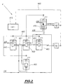
- Figure 2 shows another installation 4 made from of the kit according to the invention.
- the standard functional modules of the same set of functional modules are designated by 3-digit references, whose last two digits are identical and representative of the set to which they belong and whose first digit is equal to 1, 2 or 4 depending on the installation 1, 2 or 4 in which they are installed, or is equal to the number 3 if the functional modules are stored in the stock 3.
- the installation 1 is adapted to produce, from atmospheric air, impure nitrogen, dry air, low pressure nitrogen and nitrogen high pressure. These gases are transported to equipment consumers rated 1A, 1B, 1C and 1D respectively.
- FIG. 1 The installation of FIG. 1 comprises, at the input, a compression module standard 110. This includes 3 compressors mounted in parallel.
- the module 110 includes a local management unit, marked ULG. This is able to control the operation of the functional module for setting work of the associated elementary operation.
- the local unit ULG management system is adapted to locally manage operation of the three compressors mounted in parallel.
- Local ULG management units for all functional modules of the kit according to the invention include a communication interface, rated I / O, suitable for data transmission from and to the module corresponding functional.
- the local ULG management unit consists of a PC type computer or programmable logic controller an adapted program.
- a drying module 115 comprising 2 adsorption bottles mounted in parallel.
- the outlet of the drying module 115 supplies dry air directly consumer equipment 1B.
- a bypass supplying impure nitrogen to consumer equipment 1A are arranged in series an air treatment module 120 and a permeation module 125.
- the air treatment module 120 includes filters, while the permeation module 125 has one or more permeable membranes selectively with nitrogen and oxygen.
- the output of the drying module 115 is connected via a second bypass, to several other functional modules supplying 1C and 1D consumer equipment in low and high nitrogen pressure.
- a drying-decarbonation module 130 This comprises two mounted adsorption bottles in parallel.
- a distillation module 135 At the outlet of the dessication-decarbonation module, a distillation module 135 and a control module 140.
- the distillation module 135 has a distillation column, while the control 140 includes a set of pressure sensors.
- the output of the control module 140 is connected to the equipment consumer 1C and supplies it with low pressure nitrogen.
- the output of the control module 140 is also connected to a module overpressure 145 comprising a booster.
- the overpressure module 145 supplies 1D consumer equipment with high pressure nitrogen.
- the installation comprises a storage module 150 connected to an input of the desiccation-decarbonation module 130 for feeding the latter.
- Storage module 150 outputs are also connected, on the one hand, to the distillation module 135 and, on the other hand, to the booster module 145.
- all the functional modules of the necessary according to the invention each comprise a local management unit ULG managing the function provided by the functional module associated.
- each installation made from the necessary according to the invention, the different functional modules are connected to the same unit control center 175 specific to the installation, via a network 180.
- This network is for example of the type ETHERNET, FIP, PROFIBUS or MODBUS.
- Each functional module connected to network 180 by its I / O communication interface can thus, on the one hand, receive control orders from the central control unit 175 and, on the other hand, send it information messages relating to to its operating state.
- the operation of a given functional module is managed locally by the local management unit based only on orders received from the central control unit.
- each consumer equipment 1A, 1B, 1C, 1D is connected to the central control unit 175 by a data transfer network 185 to communicate their needs regarding the resource provided by installation.
- the central control unit 175 performs the function of "chief” by controlling the operation of each functional module installation according to the needs of consumer equipment and taking into account the information communicated by the modules functional, this information relating in particular to their availability.
- Control orders sent by the central control unit essentially contain setpoint values which must be reached at the output of the functional modules. This is for example an air flow for a compression module, a degree of humidity for a module drying, or of a minimum composition in a given constituent for a permeation or distillation module.
- Information messages sent by each functional module to the central control unit mainly contain data relating to the state of the fluid on which the functional module operates and data relating to the state or needs of the functional module.
- Data relating to the state of the fluid are divided into variables intensive, such as temperature, pressure or fluid composition and in extensive variables such as the volume or mass of the fluid treated.
- Data relating to the status or needs of the functional module relate in particular to the current operating state of the module and its future capacities to implement the operation for which it is intended. Of moreover, these data also relate to resource requirements, in particular energy, necessary for the correct functioning of the module functional.
- the standard functional modules of the same set are carried out in a standard way, so that the specifics of the inputs, outputs and I / O communication interfaces are analogous.
- the functional modules of the same set are all suitable to perform the same operation or elementary step on a fluid with a view to produce a change of state of this fluid.
- the modules are thus all interchangeable with each other due to the analogy of their entry and exit. In addition, they are likely to receive control orders from any central control unit of a installation of their local ULG management unit.
- Installation 2 shown in Figure 1 is carried out with the necessary of construction according to the invention. It is suitable for, from air atmospheric supply dry air to 2A consumer equipment and impure nitrogen in consumer equipment 2B.
- the installation 2 is made from modules standard functionalities and a central control unit from the necessary of construction.
- the installation 2 comprises, at the input, a compression module 210 mounted in series with a drying module 215.
- the output of the drying module drying 215 is connected directly to consumer equipment 2A to its dry air supply.
- a bypass ensures the routing of part of the air dry obtained at the outlet of the drying module 215 to a booster module 245.
- a module air treatment unit 220 and a permeation module 225 At the output of the latter are successively arranged a module air treatment unit 220 and a permeation module 225. The outlet from the latter is connected to the consumer equipment 2B for its power supply in impure nitrogen.
- Each of the functional modules of installation 2 is connected to a central control unit 275 via a communication network 280. This connection is made via the communication interfaces I / O of each functional module.
- the consumer equipment 2A and 2B are connected to the central unit control 275 by a data transfer network 285 allowing to consumer equipment to transmit their needs to the unit control center.
- a power module 290 is provided for power in electrical energy of each of the functional modules of the installation 2.
- This supply module 290 comprises for example a generator. It is equipped with a local ULG management unit adapted to ensure the management of the generator set.
- the local ULG management unit includes an I / O communication interface connected to the network 280.
- the module supply receives control commands from the central control unit 275 to determine its production level according to needs powered functional modules.
- Stock 3 contains different functional modules from each set. These functional modules are designated as above by a numerical reference whose first digit is 3 and whose second two numbers denote the set to which the modules belong functional.
- stock 3 includes two standard compression modules 310. These compression modules include one compressor for one and for the other a compressor.
- stock 3 has three drying modules 315, two air treatment modules 320, one permeation module 325, two modules desiccation-decarbonation 330, two distillation modules 335, two control modules 340, two booster modules 345 and two storage modules 350.
- the stock includes two central control units 375.
- Figure 2 is shown a co-generation installation of steam and electricity produced from a building kit according to the invention.
- the functional modules implemented in this installation are standard and each suitable for the implementation of an operation elementary.
- the functional modules are controlled by a central unit steering.
- the installation shown in Figure 2 is adapted to produce both electrical energy and water vapor from atmospheric air and natural gas. Electrical energy is supplied to equipment consumer 4A and water vapor is supplied to consumer equipment 4B.
- the installation 4 comprises a combustion module 455 comprising a combustion chamber whose operation is managed by the local unit ULG management specific to the functional module.
- the combustion module 455 has an inlet for introducing natural gas and an inlet for introducing an oxidizing gas formed of air compressed. These inputs supply the boiler for establishing a flame.
- the installation includes a compression module 445, receiving inlet of atmospheric air, and the outlet of which feeds the combustion module 455 in compressed air.
- the output of the combustion module 455 is connected to a detent 460 comprising a gas turbine.
- the gas turbine module trigger 460 is mechanically connected via a shaft 461 to the compressor of the compression module 445, to drive it.
- the turbine of the expansion module 460 is mechanically connected to a module for producing electrical energy 465 by a shaft 462.
- the 465 electric power production module includes an alternator driven by tree 462.
- the turbine of the expansion module 460 drives the compressor of the module compressor 445 and the generator of the power generation module electric 465.
- the output of the expansion module 460 is connected to an input of a module steam generator 470.
- the latter has a received coil in a boiler.
- the coil receives water as input and produces steam outlet.
- the boiler receives natural gas, air and combustion residues from combustion module 455, after that they have passed through the detent module 460.
- the installation 4 comprises a central control unit 475 connected by a 480 network to the I / O communication interfaces of the local units management of each of the functional modules.
- the user equipment 4A and 4B are connected to the central unit of control 475 by a 480 network to indicate to it the resource requirements output from modules 465 and 470 respectively.
- the installation is managed by the central control unit 475, which address to each of the functional modules of the order orders and receives information messages from them.
- Standardization of the inputs, outputs and interfaces of communication reduces the overall cost of production and operating several fluid treatment facilities, while satisfying the needs of consumer equipment located downstream.
- each functional module of a local unit of management ensuring the management of the module's operation from orders control received from the central control unit allows configuration quick and easy installation, only the central control unit in front be configured and programmed to meet equipment needs users.
- kit according to the invention may include functional modules for the treatment of liquids or materials powdery.
- a building kit as described here is particularly useful for gas treatment, including the separation of gases from air.
Landscapes
- Engineering & Computer Science (AREA)
- Mechanical Engineering (AREA)
- General Engineering & Computer Science (AREA)
- Combustion & Propulsion (AREA)
- Chemical & Material Sciences (AREA)
- Physics & Mathematics (AREA)
- Thermal Sciences (AREA)
- General Physics & Mathematics (AREA)
- Automation & Control Theory (AREA)
- Management, Administration, Business Operations System, And Electronic Commerce (AREA)
- Separation By Low-Temperature Treatments (AREA)
- Drying Of Gases (AREA)
- General Factory Administration (AREA)
- Feedback Control In General (AREA)
- Physical Or Chemical Processes And Apparatus (AREA)
Abstract
Description
- plusieurs ensembles, les modules fonctionnels étant aptes chacun à réaliser une opération élémentaire sur au moins un fluide d'une installation industrielle, dans lesquels :
- chaque module fonctionnel comporte au moins une entrée et au moins une sortie pour le passage d'un fluide, ainsi qu'une unité locale de gestion du module fonctionnel commandant le fonctionnement du module fonctionnel pour la mise en oeuvre de l'opération élémentaire associée, l'unité locale de gestion comportant une interface de communication,
- tous les modules fonctionnels d'un même ensemble sont adaptés pour réaliser la même opération élémentaire sur un fluide, et sont réalisés de manière standard, de sorte que les spécificités des entrées, des sorties et des interfaces de communication de tous les modules fonctionnels d'un même ensemble sont analogues, et
- les modules fonctionnels sont adaptés pour être associés fonctionnellement les uns aux autres par leurs entrées et sorties dans des installations industrielles, afin d'assurer des opérations élémentaires successives sur le fluide,
- l'unité locale de gestion de chaque module fonctionnel standard est adapté pour adresser des messages d'information à l'unité centrale de pilotage de l'installation, lesquels messages d'information sont représentatifs de l'état de fonctionnement du module fonctionnel, ou de l'état du fluide sur lequel opère le module fonctionnel ;
- l'unité centrale de pilotage de chaque installation comporte des moyens de recueil des besoins des équipements utilisateurs reliés en sortie de l'installation, au travers d'un réseau de transfert de données ;
- il comporte un ensemble de modules standards d'alimentation adaptés pour assurer l'alimentation en énergie d'une partie des modules fonctionnels de chaque installation sous la commande de l'unité de pilotage de l'installation ;
- il comporte un ensemble de modules standards de contrôle adaptés pour relever des informations sur le fluide circulant d'une installation et transmettre ces informations à l'unité centrale de pilotage de ladite installation ; et
- il comporte un ensemble de modules standards de génération d'énergie électrique adaptés pour assurer la production d'électricité à partir d'énergie fournie par d'autres modules standards de l'installation.
- chaque module fonctionnel comporte au moins une entrée et au moins une sortie pour le passage d'un fluide, ainsi qu'une unité locale de gestion du module fonctionnel commandant le fonctionnement du module fonctionnel pour la mise en oeuvre de l'opération élémentaire associée, l'unité locale de gestion comportant une interface de communication, et
- tous les modules fonctionnels d'un même ensemble sont adaptés pour réaliser la même opération élémentaire sur un fluide, et sont réalisés de manière standard, de sorte que les spécificités des entrées, des sorties et des interfaces de communication de tous les modules fonctionnels d'un même ensemble sont analogues ;
- la figure 1 est une vue schématique d'un exemple de nécessaire de construction selon l'invention, dont les modules fonctionnels sont utilisés dans deux installations industrielles ou sont disposés dans un stock ; et
- la figure 2 est une vue schématique d'une autre installation industrielle pouvant être fabriquée à l'aide du nécessaire selon l'invention.
Claims (7)
- Nécessaire de construction de plusieurs installations industrielles complexes (1, 2, 4) pour le traitement de fluides, caractérisé en ce qu'il comporte :lequel nécessaire comporte en outre, pour chaque installation industrielle (1, 2, 4), une unique unité centrale de pilotage (175, 275, 475), adaptée pour piloter l'installation industrielle associée (1, 2, 4), en adressant des ordres de pilotage aux unités locales de gestion (ULG) des modules fonctionnels standards de l'installation industrielle, au travers des interfaces de communication (E/S) reliées à l'unité centrale de pilotage (175, 275, 475) par un réseau de communication (180, 280, 480).plusieurs ensembles (10, 15, 20, 25, 30, 35, 45, 50, 55, 60, 65, 70) de plusieurs modules fonctionnels (110, 115, 120, 125, 130, 135, 145, 150, 210, 215, 220, 225, 230, 235, 245, 250, 310, 315, 320, 325, 330, 335, 345, 350, 445, 455, 460, 465, 470), les modules fonctionnels étant aptes chacun à réaliser une opération physique élémentaire sur au moins un fluide d'une installation industrielle, dans lesquels :chaque module fonctionnel comporte au moins une entrée et au moins une sortie pour le passage d'un fluide, ainsi qu'une unité locale de gestion (ULG) du module fonctionnel commandant le fonctionnement du module fonctionnel pour la mise en oeuvre de l'opération élémentaire associée, l'unité locale de gestion (ULG) comportant une interface de communication (E/S),tous les modules fonctionnels d'un même ensemble (10, 15, 20, 25, 30, 35, 45, 50, 55, 60, 65, 70) sont adaptés pour réaliser la même opération élémentaire sur un fluide, et sont réalisés de manière standard, de sorte que les spécificités des entrées, des sorties et des interfaces de communication (E/S) de tous les modules fonctionnels d'un même ensemble sont analogues, etles modules fonctionnels sont adaptés pour être associés fonctionnellement les uns aux autres par leurs entrées et sorties dans des installations industrielles, afin d'assurer des opérations élémentaires successives sur le fluide,
- Nécessaire selon la revendication 1, caractérisé en ce que l'unité locale de gestion (ULG) de chaque module fonctionnel standard est adaptée pour adresser à l'unité centrale de pilotage (175, 275, 475) de l'installation, des messages d'information représentatifs de l'état de fonctionnement du module fonctionnel, ou de l'état du fluide sur lequel opère le module fonctionnel.
- Nécessaire selon la revendication 1 ou 2, caractérisé en ce que l'unité centrale de pilotage (175, 275, 475) de chaque installation (1, 2, 4) comporte des moyens de recueil des besoins des équipements utilisateurs (1A, 1B, 1C, 1D, 2A, 2B, 4A, 4B) reliés en sortie de l'installation, au travers d'un réseau de transfert de données (185, 285, 485).
- Nécessaire selon l'une quelconque des revendications précédentes, caractérisé en ce qu'il comporte un ensemble de modules standards d'alimentation (290) adaptés pour assurer l'alimentation en énergie d'une partie des modules fonctionnels de chaque installation sous la commande de l'unité de pilotage (275) de l'installation.
- Nécessaire selon l'une quelconque des revendications précédentes, caractérisé en ce qu'il comporte un ensemble de modules standards de contrôle (140, 340) adaptés pour relever des informations sur le fluide circulant d'une installation et transmettre ces informations à l'unité centrale de pilotage (175) de ladite installation.
- Nécessaire selon l'une quelconque des revendications précédentes, caractérisé en ce qu'il comporte un ensemble de modules standards de génération d'énergie électrique (465) adaptés pour assurer la production d'électricité à partir d'énergie fournie par d'autres modules standards (460) de l'installation.
- Procédé de construction de plusieurs installations industrielles complexes (1, 2, 4) pour le traitement de fluides, caractérisé en ce qu'il comporte les étapes consistant à :A) fabriquer des ensembles (10, 15, 20, 25, 30, 35, 45, 50, 55, 60, 65, 70) de plusieurs modules fonctionnels (110, 115, 120, 125, 130, 135, 145, 150, 210, 215, 220, 225, 230, 235, 245, 250, 310, 315, 320, 325, 330, 335, 345, 350, 445, 455, 460, 465, 470), les modules fonctionnels étant aptes chacun à réaliser une opération physique élémentaire d'une installation industrielle, dans lesquels :chaque module fonctionnel comporte au moins une entrée et au moins une sortie pour le passage d'un fluide, ainsi qu'une unité locale de gestion (ULG) du module fonctionnel commandant le fonctionnement du module fonctionnel pour la mise en oeuvre de l'opération élémentaire associée, l'unité locale de gestion (ULG) comportant une interface de communication (E/S), ettous les modules fonctionnels d'un même ensemble (10, 15, 20, 25, 30, 35, 45, 50, 55, 60, 65, 70) sont adaptés pour réaliser la même opération élémentaire sur un fluide, et sont réalisés de manière standard, de sorte que les spécificités des entrées, des sorties et des interfaces de communication (E/S) de tous les modules fonctionnels d'un même ensemble sont analogues ;B) fabriquer pour chaque installation industrielle, une unité centrale de pilotage (175, 275, 475) adaptée pour piloter l'installation industrielle associée, en adressant des ordres de pilotage aux unités locales de gestion (ULG) de chaque module fonctionnel standard de l'installation, au travers des interfaces de communication (E/S) reliées à l'unité centrale de pilotage (175, 275, 475) par un réseau de communication (180, 280, 480) ;C) associer fonctionnellement, dans chaque installation industrielle (1, 2, 4), les modules fonctionnels les uns aux autres par leurs entrées et sorties, afin d'assurer les opérations élémentaires successives sur le fluide de chaque installation industrielle complexe ; etD) installer dans chaque installation industrielle (1, 2, 4) une unité centrale de pilotage (175, 275, 475) reliée aux interfaces de communication (E/S) de tous les modules fonctionnels standards de l'installation par un réseau de communication (180, 280, 480).
Applications Claiming Priority (2)
| Application Number | Priority Date | Filing Date | Title |
|---|---|---|---|
| FR9906089 | 1999-05-12 | ||
| FR9906089A FR2793424B1 (fr) | 1999-05-12 | 1999-05-12 | Necessaire et procede de construction de plusieurs installations industrielles complexes |
Publications (2)
| Publication Number | Publication Date |
|---|---|
| EP1052559A1 true EP1052559A1 (fr) | 2000-11-15 |
| EP1052559B1 EP1052559B1 (fr) | 2006-08-02 |
Family
ID=9545541
Family Applications (1)
| Application Number | Title | Priority Date | Filing Date |
|---|---|---|---|
| EP00401092A Expired - Lifetime EP1052559B1 (fr) | 1999-05-12 | 2000-04-19 | Nécessaire et procédé de construction de plusieurs installations industrielles complexes |
Country Status (8)
| Country | Link |
|---|---|
| US (1) | US6865448B1 (fr) |
| EP (1) | EP1052559B1 (fr) |
| AU (1) | AU4126200A (fr) |
| DE (1) | DE60029674T2 (fr) |
| ES (1) | ES2269074T3 (fr) |
| FR (1) | FR2793424B1 (fr) |
| WO (1) | WO2000070418A1 (fr) |
| ZA (1) | ZA200002158B (fr) |
Cited By (3)
| Publication number | Priority date | Publication date | Assignee | Title |
|---|---|---|---|---|
| WO2002042712A1 (fr) * | 2000-11-24 | 2002-05-30 | Siemens Aktiengesellschaft | Systeme modulaire permettant d'etablir une installation industrielle |
| FR2837530A1 (fr) * | 2002-03-21 | 2003-09-26 | Mdi Motor Dev Internat | Groupe de cogeneration individuel et reseau de proximite |
| US7003359B2 (en) | 2001-08-17 | 2006-02-21 | Air Products And Chemicals, Inc. | Multiple process plant product lines from a common set of engineered components |
Families Citing this family (4)
| Publication number | Priority date | Publication date | Assignee | Title |
|---|---|---|---|---|
| US20070094946A1 (en) * | 2005-09-30 | 2007-05-03 | Ohio Transmission Corporation | Modular industrial equipment facility |
| EP2746762B1 (fr) * | 2012-12-21 | 2020-01-22 | Sick Ag | Capteur de surveillance de tunnel |
| CN116300587A (zh) * | 2023-02-20 | 2023-06-23 | 广东金朋科技有限公司 | 硬件模块化处理方法、装置、电子设备和存储介质 |
| CN116931518A (zh) * | 2023-07-10 | 2023-10-24 | 三一重型装备有限公司 | 控制系统的开发方法、工业设备的控制方法、装置和介质 |
Citations (5)
| Publication number | Priority date | Publication date | Assignee | Title |
|---|---|---|---|---|
| GB2197910A (en) * | 1986-11-27 | 1988-06-02 | Orian Emilia | Modular gas turbine plant |
| US4802100A (en) * | 1986-08-18 | 1989-01-31 | Gas Research Institute | Advanced cogeneration control system |
| US5496388A (en) * | 1994-07-01 | 1996-03-05 | Air Liquide America Corporation | System for compressing air and extracting nitrogen from compressed air |
| FR2770287A1 (fr) * | 1997-10-27 | 1999-04-30 | Esys Montenay | Dispositif de gestion automatisee de consommation d'energie |
| FR2785062A1 (fr) * | 1998-10-26 | 2000-04-28 | Air Liquide | Installation et procede de production comportant plusieurs etapes de traitement |
Family Cites Families (3)
| Publication number | Priority date | Publication date | Assignee | Title |
|---|---|---|---|---|
| US3649208A (en) * | 1969-09-25 | 1972-03-14 | Ingersoll Rand Co | Fluid compressor system |
| FR2638910B1 (fr) * | 1988-09-28 | 1991-04-26 | Boussard Alain | Alimentation electrique pour salles d'informatique |
| AU4915397A (en) * | 1996-10-18 | 1998-05-15 | Westinghouse Savannah River Company | Programmable atmospheric sampling systems and methods |
-
1999
- 1999-05-12 FR FR9906089A patent/FR2793424B1/fr not_active Expired - Fee Related
-
2000
- 2000-04-19 DE DE60029674T patent/DE60029674T2/de not_active Expired - Lifetime
- 2000-04-19 ES ES00401092T patent/ES2269074T3/es not_active Expired - Lifetime
- 2000-04-19 US US09/743,200 patent/US6865448B1/en not_active Expired - Fee Related
- 2000-04-19 WO PCT/FR2000/001016 patent/WO2000070418A1/fr not_active Ceased
- 2000-04-19 EP EP00401092A patent/EP1052559B1/fr not_active Expired - Lifetime
- 2000-04-19 AU AU41262/00A patent/AU4126200A/en not_active Abandoned
- 2000-05-03 ZA ZA200002158A patent/ZA200002158B/xx unknown
Patent Citations (5)
| Publication number | Priority date | Publication date | Assignee | Title |
|---|---|---|---|---|
| US4802100A (en) * | 1986-08-18 | 1989-01-31 | Gas Research Institute | Advanced cogeneration control system |
| GB2197910A (en) * | 1986-11-27 | 1988-06-02 | Orian Emilia | Modular gas turbine plant |
| US5496388A (en) * | 1994-07-01 | 1996-03-05 | Air Liquide America Corporation | System for compressing air and extracting nitrogen from compressed air |
| FR2770287A1 (fr) * | 1997-10-27 | 1999-04-30 | Esys Montenay | Dispositif de gestion automatisee de consommation d'energie |
| FR2785062A1 (fr) * | 1998-10-26 | 2000-04-28 | Air Liquide | Installation et procede de production comportant plusieurs etapes de traitement |
Non-Patent Citations (4)
| Title |
|---|
| "CATALOGO GENERAL DE EQUIPOS Y SISTEMAS. VERSION E-09.94, TOMO II", September 1994, STAEFA CONTROL SYSTEMS, SPAIN, XP002131836 * |
| "INSTRUPEDIA 97. YOUR INTERACTIVE ENCYCLOPEDIA FOR INSTRUMENTATION", 1997, NATIONAL INSTRUMENTS CORPORATION, U.S.A., XP002131837 * |
| FISHER-ROSEMOUNT: "INTEGRATED SUITES FOR BUILDING COMPETITIVE ADVANTAGE", PLANTWEB BUILDER, 1998, USA, XP002144951 * |
| MESA A A ET AL: "Design of the maximum energy efficiency desalination plant (PAME)", DESALINATION,NL,ELSEVIER SCIENTIFIC PUBLISHING CO, AMSTERDAM, vol. 108, no. 1, 1 February 1997 (1997-02-01), pages 111 - 116, XP004053166, ISSN: 0011-9164 * |
Cited By (5)
| Publication number | Priority date | Publication date | Assignee | Title |
|---|---|---|---|---|
| WO2002042712A1 (fr) * | 2000-11-24 | 2002-05-30 | Siemens Aktiengesellschaft | Systeme modulaire permettant d'etablir une installation industrielle |
| US7003359B2 (en) | 2001-08-17 | 2006-02-21 | Air Products And Chemicals, Inc. | Multiple process plant product lines from a common set of engineered components |
| FR2837530A1 (fr) * | 2002-03-21 | 2003-09-26 | Mdi Motor Dev Internat | Groupe de cogeneration individuel et reseau de proximite |
| WO2003081012A1 (fr) * | 2002-03-21 | 2003-10-02 | Mdi Motor Developement International S.A. | Groupe de cogeneration individuel et reseau de proximite |
| US7124586B2 (en) | 2002-03-21 | 2006-10-24 | Mdi Motor Development International S.A. | Individual cogeneration plant and local network |
Also Published As
| Publication number | Publication date |
|---|---|
| EP1052559B1 (fr) | 2006-08-02 |
| ZA200002158B (en) | 2000-11-07 |
| DE60029674T2 (de) | 2007-10-04 |
| ES2269074T3 (es) | 2007-04-01 |
| WO2000070418A1 (fr) | 2000-11-23 |
| US6865448B1 (en) | 2005-03-08 |
| FR2793424A1 (fr) | 2000-11-17 |
| FR2793424B1 (fr) | 2001-07-13 |
| AU4126200A (en) | 2000-12-05 |
| DE60029674D1 (de) | 2006-09-14 |
Similar Documents
| Publication | Publication Date | Title |
|---|---|---|
| AU660790B2 (en) | Real-time economic load allocation | |
| EP1052559B1 (fr) | Nécessaire et procédé de construction de plusieurs installations industrielles complexes | |
| JP5575373B2 (ja) | 複合ガスタービンプラントの出力差異及び保守の容易化のための方法及びシステム | |
| CN101681398B (zh) | 组装及操作电子器件制造系统的方法和设备 | |
| CN101163642B (zh) | 用于对组合式发电和水脱盐设备进行使用规划、工艺监控、仿真和优化的系统和方法 | |
| CA3122184A1 (fr) | Optimisation energetique et environnementale d'une installation comprenant au moins un appareil a combustion a bruleur | |
| CA2875468A1 (fr) | Procede de regulation d'une installation comprenant des appareils de cogeneration et des systemes thermodynamiques destines a la climatisation et/ou au chauffage | |
| CA2136659A1 (fr) | Procede et installation de fourniture d'azote au moyen de membranes semi-permeables utilisant une geometrie membranaire variable | |
| FR2964204A1 (fr) | Procede de determination de parametres de regulation d'un systeme hvac | |
| WO2003044350A1 (fr) | Systeme de machine de sechage avec turbine a gaz et methode d'utilisation | |
| JP2020531597A (ja) | 様々な構成が可能なバイオマス燃料のポリジェネレーション・プラント | |
| EP1511965B1 (fr) | Procede et installation de pilotage d au moins un compresseu r centrifuge cryogenique, ligne de compression | |
| WO2020216881A1 (fr) | Systeme et methode de distribution d'energie electrique | |
| CA3103749A1 (fr) | Installation de rebours mobile | |
| EP1521628B1 (fr) | Procede de conduite d'une installation de production | |
| FR2985006A1 (fr) | Procede de production d'un systeme pour la realisation d'un procede de separation d'air, procede de production d'un appareil de separation d'air et installation de separation d'air par distillation cryogenique | |
| CN222509446U (zh) | 一种高炉鼓风数据传输系统 | |
| EP0803581B1 (fr) | Procédé d'élaboration d'une atmosphère de traitement thermique et méthode de régulation d'un tel procédé | |
| US5404314A (en) | Real time environmental load allocation | |
| Münch et al. | Stationary fuel cells—Results of 2 years of operation at EnBW | |
| EP2795215A1 (fr) | Procede et appareil de separation d'air par distillation cryogenique | |
| TW202040002A (zh) | 真空泵送 | |
| JP2001193914A (ja) | プラズマcvd装置からの可燃性廃ガスの燃焼処理方法とそのためのシステム | |
| EP0610908B1 (fr) | Procédé d'installation d'une nouvelle fonction de commande pour appareils électriques | |
| Pithoud et al. | D4. 3 Report on the control system design |
Legal Events
| Date | Code | Title | Description |
|---|---|---|---|
| PUAI | Public reference made under article 153(3) epc to a published international application that has entered the european phase |
Free format text: ORIGINAL CODE: 0009012 |
|
| AK | Designated contracting states |
Kind code of ref document: A1 Designated state(s): DE ES FR GB IT NL |
|
| AX | Request for extension of the european patent |
Free format text: AL;LT;LV;MK;RO;SI |
|
| RIN1 | Information on inventor provided before grant (corrected) |
Inventor name: ROTMAN, FREDERIC Inventor name: FERENCZI, LAURENT Inventor name: WILLEMOT, ANTOINE Inventor name: BARRY, LIONEL |
|
| 17P | Request for examination filed |
Effective date: 20010515 |
|
| AKX | Designation fees paid |
Free format text: DE ES FR GB IT NL |
|
| RAP1 | Party data changed (applicant data changed or rights of an application transferred) |
Owner name: L'AIR LIQUIDE, S.A. A DIRECTOIRE ET CONSEIL DE SUR |
|
| 17Q | First examination report despatched |
Effective date: 20050324 |
|
| GRAP | Despatch of communication of intention to grant a patent |
Free format text: ORIGINAL CODE: EPIDOSNIGR1 |
|
| GRAS | Grant fee paid |
Free format text: ORIGINAL CODE: EPIDOSNIGR3 |
|
| GRAA | (expected) grant |
Free format text: ORIGINAL CODE: 0009210 |
|
| AK | Designated contracting states |
Kind code of ref document: B1 Designated state(s): DE ES FR GB IT NL |
|
| PG25 | Lapsed in a contracting state [announced via postgrant information from national office to epo] |
Ref country code: IT Free format text: LAPSE BECAUSE OF FAILURE TO SUBMIT A TRANSLATION OF THE DESCRIPTION OR TO PAY THE FEE WITHIN THE PRESCRIBED TIME-LIMIT;WARNING: LAPSES OF ITALIAN PATENTS WITH EFFECTIVE DATE BEFORE 2007 MAY HAVE OCCURRED AT ANY TIME BEFORE 2007. THE CORRECT EFFECTIVE DATE MAY BE DIFFERENT FROM THE ONE RECORDED. Effective date: 20060802 |
|
| REG | Reference to a national code |
Ref country code: GB Ref legal event code: FG4D Free format text: NOT ENGLISH |
|
| REF | Corresponds to: |
Ref document number: 60029674 Country of ref document: DE Date of ref document: 20060914 Kind code of ref document: P |
|
| GBT | Gb: translation of ep patent filed (gb section 77(6)(a)/1977) |
Effective date: 20061108 |
|
| REG | Reference to a national code |
Ref country code: ES Ref legal event code: FG2A Ref document number: 2269074 Country of ref document: ES Kind code of ref document: T3 |
|
| RAP2 | Party data changed (patent owner data changed or rights of a patent transferred) |
Owner name: L'AIR LIQUIDE, SOCIETE ANONYME POUR L'ETUDE ET L'E |
|
| PLBE | No opposition filed within time limit |
Free format text: ORIGINAL CODE: 0009261 |
|
| STAA | Information on the status of an ep patent application or granted ep patent |
Free format text: STATUS: NO OPPOSITION FILED WITHIN TIME LIMIT |
|
| RAP2 | Party data changed (patent owner data changed or rights of a patent transferred) |
Owner name: L'AIR LIQUIDE, SOCIETE ANONYME POUR L'ETUDE ET L'E |
|
| NLT2 | Nl: modifications (of names), taken from the european patent patent bulletin |
Owner name: L'AIR LIQUIDE, SOCIETE ANONYME POUR L'ETUDE Effective date: 20070425 |
|
| 26N | No opposition filed |
Effective date: 20070503 |
|
| NLT2 | Nl: modifications (of names), taken from the european patent patent bulletin |
Owner name: L'AIR LIQUIDE, SOCIETE ANONYME POUR L'ETUDE Effective date: 20070627 |
|
| PGFP | Annual fee paid to national office [announced via postgrant information from national office to epo] |
Ref country code: ES Payment date: 20120424 Year of fee payment: 13 |
|
| PGFP | Annual fee paid to national office [announced via postgrant information from national office to epo] |
Ref country code: GB Payment date: 20130418 Year of fee payment: 14 Ref country code: DE Payment date: 20130419 Year of fee payment: 14 |
|
| PGFP | Annual fee paid to national office [announced via postgrant information from national office to epo] |
Ref country code: NL Payment date: 20130418 Year of fee payment: 14 Ref country code: IT Payment date: 20130423 Year of fee payment: 14 Ref country code: FR Payment date: 20130515 Year of fee payment: 14 |
|
| REG | Reference to a national code |
Ref country code: DE Ref legal event code: R119 Ref document number: 60029674 Country of ref document: DE |
|
| REG | Reference to a national code |
Ref country code: NL Ref legal event code: V1 Effective date: 20141101 |
|
| GBPC | Gb: european patent ceased through non-payment of renewal fee |
Effective date: 20140419 |
|
| REG | Reference to a national code |
Ref country code: FR Ref legal event code: ST Effective date: 20141231 |
|
| REG | Reference to a national code |
Ref country code: DE Ref legal event code: R119 Ref document number: 60029674 Country of ref document: DE Effective date: 20141101 |
|
| PG25 | Lapsed in a contracting state [announced via postgrant information from national office to epo] |
Ref country code: GB Free format text: LAPSE BECAUSE OF NON-PAYMENT OF DUE FEES Effective date: 20140419 Ref country code: DE Free format text: LAPSE BECAUSE OF NON-PAYMENT OF DUE FEES Effective date: 20141101 |
|
| PG25 | Lapsed in a contracting state [announced via postgrant information from national office to epo] |
Ref country code: NL Free format text: LAPSE BECAUSE OF NON-PAYMENT OF DUE FEES Effective date: 20141101 Ref country code: FR Free format text: LAPSE BECAUSE OF NON-PAYMENT OF DUE FEES Effective date: 20140430 |
|
| PG25 | Lapsed in a contracting state [announced via postgrant information from national office to epo] |
Ref country code: IT Free format text: LAPSE BECAUSE OF NON-PAYMENT OF DUE FEES Effective date: 20140419 |
|
| REG | Reference to a national code |
Ref country code: ES Ref legal event code: FD2A Effective date: 20150526 |
|
| PG25 | Lapsed in a contracting state [announced via postgrant information from national office to epo] |
Ref country code: ES Free format text: LAPSE BECAUSE OF NON-PAYMENT OF DUE FEES Effective date: 20140420 |