EP1052437B1 - Brush seal segment having bristle damping - Google Patents
Brush seal segment having bristle damping Download PDFInfo
- Publication number
- EP1052437B1 EP1052437B1 EP00303946A EP00303946A EP1052437B1 EP 1052437 B1 EP1052437 B1 EP 1052437B1 EP 00303946 A EP00303946 A EP 00303946A EP 00303946 A EP00303946 A EP 00303946A EP 1052437 B1 EP1052437 B1 EP 1052437B1
- Authority
- EP
- European Patent Office
- Prior art keywords
- front plate
- bristles
- holes
- brush seal
- brush
- Prior art date
- Legal status (The legal status is an assumption and is not a legal conclusion. Google has not performed a legal analysis and makes no representation as to the accuracy of the status listed.)
- Expired - Lifetime
Links
- 238000013016 damping Methods 0.000 title 1
- 230000014509 gene expression Effects 0.000 description 8
- 238000009434 installation Methods 0.000 description 4
- 238000012423 maintenance Methods 0.000 description 4
- 238000010276 construction Methods 0.000 description 3
- 238000011144 upstream manufacturing Methods 0.000 description 3
- 239000000446 fuel Substances 0.000 description 2
- 229910000531 Co alloy Inorganic materials 0.000 description 1
- -1 but not limited to Inorganic materials 0.000 description 1
- 239000002184 metal Substances 0.000 description 1
- 229910052751 metal Inorganic materials 0.000 description 1
- 229910001092 metal group alloy Inorganic materials 0.000 description 1
- 230000002028 premature Effects 0.000 description 1
- 238000010926 purge Methods 0.000 description 1
- 239000010935 stainless steel Substances 0.000 description 1
- 229910001220 stainless steel Inorganic materials 0.000 description 1
- 230000001052 transient effect Effects 0.000 description 1
- 238000003466 welding Methods 0.000 description 1
Images

Classifications
-
- F—MECHANICAL ENGINEERING; LIGHTING; HEATING; WEAPONS; BLASTING
- F16—ENGINEERING ELEMENTS AND UNITS; GENERAL MEASURES FOR PRODUCING AND MAINTAINING EFFECTIVE FUNCTIONING OF MACHINES OR INSTALLATIONS; THERMAL INSULATION IN GENERAL
- F16J—PISTONS; CYLINDERS; SEALINGS
- F16J15/00—Sealings
- F16J15/16—Sealings between relatively-moving surfaces
- F16J15/32—Sealings between relatively-moving surfaces with elastic sealings, e.g. O-rings
- F16J15/3284—Sealings between relatively-moving surfaces with elastic sealings, e.g. O-rings characterised by their structure; Selection of materials
- F16J15/3288—Filamentary structures, e.g. brush seals
Definitions
- the present invention relates generally to seals, and more particularly to a brush seal segment.
- Rotary machines include, without limitation, turbines for steam turbines and compressors and turbines for gas turbines.
- a steam turbine has a steam path which typically includes, in serial-flow relationship, a steam inlet, a turbine, and a steam outlet.
- a gas turbine has a gas path which typically includes, in serial-flow relationship, an air intake (or inlet), a compressor, a combustor, a turbine, and a gas outlet (or exhaust nozzle). Gas or steam leakage, either out of the gas or steam path or into the gas or steam path, from an area of higher pressure to an area of lower pressure, is generally undesirable.
- gas-path leakage in the turbine or compressor area of a gas turbine, between the rotor of the turbine or compressor and the circumferentially surrounding turbine or compressor casing will lower the efficiency of the gas turbine leading to increased fuel costs.
- steam-path leakage in the turbine area of a steam turbine, between the rotor of the turbine and the circumferentially surrounding casing will lower the efficiency of the steam turbine leading to increased fuel costs.
- Annular brush seals have been proposed for use between a rotor and a surrounding casing in gas and steam turbines.
- the annular brush seal is made up of circumferentially-arrayed brush seal segments.
- Each brush seal segment is attached to the casing and includes a back (i.e., downstream) plate, a front (i.e., upstream) plate, and bristles which are positioned between the back and front plates with the free end of generally each bristle extending beyond the edges of the back and front plates.
- the bristles typically are canted at an angle of generally forty-five degrees in the direction of rotation of the rotor, and the free ends of the bristles are close to (and may even touch) the rotor.
- the front plate (and in some designs also portions of the back plate), near the free ends of the bristles, is spaced apart from the bristles to allow room for the bristles to flex and recover during transient encounters of the free ends of the bristles with the rotor.
- the upstream gas flow is turbulent, some of the flow can swirl between the front plate and the bristles causing bristle flutter (i.e., instability) which quickly wears the bristles leading to premature brush seal failure.
- bristle flutter i.e., instability
- GB-A-2258277 shows a brush seal with holes which direct flow into a channel between a support plate and a shield plate to maintain the bristles in optimum position.
- US-A-5752805 shows a brush seal which utilizes a pressure differential to maintain bristle position.
- a brush seal segment comprising a) a brush-seal back plate having an edge; b) a brush-seal front plate having an edge ; and c) a plurality of brush-seal bristles each having a free end, wherein said bristles are disposed between said back and front plates with said free end of generally each bristle extending beyond said edges of said back and front plates, wherein said front plate has a portion extending to said edge of said front plate with said portion being spaced apart from said bristles; wherein said portion of said front plate has an array of through holes, and wherein said through holes include first holes each having a length which is greater than the distance from said portion of said front plate to said bristles characterised by second different holes being generally aligned in the direction towards the free ends of the bristles such that a gas subflow exiting the second holes is directed to impact the free ends of the bristles in the absence of other flow.
- the through holes in the front plate allow a subflow to pass therethrough and purge the space between the front plate and the bristles of turbulent flow otherwise entering the space near the free ends of the bristles such that the free ends of the bristles are damped since they experience a more stable flow resulting in less bristle flutter and hence increased brush-seal wear.
- the upstream-extending ledge of the front plate acts to channelize the turbulent flow such that the free ends of the bristles are damped since they experience a more stable flow resulting in less bristle flutter and hence increased brush-seal wear.
- Figure 1 schematically shows an embodiment of the brush seal segment 10 of the present invention together with five other identical brush seal segments 12, 14, 16, 18, and 20 all circumferentially arrayed to define an annular brush seal 22.
- Figure 2 shows one of the brush seal segments 10 installed in an embodiment of a gas turbine assembly 24 (only a portion of which is shown in Figure 2), such gas turbine assembly 24 having a rotor 26 and a casing 28 radially spaced apart from and circumferentially surrounding the rotor 26, such brush seal segment 10 disposed in the annular gap between the rotor 26 and the casing 28, and such brush seal segment 10 attached to the casing 28.
- the brush seal segment 10 could be disposed in any other rotary machine including, without limitation, a steam turbine.
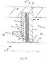
- a brush seal segment 10 includes a brush-seal back plate 30 having an edge 32, a brush-seal front plate 34 having an edge 36, and a plurality of brush-seal bristles 38 each having a free end 40.
- the bristles 38 are disposed between the back and front plates 30 and 34 with the free end 40 of generally each bristle 38 extending beyond the edges 32 and 36 of the back and front plates 30 and 34.
- the front plate 34 has a portion 42 extending to the edge 36 of the front plate 34 with the portion 42 spaced apart from the bristles 38.
- the portion 42 of the front plate 34 has an array of through holes 44 and 46.
- the brush seal segment 10 has only one front plate 34, and, in another design, the front plate 34 is a manually-rigid front plate 34.
- the front plate 34 is a manually-rigid front plate 34.
- the through holes 44 and 46 include first holes 44 each having a length which is greater than the distance from the portion 42 of the front plate 34 to the bristles 38.
- a longer first hole 44 will channelize a gas subflow, and a shorter exit distance to the bristles 38 will improve the control of the directed impact of the channelized gas subflow from the first holes 44 against the bristles 38.
- the bristles 38 closest to the portion 42 of the front plate 34 generally lie in a plane.
- the first holes 44 are aligned generally perpendicular to the plane.
- the first holes 44 are all of the through holes 44 and 46 which are visible in a drawing of a front (i.e., downstream-facing) view of the brush seal segment 10 (such as in Figure 1).
- a brush seal segment 10 includes a brush-seal holder 48 having a shape of generally an annular segment of a circular ring, wherein the ring has a longitudinal axis 50.
- the brush-seal holder 48 has an annular brush-seal back plate 30 and an annular brush-seal front plate 34 each generally coaxially aligned with the axis 50 and each having an inner circumferential edge 32 and 36 generally facing the axis 50.
- the brush seal segment 10 also includes a plurality of brush-seal bristles 38 each having a free end 40.
- the bristles 38 are disposed longitudinally between the back and front plates 30 and 34 with the free end 40 of generally each bristle 38 extending beyond the edges 32 and 36 of the back and front plates 30 and 34.
- the edge 32 of the back plate 30 extends closer to the axis 50 than does the edge 36 of the front plate 34.
- the front plate 34 has a portion 42 extending to the edge 36 of the front plate 34 with the portion 42 longitudinally spaced apart from the bristles 38.
- the portion 42 of the front plate 34 has an array of through holes 44 and 46.
- the brush seal segment 10 has only one front plate 34, and, in another design, the front plate 34 is a manually-rigid front plate 34.
- a single, rigid front plate is less prone to unwanted flutter in a turbulent gas flow and is less susceptible to damage during shipping and installation and during maintenance of nearby turbine components.
- the through holes 44 and 46 include first holes 44 each having a length which is greater than the distance from the portion 42 of the front plate 34 to the bristles 38. A longer first hole 44 will channelize a gas subflow, and a shorter exit distance to the bristles 38 will improve the control of the directed impact of the channelized gas subflow from the first holes 44 against the bristles 38.
- the first holes 44 are aligned generally parallel to the axis 50.
- the first holes 44 are all of the through holes 44 and 46 which are visible in a drawing of a front (i.e., downstream-facing) view of the brush seal segment 10 (such as in Figure 1).
- a brush seal segment 10 includes a brush-seal back plate 30 having an edge 32, a brush-seal front plate 34 having an edge 36, and a plurality of brush-seal bristles 38 each having a free end 40.
- the bristles 38 are disposed between the back and front plates 30 and 34 with the free end 40 of generally each bristle 38 extending beyond the edges 32 and 36 of the back and front plates 30 and 34.
- the front plate 34 has a portion 42 extending to the edge 36 of the front plate 34 with the portion 42 spaced apart from the bristles 38.
- the portion 42 of the front plate 34 at the edge 36 of the front plate 34 has a ledge 52 projecting generally away from the bristles 38.
- the brush seal segment 10 has only one front plate 34, and, in another design, the front plate 34 is a manually-rigid front plate 34.
- a single, rigid front plate is less prone to unwanted flutter in a turbulent gas flow and is less susceptible to damage during shipping and installation and during maintenance of nearby turbine components.
- the bristles 38 closest to the portion 42 of the front plate 34 generally lie in a plane
- the portion 42 of the front plate 34 has a thickness along a direction perpendicular to the plane
- the thickness of the ledge 52 of the portion 42 of the front plate 34 is greater than twice the thickness of any other part of the portion 42 of the front plate 34.
- the portion 42 of the front plate 34 has an array of through holes 44 and 46, with the portion 42 apart from the ledge 52 containing an array of first holes 44 (as otherwise previously described in the first and second expressions of the embodiment of the invention shown in the figures), and with the ledge 52 of the portion 42 containing an array of second holes 46.
- the second holes 46 each are generally aligned such that a gas subflow exiting the second holes 46 is directed to impact the free ends 40 of the bristles 38 in the absence of any other flow.
- the second holes 46 are the only through holes 44 and 46 which are visible in a drawing (not shown) of a radially-inward view, and in a drawing (not shown) of a radially-outward view, of the brush seal segment 10.
- the aligned second holes 46 help keep unwanted turbulent flow from entering the space between the front plate 34 and the bristles 38 reducing unwanted bristle flutter.
- a brush seal segment 10 includes a brush-seal holder 48 having a shape of generally an annular segment of a circular ring, wherein the ring has a longitudinal axis 50.
- the brush-seal holder 48 has an annular brush-seal back plate 30 and an annular brush-seal front plate 34 each generally coaxially aligned with the axis 50 and each having an inner circumferential edge 32 and 36 generally facing the axis 50.
- the brush seal segment 10 also includes a plurality of brush-seal bristles 38 each having a free end 40.
- the bristles 38 are disposed longitudinally between the back and front plates 30 and 34 with the free end 40 of generally each bristle 38 extending beyond the edges 32 and 36 of the back and front plates 30 and 34.
- the edge 32 of the back plate 30 extends closer to the axis 50 than does the edge 36 of the front plate 34.
- the front plate 34 has a portion 42 extending to the edge 36 of the front plate 34 with the portion 42 longitudinally spaced apart from the bristles 38.
- the portion 42 of the front plate 34 at the edge 36 of the front plate 34 has a ledge 52 projecting generally longitudinally away from the bristles 38.
- the brush seal segment 10 has only one front plate 34, and, in another design, the front plate 34 is a manually-rigid front plate 34.
- a single, rigid front plate is less prone to unwanted flutter in a turbulent gas flow and is less susceptible to damage during shipping and installation and during maintenance of nearby turbine components.
- the bristles 38 closest to the portion 42 of the front plate 34 generally lie in a plane
- the portion 42 of the front plate 34 has a thickness along a direction perpendicular to the plane (i.e., parallel to the axis 50)
- the thickness of the ledge 52 of the portion 42 of the front plate 34 is greater than twice the thickness of any other part of the portion 42 of the front plate 34.
- the portion 42 of the front plate 34 has an array of through holes 44 and 46, with the portion 42 apart from the ledge 52 containing an array of first holes 44 (as otherwise previously described in the first and second expressions of the embodiment of the invention shown in the figures), and with the ledge 52 of the portion 42 containing an array of second holes 46.
- the second holes 46 each are generally aligned such that a gas subflow exiting the second holes 46 is directed to impact the free ends 40 of the bristles 38 in the absence of any other flow.
- the second holes 46 are the only through holes 44 and 46 which are visible in a drawing (not shown) of a radially-inward view, and in a drawing (not shown) of a radially-outward view, of the brush seal segment 10.
- the aligned second holes 46 help keep unwanted turbulent flow from entering the space between the front plate 34 and the bristles 38 reducing unwanted bristle flutter.
- the bristles 38 are each canted at a generally-identical angle with respect to a corresponding radius line (not shown) extending outward (from the axis 50) to each of the bristles 38.
- the angle of the bristles 38 is generally forty-five degrees.
- the back plate 30 and the front plate 34 each are of monolithic construction and consist essentially of metal or metal alloy such as, but not limited to, stainless steel.
- the bristles 38 typically consist essentially of metal-wire or ceramic-wire bristles such as, but not limited to, cobalt-based-alloy wire bristles.
- metal-wire bristles 38 are attached to the brush-seal holder 48 by welding (such weldment omitted from the figures for clarity).
- the brush seal segment 10 has a high-pressure side 54 and a low-pressure side 56, with the radially-outward part of the brush-seal holder 48 attached to the casing 28 (such as by engagement of the brush seal segment 10 with a slot 58 in the casing 28), and with the inwardly-projecting free ends 40 (as seen in the view of Figure 2) of the bristles 38 disposed proximate (and in one application disposed as to just touch) the rotor 26.
- the back plate 30 is a downstream plate
- the front plate 34 is an upstream plate.
- the brush seal segment 10 is an annular segment of a circular ring having a longitudinal axis 50. It is herein pointed out that, for the purpose of illustration, the circular ring may be considered to be the annular brush seal 22 shown in Figure 1.
- the embodiment of the brush seal segment 10 shown in the figures has the portion 42 with through holes 44 and 46 and with a ledge 52, the invention is not so limited and includes, without limitation, designs wherein the portion 42 has through holes 44 but does not have the ledge 52 and further designs as defined by the appended claims.
Landscapes
- Engineering & Computer Science (AREA)
- General Engineering & Computer Science (AREA)
- Mechanical Engineering (AREA)
- Sealing Devices (AREA)
- Turbine Rotor Nozzle Sealing (AREA)
Applications Claiming Priority (4)
| Application Number | Priority Date | Filing Date | Title |
|---|---|---|---|
| US13418499P | 1999-05-13 | 1999-05-13 | |
| US134184P | 1999-05-13 | ||
| US451246 | 1999-11-29 | ||
| US09/451,246 US6293554B1 (en) | 1999-05-13 | 1999-11-29 | Brush seal segment having bristle damping |
Publications (3)
| Publication Number | Publication Date |
|---|---|
| EP1052437A2 EP1052437A2 (en) | 2000-11-15 |
| EP1052437A3 EP1052437A3 (en) | 2001-11-28 |
| EP1052437B1 true EP1052437B1 (en) | 2005-12-07 |
Family
ID=26832057
Family Applications (1)
| Application Number | Title | Priority Date | Filing Date |
|---|---|---|---|
| EP00303946A Expired - Lifetime EP1052437B1 (en) | 1999-05-13 | 2000-05-10 | Brush seal segment having bristle damping |
Country Status (4)
| Country | Link |
|---|---|
| US (1) | US6293554B1 (enExample) |
| EP (1) | EP1052437B1 (enExample) |
| JP (1) | JP4678914B2 (enExample) |
| DE (1) | DE60024520T2 (enExample) |
Families Citing this family (19)
| Publication number | Priority date | Publication date | Assignee | Title |
|---|---|---|---|---|
| US6457719B1 (en) * | 2000-08-14 | 2002-10-01 | United Technologies Corporation | Brush seal |
| US6558041B2 (en) * | 2000-12-27 | 2003-05-06 | General Electric Company | Damper assembly for a rotating shaft and methods for dampening shaft vibrations |
| CA2359933C (en) * | 2001-02-08 | 2006-03-14 | Mitsubishi Heavy Industries, Ltd. | Shaft seal and gas turbine |
| US7052015B2 (en) * | 2002-08-06 | 2006-05-30 | United Technologies Corporation | Cooling arrangement for brush seal |
| GB0219781D0 (en) * | 2002-08-23 | 2002-10-02 | Rolls Royce Plc | Seals and a method of making seals |
| US7413194B2 (en) * | 2004-10-28 | 2008-08-19 | Rolls-Royce Plc | Pressure balanced annular seal |
| EP1707856A1 (en) * | 2005-04-01 | 2006-10-04 | Cross Manufacturing Company (1938) Limited | Brush seals |
| JP5028918B2 (ja) * | 2006-09-11 | 2012-09-19 | 富士電機株式会社 | 回転物体用シール装置 |
| GB0705671D0 (en) * | 2007-03-24 | 2007-05-02 | Cross Mfg Co 1938 Ltd | A seal |
| JP5595259B2 (ja) | 2010-12-27 | 2014-09-24 | 三菱重工業株式会社 | 軸シール装置及びこれを備える回転機械 |
| CN103104297B (zh) * | 2013-02-05 | 2015-07-08 | 江苏透平密封高科技股份有限公司 | 一种刷式密封 |
| US10036270B2 (en) * | 2015-12-07 | 2018-07-31 | General Electric Company | Steam turbine rotor seal key member, related assembly and steam turbine |
| US10844741B2 (en) * | 2016-11-21 | 2020-11-24 | Pratt & Whitney Canada Corp. | Brush seal assembly and method |
| US20180306120A1 (en) * | 2017-04-21 | 2018-10-25 | General Electric Company | Pressure regulated piston seal for a gas turbine combustor liner |
| US11035470B2 (en) | 2018-04-05 | 2021-06-15 | Raytheon Technologies Corporation | Multi-plane brush seal |
| US10662797B2 (en) | 2018-04-05 | 2020-05-26 | Raytheon Technologies Corporation | Multi-plane brush seal |
| CN108488388A (zh) * | 2018-04-27 | 2018-09-04 | 西安丁杰动力科技有限公司 | 一种高温高压气体回转面动密封装置 |
| US20240183445A1 (en) * | 2022-12-01 | 2024-06-06 | Ut-Battelle, Llc | High-efficiency seal composed of carbon nanotubes |
| CN115949751A (zh) * | 2022-12-20 | 2023-04-11 | 沈阳航空航天大学 | 新型抑扰型刷式密封 |
Family Cites Families (13)
| Publication number | Priority date | Publication date | Assignee | Title |
|---|---|---|---|---|
| JPH0339636Y2 (enExample) * | 1986-11-25 | 1991-08-21 | ||
| DE3802653C2 (de) * | 1988-01-29 | 2000-06-29 | Mtu Muenchen Gmbh | Bürstendichtung |
| GB2258277B (en) * | 1991-07-29 | 1995-02-22 | Europ Gas Turbines Ltd | Brush seals |
| US5318309A (en) * | 1992-05-11 | 1994-06-07 | General Electric Company | Brush seal |
| US5335920A (en) * | 1992-08-20 | 1994-08-09 | General Electric Company | Brush seal |
| GB9317083D0 (en) * | 1993-08-17 | 1993-09-29 | Rolls Royce Plc | A brush seal |
| US5400952A (en) | 1993-10-25 | 1995-03-28 | General Electric Company | Method and apparatus for damping a brush seal |
| JPH08338537A (ja) * | 1995-06-09 | 1996-12-24 | Toshiba Corp | ラビリンスシール |
| IT1284468B1 (it) * | 1995-07-28 | 1998-05-21 | Mtu Muenchen Gmbh | Guarnizione a spazzola per turbomacchine |
| US5884918A (en) * | 1996-10-04 | 1999-03-23 | Eg&G Sealol, Inc. | Brush seal with a flexible front plate |
| DE19720649C2 (de) * | 1997-05-16 | 2000-09-28 | Mtu Muenchen Gmbh | Bürstendichtung |
| US5961280A (en) | 1997-09-12 | 1999-10-05 | General Elecgtric Company | Anti-hysteresis brush seal |
| US5971400A (en) | 1998-08-10 | 1999-10-26 | General Electric Company | Seal assembly and rotary machine containing such seal assembly |
-
1999
- 1999-11-29 US US09/451,246 patent/US6293554B1/en not_active Expired - Fee Related
-
2000
- 2000-05-10 EP EP00303946A patent/EP1052437B1/en not_active Expired - Lifetime
- 2000-05-10 DE DE60024520T patent/DE60024520T2/de not_active Expired - Lifetime
- 2000-05-12 JP JP2000139498A patent/JP4678914B2/ja not_active Expired - Lifetime
Also Published As
| Publication number | Publication date |
|---|---|
| JP4678914B2 (ja) | 2011-04-27 |
| DE60024520D1 (de) | 2006-01-12 |
| EP1052437A2 (en) | 2000-11-15 |
| JP2001065700A (ja) | 2001-03-16 |
| US6293554B1 (en) | 2001-09-25 |
| EP1052437A3 (en) | 2001-11-28 |
| DE60024520T2 (de) | 2006-08-17 |
Similar Documents
| Publication | Publication Date | Title |
|---|---|---|
| EP1052437B1 (en) | Brush seal segment having bristle damping | |
| US6030175A (en) | Hybrid seal and rotary machine containing such hybrid seal | |
| EP2710231B1 (en) | Seals for a gas turbine combustion system transition duct | |
| US9587505B2 (en) | L brush seal for turbomachinery application | |
| CN101892911B (zh) | 具有带盖板和密封件的密封组件的燃气轮机 | |
| US8985592B2 (en) | System for sealing a gap between a transition and a turbine | |
| US9435217B2 (en) | Swirl interruption seal teeth for seal assembly | |
| EP0979963B1 (en) | Brush seal segment | |
| CN103939151B (zh) | 具有涡流抑制密封的涡轮机 | |
| US9879786B2 (en) | Rotary machine | |
| EP1510655B1 (en) | Brush seal support | |
| KR101695125B1 (ko) | 터빈의 다단 실링 구조 | |
| EP2236768A2 (en) | Turbomachine seal assembly | |
| EP1052438A2 (en) | Brush seal segment with bristle damping | |
| GB2267319A (en) | Sealing components in turbine engines. | |
| EP3159488A1 (en) | Sealing assembly and corresponding turbine | |
| EP1108926B1 (en) | Rotary machine containing a brush seal | |
| KR101695126B1 (ko) | 돌기 형상을 이용한 터빈의 실링 강화 구조 | |
| US6571470B1 (en) | Method of retrofitting seals in a gas turbine | |
| JP4677179B2 (ja) | ブラシシール支持体 |
Legal Events
| Date | Code | Title | Description |
|---|---|---|---|
| PUAI | Public reference made under article 153(3) epc to a published international application that has entered the european phase |
Free format text: ORIGINAL CODE: 0009012 |
|
| AK | Designated contracting states |
Kind code of ref document: A2 Designated state(s): DE FR GB Kind code of ref document: A2 Designated state(s): AT BE CH CY DE DK ES FI FR GB GR IE IT LI LU MC NL PT SE |
|
| AX | Request for extension of the european patent |
Free format text: AL;LT;LV;MK;RO;SI |
|
| PUAL | Search report despatched |
Free format text: ORIGINAL CODE: 0009013 |
|
| AK | Designated contracting states |
Kind code of ref document: A3 Designated state(s): AT BE CH CY DE DK ES FI FR GB GR IE IT LI LU MC NL PT SE |
|
| AX | Request for extension of the european patent |
Free format text: AL;LT;LV;MK;RO;SI |
|
| 17P | Request for examination filed |
Effective date: 20020528 |
|
| AKX | Designation fees paid |
Free format text: DE FR GB |
|
| 17Q | First examination report despatched |
Effective date: 20020925 |
|
| GRAP | Despatch of communication of intention to grant a patent |
Free format text: ORIGINAL CODE: EPIDOSNIGR1 |
|
| GRAS | Grant fee paid |
Free format text: ORIGINAL CODE: EPIDOSNIGR3 |
|
| GRAA | (expected) grant |
Free format text: ORIGINAL CODE: 0009210 |
|
| AK | Designated contracting states |
Kind code of ref document: B1 Designated state(s): DE FR GB |
|
| REG | Reference to a national code |
Ref country code: GB Ref legal event code: FG4D |
|
| REF | Corresponds to: |
Ref document number: 60024520 Country of ref document: DE Date of ref document: 20060112 Kind code of ref document: P |
|
| ET | Fr: translation filed | ||
| PLBE | No opposition filed within time limit |
Free format text: ORIGINAL CODE: 0009261 |
|
| STAA | Information on the status of an ep patent application or granted ep patent |
Free format text: STATUS: NO OPPOSITION FILED WITHIN TIME LIMIT |
|
| 26N | No opposition filed |
Effective date: 20060908 |
|
| REG | Reference to a national code |
Ref country code: FR Ref legal event code: PLFP Year of fee payment: 17 |
|
| PGFP | Annual fee paid to national office [announced via postgrant information from national office to epo] |
Ref country code: GB Payment date: 20160527 Year of fee payment: 17 Ref country code: DE Payment date: 20160527 Year of fee payment: 17 |
|
| PGFP | Annual fee paid to national office [announced via postgrant information from national office to epo] |
Ref country code: FR Payment date: 20160530 Year of fee payment: 17 |
|
| REG | Reference to a national code |
Ref country code: DE Ref legal event code: R119 Ref document number: 60024520 Country of ref document: DE |
|
| GBPC | Gb: european patent ceased through non-payment of renewal fee |
Effective date: 20170510 |
|
| REG | Reference to a national code |
Ref country code: FR Ref legal event code: ST Effective date: 20180131 |
|
| PG25 | Lapsed in a contracting state [announced via postgrant information from national office to epo] |
Ref country code: DE Free format text: LAPSE BECAUSE OF NON-PAYMENT OF DUE FEES Effective date: 20171201 Ref country code: GB Free format text: LAPSE BECAUSE OF NON-PAYMENT OF DUE FEES Effective date: 20170510 |
|
| PG25 | Lapsed in a contracting state [announced via postgrant information from national office to epo] |
Ref country code: FR Free format text: LAPSE BECAUSE OF NON-PAYMENT OF DUE FEES Effective date: 20170531 |