EP1051800B1 - Method for the optimized control in terms of output and efficiency of synchronous machines - Google Patents
Method for the optimized control in terms of output and efficiency of synchronous machines Download PDFInfo
- Publication number
- EP1051800B1 EP1051800B1 EP99960816A EP99960816A EP1051800B1 EP 1051800 B1 EP1051800 B1 EP 1051800B1 EP 99960816 A EP99960816 A EP 99960816A EP 99960816 A EP99960816 A EP 99960816A EP 1051800 B1 EP1051800 B1 EP 1051800B1
- Authority
- EP
- European Patent Office
- Prior art keywords
- generator
- phase
- current
- control
- voltage
- Prior art date
- Legal status (The legal status is an assumption and is not a legal conclusion. Google has not performed a legal analysis and makes no representation as to the accuracy of the status listed.)
- Expired - Lifetime
Links
Images

Classifications
-
- H—ELECTRICITY
- H02—GENERATION; CONVERSION OR DISTRIBUTION OF ELECTRIC POWER
- H02P—CONTROL OR REGULATION OF ELECTRIC MOTORS, ELECTRIC GENERATORS OR DYNAMO-ELECTRIC CONVERTERS; CONTROLLING TRANSFORMERS, REACTORS OR CHOKE COILS
- H02P9/00—Arrangements for controlling electric generators for the purpose of obtaining a desired output
- H02P9/48—Arrangements for obtaining a constant output value at varying speed of the generator, e.g. on vehicle
-
- H—ELECTRICITY
- H02—GENERATION; CONVERSION OR DISTRIBUTION OF ELECTRIC POWER
- H02P—CONTROL OR REGULATION OF ELECTRIC MOTORS, ELECTRIC GENERATORS OR DYNAMO-ELECTRIC CONVERTERS; CONTROLLING TRANSFORMERS, REACTORS OR CHOKE COILS
- H02P9/00—Arrangements for controlling electric generators for the purpose of obtaining a desired output
- H02P9/14—Arrangements for controlling electric generators for the purpose of obtaining a desired output by variation of field
- H02P9/26—Arrangements for controlling electric generators for the purpose of obtaining a desired output by variation of field using discharge tubes or semiconductor devices
- H02P9/30—Arrangements for controlling electric generators for the purpose of obtaining a desired output by variation of field using discharge tubes or semiconductor devices using semiconductor devices
Landscapes
- Engineering & Computer Science (AREA)
- Power Engineering (AREA)
- Control Of Eletrric Generators (AREA)
Description
Im Kraftfahrzeug werden zur Energieerzeugung heute vorwiegend Klauenpolgeneratoren eingesetzt. Klauenpolgeneratoren sind Drehstrommaschinen, die angenähert durch das Prinzip der Synchronschenkelpolmaschine beschrieben werden können. Üblicherweise wird der 3-phasige Ausgangsstrom des Generators durch eine passive B6-Diodenbrücke gleichgerichtet,
Eine Möglichkeit die Leistung eines Klauenpolgenerators zu steigern, besteht darin, den Erregerstrom zu erhöhen. Dies führt jedoch bei den üblichen Maschinenauslegungen für die im Kfz verwendeten Klauenpolgeneratoren zu ausgeprägten magnetischen Sättigungserscheinungen. Diese Sättigungserscheinungen können die Leistungserhöhung wesentlich reduzieren. Außerdem führt eine deutliche Erhöhung des Erregerstroms während des Dauerbetriebs zu einer thermischen Überlastung des Generators, so daß dieses Verfahren nur zeitlich begrenzt angewendet werden kann.One way to increase the performance of a claw pole generator is to increase the excitation current. However, this leads to the usual machine designs for the Klauenpolgeneratoren used in the vehicle to pronounced magnetic saturation phenomena. These saturation phenomena can significantly reduce the power increase. In addition, a significant increase in the excitation current during continuous operation to a thermal overload of the generator, so that this method can be used only for a limited time.
Ein weiterer Ansatzpunkt zur Leistungserhöhung besteht in der Variation der Ständerwindungszahl. Eine Erhöhung der Ständerwindungszahl führt zu einer Reduktion der Angehdrehzahl und zu einer Erhöhung der Ausgangsleistung im niedrigen Drehzahlbereich. Allerdings wird in diesem Fall die Ausgangsleistung im mittleren und hohen Drehzahlbereich deutlich vermindert. Eine Reduktion der Ständerwicklungszahl führt zwar zu einer Leistungserhöhung im hohen Drehzahlbereich, gleichzeitig wird jedoch die Leistung im unteren Drehzahlbereich vermindert und die Angehdrehzahl erhöht. Eine Variation der Ständerwicklungszahl führt aus diesen Gründen daher nicht zum Ziel einer Leistungserhöhung über einen weiten Drehzahlbereich.Another starting point for increasing performance is the variation of the number of stator turns. An increase in the number of stator turns leads to a reduction in the starting speed and to an increase in the output power in the low speed range. However, in this case, the output power in the middle and high speed range is significantly reduced. Although a reduction of the stator winding number leads to an increase in power in the high speed range, at the same time, however, the power is reduced in the lower speed range and increases the Angehdrehzahl. For this reason, a variation of the stator winding number does not lead to the goal of an increase in power over a wide speed range.
In der Patentanmeldung
Ein wesentlicher Nachteil der Gleichrichtung der 3-phasigen Generatorströme mit Hilfe einer passiven B6- Brücke besteht darin, daß Betrag und Phase des Strangstroms oder der Polradwinkel als Stellgröße für die Generatorregelung nicht benützt werden. Die Strangspannung ist in diesem Fall durch die Bordnetzspannung fest vorgegeben und der Phasenwinkel zwischen Strangstrom und Strangspannung beträgt in allen Betriebspunkten mit guter Näherung ϕ= 0. Die Maschine kann daher nicht in allen Betriebspunkten bezüglich Ausgangsleistung, Wirkungsgrad und Regeldynamik optimal geführt werden.A significant disadvantage of the rectification of the 3-phase generator currents by means of a passive B6 bridge is that amount and phase of the phase current or the Polradwinkel are not used as a control variable for the generator control. The phase voltage is fixed in this case by the vehicle electrical system voltage and the phase angle between phase current and phase voltage is in all operating points with good approximation φ = 0. The machine can therefore not be optimally performed in all operating points with respect to output power, efficiency and control dynamics.
Wird der Generator zusammen mit einem Pulswechselrichter betrieben, besteht diese Einschränkung nicht mehr. Es sind auch Druckschriften bekannt, die sich mit dem Einsatz eines Klauenpolgenerators in Verbindung mit einem Pulswechselrichter befassen.If the generator is operated together with a pulse inverter, this restriction no longer exists. There are also documents known that deal with the use of a Klauenpolgenerators in conjunction with a pulse inverter.
In der
Die
In der
Aus der
Im Gegensatz zu dem bekannten Verfahren werden in den Ansprüchen Verfahren aufgezeigt, die für jeden Drehzahlpunkt und jede gewünschte Generatorleistung, den Erregerstrom und den Strangstrom nach Betrag und Phase frei auswählen können. Dadurch ergibt sich die Möglichkeit, aus allen möglichen Betriebszuständen der Maschine bzw. des Generators den für die aktuellen Bedürfnisse geeignetsten auszuwählen und entsprechend den Anforderungen den jeweils günstigsten Betriebspunkt einzustellen. Bei der vorliegenden Patentanmeldung beeinflußt die gewünschte Ausgangsleistung nicht nur den Sollwert des Erregerstroms, sondern direkt alle für die Maschinenführung relevanten Steuerungsparameter der Maschine.In contrast to the known method, the claims show methods which can freely select for each speed point and each desired generator power, the excitation current and the phase current in terms of magnitude and phase. This results in the possibility of selecting the most suitable for the current needs from all possible operating conditions of the machine or of the generator and adjust the most favorable operating point according to the requirements. In the present patent application, the desired output power not only affects the setpoint value of the excitation current, but directly affects all control parameters of the machine that are relevant to the machine control.
Das aus der
Die erfindungsgemäßen Verfahren und Vorrichtungen zur Regelung eines Generators besitzen den Vorteil, daß sowohl die verfügbare Ausgangsleistung als auch der Wirkungsgrad des Generators in einem weiten Drehzahlbereich gegenüber einem Generator mit passiver Diodengleichrichtung wesentlich erhöht werden.The method and apparatus for controlling a generator according to the invention have the advantage that both the available output power and the efficiency of the generator are substantially increased in a wide speed range compared to a generator with passive diode rectification.
Zusätzlich wird durch das beschriebene Verfahren eine deutliche Verbesserung der Regeldynamik, beispielsweise bei einem Lastabwurf, erzielt. Bei heutigen Generatoren erfolgt der Schutz gegen Überspannungen beim Lastabwurf (load dump) mit Hilfe der als Z- Dioden ausgeführten Gleichrichterdioden. Soll der Generator eine höhere Bordnetzspannung , z.B. UB = 42V, erzeugen, so ergeben sich erhebliche Probleme bei der Herstellung von Z- Dioden mit höherer Spannung. Um auch bei höheren Generatorspannungen, z.B. von UB=42V, einen Schutz vor Überspannungen beim Lastabwurf zu erreichen, müssen daher andere Verfahren zur Spannungsbegrenzung gewählt werden. Das hier vorgestellte Verfahren verbindet in vorteilhafter Weise die Leistungs- und Wirkungsgraderhöhung des Generators mit einem wirksamen Schutz gegen Überspannungen bei Lastabwurf.In addition, a significant improvement in the control dynamics, for example in a load shedding, achieved by the described method. In today's generators, protection against overvoltages during load dumping takes place with the help of the rectifier diodes designed as Zener diodes. If the generator is to generate a higher vehicle electrical system voltage, for example U B = 42 V, then considerable problems arise in the production of Zener diodes with a higher voltage. In order to achieve protection against overvoltages during load shedding even at higher generator voltages, for example from U B = 42 V, therefore, other methods for limiting the voltage must be selected. The method presented here advantageously combines the power and efficiency increase of the generator with an effective protection against overvoltages during load shedding.
Erzielt werden die Vorteile durch ein Verfahren, das aus insgesamt vier unterschiedlichen Regelbereichen zur Regelung des Generators besteht. Einer der vier Regelbereiche wird je nach den gegebenen Anforderungen und Randbedingungen, beispielsweise der gewünschte Ausgangsleistung und der gegebenen Generatordrehzahl, ausgewählt. Auf diese Weise ist gegenüber dem Betrieb mit passiver Gleichrichtung eine wesentlich günstigere Maschinenführung möglich, die zu einer Erhöhung der verfügbaren Ausgangsleistung, des Wirkungsgrads und der Regeldynamik führt.The advantages are achieved by a process consisting of a total of four different control ranges for controlling the generator. One of the four control ranges is selected according to the given requirements and constraints, such as the desired output power and given generator speed. In this way, compared to the operation with passive rectification a much cheaper machine management is possible, leading to a Increasing the available output power, the efficiency and the control dynamics leads.
Die beanspruchten Verfahren sind vorteilhafterweise anwendbar sowohl bei Synchronvollpol- und Synchronschenkelpolmaschinen als auch bei Generatoren, die auf ähnlichen Funktionsprinzipien beruhen, beispielsweise Klauenpolgeneratoren. Dabei können die Strangwicklungen der Maschine sowohl in Stern- als auch in Dreieckschaltung verschaltet sein. Ein Verfahren wird am Beispiel einer idealisierten Synchronschenkelpolmaschine dargestellt. Bei Maschinen, die ähnliche Funktionsprinzpien oder nicht vernachlässigbare zusätzliche Effekte, wie z.B. ein ausgeprägtes magnetisch nichtlineares Verhalten besitzen, kann das beschriebene Verfahren mit Hilfe ähnlicher Überlegungen angewendete werden.The claimed methods are advantageously applicable both to synchronous full pole and synchronous pole machines and to generators based on similar operating principles, for example claw pole generators. The string windings of the machine can be connected in both star and delta connection. A method is illustrated using the example of an idealized synchronous kingpinning machine. For machines having similar functional principles or not negligible additional effects, e.g. have a pronounced magnetically nonlinear behavior, the described method can be applied with the help of similar considerations.
Die genannten Vorteile werden durch ein Verfahren gemäss Anspruch 1 wzielt.The advantages mentioned are achieved by a method according to
Weitere Vorteile der Erfindung werden durch die in den Unteransprüchen angegebenen Maßnahmen erzielt.Further advantages of the invention are achieved by the measures specified in the dependent claims.
Ein Ausführungsbeispiel der Erfindung ist in der Zeichnung dargestellt und wird in der nachfolgenden Beschreibung näher erläutert.An embodiment of the invention is illustrated in the drawing and will be explained in more detail in the following description.
In
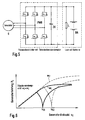
Die prinzipielle Anordnung des Gesamtsystems ist in
Die gewünschte Soll-Leistung des Generators Psoll wird durch einen Spannungsregler, beispielsweise einen PI-Regler, mit Hilfe der Regelabweichung zwischen Sollwert und Istwert der Batteriespannung UBsoll-UBist ermittelt.
Eine Vorrichtung zur Lage- und Drehzahlerkennung ermittelt die Rotorlage und die Generatordrehzahl. Die Verfahren zur Lage- und Drehzahlerkennung können beispielsweise auf optischen, magnetischen oder mechanischen Prinzipien beruhen. Desweiteren existieren auch sensorlose Verfahren die aus den Klemmenwerten der Maschine die Lage des Läufers und dessen Drehzahl ermitteln. Diese Verfahren sind bekannt und sollen deshalb hier nicht weiter beschrieben werden.The desired nominal power of the generator P soll is determined by a voltage regulator, for example a PI controller, with the aid of the control deviation between the setpoint and the actual value of the battery voltage U Bset -U Bist .
A device for position and speed detection determines the rotor position and the generator speed. The method for position and speed detection can be based for example on optical, magnetic or mechanical principles. Furthermore, there are also sensorless methods which determine the position of the rotor and its speed from the terminal values of the machine. These methods are known and will therefore not be described further here.
Eingangsgrößen für den übergeordneten Regler sind die gewünschte Generatorleistung PSoll, die Drehzahl nG und die Zwischenkreisspannung UBist . Durch den übergeordneten Regler wird wahlweise einer von vier Regelbereichen ausgewählt. Ausgegebene Sollwerte des übergeordneten Reglers sind, wie in Bild 2 definiert, der Betrag IsSoll und die Phasenlage ΨSoll des Strangstroms bzw. die Längs- und Querkomponenten des Strangstroms IdSoll, IqSoll, sowie der Sollwert des Erregerstroms IESoll. Dadurch kann für jeden Drehzahlpunkt und jede, von dem Spannungsregler angeforderte Generatorleistung, der jeweils günstigste Betriebspunkt frei ausgewählt werden.Input variables for the higher-level controller are the desired generator power P setpoint , the speed n G and the intermediate circuit voltage U Bist . The higher-level controller optionally selects one of four control ranges. The setpoint values of the higher-level controller are, as defined in Fig. 2, the amount Is set and the phase position Ψ setpoint of the phase current or the longitudinal and transverse components of the phase current I dsoll , I qsoll , as well as the setpoint value of the excitation current I ESoll . As a result, the most favorable operating point can be freely selected for each speed point and each generator power requested by the voltage regulator.
Eingangsgrößen des Ständerstromreglers sind die Rotorlage und die Generatordrehzahl nG, die Sollwerte der Strangströme und die gemessenen Leiterströme IList1 und IList2. Aus den gemessenen zwei Leiterströmen können die Strangsströme des Generators durch Rechnung ermittelt werden. Alternativ können auch alle drei Leiterströme oder zwei bzw. drei Strangströme direkt gemessen werden.Input variables of the stator current regulator are the rotor position and the generator speed n G , the setpoint values of the phase currents and the measured phase currents I List1 and I List2 . From the measured two phase currents, the phase currents of the generator can be determined by calculation. Alternatively, all three phase currents or two or three phase currents can be measured directly.
Der Ständerstromregler steuert die 6 Schalter des Pulswechselrichters (
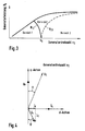
Der prinzipielle Verlauf der Regelbereiche 1- 3 ist in
Beim Betrieb mit Drehzahlen, die links der Drehzahllinie N23 sind, kann beim Betrieb mit passiver B6- Brücke keine Leistung entnommen werden, da die Ausgangsspannung des Generators in diesem Fall kleiner als die Bordnetzspannung UB ist. Die Drehzahllinie N23 entspricht dem Vollastbetrieb des Generators mit einer passiven B6- Brücke. Mit Hilfe der Regelbereiche 1 und 2 kann der Generator auch in sehr niedrigen Drehzahlbereichen Leistung erzeugen. Die bei der passiven Gleichrichtung wichtige Angehdrehzahl n0 ist damit mit Hilfe des erfindungsgemäßen Verfahrens nicht mehr von Bedeutung.When operating at speeds that are to the left of the speed line N 23 , no power can be taken out when operating with a passive B6 bridge because the output voltage of the Generator is smaller than the vehicle electrical system voltage U B in this case. The speed line N 23 corresponds to the full load operation of the generator with a passive B6 bridge. With the help of the control ranges 1 and 2, the generator can generate power even in very low speed ranges. The important in the passive rectification Angehdrehzahl n 0 is thus no longer of importance with the aid of the method according to the invention.
In
Die Regelbereiche 1-3 repräsentieren auch Bereiche mit unterschiedlichem Wirkungsgrad. Durch Veränderung der Ständerwicklungszahl kann daher sowohl das Leistungs- als auch das Wirkungsgradverhalten der Lastkennlinie anpaßt werden. Beispielsweise kann auf diese Weise erreicht werden, daß die Leerlaufdrehzahl des Kfz durch den wirkungsgradoptimalen Regelbereich 1 abgedeckt wird.The control ranges 1-3 also represent areas with different efficiency. By changing the stator winding number, therefore, both the power and the efficiency behavior of the load characteristic can be adjusted. For example, can be achieved in this way that the idle speed of the vehicle is covered by the efficiency-
Durch den Regelbereich 1 wird der untere Drehzahlbereich des Generators abgedeckt. In diesem Regelbereich wird der Erregerstrom IE auf seinen maximal möglichen Wert gesetzt, d.h. IE = IEmax Dadurch wird im unteren Drehzahlbereich die Polradspannung maximiert. Auf Grund der geringen Drehzahl ist die Strangspannung US im Vergleich zur Bordnetzspannung UB stets so klein, daß der Spannungsstellbereich des Pulswechselrichters Umax im Regelbereich 1 nicht überschritten wird. Die Strangsspannung US ist daher stets kleiner, als der durch den Pulswechselrichter einstellbare Maximalwert Umax. Die Phasenlage und der Betrag der Strangströme kann daher ohne Einschränkung auf maximale Ausgangsleistung der Maschine eingestellt werden. Der maximal mögliche Strangstrom wird nur durch die Erwärmung der Maschine beschränkt. Bei konstantem Strangsstrom IS nimmt im Regelbereich 1 die maximale Ausgangsleistung der Maschine proportional mit der Drehzahl zu.The
Mit dem in Bild 4 definiertem Winkel ψ ergibt sich mit den Längs- und Querströmen Id und Iq ![]()
für die Ausgangsleistung einer Synchronschenkelpolmaschine: 
- ω: elektrische Kreisfrequenz der Ständerströme
- Mde : Koppelinduktivität zwischen Rotor und Stator
for the output power of a synchronous shank pole machine:
- ω: electrical angular frequency of the stator currents
- M de : Coupling inductance between rotor and stator
Aus der obigen Gleichung IS=IS(PGEN, ψ) kann für eine gewünschte Solleistung des Generators PGEN ein optimaler Winkel ψopt ermittelt werden, bei dem der Strangstrom ein Minimum annimmt.From the above equation I S = I S (P GEN , ψ), for a desired nominal power of the generator P GEN, an optimum angle ψ opt at which the phase current assumes a minimum can be determined.
Mit 
wird näherungsweise 

becomes approximate
Die Minimierung des Strangstroms durch die Einstellung eines optimalen Winkels ψopt für eine gewünschte Solleistung PGEN führt bei maximal möglichem Erregerstrom IE=IEmax damit zu minimierten ohmschen Strangverlusten. Da die elektrischen ohmschen Verluste in den Strangwicklungen, abgesehen von sehr kleinen Leistungen, stets wesentlich größer als die elektrischen Verluste im Erregerkreis sind, arbeitet die Maschine im Regelbereich 1 mit maximalem Wirkungsgrad.The minimization of the phase current through the setting of an optimum angle ψ opt for a desired nominal power P GEN thus leads to minimized ohmic phase losses at the maximum possible excitation current I E = I Emax . Since the electrical resistive losses in the strand windings, apart from very small powers, are always substantially greater than the electrical losses in the exciter circuit, the machine operates in the
Ab einer bestimmten, leistungsabhängigen Drehzahl, in
Im Regelbereich 2 wird weiterhin IE =IEmax gesetzt. Nun wird jedoch die Phasenlage des Strangstroms so gewählt, daß die Strangspannung den maximalen, vom Pulswechselrichter einstellbaren Wert US=Umax einnimmt. Die Phasenlage des Strangstroms wird so gewählt, daß durch eine Schwächung des Luftspaltfeldes der Spannungsstellbereich Umax des Pulswechselrichters nicht überschritten wird.In
Mit dem Polradwinkel δ und konstanter Strangspannung US=Umax ergibt sich die Ausgangsleistung des Generators zu: 
Bei gegebener maximaler, konstanter Strangspannung Umax kann über Variation des Polradwinkels δ die gewünschte Generatorleistung eingestellt werden. Zu jeder gewünschten Solleistung kann, im Rahmen der Leistungsfähigkeit des Generators, ein bestimmter Polradwinkel δ = δ(Psoll) eingestellt werden.For a given maximum, constant phase voltage U max , the desired generator power can be set by varying the rotor angle δ. For each desired target power, a specific rotor angle δ = δ (P soll ) can be set, within the framework of the generator's capacity.
Wird der Polradwinkel δ = δ(Psoll) in der Maschine eingestellt, so wird der Stellbereich des Pulswechselrichters nicht überschritten und die Bedingung US = Umax eingehalten.If the rotor angle δ = δ (P soll ) is set in the machine, then the control range of the pulse-controlled inverter is not exceeded and the condition U S = U max is maintained.
Der einzustellende Längs- und Querstrom ergibt sich zu 

Mit IE, Id und Iq ist der Maschinenzustand in Abhängigkeit von der gewünschten Solleistung PGEN eindeutig definiert. Im Bereich 2 nimmt die Maschine Blindleistung PB auf. Mit abnehmender Ausgangsleistung (Teillastbetrieb) wird schließlich cosϕ=1 erreicht, das heißt Strangstrom und Strangsspannung sind in Phase. Die Drehzahllinie N23 beschreibt diese Grenze. Bei noch kleineren Leistungen ist es dann jedoch sinnvoll, die Maschine mit cosϕ=1 weiter zu betreiben, um den Wirkungsgrad zu maximieren. Dies wird durch Regelbereiche 3 realisiert.With I E , I d and Iq the machine state is clearly defined depending on the desired target power P GEN . In
Der Regelbereich 3 ist gekennzeichnet durch den Betrieb des Generators mit Leistungsfaktor cosϕ =1, d.h. Strangstrom und Strangspannung sind in Phase. Der Regelbereich 3 entspricht dem Betrieb des Generators mit passiver Diodengleichrichtung. Dieser Regelbereich wird bei Teillastbetrieb ab dem mittleren Drehzahlbereich eingestellt. Für den hier vorliegenden Fall einer konstanten Strangsspannung US=Umax ergibt sich ein maximaler Wirkungsgrad des Generators. Um diesen Zustand einzustellen, wird der Erregerstrom so geregelt, daß sich ϕ=0 ergibt, das heißt die Blindleistung PB=0 wird. Leistungen, die oberhalb der Grenzlinie N23 liegen, können durch den Regelbereich 3 nicht erzeugt werden, da für diesen Fall ein Erregerstrom IE>IEmax notwendig wird.The
Der Betrag des Strangstroms ergibt für den Regelbereich 3 zu 
Der gesuchte Polradwinkel δ, die Längs- und Querströme Id, Iq und der Erregerstrom IE berechnen sich aus den Maschinengleichungen der Schenkelpolsynchronmaschine zu 

Damit ist die Maschinenführung für den Regelbereich 3 vollständig definiert.The desired pole wheel angle δ, the longitudinal and transverse currents I d , I q and the excitation current I E are calculated from the machine equations of the salient pole synchronous machine
Thus, the machine guide for the
Mit den im Regelbereich 1- 3 beschriebenen Regelstrukturen werden alle normalen Betriebszustände der Maschine abgedeckt.The control structures described in the control area 1-3 cover all normal operating conditions of the machine.
Der im folgenden beschriebene Regelbereich 4 dient zum einen dazu, bei extremen Lastabwürfen eine hohe Regeldynamik sicherzustellen. Zum anderen stellt diese Regelfunktion eine zusätzliche Sicherheitsfunktion gegen Überspannungen dar.The control range 4 described below serves on the one hand to ensure a high control dynamics under extreme load drops. On the other hand, this control function provides an additional safety function against overvoltages.
Überschreitet UBist eine einstellbare Überspannungsschwelle, so wird der normale Pulswechselrichterbetrieb verlassen und mit Hilfe der Schalter des Pulswechselrichters die 3-phasigen Ausgänge des Generators kurzgeschlossen. Dadurch sinkt die Überspannung sehr schnell ab. Gleichzeitig wird der Erregerstrom der Maschine, beispielsweise durch eine Schnellentregung, reduziert. Erreicht die Ausgangsspannung eine einstellbare Unterspannungsschwelle, die unterhalb dem Sollwert der Ausgangsspannung UBsoll liegt, so wird die Maschine wieder entsprechend Regelbereich 1- 3 geführt.If U Bist exceeds an adjustable overvoltage threshold, normal PWM inverter operation is exited and the 3-phase outputs of the generator are short-circuited with the aid of the switches of the pulse-controlled inverter. This reduces the overvoltage very quickly. At the same time, the exciter current of the machine is reduced, for example by rapid de-excitation. If the output voltage reaches an adjustable undervoltage threshold below the Setpoint of the output voltage U Bsetpoint , the machine is again guided according to control range 1-3.
Prinzipiell ist es möglich, die Grenzen zwischen den einzelnen Regelbereichen durch numerische Berechnung zu ermitteln und mit Hilfe der dargestellten Gleichungen den Erregerstrom sowie die Längs- und Querströme zu ermitteln. Dies führt jedoch zu einem sehr hohen numerischen Aufwand. Soll das Gesamtsystem jedoch im Kraftfahrzeug realisiert werden, so steht nur die begrenzte Rechenleistung der im Kfz aus Kostengründen einsetzbaren Controllern zur Verfügung.In principle, it is possible to determine the boundaries between the individual control ranges by numerical calculation and to determine the excitation current and the longitudinal and transverse currents with the aid of the equations shown. However, this leads to a very high numerical effort. However, if the overall system is to be implemented in the motor vehicle, then only the limited computing power of the controllers which can be used in the motor vehicle for cost reasons is available.
Eine Möglichkeit diese Schwierigkeit zu umgehen, besteht beispielsweise in einem tabellenorientierten Verfahren. Der übergeordnete Regler besitzt die Eingänge Psoll. nG, Ub und die Ausgänge IE , Id und Iq , bzw. Is und ψ. Diese Abhängigkeit kann mit Hilfe einer mehrdimensionalen Tabelle abgebildet werden. Diese Tabelle enthält die off-line berechneten Gleichungen des übergeordneten Reglers.(Regelbereich 1- 4)One way around this difficulty is, for example, in a table-oriented method. The higher-level controller has inputs P soll. n G , U b and the outputs I E , Id and Iq, or I s and ψ. This dependency can be mapped using a multi-dimensional table. This table contains the off-line calculated equations of the higher order controller (control range 1- 4)
Claims (6)
- Method for controlling a generator, which has a field winding, so as to optimize power and efficiency, having an associated converter bridge, in which method the field current (IE) flowing through the field winding is controlled such that an output voltage which is delivered by the generator reaches a predefinable level, and that, in addition, the phase currents of the generator are controlled, with at least three control ranges being formed, in which the field current and the phase currents of the generator are controlled in accordance with different criteria, characterized in that, in a first control range, the field current is set to its maximum possible value, with the phase voltage being lower than the maximum value that can be set by the pulse-controlled inverter, in that, in a second control range, the field current is likewise set to its maximum value but the phase angle of the phase current is selected such that the phase voltage assumes the maximum possible value, and in that, in a third control range, the generator is operated such that the phase current and phase voltage are in phase and therefore the power factor becomes cos ϕ=1 and the field current is controlled such that an angle of ϕ=0 is produced.
- Method according to Claim 1, characterized in that the generator is a synchronous machine.
- Method according to Claim 1, characterized in that the three control ranges are formed as a function of the output power (PGen) of the generator and/or the rotation speed of the generator (nG).
- Method according to Claim 1 or 2, characterized in that control is performed such that the field current and the magnitude and phase of the phase current or phase currents can be freely selected for each rotation speed of the generator and each desired generator power.
- Method according to one of the preceding claims, characterized in that, in a fourth control range, the generator windings are shorted by corresponding actuation of the converter elements, and the field current is reduced, after a predefinable voltage threshold is exceeded.
- Method according to one of the preceding claims, characterized in that the variables which are required for control, that is setpoint value of the field current IEset and of the in-phase and quadrature components of the phase current Idset and Iqset, are determined with the aid of multidimensional tables.
Applications Claiming Priority (3)
| Application Number | Priority Date | Filing Date | Title |
|---|---|---|---|
| DE19849889 | 1998-10-29 | ||
| DE19849889A DE19849889A1 (en) | 1998-10-29 | 1998-10-29 | Process for the performance and efficiency-optimized control of synchronous machines |
| PCT/DE1999/003416 WO2000027023A1 (en) | 1998-10-29 | 1999-10-27 | Method for the optimized control in terms of output and efficiency of synchronous machines |
Publications (2)
| Publication Number | Publication Date |
|---|---|
| EP1051800A1 EP1051800A1 (en) | 2000-11-15 |
| EP1051800B1 true EP1051800B1 (en) | 2012-09-05 |
Family
ID=7886057
Family Applications (1)
| Application Number | Title | Priority Date | Filing Date |
|---|---|---|---|
| EP99960816A Expired - Lifetime EP1051800B1 (en) | 1998-10-29 | 1999-10-27 | Method for the optimized control in terms of output and efficiency of synchronous machines |
Country Status (11)
| Country | Link |
|---|---|
| US (1) | US6359421B1 (en) |
| EP (1) | EP1051800B1 (en) |
| JP (1) | JP2002530040A (en) |
| KR (1) | KR100766283B1 (en) |
| CN (1) | CN1200507C (en) |
| BR (1) | BR9907074A (en) |
| DE (1) | DE19849889A1 (en) |
| HU (1) | HU223993B1 (en) |
| PL (1) | PL198697B1 (en) |
| RU (1) | RU2235412C2 (en) |
| WO (1) | WO2000027023A1 (en) |
Families Citing this family (42)
| Publication number | Priority date | Publication date | Assignee | Title |
|---|---|---|---|---|
| DE10036099A1 (en) * | 2000-07-25 | 2002-02-14 | Bosch Gmbh Robert | Method for controlling an electrical machine with a pulse inverter |
| DE10036869A1 (en) * | 2000-07-28 | 2002-02-21 | Bosch Gmbh Robert | Method for estimating the pole wheel position on a claw pole machine |
| DE10044181A1 (en) * | 2000-09-07 | 2002-04-04 | Bosch Gmbh Robert | Controller structure for electrical machines |
| JP3545693B2 (en) * | 2000-11-01 | 2004-07-21 | 三菱電機株式会社 | Control method of claw pole synchronous machine |
| DE10106944B4 (en) * | 2001-02-15 | 2010-08-05 | Robert Bosch Gmbh | Method for controlling the temperature of an electrical machine |
| DE10110939B4 (en) * | 2001-03-07 | 2004-07-08 | Mühlbauer Ag | Method and device for hot press connecting a chip module to a carrier substrate |
| DE10130339A1 (en) * | 2001-06-26 | 2003-01-02 | Abb Research Ltd | Improving usefulness and reliability of power plant e.g. wind power plant, involves using diode rectifier(s) or controlled rectifier(s) in fundamental frequency clocking mode to convert effective electrical power |
| US6703718B2 (en) * | 2001-10-12 | 2004-03-09 | David Gregory Calley | Wind turbine controller |
| JP4236870B2 (en) * | 2002-06-03 | 2009-03-11 | 三菱電機株式会社 | Control device and control method for rotating electrical machine for vehicle |
| WO2004034562A1 (en) | 2002-10-11 | 2004-04-22 | Mitsuba Corporation | Control method of generator |
| US6803748B2 (en) * | 2003-02-03 | 2004-10-12 | Delphi Technologies, Inc. | System and method for controlling load dump voltage of a synchronous machine |
| JP4113848B2 (en) | 2004-02-18 | 2008-07-09 | 三菱電機株式会社 | Motor generator control device |
| CN101263650A (en) * | 2005-07-15 | 2008-09-10 | 西南风力公司 | Wind turbine and method of manufacture |
| FR2892077B1 (en) * | 2005-10-17 | 2009-05-15 | Peugeot Citroen Automobiles Sa | POWER SUPPLY CIRCUIT FOR ELECTRICAL POWER OF A MOTOR VEHICLE |
| FR2897656B1 (en) * | 2006-02-23 | 2011-05-20 | Renault Sas | METHOD AND SYSTEM FOR CONTROLLING A LOW-VOLTAGE POWER-UP PREHEATING CANDLE, A DIESEL ENGINE AIR / FUEL MIXTURE |
| US7623331B2 (en) * | 2006-10-06 | 2009-11-24 | Remy International, Inc. | Method and system for improving voltage regulator accuracy in vehicle alternators |
| FI119898B (en) * | 2007-02-14 | 2009-04-30 | Konecranes Oyj | The generator assembly |
| CN201811997U (en) * | 2007-11-13 | 2011-04-27 | 艾默生环境优化技术有限公司 | Three-phase detection equipment |
| DE102008042352A1 (en) * | 2008-09-25 | 2010-04-08 | Robert Bosch Gmbh | Control of a synchronous rectifier |
| DE102008042931A1 (en) | 2008-10-17 | 2010-04-22 | Robert Bosch Gmbh | Method and device for field-oriented control of a synchronous machine |
| FR2948512A1 (en) * | 2009-07-24 | 2011-01-28 | Peugeot Citroen Automobiles Sa | Power supply device controlling method for e.g. motor vehicle, involves determining set point value of alternator excitation command according to rotation speed of rotor of alternator and electric power consumed by load |
| DE102009045351A1 (en) | 2009-10-06 | 2011-04-14 | Robert Bosch Gmbh | Method for operating a drive unit and drive unit |
| TWI398742B (en) * | 2009-12-02 | 2013-06-11 | Univ Nat Cheng Kung | Method for optimizing generator parameters by taguchi method and fuzzy inference |
| DE102010043095A1 (en) * | 2010-10-29 | 2012-05-03 | Robert Bosch Gmbh | A method of reducing a voltage ripple due to rotational nonuniformity of an internal combustion engine driven generator |
| US20120126758A1 (en) * | 2010-11-19 | 2012-05-24 | Hamilton Sundstrand Corporation | High voltage dc power generation |
| DE102010062338A1 (en) | 2010-12-02 | 2012-06-06 | Robert Bosch Gmbh | Method and device for operating a separately excited electrical machine |
| FR2971648B1 (en) * | 2011-02-16 | 2016-10-14 | Moteurs Leroy-Somer | VARIABLE-RATE OPERATING ASSEMBLY HAVING SYNCHRONOUS ROTOR-ROLLER ALTERNATOR AND CONVERTER |
| DE102011076999A1 (en) | 2011-05-26 | 2012-11-29 | Robert Bosch Gmbh | Method for operating an electrical machine in a motor vehicle |
| FR2979765B1 (en) * | 2011-09-01 | 2015-06-26 | Leroy Somer Moteurs | METHOD FOR REGULATING AN ELECTROGEN GROUP |
| DE102012204751B4 (en) * | 2012-03-26 | 2018-12-20 | Robert Bosch Gmbh | Method for checking a field current measurement of a synchronous machine in generator mode |
| FR3004603B1 (en) * | 2013-04-10 | 2015-07-03 | Valeo Systemes De Controle Moteur | ROTARY DRIVE SYSTEM, INVERTER CONTROL METHOD, AND COMPUTER PROGRAM |
| US20150249417A1 (en) * | 2013-12-30 | 2015-09-03 | Rolls-Royce Corporation | Synchronous generator controller based on flux optimizer |
| DE102014102352A1 (en) * | 2014-02-24 | 2015-08-27 | Ge Energy Power Conversion Technology Limited | Battery storage system with arc fault protection, energy conversion system and protection method |
| DE102015009490B4 (en) * | 2015-07-22 | 2020-04-02 | Audi Ag | Voltage stabilization of a motor vehicle generator |
| EP3264587B1 (en) | 2016-06-28 | 2021-02-17 | MARTIN Special Technics GmbH | Energy generation system comprising a generator and method for operating such an energy generation system |
| CN107154762B (en) * | 2017-05-17 | 2019-04-23 | 苏州半唐电子有限公司 | A kind of control method without sensing permanent magnet synchronous motor optimum efficiency tracking |
| RU2645387C1 (en) * | 2017-05-30 | 2018-02-21 | Федеральное государственное бюджетное образовательное учреждение высшего образования "Государственный университет морского и речного флота имени адмирала С.О. Макарова" | Method of distributing the load between parallel operating ship diesel driven generators |
| FR3083025B1 (en) * | 2018-06-20 | 2020-07-10 | Valeo Equipements Electriques Moteur | IMPROVED REGULATION SYSTEM FOR A ROTATING ELECTRIC MACHINE |
| CA3119273A1 (en) | 2018-11-09 | 2020-05-14 | Iocurrents, Inc. | Machine learning-based prediction, planning, and optimization of trip time, trip cost, and/or pollutant emission during navigation |
| RU2704313C1 (en) * | 2018-11-26 | 2019-10-28 | Федеральное государственное бюджетное образовательное учреждение высшего образования "Казанский государственный энергетический университет" (ФГБОУ ВО "КГЭУ") | System for boosting excitation of self-contained synchronous generator included in electrical system, using energy accumulators based on storage batteries and high-power supercapacitors |
| FR3092209A1 (en) * | 2019-01-29 | 2020-07-31 | Psa Automobiles Sa | PROCESS AND SYSTEM FOR MANAGING THE POWER SUPPLY OF AN ON-BOARD NETWORK OF A MOTOR VEHICLE |
| RU2721477C1 (en) * | 2019-12-03 | 2020-05-19 | федеральное государственное бюджетное образовательное учреждение высшего образования "Нижегородский государственный технический университет им. Р.Е. Алексеева" (НГТУ) | Control system of electric energy storages for expansion of range of permissible modes of generating installations of sources of distributed generation at voltage failures |
Family Cites Families (10)
| Publication number | Priority date | Publication date | Assignee | Title |
|---|---|---|---|---|
| US3908130A (en) * | 1974-08-30 | 1975-09-23 | Gen Electric | Starter-generator utilizing phase controlled rectifiers to drive a dynamoelectric machine as a brushless motor in the starting mode to increase the torque output of the machine through phase angle control by reducing the machine counter EMF |
| DE3013473A1 (en) * | 1980-04-08 | 1981-10-15 | Braun Ag, 6000 Frankfurt | METHOD AND ARRANGEMENT FOR CONTROLLING AND CONTROLLING A MOTOR WITH PERMANENT MAGNETIC RUNNER |
| US4816736A (en) * | 1987-03-12 | 1989-03-28 | Globe-Union Inc. | Polyphase alternator and dual voltage battery charging system for multiple voltage loads |
| JP2569360B2 (en) * | 1988-11-25 | 1997-01-08 | 多摩川精機株式会社 | Generator |
| US5663631A (en) | 1994-07-19 | 1997-09-02 | Nippondenso Co., Ltd. | Generator with circuitry for controlling power generation based on rotational speed |
| DE69530828T2 (en) | 1994-12-16 | 2004-01-22 | Delphi Technologies, Inc., Troy | Torque and output control of an internal combustion engine |
| US5648705A (en) | 1995-09-05 | 1997-07-15 | Ford Motor Company | Motor vehicle alternator and methods of operation |
| DE19733212A1 (en) | 1997-08-01 | 1999-02-04 | Bosch Gmbh Robert | Method for controlling a generator that can be driven by an internal combustion engine |
| DE19733221A1 (en) * | 1997-08-01 | 1999-02-04 | Bosch Gmbh Robert | Process for regulating a generator |
| US6181112B1 (en) * | 1998-12-10 | 2001-01-30 | Hamilton Sundstrand Corporation | Apparatus and method for limiting generator peak voltage |
-
1998
- 1998-10-29 DE DE19849889A patent/DE19849889A1/en not_active Ceased
-
1999
- 1999-10-27 EP EP99960816A patent/EP1051800B1/en not_active Expired - Lifetime
- 1999-10-27 KR KR1020007007223A patent/KR100766283B1/en not_active IP Right Cessation
- 1999-10-27 US US09/582,593 patent/US6359421B1/en not_active Expired - Fee Related
- 1999-10-27 PL PL341570A patent/PL198697B1/en unknown
- 1999-10-27 JP JP2000580294A patent/JP2002530040A/en active Pending
- 1999-10-27 HU HU0101221A patent/HU223993B1/en not_active IP Right Cessation
- 1999-10-27 RU RU2000120181/09A patent/RU2235412C2/en not_active IP Right Cessation
- 1999-10-27 CN CNB998019615A patent/CN1200507C/en not_active Expired - Fee Related
- 1999-10-27 WO PCT/DE1999/003416 patent/WO2000027023A1/en active Application Filing
- 1999-10-27 BR BR9907074-0A patent/BR9907074A/en not_active IP Right Cessation
Also Published As
| Publication number | Publication date |
|---|---|
| PL341570A1 (en) | 2001-04-23 |
| EP1051800A1 (en) | 2000-11-15 |
| HUP0101221A3 (en) | 2002-10-28 |
| CN1287710A (en) | 2001-03-14 |
| HU223993B1 (en) | 2005-04-28 |
| HUP0101221A2 (en) | 2001-08-28 |
| WO2000027023A1 (en) | 2000-05-11 |
| KR20010033700A (en) | 2001-04-25 |
| KR100766283B1 (en) | 2007-10-11 |
| JP2002530040A (en) | 2002-09-10 |
| PL198697B1 (en) | 2008-07-31 |
| CN1200507C (en) | 2005-05-04 |
| RU2235412C2 (en) | 2004-08-27 |
| BR9907074A (en) | 2000-10-17 |
| DE19849889A1 (en) | 2000-05-04 |
| US6359421B1 (en) | 2002-03-19 |
Similar Documents
| Publication | Publication Date | Title |
|---|---|---|
| EP1051800B1 (en) | Method for the optimized control in terms of output and efficiency of synchronous machines | |
| EP0875089B1 (en) | Power supply system | |
| DE10206955B4 (en) | Steering control unit | |
| EP0999953B1 (en) | Method and device for regulating a generator capable of being driven by an internal combustion engine | |
| EP1305876B1 (en) | Method for controlling an electrical machine by means of a pulse-width modulation inverter | |
| EP0929927B1 (en) | Method for regulating a generator | |
| WO2019042919A1 (en) | Method for controlling a multiphase separately excited synchronous generator in a wind turbine | |
| DE112016000455T5 (en) | Control device for a rotating electrical machine | |
| EP0772904B1 (en) | Power supply device with two output voltages | |
| WO2003094338A1 (en) | Method and device for the sensor reduced regulation of a permanent magnet excited synchronous machine | |
| EP3264587B1 (en) | Energy generation system comprising a generator and method for operating such an energy generation system | |
| WO2012107330A2 (en) | Method for adjusting an actual torque delivered by an electric motor in a motor vehicle to a target torque | |
| DE102010019151B4 (en) | Method and device for energy transmission in a motor vehicle | |
| EP3695508B1 (en) | Method for operating an electric machine | |
| EP3172831A1 (en) | Method for operating an at least generator-operable electric machine and means for the implementation thereof | |
| EP3695509B1 (en) | Method for changing between block control and pwm control of an electric machine | |
| WO2018029309A1 (en) | Method for operating a current converter and a current converter operating according to said method | |
| EP3685504B1 (en) | Method for operating a separately excited electric machine | |
| EP3476038A1 (en) | Method for controlling a synchronous machine and control device for a synchronous machine | |
| EP3685503B1 (en) | Method for determining a maximally adjustable torque of an electric machine | |
| DE102017212778A1 (en) | Control of a 6-phase permanently excited synchronous machine in the event of a fault in a circuit breaker short-circuit | |
| DE102004059609A1 (en) | Controller for rotating electric machine for vehicle, has magnetic field electric current command restraining unit that limits each phase of line electric current when rotating electric machine functions as electric generator | |
| DE102013226210A1 (en) | A power supply device and method for controlling the power supply device | |
| DE102007006154A1 (en) | Motor control device for controlling motor by alternating current-cycloconverter, has current measuring device for measuring motor currents |
Legal Events
| Date | Code | Title | Description |
|---|---|---|---|
| PUAI | Public reference made under article 153(3) epc to a published international application that has entered the european phase |
Free format text: ORIGINAL CODE: 0009012 |
|
| AK | Designated contracting states |
Kind code of ref document: A1 Designated state(s): AT BE CH CY DE DK ES FI FR GB GR IE IT LI LU MC NL PT SE |
|
| 17P | Request for examination filed |
Effective date: 20001113 |
|
| RBV | Designated contracting states (corrected) |
Designated state(s): DE ES FR GB IT SE |
|
| 17Q | First examination report despatched |
Effective date: 20100128 |
|
| GRAP | Despatch of communication of intention to grant a patent |
Free format text: ORIGINAL CODE: EPIDOSNIGR1 |
|
| GRAS | Grant fee paid |
Free format text: ORIGINAL CODE: EPIDOSNIGR3 |
|
| GRAA | (expected) grant |
Free format text: ORIGINAL CODE: 0009210 |
|
| AK | Designated contracting states |
Kind code of ref document: B1 Designated state(s): DE ES FR GB IT SE |
|
| REG | Reference to a national code |
Ref country code: GB Ref legal event code: FG4D Free format text: NOT ENGLISH |
|
| REG | Reference to a national code |
Ref country code: DE Ref legal event code: R096 Ref document number: 59915351 Country of ref document: DE Effective date: 20121031 |
|
| PG25 | Lapsed in a contracting state [announced via postgrant information from national office to epo] |
Ref country code: SE Free format text: LAPSE BECAUSE OF FAILURE TO SUBMIT A TRANSLATION OF THE DESCRIPTION OR TO PAY THE FEE WITHIN THE PRESCRIBED TIME-LIMIT Effective date: 20120905 |
|
| PG25 | Lapsed in a contracting state [announced via postgrant information from national office to epo] |
Ref country code: ES Free format text: LAPSE BECAUSE OF FAILURE TO SUBMIT A TRANSLATION OF THE DESCRIPTION OR TO PAY THE FEE WITHIN THE PRESCRIBED TIME-LIMIT Effective date: 20121216 |
|
| PGFP | Annual fee paid to national office [announced via postgrant information from national office to epo] |
Ref country code: DE Payment date: 20121217 Year of fee payment: 14 Ref country code: FR Payment date: 20130123 Year of fee payment: 14 |
|
| PLBE | No opposition filed within time limit |
Free format text: ORIGINAL CODE: 0009261 |
|
| STAA | Information on the status of an ep patent application or granted ep patent |
Free format text: STATUS: NO OPPOSITION FILED WITHIN TIME LIMIT |
|
| 26N | No opposition filed |
Effective date: 20130606 |
|
| GBPC | Gb: european patent ceased through non-payment of renewal fee |
Effective date: 20121205 |
|
| PG25 | Lapsed in a contracting state [announced via postgrant information from national office to epo] |
Ref country code: IT Free format text: LAPSE BECAUSE OF FAILURE TO SUBMIT A TRANSLATION OF THE DESCRIPTION OR TO PAY THE FEE WITHIN THE PRESCRIBED TIME-LIMIT Effective date: 20120905 |
|
| REG | Reference to a national code |
Ref country code: DE Ref legal event code: R097 Ref document number: 59915351 Country of ref document: DE Effective date: 20130606 |
|
| PG25 | Lapsed in a contracting state [announced via postgrant information from national office to epo] |
Ref country code: GB Free format text: LAPSE BECAUSE OF NON-PAYMENT OF DUE FEES Effective date: 20121205 |
|
| REG | Reference to a national code |
Ref country code: DE Ref legal event code: R119 Ref document number: 59915351 Country of ref document: DE Effective date: 20140501 |
|
| REG | Reference to a national code |
Ref country code: FR Ref legal event code: ST Effective date: 20140630 |
|
| PG25 | Lapsed in a contracting state [announced via postgrant information from national office to epo] |
Ref country code: FR Free format text: LAPSE BECAUSE OF NON-PAYMENT OF DUE FEES Effective date: 20131031 Ref country code: DE Free format text: LAPSE BECAUSE OF NON-PAYMENT OF DUE FEES Effective date: 20140501 |