EP1050892A1 - Anordnung zur Strombegrenzung mit einem supraleitenden Transformator - Google Patents
Anordnung zur Strombegrenzung mit einem supraleitenden Transformator Download PDFInfo
- Publication number
- EP1050892A1 EP1050892A1 EP00109310A EP00109310A EP1050892A1 EP 1050892 A1 EP1050892 A1 EP 1050892A1 EP 00109310 A EP00109310 A EP 00109310A EP 00109310 A EP00109310 A EP 00109310A EP 1050892 A1 EP1050892 A1 EP 1050892A1
- Authority
- EP
- European Patent Office
- Prior art keywords
- winding
- superconducting
- primary
- relief
- current
- Prior art date
- Legal status (The legal status is an assumption and is not a legal conclusion. Google has not performed a legal analysis and makes no representation as to the accuracy of the status listed.)
- Granted
Links
Images

Classifications
-
- H—ELECTRICITY
- H02—GENERATION; CONVERSION OR DISTRIBUTION OF ELECTRIC POWER
- H02H—EMERGENCY PROTECTIVE CIRCUIT ARRANGEMENTS
- H02H7/00—Emergency protective circuit arrangements specially adapted for specific types of electric machines or apparatus or for sectionalised protection of cable or line systems, and effecting automatic switching in the event of an undesired change from normal working conditions
- H02H7/001—Emergency protective circuit arrangements specially adapted for specific types of electric machines or apparatus or for sectionalised protection of cable or line systems, and effecting automatic switching in the event of an undesired change from normal working conditions for superconducting apparatus, e.g. coils, lines, machines
-
- H—ELECTRICITY
- H01—ELECTRIC ELEMENTS
- H01F—MAGNETS; INDUCTANCES; TRANSFORMERS; SELECTION OF MATERIALS FOR THEIR MAGNETIC PROPERTIES
- H01F36/00—Transformers with superconductive windings or with windings operating at cryogenic temperature
-
- Y—GENERAL TAGGING OF NEW TECHNOLOGICAL DEVELOPMENTS; GENERAL TAGGING OF CROSS-SECTIONAL TECHNOLOGIES SPANNING OVER SEVERAL SECTIONS OF THE IPC; TECHNICAL SUBJECTS COVERED BY FORMER USPC CROSS-REFERENCE ART COLLECTIONS [XRACs] AND DIGESTS
- Y02—TECHNOLOGIES OR APPLICATIONS FOR MITIGATION OR ADAPTATION AGAINST CLIMATE CHANGE
- Y02E—REDUCTION OF GREENHOUSE GAS [GHG] EMISSIONS, RELATED TO ENERGY GENERATION, TRANSMISSION OR DISTRIBUTION
- Y02E40/00—Technologies for an efficient electrical power generation, transmission or distribution
- Y02E40/60—Superconducting electric elements or equipment; Power systems integrating superconducting elements or equipment
Definitions
- the present invention relates to the field of technical application of superconductors. It concerns an order and a method for limiting current with a superconducting Transformer.
- a superconducting current limiter designed, for example, for an electrical energy distribution network
- This limit value is conventionally referred to as the critical current density j C or, based on a specific conductor cross section, as the critical current I C and is fundamentally dependent on the temperature of the superconductor and the magnetic field penetrating it. If the current in the conductor exceeds the critical value I C in the event of a short circuit, its electrical resistance increases and the short-circuit current is limited. In the case of DE 44 18 050 A1, this takes place via a choke coil, the impedance of which increases suddenly due to its iron core which is no longer shielded.
- a main requirement for current limiters of any kind in electrical power distribution networks is that they are one Limit short-circuit current to a harmless level and after the short circuit has ceased, the nominal current again immediately conduct.
- the circuit should not be interrupted need to be a consumer by the same Current limiter is secured like the short circuit path, not is completely cut off from the energy source.
- a superconductor If a superconductor is subjected to an overcurrent for too long, it heats up to well above the critical temperature T C and may be damaged. A current limiter heated in this way also has considerable resistance if it only has to conduct the rated current after the short circuit has been rectified. The subsequent cooling process to a temperature below the critical temperature T C takes a certain minimum amount of time due to physically predetermined limits with regard to the heat transfer between the superconductor and the cooling medium. This is often longer than the duration of the actual short circuit, so that the power supply to the consumer is interrupted or at least restricted much longer than necessary.
- the invention has for its object a current limiting arrangement based on a superconducting transformer to indicate the most uninterrupted a consumer supplied with energy and with little effort on superconducting material.
- the essence of the invention is in a superconducting transformer one to a first superconducting primary or secondary winding parallel relief path in the form of a second, normal conducting primary or secondary winding to provide.
- first superconducting primary or secondary winding parallel relief path in the form of a second, normal conducting primary or secondary winding to provide.
- second, normal conducting primary or secondary winding In normal operation flows due to the ohmic resistance the normal conductor practically no current through this second or relief winding.
- the critical Value there is also an electrical resistance built up there on and the alternative normal path through the second Winding takes over part of the short-circuit current.
- a first embodiment of the invention is characterized in that the first superconducting winding is dimensioned such that its critical current intensity I C essentially corresponds to the primary or secondary-side nominal current I N to be carried in normal operation.
- the relief winding according to the invention is designed either on the primary or secondary side and only a first superconducting winding is provided on the opposite secondary or primary side.
- the latter is dimensioned so that it remains superconducting even in the event of a short circuit, ie can carry a multiple of its nominal current I N.
- a switch is in Series intended for the first superconducting winding, which is opened shortly after the occurrence of a short circuit and interrupts the current through the superconducting winding. Thereby if the latter is optimally protected, it heats up only slightly and can immediately after the short circuit has ceased be switched back into the circuit.
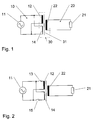
- FIG. 1 shows a circuit which includes a primary circuit 10 with an alternating current source 11, a secondary circuit 20 with a consumer 21 and a transformer 30 with a transformer core 31 arranged between the primary and secondary circuits.
- the source 11 generates a nominal current I N (P) on the primary side, while a nominal current I N (S) on the secondary side flows through the consumer 21.
- the transformer 30 has a first superconducting primary winding 12, which conducts the primary-side nominal current I N (P) without loss.
- Parallel to the first primary winding 12, a second, normally conductive primary winding 14 is provided as a relief winding. Both primary windings 12, 14 interact via the transformer core 31 with a secondary winding 22 of the transformer 30.
- FIG. 2 shows an embodiment variant in which a first switch 13 in series with the first primary winding 12 is provided.
- this switch 13 can the first primary winding 12 is separated from the primary circuit 10 become. Regardless of the existence of the first one can still second switch 15 in series with the second primary winding 14 installed.
- FIG. 3 shows schematically the embodiment variant according to FIG. 2 with a sectional view of the transformer 30.
- All Windings 12, 14, 22 are concentric around a common, with the transformer core 31 identical axis wound.
- the superconducting primary and secondary windings 12, 22 are located in a cryostat 32 filled with a cooling medium 33 and have a radial distance d1.
- the second primary winding 14 is located outside the cryostat 32, as well the two switches 13, 15.
- the radial distance between the second primary winding 14 and the secondary winding 22 designated d2.
- Fig. 4 shows a further embodiment, in which a parallel connection of a damping impedance 16, preferably a resistor, and a third switch 17 in Series to the relief winding 14 is switched.
- the third Switch 17 bridges the impedance in the closed state 16 and can be identical to the above-mentioned second switch 15 his.
- the first superconducting primary winding 12 is connected to the current source 11. If a short circuit now occurs in the secondary circuit 20, the current strength rises sharply on both the primary and secondary side and exceeds the critical current strength I C (P) of the first primary winding 12. A disproportionate voltage drop builds up and the primary winding 12 occurs in the normally conductive Condition about. At the same time, the impedance of the normally conducting second primary winding 14 connected in parallel naturally remains unchanged, so that the short-circuit or overcurrent now commutates from the first into the second primary winding.
- the switch 13 in series with the first primary winding 12 supports them targeted relief still further.
- this is separated from the source 11. This is preferably done in the zero crossing of the flowing through the switch 13 Overcurrent share. So the earliest possible time follows at the latest after half a period, but it is appropriate wait a little longer and the overcurrent through the first primary winding 12, for example after 20-100 ms (at a mains frequency of 50-60 Hz). Until corrected the short circuit, usually after a few 100 ms, there is therefore sufficient time for the first primary winding 12 for re-cooling.
- the second primary winding 14 normally has a large one Ohmic resistance and is, for example, from one Steel wire wrapped. However, it can also be a primary concern copper or very low temperature conductive wire Aluminum can be chosen. In this case, however, in order to In the event of a short circuit, the overcurrent increases too much to prevent by the second primary winding 14, the latter can be provided with an additional leakage impedance.
- Crucial for the interpretation of the the two primary windings 12, 14 is the ratio of the total impedance the second winding 14 to the resistance of the first Winding 12 in the normally conductive state, i.e. after done Limitation of the first overcurrent peak.
- additional damping impedance 16 is for the fast Attenuation of a possibly aperiodic short-circuit current responsible. Accordingly, the impedance 16 after a short time Time, for example within the second AC period (i.e. 20 - 40 ms at 50 Hz mains frequency) after occurrence the short circuit, by closing the third switch 17 be bridged again.
- a wire comes into question which contains a significant proportion of a superconducting phase in a matrix of non-superconducting material which acts as an electrical bypass.
- the critical current strength of this wire is influenced by the wire cross-section or the content of superconductor material. It should be noted that the AC losses are proportional to the volume of the affected superconductor. From this point of view it is also advantageous to dimension the wire so that the nominal current I N corresponds approximately to the critical current I C. This is the case with the primary winding 12 of the transformer 30 shown.
- This wire therefore has a high proportion of superconducting Material on or its matrix is designed to be can temporarily conduct an overcurrent without them itself or the superconducting phase is damaged.
- a matrix made of silver is suitable for this.
- the designation chosen for the primary or secondary circuit 10, 20 is not determined by the source 11 or the consumer 21.
- the person skilled in the art is at liberty to apply the measures characterizing the invention to the secondary side, ie to interchange the designations chosen here from the primary and secondary side.
- the relief winding is advantageously carried out at least on the transformer side with the larger nominal current, which corresponds to the previous statements on the assumption that the transformer steps up the voltage or, in other words, that the primary-side nominal current I N (P) is greater than the secondary-side nominal current I N ( S is.
- the superconducting primary winding 12 is designed for the nominal current I N (P) for the purpose of current limitation and reduction of the alternating current losses and is generously dimensioned for the smaller nominal and short-circuit currents on the secondary side.
- High-temperature superconductor materials which can be cooled to a temperature below their critical temperature T C with liquid nitrogen as cooling medium 33 are particularly suitable.
Landscapes
- Engineering & Computer Science (AREA)
- Power Engineering (AREA)
- Emergency Protection Circuit Devices (AREA)
- Containers, Films, And Cooling For Superconductive Devices (AREA)
Abstract
Description
- 10
- Primärkreis
- 11
- Wechselstromquelle
- 12
- erste, supraleitende Primärwicklung
- 13
- erster Schalter
- 14
- zweite, normalleitende Primärwicklung
- 15
- zweiter Schalter
- 16
- Dämpfungsimpedanz
- 17
- Dritter Schalter
- 20
- Sekundärkreis
- 21
- Verbraucher
- 22
- supraleitende Sekundärwicklung
- 30
- Transformator
- 31
- Transformatorkern
- 32
- Kryostat
- 33
- Kühlmedium
Claims (10)
- Anordnung zur Strombegrenzung, umfassend einen supraleitenden Transformator (30)mit einer supraleitenden Primärwicklung (12), einer supraleitenden Sekundärwicklung (22) und einer zur Primärwicklung (12) oder Sekundärwicklung (22) parallelen Entlastungswicklung (14) , dadurch gekennzeichnet, dass die Entlastungswicklung (14) aus einem normalleitenden Material besteht.
- Anordnung nach Anspruch 1, dadurch gekennzeichnet, dass die Entlastungswicklung (14) parallel zur supraleitenden Primärwicklung (12) geschaltet ist und dass die supraleitende Primärwicklung (12) eine kritische Stromstärke IC(P) aufweist, die im Wesentlichen einem primärseitigen Nennstrom IN(P) des Transformators (30) entspricht.
- Anordnung nach Anspruch 2, dadurch gekennzeichnet, dass die Sekundärwicklung (22) eine kritische Stromstärke IC(S) aufweist, welche grösser ist als ein sekundärseitiger Nennstrom IN(S) des Transformators (30) und dass keine weiteren sekundärseitigen Wicklungen vorgesehen sind.
- Anordnung nach Anspruch 3, dadurch gekennzeichnet, dassa) die Primärwicklung (12) in einem ersten radialen Abstand d1 konzentrisch zur Sekundärwicklung (22) angeordnet ist undb) die Entlastungswicklung (14) in einem zweiten radialen Abstand d2 konzentrisch zur Sekundärwicklung (22) angeordnet ist undc) der zweite radiale Abstand d2 grösser ist als der erste radiale Abstand d1.
- Anordnung nach Anspruch 4, dadurch gekennzeichnet, dass ein Kryostat (32) mit einem Kühlmedium (33) zur Kühlung der Primärwicklung (12) und der Sekundärwicklung (22) vorgesehen ist, und dass die Entlastungswicklung (14) ausserhalb des Kryostaten (32) angeordnet ist.
- Anordnung nach einem der Ansprüche 1 - 5, dadurch gekennzeichnet, dass ein erster Schalter (13) zur Unterbrechung der zur Entlastungswicklung (14) parallelen Primärwicklung (12) beziehungsweise Sekundärwicklung (22) vorgesehen ist.
- Anordnung nach Anspruch 6, dadurch gekennzeichnet, dass ein zweiter Schalter (15) zur Unterbrechung der Entlastungswicklung (14) vorgesehen ist.
- Anordnung nach einem der Ansprüche 1 - 5, dadurch gekennzeichnet, dass eine Parallelschaltung aus einer Dämpfungsimpedanz (16) und einem dritten Schalter (17) in Serie mit der Entlastungswicklung (14) vorgesehen ist.
- Verfahren zur Strombegrenzung mit einer einen supraleitenden Transformator (30) umfassenden Anordnung mit einer zu einem ersten Schalter (13) und einer supraleitenden Primärwicklung (12) oder einer supraleitenden Sekundärwicklung (22) parallelen normalleitenden Entlastungswicklung (14), wobei der erste Schalter (13) nach Auftreten eines Kurzschlusses geöffnet und der ganze primärseitige Strom auf die Entlastungswicklung (14) kommutiert wird, dadurch gekennzeichnet, dass der erste Schalter (13) in einem Nulldurchgang des ihn durchfliessenden Stromes geöffnet wird.
- Verfahren nach Anspruch 8, dadurch gekennzeichnet, dass der erste Schalter (13) innerhalb von 1 bis 5 Wechselstromperioden nach Auftreten des Kurzschlusses geöffnet wird.
Applications Claiming Priority (2)
| Application Number | Priority Date | Filing Date | Title |
|---|---|---|---|
| DE19920443 | 1999-05-04 | ||
| DE19920443A DE19920443A1 (de) | 1999-05-04 | 1999-05-04 | Anordnung zur Strombegrenzung mit einem supraleitenden Transformator |
Publications (2)
| Publication Number | Publication Date |
|---|---|
| EP1050892A1 true EP1050892A1 (de) | 2000-11-08 |
| EP1050892B1 EP1050892B1 (de) | 2008-04-02 |
Family
ID=7906902
Family Applications (1)
| Application Number | Title | Priority Date | Filing Date |
|---|---|---|---|
| EP00109310A Expired - Lifetime EP1050892B1 (de) | 1999-05-04 | 2000-04-29 | Anordnung zur Strombegrenzung mit einem supraleitenden Transformator |
Country Status (6)
| Country | Link |
|---|---|
| US (1) | US6411479B1 (de) |
| EP (1) | EP1050892B1 (de) |
| JP (1) | JP4074046B2 (de) |
| AT (1) | ATE391334T1 (de) |
| DE (2) | DE19920443A1 (de) |
| DK (1) | DK1050892T3 (de) |
Cited By (1)
| Publication number | Priority date | Publication date | Assignee | Title |
|---|---|---|---|---|
| CN117394291A (zh) * | 2023-09-04 | 2024-01-12 | 西南交通大学 | 双面超导薄膜限流组件、混合型超导限流器及限流方法 |
Families Citing this family (7)
| Publication number | Priority date | Publication date | Assignee | Title |
|---|---|---|---|---|
| US7019608B2 (en) * | 2000-03-21 | 2006-03-28 | Metal Manufactures Limited | Superconducting transformer |
| DE10035634A1 (de) * | 2000-07-21 | 2002-02-07 | Siemens Ag | Supraleitungseinrichtung mit induktiver Strombegrenzereinheit unter Verwendung von Hoch-Tc-Supraleitermaterial |
| DE10133531A1 (de) * | 2001-07-11 | 2003-01-30 | Kuesters Eduard Maschf | Langspalt-Walzenpresse zum Entwässern einer Faserstoffbahn |
| US20050197624A1 (en) * | 2004-03-04 | 2005-09-08 | Flowmedica, Inc. | Sheath for use in peripheral interventions |
| DE10358549B4 (de) * | 2003-12-15 | 2005-11-24 | Bruker Biospin Ag | Supraleitendes Magnetsystem mit kontinuierlich arbeitender Flusspumpe und zugehörige Betriebsverfahren |
| KR100763163B1 (ko) * | 2005-12-02 | 2007-10-08 | 엘에스산전 주식회사 | 재폐로 동작이 가능한 초전도 한류 시스템 |
| RU2762827C1 (ru) * | 2021-06-22 | 2021-12-23 | Федеральное государственное бюджетное образовательное учреждение высшего образования «Национальный исследовательский университет «МЭИ» | Ограничитель токов короткого замыкания |
Citations (1)
| Publication number | Priority date | Publication date | Assignee | Title |
|---|---|---|---|---|
| GB1230579A (de) * | 1967-07-24 | 1971-05-05 |
Family Cites Families (4)
| Publication number | Priority date | Publication date | Assignee | Title |
|---|---|---|---|---|
| US4336561A (en) | 1980-01-28 | 1982-06-22 | Westinghouse Electric Corp. | Superconducting transformer |
| US5379020A (en) * | 1993-06-04 | 1995-01-03 | Abb Research Ltd. | High-temperature superconductor and its use |
| DE19524579C2 (de) * | 1995-07-06 | 1997-12-18 | Daimler Benz Ag | Transformator als Strombegrenzer |
| DE19809314A1 (de) * | 1998-03-05 | 1999-09-09 | Abb Research Ltd | Anordnung sowie Verfahren zur Strombegrenzung mit einer supraleitenden Transformatoranordnung in einem elektrischen Schaltkreis |
-
1999
- 1999-05-04 DE DE19920443A patent/DE19920443A1/de not_active Withdrawn
-
2000
- 2000-04-29 AT AT00109310T patent/ATE391334T1/de not_active IP Right Cessation
- 2000-04-29 EP EP00109310A patent/EP1050892B1/de not_active Expired - Lifetime
- 2000-04-29 DE DE50015069T patent/DE50015069D1/de not_active Expired - Lifetime
- 2000-04-29 DK DK00109310T patent/DK1050892T3/da active
- 2000-05-02 JP JP2000133141A patent/JP4074046B2/ja not_active Expired - Fee Related
- 2000-05-04 US US09/564,541 patent/US6411479B1/en not_active Expired - Lifetime
Patent Citations (1)
| Publication number | Priority date | Publication date | Assignee | Title |
|---|---|---|---|---|
| GB1230579A (de) * | 1967-07-24 | 1971-05-05 |
Non-Patent Citations (1)
| Title |
|---|
| TIXADOR P ET AL: "HYBRID AC SUPERCONDUCTING CURRENT LIMITER: SMALL-SCALE EXPERIMENTALMODEL", IEE PROCEEDINGS: GENERATION, TRANSMISSION AND DISTRIBUTION,GB,INSTITUTION OF ELECTRICAL ENGINEERS, vol. 141, no. 2, PART C, 1 March 1994 (1994-03-01), pages 117 - 124, XP000452049, ISSN: 1350-2360 * |
Cited By (1)
| Publication number | Priority date | Publication date | Assignee | Title |
|---|---|---|---|---|
| CN117394291A (zh) * | 2023-09-04 | 2024-01-12 | 西南交通大学 | 双面超导薄膜限流组件、混合型超导限流器及限流方法 |
Also Published As
| Publication number | Publication date |
|---|---|
| JP4074046B2 (ja) | 2008-04-09 |
| DK1050892T3 (da) | 2008-07-28 |
| US6411479B1 (en) | 2002-06-25 |
| EP1050892B1 (de) | 2008-04-02 |
| DE50015069D1 (de) | 2008-05-15 |
| JP2000354326A (ja) | 2000-12-19 |
| ATE391334T1 (de) | 2008-04-15 |
| DE19920443A1 (de) | 2000-11-09 |
Similar Documents
| Publication | Publication Date | Title |
|---|---|---|
| DE69513612T2 (de) | Auslösevorrichtung mit mindestens einem Stromwandler | |
| EP0116275B1 (de) | Blindleistungskompensator | |
| EP2532016B1 (de) | Vorrichtung zur strombegrenzung mit einer veränderbaren spulenimpedanz | |
| DE69735287T2 (de) | Elektrische Schutzschaltung für einen supraleitenden Magnet während eines Quenschens | |
| DE2503523A1 (de) | Wechselstrom-leistungsversorgungssystem | |
| EP0288729B1 (de) | Quenchausbreitungseinrichtung für einen supraleitenden Magneten | |
| DE1763411C3 (de) | Thyristor-Stromrichteranordnung | |
| EP1050892B1 (de) | Anordnung zur Strombegrenzung mit einem supraleitenden Transformator | |
| DE3829207C2 (de) | ||
| DE2825881C2 (de) | Anordnung zur Betriebsspannungsversorgung einer Fehlerstrom-Schutzschaltungsanordnung | |
| DE69010770T2 (de) | Strombegrenzungsvorrichtung. | |
| DE19628358C1 (de) | Supraleitender Kurzschlußstrombegrenzer | |
| DE68908839T2 (de) | Anordnung zur Fehlerstrombegrenzung. | |
| EP0926797A2 (de) | Vorrichtungen zur Überstrombegrenzung | |
| DE69402610T2 (de) | Supraleitender Schalter und Anwendung als Speisung einer supraleitenden Spule | |
| DE102016223022A1 (de) | Induktiver Strombegrenzer für Gleichstromanwendungen | |
| DE2063436C2 (de) | Stromrichteranordnung | |
| DE19851047C2 (de) | Strombegrenzungsanordnung mit Dämpfelement | |
| DE102012202513A1 (de) | Vorrichtung zur Strombegrenzung | |
| WO1999025050A1 (de) | Strombegrenzereinrichtung für schaltnetze | |
| EP1060553B1 (de) | Anordnung sowie verfahren zur strombegrenzung mit einer supraleitenden transformatoranordnung in einem elektrischen schaltkreis | |
| DE718032C (de) | Anordnung zur Speisung von Lichtbogenschweisselektroden ueber ruhende Gleichrichter | |
| DE4229303B4 (de) | Gleichrichter | |
| EP0040395A2 (de) | Stromversorgungseinrichtung zum elektrischen Beheizen eines geschmolzenen Mediums | |
| AT160908B (de) |
Legal Events
| Date | Code | Title | Description |
|---|---|---|---|
| PUAI | Public reference made under article 153(3) epc to a published international application that has entered the european phase |
Free format text: ORIGINAL CODE: 0009012 |
|
| AK | Designated contracting states |
Kind code of ref document: A1 Designated state(s): AT BE CH CY DE DK ES FI FR GB GR IE IT LI LU MC NL PT SE |
|
| AX | Request for extension of the european patent |
Free format text: AL;LT;LV;MK;RO;SI |
|
| 17P | Request for examination filed |
Effective date: 20010302 |
|
| AKX | Designation fees paid |
Free format text: AT BE CH CY DE DK ES FI FR GB GR IE IT LI LU MC NL PT SE |
|
| 17Q | First examination report despatched |
Effective date: 20061228 |
|
| GRAP | Despatch of communication of intention to grant a patent |
Free format text: ORIGINAL CODE: EPIDOSNIGR1 |
|
| RIN1 | Information on inventor provided before grant (corrected) |
Inventor name: PAUL, WILLI Inventor name: BONMANN, DIETRICH Inventor name: ZUEGER, HARRY |
|
| GRAS | Grant fee paid |
Free format text: ORIGINAL CODE: EPIDOSNIGR3 |
|
| GRAA | (expected) grant |
Free format text: ORIGINAL CODE: 0009210 |
|
| AK | Designated contracting states |
Kind code of ref document: B1 Designated state(s): AT BE CH CY DE DK ES FI FR GB GR IE IT LI LU MC NL PT SE |
|
| REG | Reference to a national code |
Ref country code: GB Ref legal event code: FG4D Free format text: NOT ENGLISH |
|
| REG | Reference to a national code |
Ref country code: IE Ref legal event code: FG4D Free format text: LANGUAGE OF EP DOCUMENT: GERMAN Ref country code: CH Ref legal event code: EP |
|
| REF | Corresponds to: |
Ref document number: 50015069 Country of ref document: DE Date of ref document: 20080515 Kind code of ref document: P |
|
| REG | Reference to a national code |
Ref country code: CH Ref legal event code: NV Representative=s name: ABB SCHWEIZ AG INTELLECTUAL PROPERTY (CH-LC/IP) |
|
| REG | Reference to a national code |
Ref country code: SE Ref legal event code: TRGR |
|
| REG | Reference to a national code |
Ref country code: DK Ref legal event code: T3 |
|
| NLV1 | Nl: lapsed or annulled due to failure to fulfill the requirements of art. 29p and 29m of the patents act | ||
| REG | Reference to a national code |
Ref country code: IE Ref legal event code: FD4D |
|
| BERE | Be: lapsed |
Owner name: ABB RESEARCH LTD. Effective date: 20080430 |
|
| PG25 | Lapsed in a contracting state [announced via postgrant information from national office to epo] |
Ref country code: PT Free format text: LAPSE BECAUSE OF FAILURE TO SUBMIT A TRANSLATION OF THE DESCRIPTION OR TO PAY THE FEE WITHIN THE PRESCRIBED TIME-LIMIT Effective date: 20080902 Ref country code: FI Free format text: LAPSE BECAUSE OF FAILURE TO SUBMIT A TRANSLATION OF THE DESCRIPTION OR TO PAY THE FEE WITHIN THE PRESCRIBED TIME-LIMIT Effective date: 20080402 Ref country code: ES Free format text: LAPSE BECAUSE OF FAILURE TO SUBMIT A TRANSLATION OF THE DESCRIPTION OR TO PAY THE FEE WITHIN THE PRESCRIBED TIME-LIMIT Effective date: 20080713 Ref country code: NL Free format text: LAPSE BECAUSE OF FAILURE TO SUBMIT A TRANSLATION OF THE DESCRIPTION OR TO PAY THE FEE WITHIN THE PRESCRIBED TIME-LIMIT Effective date: 20080402 |
|
| ET | Fr: translation filed | ||
| PG25 | Lapsed in a contracting state [announced via postgrant information from national office to epo] |
Ref country code: MC Free format text: LAPSE BECAUSE OF NON-PAYMENT OF DUE FEES Effective date: 20080430 |
|
| PG25 | Lapsed in a contracting state [announced via postgrant information from national office to epo] |
Ref country code: IE Free format text: LAPSE BECAUSE OF FAILURE TO SUBMIT A TRANSLATION OF THE DESCRIPTION OR TO PAY THE FEE WITHIN THE PRESCRIBED TIME-LIMIT Effective date: 20080402 |
|
| PLBE | No opposition filed within time limit |
Free format text: ORIGINAL CODE: 0009261 |
|
| STAA | Information on the status of an ep patent application or granted ep patent |
Free format text: STATUS: NO OPPOSITION FILED WITHIN TIME LIMIT |
|
| 26N | No opposition filed |
Effective date: 20090106 |
|
| PG25 | Lapsed in a contracting state [announced via postgrant information from national office to epo] |
Ref country code: BE Free format text: LAPSE BECAUSE OF NON-PAYMENT OF DUE FEES Effective date: 20080430 |
|
| PG25 | Lapsed in a contracting state [announced via postgrant information from national office to epo] |
Ref country code: AT Free format text: LAPSE BECAUSE OF NON-PAYMENT OF DUE FEES Effective date: 20080429 |
|
| PG25 | Lapsed in a contracting state [announced via postgrant information from national office to epo] |
Ref country code: CY Free format text: LAPSE BECAUSE OF FAILURE TO SUBMIT A TRANSLATION OF THE DESCRIPTION OR TO PAY THE FEE WITHIN THE PRESCRIBED TIME-LIMIT Effective date: 20080402 |
|
| PG25 | Lapsed in a contracting state [announced via postgrant information from national office to epo] |
Ref country code: LU Free format text: LAPSE BECAUSE OF NON-PAYMENT OF DUE FEES Effective date: 20080429 |
|
| PG25 | Lapsed in a contracting state [announced via postgrant information from national office to epo] |
Ref country code: GR Free format text: LAPSE BECAUSE OF FAILURE TO SUBMIT A TRANSLATION OF THE DESCRIPTION OR TO PAY THE FEE WITHIN THE PRESCRIBED TIME-LIMIT Effective date: 20080703 |
|
| PGFP | Annual fee paid to national office [announced via postgrant information from national office to epo] |
Ref country code: SE Payment date: 20110414 Year of fee payment: 12 |
|
| PGFP | Annual fee paid to national office [announced via postgrant information from national office to epo] |
Ref country code: DK Payment date: 20110418 Year of fee payment: 12 |
|
| REG | Reference to a national code |
Ref country code: DK Ref legal event code: EBP |
|
| REG | Reference to a national code |
Ref country code: SE Ref legal event code: EUG |
|
| PG25 | Lapsed in a contracting state [announced via postgrant information from national office to epo] |
Ref country code: SE Free format text: LAPSE BECAUSE OF NON-PAYMENT OF DUE FEES Effective date: 20120430 |
|
| PG25 | Lapsed in a contracting state [announced via postgrant information from national office to epo] |
Ref country code: DK Free format text: LAPSE BECAUSE OF NON-PAYMENT OF DUE FEES Effective date: 20120430 |
|
| PGFP | Annual fee paid to national office [announced via postgrant information from national office to epo] |
Ref country code: GB Payment date: 20140422 Year of fee payment: 15 |
|
| PGFP | Annual fee paid to national office [announced via postgrant information from national office to epo] |
Ref country code: FR Payment date: 20140422 Year of fee payment: 15 Ref country code: DE Payment date: 20140418 Year of fee payment: 15 Ref country code: IT Payment date: 20140430 Year of fee payment: 15 Ref country code: CH Payment date: 20140418 Year of fee payment: 15 |
|
| REG | Reference to a national code |
Ref country code: DE Ref legal event code: R119 Ref document number: 50015069 Country of ref document: DE |
|
| REG | Reference to a national code |
Ref country code: CH Ref legal event code: PL |
|
| GBPC | Gb: european patent ceased through non-payment of renewal fee |
Effective date: 20150429 |
|
| PG25 | Lapsed in a contracting state [announced via postgrant information from national office to epo] |
Ref country code: IT Free format text: LAPSE BECAUSE OF NON-PAYMENT OF DUE FEES Effective date: 20150429 Ref country code: CH Free format text: LAPSE BECAUSE OF NON-PAYMENT OF DUE FEES Effective date: 20150430 Ref country code: GB Free format text: LAPSE BECAUSE OF NON-PAYMENT OF DUE FEES Effective date: 20150429 Ref country code: DE Free format text: LAPSE BECAUSE OF NON-PAYMENT OF DUE FEES Effective date: 20151103 Ref country code: LI Free format text: LAPSE BECAUSE OF NON-PAYMENT OF DUE FEES Effective date: 20150430 |
|
| REG | Reference to a national code |
Ref country code: FR Ref legal event code: ST Effective date: 20151231 |
|
| PG25 | Lapsed in a contracting state [announced via postgrant information from national office to epo] |
Ref country code: FR Free format text: LAPSE BECAUSE OF NON-PAYMENT OF DUE FEES Effective date: 20150430 |