EP1050694A2 - Vorrichtung zum Lagern eines Schwenkelements - Google Patents
Vorrichtung zum Lagern eines Schwenkelements Download PDFInfo
- Publication number
- EP1050694A2 EP1050694A2 EP00109009A EP00109009A EP1050694A2 EP 1050694 A2 EP1050694 A2 EP 1050694A2 EP 00109009 A EP00109009 A EP 00109009A EP 00109009 A EP00109009 A EP 00109009A EP 1050694 A2 EP1050694 A2 EP 1050694A2
- Authority
- EP
- European Patent Office
- Prior art keywords
- bearing
- roller bearing
- moved
- roller
- stationary
- Prior art date
- Legal status (The legal status is an assumption and is not a legal conclusion. Google has not performed a legal analysis and makes no representation as to the accuracy of the status listed.)
- Withdrawn
Links
- 125000006850 spacer group Chemical group 0.000 claims description 18
- 238000005096 rolling process Methods 0.000 description 31
- 239000000314 lubricant Substances 0.000 description 11
- 241000209035 Ilex Species 0.000 description 8
- 238000005461 lubrication Methods 0.000 description 4
- 208000012886 Vertigo Diseases 0.000 description 3
- 238000005516 engineering process Methods 0.000 description 2
- 238000002347 injection Methods 0.000 description 2
- 239000007924 injection Substances 0.000 description 2
- 230000000630 rising effect Effects 0.000 description 2
- 241001136792 Alle Species 0.000 description 1
- 238000006073 displacement reaction Methods 0.000 description 1
- 230000000694 effects Effects 0.000 description 1
- 230000002028 premature Effects 0.000 description 1
- 238000007789 sealing Methods 0.000 description 1
Images


Classifications
-
- F—MECHANICAL ENGINEERING; LIGHTING; HEATING; WEAPONS; BLASTING
- F16—ENGINEERING ELEMENTS AND UNITS; GENERAL MEASURES FOR PRODUCING AND MAINTAINING EFFECTIVE FUNCTIONING OF MACHINES OR INSTALLATIONS; THERMAL INSULATION IN GENERAL
- F16D—COUPLINGS FOR TRANSMITTING ROTATION; CLUTCHES; BRAKES
- F16D41/00—Freewheels or freewheel clutches
- F16D41/06—Freewheels or freewheel clutches with intermediate wedging coupling members between an inner and an outer surface
- F16D41/064—Freewheels or freewheel clutches with intermediate wedging coupling members between an inner and an outer surface the intermediate members wedging by rolling and having a circular cross-section, e.g. balls
- F16D41/066—Freewheels or freewheel clutches with intermediate wedging coupling members between an inner and an outer surface the intermediate members wedging by rolling and having a circular cross-section, e.g. balls all members having the same size and only one of the two surfaces being cylindrical
-
- B—PERFORMING OPERATIONS; TRANSPORTING
- B41—PRINTING; LINING MACHINES; TYPEWRITERS; STAMPS
- B41F—PRINTING MACHINES OR PRESSES
- B41F13/00—Common details of rotary presses or machines
- B41F13/008—Mechanical features of drives, e.g. gears, clutches
-
- B—PERFORMING OPERATIONS; TRANSPORTING
- B41—PRINTING; LINING MACHINES; TYPEWRITERS; STAMPS
- B41F—PRINTING MACHINES OR PRESSES
- B41F13/00—Common details of rotary presses or machines
- B41F13/08—Cylinders
- B41F13/20—Supports for bearings or supports for forme, offset, or impression cylinders
-
- F—MECHANICAL ENGINEERING; LIGHTING; HEATING; WEAPONS; BLASTING
- F16—ENGINEERING ELEMENTS AND UNITS; GENERAL MEASURES FOR PRODUCING AND MAINTAINING EFFECTIVE FUNCTIONING OF MACHINES OR INSTALLATIONS; THERMAL INSULATION IN GENERAL
- F16C—SHAFTS; FLEXIBLE SHAFTS; ELEMENTS OR CRANKSHAFT MECHANISMS; ROTARY BODIES OTHER THAN GEARING ELEMENTS; BEARINGS
- F16C19/00—Bearings with rolling contact, for exclusively rotary movement
- F16C19/54—Systems consisting of a plurality of bearings with rolling friction
- F16C19/55—Systems consisting of a plurality of bearings with rolling friction with intermediate floating or independently-driven rings rotating at reduced speed or with other differential ball or roller bearings
-
- F—MECHANICAL ENGINEERING; LIGHTING; HEATING; WEAPONS; BLASTING
- F16—ENGINEERING ELEMENTS AND UNITS; GENERAL MEASURES FOR PRODUCING AND MAINTAINING EFFECTIVE FUNCTIONING OF MACHINES OR INSTALLATIONS; THERMAL INSULATION IN GENERAL
- F16C—SHAFTS; FLEXIBLE SHAFTS; ELEMENTS OR CRANKSHAFT MECHANISMS; ROTARY BODIES OTHER THAN GEARING ELEMENTS; BEARINGS
- F16C41/00—Other accessories, e.g. devices integrated in the bearing not relating to the bearing function as such
- F16C41/001—Integrated brakes or clutches for stopping or coupling the relatively movable parts
-
- F—MECHANICAL ENGINEERING; LIGHTING; HEATING; WEAPONS; BLASTING
- F16—ENGINEERING ELEMENTS AND UNITS; GENERAL MEASURES FOR PRODUCING AND MAINTAINING EFFECTIVE FUNCTIONING OF MACHINES OR INSTALLATIONS; THERMAL INSULATION IN GENERAL
- F16D—COUPLINGS FOR TRANSMITTING ROTATION; CLUTCHES; BRAKES
- F16D41/00—Freewheels or freewheel clutches
- F16D41/18—Freewheels or freewheel clutches with non-hinged detent
- F16D41/185—Freewheels or freewheel clutches with non-hinged detent the engaging movement having an axial component
-
- F—MECHANICAL ENGINEERING; LIGHTING; HEATING; WEAPONS; BLASTING
- F16—ENGINEERING ELEMENTS AND UNITS; GENERAL MEASURES FOR PRODUCING AND MAINTAINING EFFECTIVE FUNCTIONING OF MACHINES OR INSTALLATIONS; THERMAL INSULATION IN GENERAL
- F16C—SHAFTS; FLEXIBLE SHAFTS; ELEMENTS OR CRANKSHAFT MECHANISMS; ROTARY BODIES OTHER THAN GEARING ELEMENTS; BEARINGS
- F16C19/00—Bearings with rolling contact, for exclusively rotary movement
- F16C19/22—Bearings with rolling contact, for exclusively rotary movement with bearing rollers essentially of the same size in one or more circular rows, e.g. needle bearings
- F16C19/44—Needle bearings
- F16C19/46—Needle bearings with one row or needles
-
- F—MECHANICAL ENGINEERING; LIGHTING; HEATING; WEAPONS; BLASTING
- F16—ENGINEERING ELEMENTS AND UNITS; GENERAL MEASURES FOR PRODUCING AND MAINTAINING EFFECTIVE FUNCTIONING OF MACHINES OR INSTALLATIONS; THERMAL INSULATION IN GENERAL
- F16C—SHAFTS; FLEXIBLE SHAFTS; ELEMENTS OR CRANKSHAFT MECHANISMS; ROTARY BODIES OTHER THAN GEARING ELEMENTS; BEARINGS
- F16C2300/00—Application independent of particular apparatuses
- F16C2300/20—Application independent of particular apparatuses related to type of movement
- F16C2300/28—Reciprocating movement
Definitions
- the present invention relates to a device for supporting a swivel element, in particular a curve scanner arm in a web-fed rotary printing press, according to the preamble of claim 1.
- Rolling element bearings selected, e.g. B. ball bearings, roller bearings or needle bearings, in certain Intervals or, if necessary, continuously over the entire operating time of the Device is injected with a lubricant.
- Product handling devices such as those used for. B. in printing technology, especially in Rotary printing presses that are used usually include back and forth swinging machine elements, e.g. B. grippers used in sheet feeders and Curve scanner for gripper flaps, transfer gripper for transporting products between printing units as well as pendulum delivery devices, which are usually up to several swing back and forth between two end positions a hundred times a minute.
- the Deflection angle z. B. a gripper flap is only in the order of magnitude less Degrees, for example between 8 ° and 25 °.
- a device for mounting a swivel element, in particular of a curve scanner arm in a web-fed rotary printing press, with a stationary one Element and a bearing assembly attached to this, in which the pivoting element is pivoted relative to the stationary element such that the Swivel element in the forward direction in a first end position and in the reverse direction in a second end position is movable, characterized in that the bearing arrangement first roller bearing attached to the pivot member and one between the first Rolling bearing and the fixed element arranged second rolling bearing, of which one with the pivot member is rotatable in the forward direction while in Reverse direction is prevented from rotating.
- the stationary element can preferably be used as a stationary housing and that Swivel element preferably as a via the bearing arrangement to the housing articulated pivot shaft be formed.
- the first bearing can preferably be designed as a rotatable in the forward direction and in Reverse direction detected or determining, d. H. prevented from rotating, Clamping body one-way clutch, in particular a clamping roller one-way clutch, be trained.
- the forward direction is due to the upward movement an arm of a curve scanner, e.g. B. a cam roller or a cam shoe, or a gripper flap, but can of course also by its downward or Return movement must be defined.
- index grooves can be formed between the first roller bearing and the second roller bearing Embodiment.
- index grooves can be formed between the first roller bearing and the second roller bearing Embodiment.
- index pin spring loaded against the index grooves on the front side or is adjustable.
- first Rolling bearing with the axle shaft between the first and second end position is pivotable or is pivoted, while the second roller bearing only in one of the two directions is or can be moved step by step.
- the second roller bearing in Forward direction can be designed to be movable or moved in steps.
- the objects of the invention are achieved in so far as the swinging movement of the Machine element per se (e.g. the gripper shaft or the cam roller) used for this will move the inner tread of the bearing forward. This circulates the Rollers through the bearing so that they keep their relative position in the bearing continuously to change. In this way, a continuous lubrication of the rolling elements and a even distribution of the load acting on the bearing ensured. Moreover it is achieved that the rolling elements run through complete revolutions.
- the Machine element per se e.g. the gripper shaft or the cam roller
- the device according to the invention for storing a back and forth Machine element which is designed in the form of a double bearing, is guaranteed that the bearings rotate through the entire angular range of 360 ° while the Machine element swings back and forth only by a limited angle.
- the Clamping body one-way clutch supports the axis of the oscillating back and forth Machine element. With an upward movement of the machine element that is Clamping body one-way clutch freely with the machine element and the surrounding one Rolling bearing rotatable. During the downward movement, the sprag clutch is engaged closed and in this way transmits a torque to the inner tread of the outer rolling bearing.
- the outer rolling bearing is in this way with everyone Swinging movement by the angle of the downward movement (or the upward movement, each moving forward according to the locking direction of the sprag clutch). Because the outside Rolling bearing is sealed on both sides and the sprag clutch is not is sealed, is the frictional resistance or the rolling resistance of the outer rolling bearing much larger than that of the sprag clutch. That way ensures that the inner tread of the outer roller bearing does not align with the Clamping body one-way clutch rotates when the machine element is at the angle of Downward movement is moved back.
- the index movement is not caused by a Clamp body overrunning clutch found in one direction reached, but can by an index pin biased against the bearing arrangement, which on the back and forth vibrating machine element is arranged can be achieved.
- spacers arranged in layers can be formed by index grooves.
- the invention enables a compact arrangement that can be easily accommodated in the housing most conventional bearing arrangements, e.g. B. for gripper shafts can be integrated can.
- the sprag clutches used in the device according to the invention are inexpensive and available in many different configurations.
- FIG. 1A and 2 show a schematic representation of a cam roller 1, which is on a free end of a cam roller arm 2 rotates.
- the cam roller arm 2 is on a shaft 3 articulated.
- the shaft 3 is rotatable in one by means of the bearing arrangement according to the invention stationary housing 4 stored.
- the bearing arrangement is essentially a double roller bearing with two coaxial arranged bearings.
- the inner bearing is as one Pinch roller one-way clutch 5 or a high-performance needle bearing formed.
- the Rollers (or needles) of the clamping roller one-way clutch 5 run directly on the shaft 3, which in this way forms the inner tread of the pinch roller one-way clutch 5.
- On the shaft 3 is preferably mounted on a high-performance sleeve.
- the sleeve that is fixed with the axle shaft 3 is connected in this way defines the inner tread of the Pinch roller overrunning clutch 5.
- a variety of rolling elements 6 run evenly distributed on the inner tread and on the one defined by an outer sleeve 7 outer tread of the pinch roller one-way clutch 5.
- a spacer 8 surrounds the Pinch roller overrunning clutch 5, d. H. the outer sleeve 7 of the pinch roller one-way clutch 5.
- the spacer 8 is surrounded by an outer rolling bearing, one of which is the inner one Tread of the outer roller bearing forming inner sleeve 9, which is fixed to the Spacer 8 is connected. Between the inner tread and one the outer Tread of the outer sleeve 11 forming the outer bearing, rollers 10 are distributed.
- the outer sleeve 11 is fixedly connected to the housing 4 and thereby with respect to the Housing frame arranged stationary.
- the rollers 6 and 10 are displaced relative to one another by an angle index unit.
- This index unit is approximately 20 ° in the example shown in FIGS. 1A to 1D.
- it vibrates black "roller 6 of the pinch roller one-way clutch between its two positions just below and just above the horizontal, while the black "roller 10 is moved counterclockwise for each cycle by an index unit.
- the rollers 6 and 10 are always radially aligned with each other.
- That outer rolling bearing is driven separately counterclockwise, so that Lubricant evenly distributed and each of the rollers 10 moved around the bearing with each of the rollers 10 being subjected to the same load on average.
- the outer sleeve 7 is also driven separately counterclockwise, so that Lubricant is evenly distributed in the pinch roller overrunning clutch.
- the pinch roller overrunning clutches are usually with a drawn locking profile Mistake. They are in different directions and with different Locking properties available. That means the clutch can be turned clockwise and be determined counterclockwise, or vice versa. Both the wave as well the housing can take over the function of the torque transmitter. A change of the locking torque in the locking direction can preferably be changed by Locking ramps on the outer tread. The locking ramps are in the Drawings not shown in detail for reasons of clarity.
- the cam roller arm 2 for reducing the by Displacement of the cam rollers 1 on the bearing transmitted axial rotation on the Shaft 3 as close as possible to the bearing arrangement.
- the housing 4 is preferably firmly connected to the machine frame or movable on one rotating drum or a rotating chain etc. arranged. In connection with the present invention, however, the housing 4 serves as a reference element for the Movement of the individual elements.
- the torque is also in the opposite direction, d. H. proceeding from the housing 4, in which case the shaft 3 forms the fixed element.
- the pinch roller overrunning clutch and that Rolling bearings can be arranged in the reverse radial position, d. H. the pinch roller overrunning clutch can be arranged outside and surround the inner rolling bearing.
- the rollers 6 of the pinch roller one-way clutch 5, preferably as a pinch roller one-way clutch 5 is designed with a combined roller bearing, run directly in the Periphery of the shaft 3.
- the outer sleeve 7 has a drawn locking profile that the Rolls 6 surrounds radially outwards and in the axial direction and so the outer tread forms.
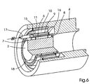
- the spacer 8 encloses the pinch roller overrunning clutch 5 peripherally and axially towards the housing. The other end of the spacer 8 is radially outward extended so that it forms a closure flange 12.
- the closure flange 12 is supported from a bearing seal 13, which the cam roller arm 2 and the shaft 3 against Bearing arrangement seals.
- a lubricant injection opening 14 makes this possible Injecting lubricant into the bearing assembly through the housing 4.
- the outer Rolling bearing is held in position by retaining rings 15 and 16.
- index function no longer takes over the inner roller bearing, but one spring-loaded index pin 17.
- the spacer 8 has index grooves 18 on its end face on.
- the index pin 17 is fastened in the cam roller arm 2. When the Cam roller arm 2, index pin 17 slides forward by at least one index groove 18, while the bearing seal 8 remains stationary. If the cam roller arm 2 in the Swinging backward movement holds one of the steep ramps of the index grooves 18 den Index pin 17 fixed. In this way, the spacer 8 is forced to To follow the downward movement of the cam roller arm 2.
- This index function has the same Effect like the pinch roller clutch shown in Figs. 3 and 4.
- the index direction of the index pin 17 that functionally interacts with the index grooves 18 can be determined by the ramps. Flat ramps in the forward direction and in the In the opposite direction, steeply rising edges cause the spacer 8 is moved with the downward movement. Conversely, sharply rising edges in An index movement with the forward direction and flat ramps in the backward direction Upward movement.
- the amount of locking force is also above the spring force of the pin 17 against the grooves 18 biasing spring and the inclination of the grooves 18 adjustable.
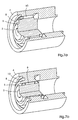
- FIGS. 7A and 7B it can be clearly seen that the torque is also via the Housing 4 can be transmitted while the shaft 3 with respect to the machine frame is stationary.
- the functional units remain unchanged.
Landscapes
- Engineering & Computer Science (AREA)
- General Engineering & Computer Science (AREA)
- Mechanical Engineering (AREA)
- Rolls And Other Rotary Bodies (AREA)
- Rolling Contact Bearings (AREA)
- Rotary Presses (AREA)
- Folding Of Thin Sheet-Like Materials, Special Discharging Devices, And Others (AREA)
Abstract
Description
- Fig. 1A bis 1D
- vier schematische, axiale Seitenansichten aufeinanderfolgender Lagerstellungen der erfindungsgemäßen Lageranordnung;
- Fig. 2
- eine schematische, axiale Seitenansicht der Lageranordnung;
- Fig. 3
- eine axiale Schnittansicht einer ersten Ausführungsform der Lageranordnung, bei der die Umgebungsstruktur gestrichelt dargestellt ist;
- Fig. 4
- eine teilweise, perspektivische Schnittansicht der ersten Ausführungsform der Lageranordnung;
- Fig. 5
- eine axiale Schnittansicht einer zweiten Ausführungsform der Lageranordnung;
- Fig. 6
- eine teilweise, perspektivische Schnittansicht der zweiten Ausführungsform der Lageranordnung;
- Fig. 7A und 7B
- teilweise, schematische, perspektivische Schnittansichten der Lageranordnung, die den Funktionszusammenhang der verschiedenen Teile in der Vorwärts- und Rückwärtsbewegung der Schwingbewegung darstellen.

- 1
- Kurvenrolle
- 2
- Kurvenrollenarm
- 3
- Welle
- 4
- ortsfestes Gehäuse
- 5
- Klemmrollen-Freilaufkupplung
- 6
- Rollkörper
- 7
- äußere Hülse
- 8
- Abstandhalter
- 9
- innere Hülse
- 10
- Rollen
- 11
- äußere Hülse
- 12
- Verschlussflansch
- 13
- Lagerdichtung
- 14
- Schmiermittel-Einspritzöffnung
- 15
- Haltering
- 16
- Haltering
- 17
- Indexstift
- 18
- Indexrillen
Claims (9)
- Vorrichtung zum Lagern eines Schwenkelements (2), insbesondere eines Kurvenabtaster-Arms in einer Rollenrotationsdruckmaschine, mit einem ortsfesten Element (4) und einer an diesem befestigten Lageranordnung, in der das Schwenkelement (2) relativ gegen das ortsfeste Element (4) derart schwenkbar gelagen ist, dass das Schwenkelement (2) in Vorwärtsrichtung in eine erste Endlage und in Rückwärtsrichtung in eine zweite Endlage bewegbar ist,
dadurch gekennzeichnet,
dass die Lageranordnung ein an dem Schwenkelement (2) befestigtes erstes Wälzlager und ein zwischen dem ersten Wälzlager und dem ortsfesten Element (4) angeordnetes zweites Wälzlager umfasst, von denen eines mit dem Schwenkelement (2) in Vorwärtsrichtung drehbar ist, während es in Rückwärtsrichtung an einer Drehung gehindert wird. - Vorrichtung nach Anspruch 1,
dadurch gekennzeichnet,
dass das ortsfeste Element (4) als ein ortsfestes Gehäuse und das Schwenkelement (2) als eine über die Lageranordnung an das Gehäuse (4) angelenkte schwenkbare Welle ausgebildet sind. - Vorrichtung nach einem der vorhergehenden Ansprüche,
dadurch gekennzeichnet,
dass ferner ein zwischen dem ersten Wälzlager und dem zweiten Wälzlager angeordneter Abstandhalter (8) vorgesehen ist. - Vorrichtung nach einem der vorhergehenden Ansprüche,
dadurch gekennzeichnet,
dass das erste Wälzlager als eine Klemmkörper-Freilaufkupplung (5) ausgebildet ist, die in Vorwärtsrichtung drehbar und in Rückwärtsrichtung an einer Drehung gehindert wird. - Vorrichtung nach einem der Ansprüche 1 bis 3,
dadurch gekennzeichnet,
dass an der Stirnseite des Abstandhalters (8) Indexrillen (18) vorgesehen sind und dass an dem Schwenkelement (2) ferner ein Indexstift (17) vorgesehen ist, der federkraftbeaufschlagt gegen die Indexrillen (18) der Stirnseite angestellt oder anstellbar ist. - Vorrichtung nach einem der vorhergehenden Ansprüche,
dadurch gekennzeichnet,
dass das erste Wälzlager mit der Achswelle (3) zwischen der ersten und zweiten Endlage schwenkbar ist oder geschwenkt wird, während das zweite Wälzlager nur in eine der beiden Richtungen schrittweise bewegbar ist oder bewegt wird. - Vorrichtung nach Anspruch 6,
dadurch gekennzeichnet,
dass das zweite Wälzlager bezüglich des ortsfesten Elements (4) nur in Vorwärtsrichtung schrittweise bewegbar ist oder bewegt wird. - Vorrichtung nach Anspruch 6,
dadurch gekennzeichnet,
dass das zweite Wälzlager bezüglich des ortsfesten Elements (4) nur in Rückwärtsrichtung schrittweise bewegbar ist oder bewegt wird. - Druckmaschine,
gekennzeichnet durch
eine Vorrichtung zum Lagern eines Schwenkelements (2) nach einem der vorhergehenden Ansprüche.
Applications Claiming Priority (2)
| Application Number | Priority Date | Filing Date | Title |
|---|---|---|---|
| US30617699A | 1999-05-06 | 1999-05-06 | |
| US306176 | 1999-05-06 |
Publications (2)
| Publication Number | Publication Date |
|---|---|
| EP1050694A2 true EP1050694A2 (de) | 2000-11-08 |
| EP1050694A3 EP1050694A3 (de) | 2002-06-19 |
Family
ID=23184168
Family Applications (1)
| Application Number | Title | Priority Date | Filing Date |
|---|---|---|---|
| EP00109009A Withdrawn EP1050694A3 (de) | 1999-05-06 | 2000-04-26 | Vorrichtung zum Lagern eines Schwenkelements |
Country Status (3)
| Country | Link |
|---|---|
| EP (1) | EP1050694A3 (de) |
| JP (1) | JP2000320549A (de) |
| DE (1) | DE10020317A1 (de) |
Families Citing this family (1)
| Publication number | Priority date | Publication date | Assignee | Title |
|---|---|---|---|---|
| CN105264380B (zh) | 2013-05-14 | 2017-09-05 | 卫材R&D管理有限公司 | 用于预测和评价子宫内膜癌受试者对乐伐替尼化合物响应性的生物标志 |
Family Cites Families (7)
| Publication number | Priority date | Publication date | Assignee | Title |
|---|---|---|---|---|
| US1574470A (en) * | 1923-08-03 | 1926-02-23 | Safety Car Heating & Lighting | Bearing construction |
| DE845434C (de) * | 1950-10-29 | 1952-07-31 | Deutsche Bundesbahn | Waelzlager, insbesondere Nadellager |
| US2647807A (en) * | 1951-06-30 | 1953-08-04 | Standard Oil Co | Nonfretting antifriction bearing |
| DE954928C (de) * | 1954-09-10 | 1956-12-27 | Gerhard Hagedorn | In zwei oder mehrere Teillager aufgeteiltes Waelzlager der Radial- oder Axialbauart |
| US3025114A (en) * | 1960-02-29 | 1962-03-13 | Gen Motors Corp | Antifriction bearings |
| DE3533316A1 (de) * | 1985-09-18 | 1987-03-26 | Siemens Ag | Spielfreie lageranordnung fuer ein oszillierend angetriebenes drehteil |
| DE19626959A1 (de) * | 1996-07-04 | 1998-01-08 | Schaeffler Waelzlager Kg | Mit einem Wälzlager kombinierter Klemmrollenfreilauf |
-
2000
- 2000-04-26 EP EP00109009A patent/EP1050694A3/de not_active Withdrawn
- 2000-04-26 DE DE10020317A patent/DE10020317A1/de not_active Withdrawn
- 2000-05-01 JP JP2000132557A patent/JP2000320549A/ja active Pending
Also Published As
| Publication number | Publication date |
|---|---|
| EP1050694A3 (de) | 2002-06-19 |
| JP2000320549A (ja) | 2000-11-24 |
| DE10020317A1 (de) | 2000-12-14 |
Similar Documents
| Publication | Publication Date | Title |
|---|---|---|
| DE60115368T2 (de) | Nockenvorrichtung | |
| DE10122434A1 (de) | Elektrische Servolenkvorrichtung | |
| DE2136243A1 (de) | Stufenlos verstellbares Getriebe | |
| DE102011101131A1 (de) | Getriebe zur Übertragung eines Drehmoments | |
| DD209237A5 (de) | Vorrichtung zur umwandlung einer rotierenden in eine lineare bewegung | |
| DE60116130T2 (de) | Tripode-gleichlaufgelenk | |
| DE3021605C2 (de) | ||
| DE102020109646B4 (de) | Drehlager und Getriebebox | |
| DE69611126T2 (de) | Zweirichtungs-Differentialkupplung | |
| DE3018883C2 (de) | Vorrichtung zur axialen Lagesicherung zwischen einem Hohlrad und den Planetenrädern eines Planetengetriebes | |
| DE4430625B4 (de) | Lagereinheit für eine Walzenanordnung | |
| EP0475119B1 (de) | Vorrichtung für das Übertragen von Druckfarbe in einer Druckmaschine | |
| DE2332549A1 (de) | Umlenkeinrichtung | |
| DE19741520A1 (de) | Vorrichtung zum Ausrichten gekerbter Wafer | |
| DE2938869C2 (de) | Durchbiegungseinstellwalze | |
| CH666704A5 (de) | Rotations-schaftmaschine. | |
| DE10020317A1 (de) | Vorrichtung zum Lagern eines Schwenkelements | |
| DE2348784C3 (de) | Überlastsicherung für die Antriebsteile an einer Aufsammelballenpresse für landwirtschaftliche Erntegüter | |
| DE102007058248A1 (de) | Übertragungstrommel zwischen Druckwerken einer Bogendruckmaschine | |
| DE3206704C2 (de) | Entnahme- und Übergabevorrichtung für Etiketten oder dergl. | |
| DE602005002391T2 (de) | Schwenkbarer Drehtisch | |
| DE2818972A1 (de) | Universalgelenk zum antriebsmaessigen verbinden von zwei rotierenden teilen | |
| EP0709637A1 (de) | Laufrollenlagerung | |
| DE10136785C2 (de) | Rotationsverzögerungsvorrichtung | |
| DE19602770C2 (de) | Kolbenrollen-Führung für Radialkolbenaggregat |
Legal Events
| Date | Code | Title | Description |
|---|---|---|---|
| PUAI | Public reference made under article 153(3) epc to a published international application that has entered the european phase |
Free format text: ORIGINAL CODE: 0009012 |
|
| AK | Designated contracting states |
Kind code of ref document: A2 Designated state(s): AT BE CH CY DE DK ES FI FR GB GR IE IT LI LU MC NL PT SE |
|
| AX | Request for extension of the european patent |
Free format text: AL;LT;LV;MK;RO;SI |
|
| PUAL | Search report despatched |
Free format text: ORIGINAL CODE: 0009013 |
|
| AK | Designated contracting states |
Kind code of ref document: A3 Designated state(s): AT BE CH CY DE DK ES FI FR GB GR IE IT LI LU MC NL PT SE |
|
| AX | Request for extension of the european patent |
Free format text: AL;LT;LV;MK;RO;SI |
|
| RIC1 | Information provided on ipc code assigned before grant |
Free format text: 7F 16C 19/55 A, 7B 41F 13/20 B |
|
| AKX | Designation fees paid | ||
| REG | Reference to a national code |
Ref country code: DE Ref legal event code: 8566 |
|
| STAA | Information on the status of an ep patent application or granted ep patent |
Free format text: STATUS: THE APPLICATION IS DEEMED TO BE WITHDRAWN |
|
| 18D | Application deemed to be withdrawn |
Effective date: 20021220 |