EP1049316A2 - Image reading apparatus and image forming apparatus - Google Patents

Image reading apparatus and image forming apparatus Download PDF

Info

Publication number
EP1049316A2
EP1049316A2 EP00108842A EP00108842A EP1049316A2 EP 1049316 A2 EP1049316 A2 EP 1049316A2 EP 00108842 A EP00108842 A EP 00108842A EP 00108842 A EP00108842 A EP 00108842A EP 1049316 A2 EP1049316 A2 EP 1049316A2
Authority
EP
European Patent Office
Prior art keywords
original document
conveying
image
reading
route
Prior art date
Legal status (The legal status is an assumption and is not a legal conclusion. Google has not performed a legal analysis and makes no representation as to the accuracy of the status listed.)
Withdrawn
Application number
EP00108842A
Other languages
German (de)
French (fr)
Other versions
EP1049316A3 (en
Inventor
Kazuhiko Hasegawa
Norio Kajiwara
Toshiyuki Takano
Yoshiyuki Nakayama
Tsuyoshi Yoshida
Current Assignee (The listed assignees may be inaccurate. Google has not performed a legal analysis and makes no representation or warranty as to the accuracy of the list.)
Canon Inc
Original Assignee
Canon Inc
Priority date (The priority date is an assumption and is not a legal conclusion. Google has not performed a legal analysis and makes no representation as to the accuracy of the date listed.)
Filing date
Publication date
Priority claimed from JP11799499A external-priority patent/JP3408190B2/en
Priority claimed from JP13533599A external-priority patent/JP3517607B2/en
Priority claimed from JP13533699A external-priority patent/JP3372893B2/en
Priority claimed from JP11154107A external-priority patent/JP2000344384A/en
Priority claimed from JP2000053771A external-priority patent/JP2001245105A/en
Application filed by Canon Inc filed Critical Canon Inc
Publication of EP1049316A2 publication Critical patent/EP1049316A2/en
Publication of EP1049316A3 publication Critical patent/EP1049316A3/en
Withdrawn legal-status Critical Current

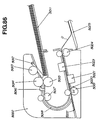
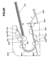
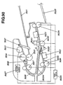
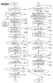
Links

Images

Classifications

    • HELECTRICITY
    • H04ELECTRIC COMMUNICATION TECHNIQUE
    • H04NPICTORIAL COMMUNICATION, e.g. TELEVISION
    • H04N1/00Scanning, transmission or reproduction of documents or the like, e.g. facsimile transmission; Details thereof
    • H04N1/00567Handling of original or reproduction media, e.g. cutting, separating, stacking
    • H04N1/0057Conveying sheets before or after scanning
    • H04N1/00572Conveying sheets before or after scanning with refeeding for double-sided scanning, e.g. using one scanning head for both sides of a sheet
    • H04N1/00575Inverting the sheet prior to refeeding
    • H04N1/0058Inverting the sheet prior to refeeding using at least one dead-end path, e.g. using a sheet ejection path
    • HELECTRICITY
    • H04ELECTRIC COMMUNICATION TECHNIQUE
    • H04NPICTORIAL COMMUNICATION, e.g. TELEVISION
    • H04N1/00Scanning, transmission or reproduction of documents or the like, e.g. facsimile transmission; Details thereof
    • H04N1/00567Handling of original or reproduction media, e.g. cutting, separating, stacking
    • H04N1/0057Conveying sheets before or after scanning
    • H04N1/00572Conveying sheets before or after scanning with refeeding for double-sided scanning, e.g. using one scanning head for both sides of a sheet
    • HELECTRICITY
    • H04ELECTRIC COMMUNICATION TECHNIQUE
    • H04NPICTORIAL COMMUNICATION, e.g. TELEVISION
    • H04N1/00Scanning, transmission or reproduction of documents or the like, e.g. facsimile transmission; Details thereof
    • H04N1/04Scanning arrangements, i.e. arrangements for the displacement of active reading or reproducing elements relative to the original or reproducing medium, or vice versa
    • H04N1/12Scanning arrangements, i.e. arrangements for the displacement of active reading or reproducing elements relative to the original or reproducing medium, or vice versa using the sheet-feed movement or the medium-advance or the drum-rotation movement as the slow scanning component, e.g. arrangements for the main-scanning
    • HELECTRICITY
    • H04ELECTRIC COMMUNICATION TECHNIQUE
    • H04NPICTORIAL COMMUNICATION, e.g. TELEVISION
    • H04N1/00Scanning, transmission or reproduction of documents or the like, e.g. facsimile transmission; Details thereof
    • H04N1/04Scanning arrangements, i.e. arrangements for the displacement of active reading or reproducing elements relative to the original or reproducing medium, or vice versa
    • H04N1/19Scanning arrangements, i.e. arrangements for the displacement of active reading or reproducing elements relative to the original or reproducing medium, or vice versa using multi-element arrays
    • H04N1/191Scanning arrangements, i.e. arrangements for the displacement of active reading or reproducing elements relative to the original or reproducing medium, or vice versa using multi-element arrays the array comprising a one-dimensional [1D] array
    • H04N1/192Simultaneously or substantially simultaneously scanning picture elements on one main scanning line
    • H04N1/193Simultaneously or substantially simultaneously scanning picture elements on one main scanning line using electrically scanned linear arrays, e.g. linear CCD arrays

Definitions

  • the present invention relates to a double-sided image reading apparatus and to an image forming apparatus, such as an image copying apparatus, a facsimile machine, or a composite apparatus combining the above, utilizing the double-sided image reading apparatus.
  • Japanese Unexamined Patent Heisei No. 1-126870 (second prior art), a structure having two image reading means opposing each other which sandwich an original document pressing roller for reading respectively each side of an original document by switching back the original document is suggested.
  • the two image reading means require two image processing means, thereby increasing the production cost.
  • an apparatus for one-sided reading as a standard configuration which optionally has a double-sided reading function is to be developed, even the standard configuration having a one-sided reading function requires two image processing means beforehand, resulting in that cost advantage provided by an apparatus having only a one-sided reading function becomes less.
  • an original document returned by switching back is to be read from the rear end of the sheet, which causes the image information to be sent upside down page by page when, for example, the information is sent as FAX images.
  • a means for reversing the up or down side of an image or a conveying means for reversing the up or down side of an image is required, thus making the apparatus structure complicated.
  • an object of the present invention to provide an image reading apparatus and an image forming apparatus which are excellent without defects, and more specifically to achieve miniaturization and cost lowering of an image reading apparatus and an image forming apparatus mounting the image reading apparatus.
  • an object of the present invention to provide an image reading apparatus and an image forming apparatus capable of reading good images while improving an operating efficiency of the reading process of the original documents by differentiating the conveying speeds between the original document conveying means.
  • a representative structure of a double-sided image reading apparatus is to structure an original document conveying route, an original document conveying means for conveying an original document along the original document conveying route, a first reading means for reading an image on one side of the original document, and a second reading means for reading an image on the other side of the original document, where an image on one side of an original document is read at the first reading means while the original document is forwardly conveyed by the original document conveying means and then after convey in a reverse direction, the other side of the original document is read at the second reading means while conveyed forwardly again.
  • the image reading apparatus of the same as the mentioned above can form a branching conveying route branching off from the original document conveying route at an upstream side, in the conveying direction, of at least one of the image reading means, the branching conveying route capable of guiding the original document conveyed by the original document conveying means.
  • the above-mentioned image reading apparatus has, in addition to the original document conveying route, another branching conveying route for making the original document conveyed in the reverse direction temporarily escape, the original document can escape smoothly even if the original document conveying route has a U-turn shape.
  • the image reading apparatus might include an original document conveying route having at least a partial curvature section to have a U-turn shaped portion and a reverse path branching off from a midway point on the original document conveying route, the reverse path having at least a partial curvature section to have a U-turn shaped portion.
  • the original document when conveyed in a reverse direction for escape, the original document is returned on an original document mounting tray serving as an original document feeding means, thereby making an apparatus installation space smaller.
  • an image reading apparatus includes an original document feeding means for feeding stacked original documents, an original document conveying route for conveying the original documents fed from the original document feeding means, at least one image forming means placed in a midway point on the original document conveying route, and a plurality of original document conveying means for conveying the original documents in the original document conveying route, each of the original document conveying means having a document conveying speed different from that of at least one side of adjacent original document conveying means.
  • an original document processing efficiency can be improved as a whole in the original document conveying route and also a degree of tension and a degree of flexion of the original documents can be controlled between the plural original document conveying means, and therefore the image reading means can read good images.
  • Fig. 1 is a cross-sectional view showing a double-sided image reading apparatus according to the invention.
  • Fig. 2 is a perspective view showing an exterior appearance of the double-sided image reading apparatus.
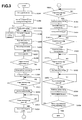
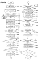
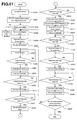
  • Fig. 3 is a flow chart showing an operation of the double-sided image reading apparatus.
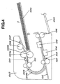
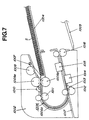
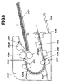
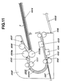
  • Fig. 4 to Fig. 13 are illustrations showing operations of the double-sided image reading apparatus.
  • a facsimile machine used as the double-sided image reading apparatus is described.
  • a main body 1001 of the facsimile machine shown in Fig. 2 forms, on its upper portion, an image reading section 1002 utilizing the double-sided image reading apparatus of the invention and, on its lower portion, an image forming section 1003.
  • the image reading section 1002 has an original document tray 1004 for stacking original documents to be read and a delivering tray 1005 for discharging and stacking the original documents where reading operation is completed.
  • a conveying route 1006 is provided so as to form a U-turn shape leading from the original document tray 1004 to the delivering tray 1005.
  • an original document existing-nonexisting sensor 1007 On an upstream side of the U-turn portion 1006a of the conveying route 1006, there are provided an original document existing-nonexisting sensor 1007, a pickup roller 1008 for feeding stacked original documents, a separating roller 1009a and a reverse roller 1009b working in cooperation with each other to separate and feed the original documents, an original document feeding sensor 1010 for detecting a front end and rear end of the separated original document, and a conveying roller 1011 serving as an original document conveying means for conveying the separated original documents to the U-turn portion 1006a.
  • a front surface reading section 1014 serving as the first reading means composed of a pressing type image sensor, a forwardingly-reversingly rotatable pair of conveying rollers 1012 for conveying the original documents to the front surface reading section 1014, an original document edge sensor 1013 for determining the timing of starting and finishing of the reading operation of the original documents, a back surface reading section 1015 serving as the second reading means composed of a pressing type image sensor, and a forwardingly-reversingly rotatable pair of delivering rollers 1016 for delivering the original documents to the delivering tray 1005.
  • a reverse path 1017 serving as a bypath means during reversing operation is provided to be structured so that the original documents are not returned to an upstream side of the U-turn portion 1006a.
  • a drive motor 1018 is provided in the image reading section 1002, transferring the driving to the pickup roller 1008, the separating roller 1009a, the reverse roller 1009b, the conveying roller pair 1011, 1012, and the delivering roller pair 1016. Furthermore, the driving is transferred via an electromagnetic clutch 1019 to the pickup roller 1008, the separating roller 1009a, and the reverse roller 1009b, making it possible to block temporarily the driving transference.
  • a user sets original documents S on the original document tray 1004 (S1001), and then the original documents S are detected by the original document existing-nonexisting sensor 1007 (S1002, Fig. 4).
  • the image reading process starts where the electromagnetic clutch 1019 is connected to provide the driving force to the pickup roller 1008, the separating roller 1009a, and the reverse roller 1009b (S1004).
  • the drive motor 1018 rotates in a forward direction (S1005), and the pickup roller 1008 directly contacts with the original documents to send them to the internal of the apparatus (S1006).
  • the original documents are separated sheet by sheet by means of the separating roller 1009a and the reverse roller 1009b, and only an uppermost sheet of the original document S is conveyed (S1007).
  • the pickup roller 1008 When the original document feeding sensor 1010 detects the front end of the original document (S1008), the pickup roller 1008 is withdrawn from the original documents S to be released from the feeding operation (S1009, Fig. 6). Then, the separated original document S is conveyed to the U-turn portion 1006a by the conveying roller pair 1011 (S1010). After passing the U-turn portion 1006a, the original document is conveyed by the conveying roller pair 1012, and then after the front end of the original document is detected by the original document edge sensor 1013 (S1011), the front surface reading section 1014 starts reading the front surface of the original document at the place where the paper is conveyed by a predetermined amount from the detected place 1013 (S1012, Fig. 7).
  • the electromagnetic clutch 1019 blocks the driving of the pickup roller 1008, the separating roller 1009a, and the reverse roller 1009b, so the following documents stop without being conveyed (S1014, Fig. 8).
  • the front surface reading section 1014 finishes reading the front surface of the original document at the place where the paper is conveyed by a predetermined amount from the detected place (S1016, Fig. 9).
  • the drive motor 1018 is rotationally driven in a reverse direction (S1017), and consequently the original document S is conveyed in a reverse direction by the conveying roller pair 1012 and the delivering roller pair 1016, and further conveyed to the reverse path by means of the shape of the intersecting portion of the U-turn portion 1006a and the reverse path 1017 (S1018, Fig. 10).
  • the reverse path 1017 is provided lower than as well as straightly with respect to the conveying route 1006 which is downstream of the U-turn portion 1006a, the original document thus to be reversely conveyed is naturally led to the reverse path 1017 with its own weight.
  • the original document edge sensor 1013 detects the end of the original document (S1019, Fig.
  • the drive motor 1018 again rotates in a forward direction (S1020).
  • the original document edge sensor 1013 again detects the front end of the original document (S1021)
  • the back surface reading section 1015 starts reading the back surface of the original document at the place where the original document is conveyed by a predetermined amount from the detected place (S1022, Fig. 12).
  • the back surface reading section 1015 finishes reading the back surface of the original document at the place where the original document is conveyed by a predetermined amount from the detected place (S1024), and then the delivering roller pair 1016 delivers and mounts the original document on the delivering tray 1005 (S1025, Fig. 13).
  • the original document existing-nonexisting sensor 1007 detects original documents, the following original document is conveyed by going back to Step 1004; when the sensor does not detect any documents, reading operation is completed (S1026).
  • the structure as mentioned above can sequentially send the image information read from the both sides of the original document to single image processing means, so a plurality of the image processing means are not required, thereby making it possible to simplify the circuit and miniaturize the base board and also achieving reduction of the production costs.
  • the apparatus can start reading from the front end of the original document in the both cases of the front surface and back surface (both sides) reading operation, so an image processing means or an original document reverse means used for reversing the image data is not needed.
  • an image processing means or an original document reverse means used for reversing the image data is not needed.
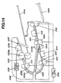
  • FIG. 14 is a cross-sectional view showing an image reading apparatus of the second embodiment
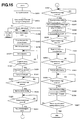
  • Fig. 15 is a flow chart showing an operation of the image reading apparatus
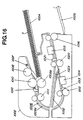
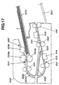
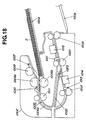
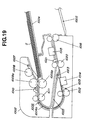
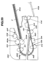
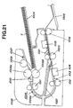
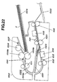
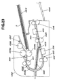
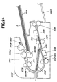
  • Fig. 16 to Fig. 25 are illustrations showing operations of the image reading apparatus.
  • the redundant part of the description mentioned in the first embodiment will be omitted by providing the same symbols.
  • the present embodiment has a bypath means which structure is different from that of the first embodiment as mentioned above.
  • a forwardingly-reversingly rotatable conveying roller pair 1020 is attached upstream of the back surface reading section 1015, and attached downstream of the conveying roller pair 1020 is an original document edge sensor 1021 for detecting a front end and rear end of original documents in order to determine the timing of starting and finishing of the back surface reading operation by the back surface reading section 1015.
  • a reverse path communicating from the conveying roller pair 1020 to the outside of the apparatus is provided to be so structured as to prevent the original document S from passing on the front surface reading section 1014 when conveyed in a reverse direction.
  • a conveying route switching flapper 1023 is provided at an intersecting portion of the reverse path 1022 and the conveying route 1006 for conveying the original document S in a forward direction (Arrow P direction) by opening the conveying route 1006 or for leading the original document S in a reverse direction (Arrow Q direction) by shutting down the conveying route 1006, thus to lead the original document S to the reverse path 1022.
  • a user sets original documents S on the original document tray 1004 (S1031), and then the original documents S are detected by the original document existing-nonexisting sensor 1007 (S10032, Fig. 16).
  • the image reading process starts where the electromagnetic clutch 1019 is connected to provide the driving force to the pickup roller 1008, the separating roller 1009a, and the reverse roller 1009b (S1034).
  • the drive motor 1018 rotates in a forward direction (S1035), and the pickup roller 1008 directly contacts with the original documents to send them to the internal of the apparatus (S1036).
  • the original documents are separated sheet by sheet by means of the separating roller 1009a and the reverse roller 1009b, and only an uppermost sheet of the original document S is conveyed (S1037, Fig. 17).
  • the pickup roller 1008 When the original document feeding sensor 1010 detects the front end of the original document (S1038), the pickup roller 1008 is withdrawn from the original documents S to be released from the feeding operation (S1039, Fig. 18). Then, the original document S thus separated is conveyed to the U-turn portion 1006a by the conveying roller pair 1011 (S1040). After passing the U-turn portion 1006a, the original document is conveyed by the conveying roller pair 1012, and then after the front end of the original document is detected by the original document edge sensor 1013 (S1041), the front surface reading section 1014 starts reading the front surface of the original document at the place where the paper is conveyed by a predetermined amount from the detected place (S1042, Fig. 19).
  • the electromagnetic clutch 1019 blocks the driving of the pickup roller 1008, the separating roller 1009a, and the reverse roller 1009b, so the following documents stop without being conveyed (S1044, Fig. 20).
  • the front surface reading section 1014 finishes reading the front surface of the original document at the place where the paper is conveyed by a predetermined amount from the detected place (S1046, Fig. 21).
  • the original document S is conveyed further downstream by the conveying roller pair 1020, and when the rear end of the original document passes the conveying route switching flapper 1023 (S1047), the drive motor 1018 rotates in a reverse direction (S1048). Subsequently, the original document S is conveyed in a reverse direction by the conveying roller pair 1020 and the delivering roller pair 1016 and led to the reverse path 1022 by the conveying route switching flapper 1023 (S1049, Fig. 22).
  • the drive motor 1018 again rotates in a forward direction (S1051).
  • the back surface reading section 1015 starts reading the back surface of the original document at the place where the original document is conveyed by a predetermined amount from the detected place (S1049, Fig. 24).
  • the back surface reading section 1015 finishes reading the back surface of the original document at the place where the original document is conveyed by a predetermined amount from the detected place (S1055), and then the delivering roller pair 1016 delivers and mounts the original document on the delivering tray 1005 (S1056, Fig. 25).
  • the original document existing-nonexisting sensor 1007 detects original documents, the operation is returned to S1034 where following original documents are conveyed; when the sensor does not detect any documents, reading operation is completed (S1057).
  • the structure as mentioned above can sequentially send the image information read from the both sides of the original document to single image processing means, so a plurality of the image processing means are not required, thereby making it possible to simplify the circuit and miniaturize the base board and also achieving reduction of the production costs.
  • the apparatus can start reading from the front end of the original document in the both cases of the front surface and back surface (both sides) reading operation, so an image processing means or an original document reverse means used for reversing the image data is not needed.
  • an image processing means or an original document reverse means used for reversing the image data is not needed.
  • An image reading apparatus will hereinafter be described with reference to Fig. 26 to Fig. 38.
  • a structure of an image reading apparatus in a facsimile machine is explained by way of example.
  • Fig. 27 is a perspective view showing an exterior appearance of a facsimile machine.
  • numeral 2001 refers to a main body of the machine
  • numeral 2002 refers to an image reading section according to the invention arranged in an upper portion of the machine main body 2001
  • numeral 2003 refers to an image forming section arranged in a lower portion of the machine main body 2001
  • numeral 2011 refers to an original document mounting tray structured so as to stack a plural of original documents D
  • numeral 2025 refers to a sheet delivering tray.
  • Fig. 26 is a typified cross-sectional view showing a schematic structure of the image reading section in the facsimile machine.
  • numeral 2012 is an original document existing-nonexisting detecting sensor for detecting whether or not original documents D are set on the original document mounting tray 2004
  • numeral 2013 is a pickup roller for feeding the original documents D thus set to the internal of the image reading section 2002
  • numeral 14 and 15 are respectively a separating roller and a reverse roller working in cooperation with each other for separating a plural number of the original documents D and for feeding the separated sheet of the original documents
  • numeral 2016 is an original document feeding sensor for detecting a front end or rear end of the separated original document D
  • numeral 2017 is a conveying roller pair for conveying the separated original document D to a U-turn path 2018 which is a U-turn shaped conveying route
  • numeral 2019 is a conveying roller pair for conveying the original document D after performing U-turn to a front surface reading section 2021 composed of a pressing type image sensor
  • the above-mentioned conveying route switching flapper 2033 is freely rotatably attached at the branching portion of the reverse path 2034 which branches off from the U-turn path 2018 on an upstream side of the back surface reading section 2023 serving as a reading means provided on a downstream side in the conveying direction.
  • the conveying route switching flapper 2036 is freely rotatably attached at the intersecting portion of the U-turn path 2018 and the reverse path 2034, the intersecting portion locating on a downstream side, in the conveying direction, of the conveying roller pair 2017 as well as on an upstream side, in the conveying direction, of the branching portion as mentioned above.
  • the conveying route switching flappers 2033 and 2036 are so structured as to move rotationally by the original document conveyed in a forward direction in the U-turn path 2018 to open the path 2018, functioning as a guide for the path 2018 at the branching portion with or the intersecting portion with the reverse path 2034.
  • conveying route switching flappers 2033 and 2036 are so constructed as to move rotationally by passage of the rear end of the original document, thereby shutting down the path 2018 to move to a position which leads the original document to the reverse path 2034, functioning as a guide for the reverse path 2034 at the branching portion or the intersecting portion of the U-turn path 2018 and the reverse path 2034.
  • the image reading section 2002 is so structured as to be suitably controlled by the controlling circuit (controlling means) although not shown in the figures; for example, those are controlled such as an image processing circuit (image processing means) for processing the image information of the original document D read by the front surface reading section 2021 and the back surface reading section 2023 and a switching circuit (switching means) for switching, as an inputting source of the image information, to the front surface reading section 2021 or to the back surface reading section 2023.
  • the controlling circuit controlling means
  • switching means switching means for switching, as an inputting source of the image information
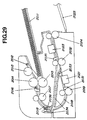
  • the original document existing-nonexisting detecting sensor 2012 detects the original documents (See, S2002, Fig. 29).
  • the user selects a double-sided reading mode, and then directs to start reading operation (S2003).
  • start reading operation S2003.
  • one-sided reading mode the operation is switched to the conventionally known one-sided reading operation (detailed description omitted).
  • the electromagnetic clutch 2027 After receiving the direction for starting reading operation, the electromagnetic clutch 2027 connects the driving for the pickup roller 2013, the separating roller 2014, and the reverse roller 2015 (S2004).
  • the drive motor 2026 rotates in a forward direction (S2005), and then the pickup roller 2013 directly presses the original documents D set on the original document mounting tray 2011 to start picking-up conveyance of the original document D into the inside of the apparatus (S2006).
  • the original documents D after picking-up conveyance are to be separated by the separating roller 2014 and the reverse roller 2015, and an uppermost sheet of the original documents is fed in a separating way (See, S2007, Fig. 30).
  • the original document D thus conveyed to this U-turn path 2018 makes the conveying route switching flapper 2036 move rotationally, thus to open the U-turn path 2018.
  • the conveying route switching flapper 2036 thus moving rotationally has a shape smoothly connecting to the U-turn path 2018, thereby preventing the rear end of the original document from flapping at a space where the U-turn path 2018 intersects with the reverse path 2034.
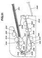
  • the original document D is conveyed by the conveying roller pair 2019, and the front end of the original document D is detected by the original document edge sensor 2031 (S2011). Then, at the place where the original document is conveyed by a predetermined amount from the detected place, the front surface reading section 2021 starts reading the front surface of the original document (See, S2012, Fig. 32).
  • the electromagnetic clutch 2027 blocks the driving for the pickup roller 2013, the separating roller 2014, and the reverse roller 2015, and consequently the following original document is to be stopped without being conveyed (See, S2014, Fig. 33).
  • the conveying route switching flapper 2036 moves rotationally to shut down the U-turn path 2018, and then moves to the position for leading the original document D to the reverse path 2034.
  • the conveying route switching flapper 2036 can prevent the original document from entering to the U-turn path 2018 by mistake because it functions as a guide for the reverse path 2034 as well, and therefore, stable conveying performance can be gained.
  • the front surface reading section 2021 finishes reading operation of the front surface of the original document at a place where the original document is conveyed by a predetermined amount from the detected place (S2016).
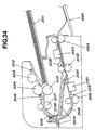
  • the original document D is conveyed by the conveying roller pair 2032 to the further downstream side, and when the rear end of the original document passes the conveying route switching flapper 2033 (See, S2017, Fig. 34), the drive motor 2026 rotates in a reverse direction (S2018).
  • the original document D is conveyed in a reverse direction by the conveying roller pair 2032 and the sheet delivering roller pair 2024 and led to the reverse path 2034 by the conveying route switching flapper 2033 (See, S2019, Fig. 35).
  • the drive motor 2026 rotates again in a forward direction (See, S2021, Fig. 36).
  • the original document edge sensor 2035 detects the front end of the original document D (S2022), and at a place where the original document is conveyed by a predetermined amount from the detected place, the back surface reading section 2023 starts reading operation of the back surface of the original document (See, S2023, Fig. 37).
  • the original document edge sensor 2035 detects the rear end of the original document D (S2024), and at a place where the original document is conveyed by a predetermined amount from the detected place, the back surface reading section 2023 finishes reading operation of the back surface of the original document (S2025). Then, the original document D is delivered by the sheet delivering roller pair 2024 onto the sheet delivering tray 2025 (See, S2026, Fig. 38).
  • Step S2004 When the original document existing-nonexisting detecting sensor 2012 detects original documents D, operation is returned to Step S2004, as mentioned above, where the electromagnetic clutch 2027 connects the driving for the pickup roller 2013, the separating roller 2014, and the reverse roller 2015, thereby conveying the following original documents; if the sensor 2012 detects no documents, reading operation is completed (S2027).
  • respective image information can be sequentially sent to single image processing means by switching two reading means (front surface reading section 2021 and back surface reading section 2023), and therefore a plural number of the image processing means are not required, and also simplification of the electric circuit as well as miniaturization of the base board can be achieved, thereby lowering the cost.
  • the apparatus can start reading the image information from the front end of the original document D, so an image reverse means for reversing the image information thus read or an original document reverse means for reversing the original document upside down is not required. Therefore, it is possible to simplify the electric circuit, miniaturize the base board, lower cost for an apparatus, and simplify the structure of the apparatus.
  • the conveying route switching flappers 2033 and 2036 move rotationally by the original document D conveyed in a forward direction in the U-turn path 2018, and the conveying route switching flapper 2036 has a shape for smoothly connecting to the U-turn path 2018, preventing the rear end of the original document from flapping at a space where the U-turn path 2018 intersects with the reverse path 2034 (branching portion or intersecting portion), which provides noiselessness in conveying the original documents.
  • the conveying route switching flapper 2033 or 2036 is structured, when the rear end of the original document D passes the conveying route switching flapper 2033 or 2036, so as to move rotationally to shut down the U-turn path 2018, and then move to the position for leading the original document D to the reverse path 2034. At this time, the conveying route switching flappers 2033 and 2036 can prevent the original document D from entering to the U-turn path 2018 by mistake because it functions as a guide for the reverse path 2034 as well, and therefore, stable conveying performance can be gained.
  • a U-turn path is exemplified as an original document conveying route, but the present invention is not limited to this; for example, a straight path can provide the same advantage.
  • a flapper is exemplified as a conveying route switching means, but the invention is not limited to this; for example, a Mylar or the like can be used where the sheet may progress by pushing the Mylar in a forward direction while progressing in a reverse direction by introduction of the Mylar along it.
  • an image reading section in a facsimile machine is exemplified as an image reading apparatus, but the present invention is not limited to this; the same advantage can be obtained by applying the present invention to, for example, a scanner unit as an image reading apparatus, an image reading apparatus in a copying machine, or an image reading apparatus or the like in a composite apparatus suitably combining a printing function, facsimile function, copying function or the like.
  • respective image information can be sequentially sent to singe image processing means by switching two reading means, and therefore a plural number of the image processing means are not required, and also simplification of the electric circuit as well as miniaturization of the base board can be achieved, thus to be capable of lowering the cost.
  • the apparatus can start reading the image information from the front end of the original document D, so an image reverse means for reversing the image information thus read or an original document reverse means for reversing the original document upside down is unnecessary. Therefore, it is possible to simplify the electric circuit, miniaturize the base board, lower cost for an apparatus, and simplify the structure of the apparatus.
  • a conveying route switching means moves rotationally by an original document conveyed in a forward direction in a original document conveying route, and the conveying route switching means has a shape for smoothly connecting to the guiding shape of the original document conveying route, preventing the rear end of the original document from flapping at a space where the original document conveying route intersects with a branching conveying route (branching portion or intersecting portion), which provides noiselessness in conveying the original documents.
  • the conveying route switching means is structured, when the rear end of the original document passes the conveying route switching means, so as to move rotationally to shut down the original document conveying route, and then move to the position for leading the original document to the branching conveying route.
  • the conveying route switching means can prevent the original document from entering to the original document conveying route by mistake because it functions as a guide for the branching conveying route as well, and therefore, stable conveying performance can be gained.
  • An image reading apparatus will hereinafter be described with reference to Fig. 39 to Fig. 51.
  • a structure of an image reading apparatus in a facsimile machine is explained by way of example.
  • Fig. 40 is a perspective view showing an exterior appearance of a facsimile machine.
  • numeral 3001 refers to a main body of the machine
  • numeral 3002 refers to an image reading section according to the invention arranged in an upper portion of the machine main body 3001
  • numeral 3003 refers to an image forming section arranged in a lower portion of the machine main body 3001
  • numeral 3011 refers to an original document mounting tray structured so as to stack a plural of original documents D
  • numeral 3025 refers to a sheet delivering tray.
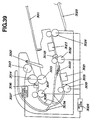
  • Fig. 39 is a typified cross-sectional view showing a schematic structure of the image reading section in the facsimile machine.
  • numeral 3012 is an original document existing-nonexisting detecting sensor for detecting whether or not original documents D are set on the original document mounting tray 3011;
  • numeral 3013 is a pickup roller for feeding the original documents D thus set to the internal of the image reading section 3002;
  • numeral 3014 and 3015 are a separating roller and a reverse roller working in cooperation with each other for separating a plural number of the original documents D and for feeding the separated sheet of the original documents;
  • numeral 3016 is an original document feeding sensor for detecting a front end or rear end of the separated original document D;
  • numeral 3017 is a conveying roller pair for conveying the separated original document D to a U-turn path 3018 which is a U-turn shaped conveying route;
  • numeral 3019 is a conveying roller pair for conveying the original document D after performing U-turn to a front surface reading
  • the above-mentioned conveying route switching flapper 3033 is freely rotatably attached at the branching portion of the reverse path 3034 which branches off from the U-turn path 3018 on an upstream side of the back surface reading section 3023 serving as a reading means provided on a downstream side in the conveying direction.
  • the conveying route switching flapper 3033 is so structured as to move rotationally by the original document conveyed in a forward direction in the U-turn path 3018 to open the path 3018, functioning as a guide for the path 3018 at the branching portion with the reverse path 3034.
  • the conveying route switching flapper 3033 is so constructed as to move rotationally by passage of the rear end of the original document, thereby shutting down the path 3028 to move to a position which leads the original document to the reverse path 3034, functioning as a guide for the reverse path 3034 at the branching portion with the U-turn path 3018 and the reverse path 3034.
  • the above-mentioned reverse path 3034 is so structured, after crossing the U-turn path 3018, as to form a U-turn shaped path upwardly from a portion between the front surface reading section 3021 and the conveying roller pair 3032 toward a portion between the conveying roller pair 3017 and the conveying roller pair 3019, thus to able to lead the original document conveyed in reverse direction onto the original document mounting tray 3011.
  • an original document sandwiching part of the conveying roller pair 3019, an original document sandwiching part of the sheet delivering roller pair 3024, an original document sandwiching part of the conveying roller pair 3032, an original document reading position by the front surface reading section 3021 and an original document reading position by the back surface reading section 3023 are positioned to be approximately in a straight line.
  • the image reading section 3002 is so structured as to be suitably controlled by a controlling circuit (controlling means) although not shown in the figures; for example, those are controlled such as an image processing circuit (image processing means) for processing the image information of the original document D read by the front surface reading section 3021 and the back surface reading section 3023 and a switching circuit (switching means) for switching, as an inputting source of the image information, to the front surface reading section 3021 or to the back surface reading section 3023.
  • a controlling circuit controlling means
  • switching means switching means for switching, as an inputting source of the image information
  • the original document existing-nonexisting detecting sensor 3012 detects the original documents (See, S3002, Fig. 42).
  • the user selects a double-sided reading mode, and then directs to start reading operation (S3003).
  • start reading operation S3003
  • one-sided reading mode the operation is switched to the conventionally known one-sided reading operation (detailed description omitted).
  • the electromagnetic clutch 2027 After receiving the direction for starting reading operation, the electromagnetic clutch 2027 connects the driving for the pickup roller 3013, the separating roller 3014, and the reverse roller 3015 (S3004).
  • the drive motor 3026 rotates in a forward direction (S3005), and then the pickup roller 3013 directly presses the original documents D set on the original document mounting tray 3011 to start picking-up conveyance of the original document D to the inside of the apparatus (S3006).
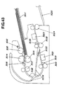
  • the original documents D after picking-up conveyance are to be separated by the separating roller 3014 and the reverse roller 3015, and an uppermost sheet of the original documents is fed in a separating way (See, S3007, Fig. 43).
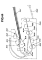
  • the original document D after performing U-turn is conveyed by the conveying roller pair 3019, and the front end of the original document D is detected by the original document edge sensor 3031 (S3011), and then at the place where the original document is conveyed by a predetermined amount from the detected place, the front surface reading section 3021 starts reading the front surface of the original document (See, S3012, Fig. 45).
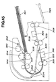
  • the electromagnetic clutch 3027 blocks the driving for the pickup roller 3013, the separating roller 3014, and the reverse roller 3015, and consequently the following original documents is to be stopped without being conveyed (See, S3014, Fig. 46).
  • the front surface reading section 3021 finishes reading operation of the front surface of the original document at a place where the original document is conveyed by a predetermined amount from the detected place (S3016).
  • the original document D is conveyed by the conveying roller pair 3032 to further downstream side, and when the rear end of the original document passes the conveying route switching flapper 3033 (See, S3017, Fig. 47), the drive motor 3026 rotates in a reverse direction (S3018).
  • the original document D is conveyed in a reverse direction by the conveying roller pair 3032 and the sheet delivering roller pair 3024 and led to the reverse path 3034 by the conveying route switching flapper 3033 (See, S3019, Fig. 48).
  • the drive motor 3026 rotates again in a forward direction (See, S3021, Fig. 49).
  • the original document edge sensor 3035 detects the front end of the original document D (S3022), and at a place where the original document is conveyed by a predetermined amount from the detected place, the back surface reading section 3023 starts reading operation of the back surface of the original document (See, S3023, Fig. 50).
  • the original document edge sensor 3035 detects the rear end of the original document D (S3024), and at a place where the original document is conveyed by a predetermined amount from the detected place, the back surface reading section 3023 finishes reading operation of the back surface of the original document (S3025). Then, the original document D is delivered by the sheet delivering roller pair 3024 onto the sheet delivering tray 3025 (See, S3026, Fig. 51).
  • Step S3004 When the original document existing-nonexisting detecting sensor 3012 detects original documents D, operation is returned to Step S3004, as mentioned above, where the electromagnetic clutch 3027 connects the driving for the pickup roller 3013, the separating roller 3014, and the reverse roller 3015, thereby conveying the following original documents; if the sensor 3012 detects no documents, reading operation is completed (S3027).
  • the reverse path 3034 is so structured as to cross the U-turn path 3018 in a manner of extending from a portion between the front surface reading section 3021 and the conveying roller pair 3032 toward a portion between the conveying roller pair 3017 and the conveying roller pair 3019, the original document does not enter into the front surface reading section 3021 even if it is conveyed in a reverse direction.
  • the apparatus is not made larger compared with the apparatus having a general U-turn conveying route.
  • the reverse path 3034 is so constructed to form an upwardly U-turn shaped conveying route after crossing the U-turn path 3018, thereby leading the original document onto the original document mounting tray 3011, a space for installing the apparatus can be reduced as smaller as possible.
  • the respective original document sandwiching part of the conveying roller pair 3019, sheet delivering roller pair 3024, and conveying roller pair 3032 and the respective original document reading positions of the front surface reading section 3021 and the back surface reading section 3023 are positioned approximately in a straight line, and therefore the original document is surely pressed firmly with the original document reading positions of the front surface reading section 3021 and the back surface reading section 3023, and also the rear end of the original document does not flap wildly after passing through the conveying roller pair 3019 and the conveying roller pair 3032, thus to be able to perform good reading operation without image shocks.
  • respective image information can be sequentially sent to single image processing means by switching two reading means (front surface reading section 3021 and back surface reading section 3023), and therefore a plural number of the image processing means are not required, and also simplification of the electric circuit as well as miniaturization of the base board can be achieved, thereby lowering the cost.
  • the apparatus can start reading the image information from the front end of the original document D, so an image reverse means for reversing the image information thus read or an original document reverse means for reversing the original document upside down is not required. Therefore, it is possible to simplify the electric circuit, miniaturize the base board, lower cost for an apparatus, and simplify the structure of the apparatus.
  • a U-turn path is exemplified as an original document conveying route, but the present invention is not limited to this; for example, a straight path can provide the same advantage.
  • a flapper is exemplified as a conveying route switching means, but the invention is not limited to this; for example, a Mylar or the like can be used where the sheet may progress in a forward direction by pushing the Mylar, while progressing in a reverse direction by introduction of the Mylar along it.
  • an image reading section in a facsimile machine is exemplified as an image reading apparatus, but the present invention is not limited to this; the same advantage can be obtained by applying the present invention to, for example, a scanner unit as an image reading apparatus, an image reading apparatus in a copying machine, or an image reading apparatus or the like in a composite apparatus suitably combining a printing function, facsimile function, copying function or the like.
  • respective image information can be sequentially sent to single image processing means by switching two reading means, and therefore a plural number of the image processing means are not required, and also simplification of the electric circuit as well as miniaturization of the base board can be achieved, thus to be capable of lowering the cost.
  • the apparatus can start reading the image information from the front end of the original document D, so an image reverse means for reversing the image information thus read or an original document reverse means for reversing the original document upside down is not required. Therefore, it is possible to simplify the electric circuit, miniaturize the base board, lower cost for an apparatus, and simplify the structure of the apparatus.
  • the branching conveying route is structured from a portion between the first reading means and the second reading means so as to cross the U-turn conveying route, the original document does not enter again into the first reading means even if it is conveyed in a reverse direction, thus to be able to lower the cost for the first reading means as well as lower the height of the apparatus.
  • branching conveying route is so constructed as to form again an upwardly U-turn shaped conveying route after crossing the U-turn conveying route, thereby leading the original document onto the original document mounting tray, a space for installing the apparatus can be reduced as smaller as possible.
  • the original document sandwiching part of the second conveying means, the original document sandwiching part of the third conveying means, the original document sandwiching part of the fourth conveying means, the original document reading position of the first reading means and the original document reading position of the second reading means are positioned approximately in a straight line, and therefore the original document is surely pressed firmly with the original document reading positions, and also the original document does not flap wildly, thus to be able to perform good reading operation without image shocks.
  • Fig. 52 is a structural view at the time the fifth embodiment of the image reading apparatus according to this invention is applied to a facsimile machine;
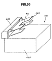
  • Fig. 53 is a perspective view showing the facsimile machine shown in Fig. 52.
  • the facsimile machine shown in Fig. 52 and Fig. 53 is the fifth embodiment of the image forming apparatus according to the present invention.
  • numeral 4101 is a main body of the facsimile machine
  • numeral 4102 is an image reading section utilizing the double-sided image reading apparatus according to the invention, the image reading section arranged in an upper portion of the facsimile machine body 4101
  • numeral 4103 is an image forming section arranged in a lower portion of the machine main body
  • numeral 4111 is an original document tray for setting original documents.
  • numeral 4112 is an original document existing-unexisting sensor for detecting the setting of the original documents
  • numeral 4113 is a pickup roller for sending the original documents thus set to an internal of the apparatus
  • numeral 4114 and 4115 are a separating roller and a reverse roller for separating, in cooperation with each other, the sent original document sheet by sheet
  • numeral 4116 is an original document feeding sensor for detecting a front end and rear end of the separated original document.
  • Numeral 4117 is a conveying roller A for conveying the separated original document to a U-turn path 4118 serving as a U-turn shaped conveying route
  • numeral 4119 is a forwardingly-reversingly rotatable conveying roller B for conveying the original document after performing U-turn to a front surface reading section 4121 composed of a pressing type image sensor.
  • Numeral 4120 is an original document edge sensor for detecting a front end and rear end of the original document in order to determine the timing of starting and finishing of the reading operation of the original document; numeral 4122 is a reverse path serving as a conveying route of the original document during reverse movement; numeral 4123 is a back surface reading section composed of a pressing type image sensor; and numeral 4124 is a forwardingly-reversingly rotatable sheet delivering roller for delivering the original document after read onto a sheet delivering tray 4125.
  • Numeral 4126 is a drive motor for driving the pickup roller 4113, the separating roller 4114, the reverse roller 4115, the conveying roller A4117, the conveying roller B4119, the sheet delivering roller 4124 and the like
  • numeral 4127 is an electromagnetic clutch for temporarily blocking the driving by the drive motor 4126 for the pickup roller 4113, separating roller 4114, reverse roller 4115 and the like.
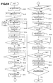
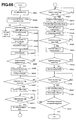
  • Fig. 54 shows a flow chart of the operation of the fifth embodiment of the image forming apparatus according to the invention shown in Fig. 52 and Fig. 53
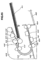
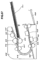
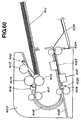
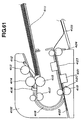
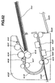
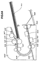
  • Fig. 55 to Fig. 64 show summarized views showing operations of the image forming apparatus shown in Fig. 52 and Fig. 53.
  • original documents are set on the original document tray 4111 (S4101), and the original document existing-nonexisting sensor 4112 detects the original documents (S4102, Fig. 55).
  • a user selects a double-sided reading mode and directs to start reading operation (S4103), and the electromagnetic clutch 4127 connects the driving for the pickup roller 4113, the separating roller 4114, and the reverse roller 4115 (S4104).
  • the drive motor 4126 rotates in a forward direction (S4105) to make the pickup roller 4113 directly pressed with the original documents, thus to send the original documents to the inside of the apparatus (S4106).
  • the original documents are separated by means of the separating roller 4114 and the reverse roller 4115, and an uppermost sheet of the original documents is conveyed in a separate way (S4107, Fig. 56).
  • a conveying speed by the separating roller 4114 is slower than the set original document conveying speed in order to reduce damages of the original documents at the time of separation, and it is also slower because it is subjected to conveying resistance given by the reverse roller 4115.
  • the separated original document is conveyed to the U-turn path 4118 by the conveying roller A4117 having a circumferential speed faster than the predetermined original document conveying speed (S4110).
  • the conveying roller A4117 offsets the delay which is produced by the separating roller 4114 and the reverse roller 4115, and the original document is conveyed at approximately predetermined speed.
  • the conveying speed of the conveying roller A4117 is set beforehand so as to offset the delay by the separating roller 4114 and the reverse roller 4115.
  • the conveying roller B4119 having a circumferential speed of the approximately set original document conveying speed conveys the original document
  • the front surface reading section 4121 starts reading operation of the front surface of the original document at a place where the original document is conveyed by a predetermined amount from the detected place (S4112, Fig. 58).
  • the original document is conveyed at an approximately set original document conveying speed.
  • the original document conveying speed of the sheet delivering roller 4124 is set so as to be slightly faster than the set original document conveying speed, that is, the original document conveying speed of the conveying roller B4119, and the conveying force of the sheet delivering roller 4124 is set so as to be lower than that of the conveying roller B4119.
  • the original document is conveyed, as well in this time, at an approximately set original document conveying speed. That is, provided that a conveying speed of the conveying roller A4117 is V1, a conveying speed of the conveying roller B4119 is V2, and a conveying speed of the sheet delivering roller 4124 is V3, the relation of those above is shown as V1 ⁇ V2 and V2 ⁇ V3.
  • changing each diameter or circumferential speed of the rollers can change the conveying speed.
  • the electromagnetic clutch 4127 blocks the driving for the pickup roller 4113, the separating roller 4114, and the reverse roller 4115, and consequently the following original document is to be stopped without being conveyed (S4114, Fig. 59).
  • the front surface reading section 4121 finishes reading operation of the front surface of the original document at a place where the original document is conveyed by a predetermined amount from the detected place (S4116, Fig. 10).
  • the drive motor 4126 rotates in a reverse direction (S4117), and the original document is conveyed in a reverse direction by the conveying roller B4119 and the sheet delivering roller 4124, and then conveyed to the reverse path 4122 by means of the shape of the intersecting portion of the U-turn path 4118 and the reverse path 4122 (S4118, Fig. 61).
  • the drive motor 4126 again rotates in a forward direction (S4120). The slackness of the original document is eliminated because the original document is conveyed further to the predetermined position after passing through the sheet delivering roller 4124.
  • the back surface reading section 4123 starts reading operation of the back surface of the original document at a place where the original document is conveyed by a predetermined amount from the detected place (S4122, Fig. 63).
  • the back surface reading section 4123 finishes reading operation of the back surface of the original document at a place where the original document is conveyed by a predetermined amount from the detected place (S4124), and consequently the sheet delivering roller 4124 delivers the original document onto the sheet delivering tray 4125 (S4125, Fig. 64).
  • Making the conveying speed of the sheet delivering roller 4124 faster than the set original document conveying speed can prevent the original document from being slack at the first and second reading means.
  • Step S4104 when the original document existing-nonexisting sensor 4112 detects original documents, operation is returned to Step S4104 where the electromagnetic clutch 4127 connects the driving for the pickup roller 4113, the separating roller 4114, and the reverse roller 4115 to convey the following original documents; when no original documents are detected, reading operation is completed (S4126).
  • the fifth embodiment of the image reading apparatus and image forming apparatus can improve the processing ability of the apparatus because the conveying speed of the conveying roller A4117 is set so as to offset the delay caused by the separating roller 4114 and the reverse roller 4115, and can also convey the original document in a position most suitable for reading operation by the front surface reading section 4121 and the back surface reading section 4123 because the tension by slight difference of the conveying speeds between the conveying roller B4119 and the sheet delivering roller 4124 is applied to the original document.
  • a sixth embodiment of an image reading apparatus and an image forming apparatus according to the invention will be hereinafter described with reference to Fig. 65 to Fig. 76.
  • the same members as those above-mentioned members in Fig. 54 to Fig. 64 are referred as the same numerals.
  • Fig. 65 is a structural view at the time the sixth embodiment of the image reading apparatus according to this invention is applied to a facsimile machine.
  • the facsimile machine shown in Fig. 65 is also the fifth embodiment of the image forming apparatus according to the present invention.
  • numeral 4111 is an original document tray for setting original documents
  • numeral 4112 is an original document existing-nonexisting sensor for detecting the setting of the original document documents
  • numeral 4113 is a pickup roller for sending the original documents thus set to an internal of the apparatus
  • numeral 4114 and 4115 are a separating roller and a reverse roller for separating, in cooperation with each other, the sent original document sheet by sheet
  • numeral 4116 is an original document feeding sensor for detecting a front end and rear end of the separated original document.
  • Numeral 4117 is a conveying roller A for conveying the separated original document to a U-turn path 4118 serving as a U-turn shaped conveying route;
  • numeral 4119 is a conveying roller B for conveying the original document after performing U-turn to a front surface reading section 4121 composed of a pressing type image sensor;
  • numeral 4201 is an original document edge sensor A for detecting a front end and rear end of the original document in order to determine the timing of the starting and finishing the reading operation of the front surface of the original document by the front surface reading section 4121.
  • Numeral 4202 is a forwardingly-reversingly rotatable conveying roller C for conveying the original document after its front surface is read to further downstream side
  • numeral 4203 is a conveying route switching flapper which is open when an end of the original document enters from a forward direction (Arrow P direction) while it is shut down when an end of the original document enters from a reverse direction (Arrow Q direction) to lead the original document to a reverse path 4204.
  • Numeral 4205 is an original document edge sensor B for detecting a front end and rear end of the original document in order to determine the timing of starting and finishing of the reading operation of the back surface of the original document by a back surface reading section 4123 composed of a pressing type image sensor, and numeral 4124 is a forwardigly-reversingly rotatable sheet delivering roller for delivering the original document after reading operation onto a sheet delivering tray 4125.
  • Numeral 4126 is a drive motor for driving the pickup roller 4113, the separating roller 4114, the reverse roller 4115, the conveying roller A4117, the conveying roller B4119, the conveying roller C4202, and the sheet delivering roller 4124
  • numeral 4127 is an electromagnetic clutch for temporarily blocking the driving by the drive motor 4126 for the pickup roller 4113, separating roller 4114, and reverse roller 4115.
  • Fig. 66 shows a flow chart of the operation of the sixth embodiment of the image forming apparatus according to the invention
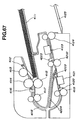
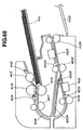
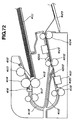
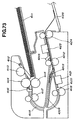
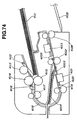
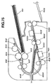
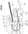
  • Fig. 67 to Fig. 76 show summarized views showing operations of the sixth embodiment of the image forming apparatus.
  • a user sets original documents on the original document tray 4111 (S4201), and then the original document existing-nonexisting sensor 4112 detects the original documents (S4202, Fig. 67).
  • the user selects a double-sided reading mode and directs to start reading operation (S4203), and the electromagnetic clutch 4127 connects the driving for the pickup roller 4113, the separating roller 4114, and the reverse roller 4115 (S4204).
  • the drive motor 4126 rotates in a forward direction (S4205) to make the pickup roller 4113 directly pressed with the original documents, thus to send the original documents to the inside of the apparatus (S4206).
  • the original documents are separated by means of the separating roller 4114 and the reverse roller 4115, and an uppermost sheet of the original documents is conveyed in a separate way (S4207, Fig. 68).
  • a conveying speed by the separating roller 4114 is slower than the set original document conveying speed in order to reduce damages of the original documents at the time of separation, and it is also slower because it is subjected to conveying resistance given by the reverse roller 4115.
  • the separated original document is conveyed to the U-turn path 4118 by the conveying roller A4117 having a conveying speed faster than the predetermined original document conveying speed (S4210).
  • the conveying roller A4117 offsets the delay which is produced by the separating roller 4114 and the reverse roller 4115, and the original document is conveyed at approximately predetermined speed.
  • the circumferential speed of the conveying roller A4117 is set beforehand so as to offset the delay by the separating roller 4114 and the reverse roller 4115.
  • the conveying roller B4119 having a circumferential speed of an approximately set original document conveying speed conveys the original document
  • the front surface reading section 4121 starts reading operation of the front surface of the original document at a place where the original document is conveyed by a predetermined amount from the detected place (S4212, Fig. 70).
  • a circumferential speed of the conveying roller C4202 is set as an approximately set original document conveying speed.
  • the original document is conveyed at an approximately set original document conveying speed.
  • the original document conveying speed of the sheet delivering roller 4124 is set so as to be slightly faster than the set original document conveying speed, and the conveying force of the roller is set so as to be lower than that of the conveying roller C4202.
  • the sheet delivering roller 4124 staffs conveying the original document, a slight difference in the conveying speeds between the conveying roller C4202 and the sheet delivering roller 4124 applies tension to the original document.
  • the original document is conveyed as well in this time at an approximately set original document conveying speed because the difference in the conveying speeds between the conveying roller C4202 and the sheet delivering roller 4124 is slight and because the conveying force is set so as to be lower than that of the conveying roller C4202.
  • the electromagnetic clutch 4127 blocks the driving for the pickup roller 4113, the separating roller 4114, and the reverse roller 4115, and consequently the following original document is to be stopped without being conveyed (S4214, Fig. 71).
  • the front surface reading section 4121 finishes reading operation of the front surface of the original document at a place where the original document is conveyed by a predetermined amount from the detected place (S4216).
  • the original document is conveyed to further downstream side by the conveying roller C4202, and when the rear end of the original document passes the conveying route switching flapper 4203 (S4217, Fig. 72), the drive motor 4126 rotates in a reverse direction (S4218).
  • the original document is conveyed in a reverse direction by the conveying roller C4202 and the sheet delivering roller 4124, and then conveyed to the reverse path 4204 by the conveying route switching flapper 4203 (S4219, Fig. 73).
  • the original document becomes slack little by little between the conveying roller C4202 and the sheet delivering roller 4124 by the difference in those conveying speeds, there is no influence on images because the front surface reading section 4121 and the back surface reading section 4123 do not conduct the reading operation.
  • the drive motor 4126 again rotates in a forward direction (S4221, Fig. 74).
  • the slackness of the original document is eliminated because the original document is conveyed further to the predetermined position after passing through the sheet delivering roller 4124.
  • the back surface reading section 4123 starts reading operation of the back surface of the original document at a place where the original document is conveyed by a predetermined amount from the detected place (S4223, Fig. 75).
  • the circumferential speed of the sheet delivering roller 4124 is set so as to be slightly faster than the set original document conveying speed, and the conveying force of the roller 4124 is set so as to be lower than that of the conveying roller C4202.
  • the back surface reading section 4123 finishes reading operation of the back surface of the original document at a place where the original document is conveyed by a predetermined amount from the detected place (S4225), and consequently the sheet delivering roller 4124 delivers the original document onto the sheet delivering tray 4125 (S4226, Fig. 76).
  • Making the conveying speed of the sheet delivering roller 4124 faster than the set original document conveying speed can prevent the original document from being slack at the first and second reading means.
  • Step S4204 When the original document existing-nonexisting sensor 4112 detects original documents, operation is returned to Step S4204 where the electromagnetic clutch 4127 connects the driving for the pickup roller 4113, the separating roller 4114, and the reverse roller 4115 to convey the following original documents; when no original documents are detected, reading operation is completed (S4227). That is, provided that a conveying speed of the conveying roller A4117 is V1, a conveying speed of the conveying roller B4119 is V2, a conveying speed of the sheet delivering roller 4124 is V3, and a conveying speed of the conveying roller C4202 is V4, the relation of those above is shown as V1 ⁇ V2, V2 ⁇ V3, V4 ⁇ V3, and V2 ⁇ V4.
  • the sixth embodiment of the image reading apparatus and image forming apparatus can improve processing ability of the apparatus because the conveying speed of the conveying roller A4117 is set so as to offset the delay caused by the separating roller 4114 and the reverse roller 4115, and can also convey the original document in a position most suitable for reading operation by the front surface reading section 4121 and the back surface reading section 4123 because the tension by slight difference of the conveying speeds between the conveying roller C4202 and the sheet delivering roller 4124 is applied to the original document, and furthermore, the embodiment of the apparatus can achieve a double-sided reading operation while further promoting the saving of the space.
  • a conveying speed V1 of the first conveying means arranged downstream of the original document feeding means, a conveying speed V2 of the second conveying means arranged upstream of the first image reading means, and a conveying speed V3 of the third conveying means arranged downstream of the second image reading means satisfy the condition V1 ⁇ V2, V2 ⁇ V3, such an image reading apparatus and an image forming apparatus can be provided where the first conveying means can eliminate the delay of the conveying speed caused by the automatic original document feeding means; the original document can be conveyed at a set original document conveying speed; and then, by positioning the first conveying means adjacent to the automatic original document feeding means, the delay of the conveying speed by the automatic original document feeding means can immediately be eliminated, thereby making it possible to improve the processing ability.
  • the first conveying means eliminates the delay of the conveying speed by the automatic original document feeding means
  • an image reading apparatus and an image forming apparatus can be provided where the original document can be conveyed, during the reading operation at the first image reading means, variably at a set original document conveying speed due to the second conveying means having a circumferential speed of the set original document conveying speed, and where the original document can be conveyed, during the reading operation at the second image reading means, variably at a set original document conveying speed due to the conveyance by the second conveying means having a circumferential speed of the original document conveying speed.
  • tension is applied to the original document by a slight difference in the circumferential speeds between the second conveying means and the third conveying means, and consequently the original document can be conveyed in a position most suitable for reading operations by the first and the second image reading means, thus to provide an image reading apparatus and an image forming apparatus capable of constantly obtaining good images on the both of the front and the back sides without image stretching or image shocks.
  • a conveying speed V1 of the first conveying means arranged downstream of the original document feeding means, a conveying speed V2 of the second conveying means arranged upstream of the first image reading means, a conveying speed V3 of the third conveying means arranged downstream of the second image reading means, and a conveying speed V4 of the fourth conveying means arranged between the first image reading means and the second image reading means satisfy the condition V1 ⁇ V2, V4 ⁇ V3, V2 ⁇ V4, such an image reading apparatus and an image forming apparatus can be provided where the first conveying means can eliminate the delay of the conveying speed caused by the automatic original document feeding means; the original document can be conveyed at a set original document conveying speed; and then, by positioning the first conveying means adjacent to the automatic original document feeding means, the delay of the conveying speed by the automatic original document feeding means can immediately be eliminated, making it possible to maximize the processing ability.
  • tension is applied to the original document by a slight difference in the circumferential speeds between the third conveying means and the fourth conveying means, and consequently the original document can be conveyed in a position most suitable for reading operations by the first and the second image reading means, thus to provide an image reading apparatus and an image forming apparatus capable of constantly obtaining good images on the both of the front and the back sides without image stretching or image shocks.
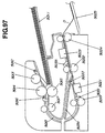
  • An image reading apparatus will hereinafter be described with reference to Fig. 77 to Fig. 89.
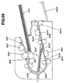
  • a structure of an image reading apparatus in a facsimile machine is explained by way of example.
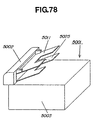
  • Fig. 78 is a perspective view showing an exterior appearance of a facsimile machine.
  • numeral 5001 refers to a main body of the machine
  • numeral 5002 refers to an image reading section according to the invention arranged in an upper portion of the machine main body 5001
  • numeral 5003 refers to an image forming section arranged in a lower portion of the machine main body 5001
  • numeral 5011 refers to an original document mounting tray for setting original documents D
  • numeral 5025 refers to a sheet delivering tray.
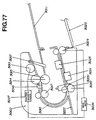
  • Fig. 77 is a typified cross-sectional view showing a schematic structure of the image reading section in the facsimile machine.
  • numeral 5012 is an original document existing-nonexisting detecting sensor for detecting original documents D which are set on the original document mounting tray 5011;
  • numeral 5013 is a pickup roller for feeding the original documents D thus set into the internal of the image reading section 5002;
  • numeral 5014 and 5015 are a separating roller and a reverse roller working in cooperation with each other for separating the original documents D sheet by sheet and for feeding a separated sheet of the original documents;
  • numeral 5016 is an original document feeding sensor for detecting a front end or rear end of the separated original document D;
  • numeral 5017 is a first conveying roller pair for conveying the separated original document D to a U-turn path 5018 which is a U-turn shaped conveying route;
  • numeral 5019 is a second conveying roller pair for conveying the original document D after performing U-turn to a front surface reading
  • V5 indicates an original document conveying speed set for reading operation
  • V6 indicates a reverse conveying speed faster than the set original document conveying speed V5
  • t2 is a time starting from a moment where an end of an original document arrives at the original document edge sensor 5020 when conveyed at a reverse conveying speed V6 until a moment where the original document edge sensor 5020 starts detecting the end of the original document
  • l 1 is a distance from the second conveying roller pair 5019 to the original document edge sensor 5020
  • l 2 is a distance required for the original document at a reverse conveying speed V6 to be stopped.
  • the image reading section 5002 is so structured as to be suitably controlled by the controlling circuit (controlling means) although not shown in the figures; for example, those are controlled such as an image processing circuit (image processing means) for processing the image information of the original document D read by the front surface reading section 5021 and the back surface reading section 5023 as well as a switching circuit (switching means) for switching, as an inputting source of the image information, to the front surface reading section 5021 or to the back surface reading section 5023.
  • the controlling circuit controlling means
  • the original document existing-nonexisting detecting sensor 5012 detects the original documents (See, S5102, Fig. 80).
  • the user selects a double-sided reading mode, and then directs to start reading operation (S5103).
  • start reading operation S5103
  • one-sided reading mode the operation is switched to the conventionally known one-sided reading operation (detailed description omitted).
  • the electromagnetic clutch 5027 After receiving the direction for starting reading operation, the electromagnetic clutch 5027 connects the driving for the pickup roller 5013, the separating roller 5014, and the reverse roller 5015 (S5104).
  • the drive motor 5026 rotates in a forward direction (S5105), and then the pickup roller 5013 directly presses the original documents D set on the original document mounting tray 5011 to start picking-up conveyance of the original document D into the inside of the apparatus (S5106).
  • the original documents D after picking-up conveyance are to be separated by the separating roller 5014 and the reverse roller 5015, and an uppermost sheet of the original documents is fed in a separating way (See, S5107, Fig. 81).
  • a conveying speed by the separating roller 5014 is slower than the set original document conveying speed V5 in order to reduce damages of the original documents at the time of separation, and it is also slower because it is subjected to conveying resistance given by the reverse roller 5015.
  • the separated original document D is conveyed to the U-turn path 5018 by the first conveying roller pair 5017 having a circumferential speed faster than the set original document conveying speed V5 (S5110).
  • the first conveying roller pair 5017 offsets the delay which are produced by the separating roller 5014 and the reverse roller 5015, and the original document is conveyed at approximately set original document conveying speed V5.
  • the circumferential speed of the first conveying roller pair 5017 is set beforehand so as to offset the delay by the separating roller 5014 and the reverse roller 5015.
  • the second conveying roller pair 5019 having a circumferential speed of the approximately set original document conveying speed V5 conveys the original document D
  • the front surface reading section 5021 starts reading operation of the front surface of the original document at a place where the original document is conveyed by a predetermined amount from the detected place (See, S5112, Fig. 83).
  • the original document is conveyed at an approximately set original document conveying speed V5.
  • the circumferential speed of the sheet delivering roller pair 5024 is set so as to be slightly faster than the set original document conveying speed V5, and the conveying force of the roller pair is set so as to be lower than that of the second conveying roller pair 5019.
  • the electromagnetic clutch 5027 blocks the driving for the pickup roller 5013, the separating roller 5014, and the reverse roller 5015, and consequently the following original document is to be stopped without being conveyed (See, S5114, Fig. 84).
  • the front surface reading section 5021 finishes reading operation of the front surface of the original document at a place where the original document is conveyed by a predetermined amount from the detected place (See, S5116, Fig. 85).
  • the drive motor 5026 rotates in a reverse direction (S5117), and the original document is conveyed by the second conveying roller pair 5019 and the sheet delivering roller 5024 in a reverse direction at a reverse conveying speed V6 which is faster than the approximately set original document conveying speed V5, and then conveyed to the reverse path 5022 by means of the shape of the intersecting portion of the U-turn path 5018 and the reverse path 5022 (See, S5118, Fig. 86).
  • the distance l 1 between the original document edge sensor 5020 and the second conveying roller pair 5019 is set so as to be longer than a combined distance of V6 ⁇ t2, which is a conveyance distance until that the original document edge sensor 5020 detects the end of the original document, with l 2, which is a distance required for the original document at a reverse conveying speed V6 to be stopped ( l 1 > V6 ⁇ t2 + l 2) , it will not happen that the original document goes through out of the second conveying roller pair 5019, resulting in that re-conveyance cannot be conducted.
  • the back surface reading section 5023 starts reading operation of the back surface of the original document at a place where the original document is conveyed by a predetermined amount from the detected place (See, S5122, Fig. 88).
  • the back surface reading section 5023 finishes reading operation of the back surface of the original document at a place where the original document is conveyed by a predetermined amount from the detected place (S5124), and consequently the original document D is delivered by the sheet delivering roller pair 5024 onto the sheet delivering tray 5025 (See, S5125, Fig. 89).
  • Making the circumferential speed of the sheet delivering roller pair 5024 slightly faster than the set original document conveying speed V5 can prevent the original document from being slack at the first reading section 5021 and the back surface reading section 5023.
  • Step S5104 the electromagnetic clutch 5027 connects the driving for the pickup roller 5013, the separating roller 5014, and the reverse roller 5015 to convey the following original documents; when no original documents are detected, reading operation is completed (S5126).
  • the reverse conveying speed V6 as a conveying speed at the time of conveying the original document in a reverse direction is set so as to be faster than the approximately set original document conveying speed V5 as a conveying speed at the time of reading images, and therefore, the operation time for double-sided reading is reduced, thus to be capable of increasing efficiency.
  • the distance l 1 between the second conveying roller pair 5019 and the original document edge sensor 5020 (See, Fig. 80) is set so as to be longer than the reverse conveying distance after the detection of the original document edge sensor, or V6 ⁇ t2 + l 2 , this can prevent the situation that the original document D goes through out of the nip part of the second conveying roller pair 5019, resulting in that the second conveying roller pair 5019 cannot convey again the original document D.
  • FIGS from Fig. 90 to Fig. 101 An image reading apparatus according to an eighth embodiment will hereinafter be described with reference to FIGS from Fig. 90 to Fig. 101.
  • a structure of an image reading apparatus in a facsimile machine is explained by way of example.
  • Fig. 90 is a typified cross-sectional view showing a schematic structure of the image reading section in the facsimile machine.
  • numeral 5011 is an original document mounting tray for setting original documents D
  • numeral 5012 is an original document existing-nonexisting detecting sensor for detecting the set original documents D on the original document mounting tray 5011
  • numeral 2013 is a pickup roller for feeding the original documents D thus set to the internal of the image reading section 5002
  • numeral 14 and 15 are a separating roller and a reverse roller working in cooperation with each other for separating the sent original documents D sheet by sheet and for feeding the separated sheet of the original documents
  • numeral 5016 is an original document feeding sensor for detecting a front end or rear end of the separated original document D
  • numeral 5017 is a first conveying roller pair for conveying the separated original document D to a U-turn path 5018 which is a U-turn shaped conveying route
  • numeral 5019 is a second conveying roller pair for conveying the original document D after performing U-
  • V5 indicates an original document conveying speed set for reading operation
  • V6 indicates a reverse conveying speed faster than the set original document conveying speed V5
  • t2 is a time starting from a moment where an end of an original document arrives at the second original document edge sensor 5035 when conveyed at a reverse conveying speed V6 until a moment where the second original document edge sensor 5035 starts detecting the end of the original document
  • l 1 is a distance from the third conveying roller pair 5032 to the second original document edge sensor 5035
  • l 2 is a distance required for the original document at a reverse conveying speed V6 to be stopped.
  • the image reading section 5002 is so structured as to be suitably controlled by the controlling circuit (controlling means) although not shown in the figures; for example, those are controlled such as an image processing circuit (image processing means) for processing the image information of the original document D read by the front surface reading section 5021 and the back surface reading section 5023 as well as a switching circuit (switching means) for switching, as an inputting source of the image information, to the front surface reading section 5021 or to the back surface reading section 5023.
  • the controlling circuit controlling means
  • the original document existing-nonexisting detecting sensor 5012 detects the original documents (See, S5202, Fig. 92).
  • the user selects a double-sided reading mode, and then directs to start reading operation (S5203).
  • start reading operation S5203
  • one-sided reading mode the operation is switched to the conventionally known one-sided reading operation (detailed description omitted).
  • the electromagnetic clutch 5027 After receiving the direction for starting reading operation, the electromagnetic clutch 5027 connects the driving for the pickup roller 5013, the separating roller 5014, and the reverse roller 5015 (S5204).
  • the drive motor 5026 rotates in a forward direction (S5205), and then the pickup roller 5013 directly presses the original documents D set on the original document mounting tray 5011 to start picking-up conveyance of the original document D into the inside of the apparatus (S5206).
  • the original documents D after picking-up conveyance are to be separated by the separating roller 5014 and the reverse roller 5015, and an uppermost sheet of the original documents is fed in a separating way (See, S5207, Fig. 93).
  • a conveying speed by the separating roller 5014 is slower than the set original document conveying speed V5 in order to reduce damages of the original documents at the time of separation, and it is also slower because it is subjected to conveying resistance given by the reverse roller 5015.
  • the separated original document D is conveyed to the U-turn path 5018 by the first conveying roller pair 5017 having a circumferential speed faster than the set original document conveying speed V5 (S5210).
  • the first conveying roller pair 5017 offsets the delay which are produced by the separating roller 5014 and the reverse roller 5015, and the original document is conveyed at approximately set original document conveying speed V5.
  • the circumferential speed of the first conveying roller pair 5017 is set beforehand so as to offset the delay by the separating roller 5014 and the reverse roller 5015.
  • the circumferential speed of the sheet delivering roller pair 5024 is set so as to be slightly faster than the set original document conveying speed V5, and its conveying force is set so as to be lower than that of the third conveying roller pair 5032.
  • the original document is conveyed, as well in this time, at an approximately set original document conveying speed V5 because the difference in the circumferential speeds between the third conveying roller pair 5032 and the sheet delivering roller pair 5024 is slight and also that a conveying force of the sheet delivering roller pair 5024 is set as to be lower than that of the third conveying roller pair 5032.
  • the electromagnetic clutch 5027 blocks the driving for the pickup roller 5013, the separating roller 5014, and the reverse roller 5015, and consequently the following original document is to be stopped without being conveyed (See, S5214, Fig. 96).
  • the front surface reading section 5021 finishes reading operation of the front surface of the original document at a place where the original document is conveyed by a predetermined amount from the detected place (S5216).
  • the original document D is conveyed by the third conveying roller pair 5032 to the further downstream side, and when the rear end of the original document passes the conveying route switching flapper 5033 (See, S5217, Fig. 97), the drive motor 2026 rotates in a reverse direction (S5218).
  • the original document D is conveyed in a reverse direction by the third conveying roller pair 5032 and the sheet delivering roller pair 5024 and then led to the reverse path 5034 by the conveying route switching flapper 5033 (See, S5219, Fig. 98).
  • the original document is conveyed at a reverse conveying speed V6 which is faster than the approximately set original document conveying speed V5 (V5 ⁇ V6), the processing speed in double-sided reading operation becomes fast, thereby increasing operating efficiency.
  • the distance l 1 between the second original document edge sensor 5035 and the third conveying roller pair 5032 is set so as to be longer than a combined distance of V6 ⁇ t2, which is a conveyance distance until that the second original document edge sensor 5035 detects the end of the original document, with l 2, which is a distance required for the original document at a reverse conveying speed V6 to be stopped ( l 1 > V6 ⁇ t2 + l 2) , it will not happen that the original document goes through out of the third conveying roller pair 5032, resulting in that re-conveyance cannot be conducted.
  • the back surface reading section 5023 finishes reading operation of the back surface of the original document at a place where the original document is conveyed by a predetermined amount from the detected place (See, S5223, Fig. 100).
  • the circumferential speed of the sheet delivering roller pair 5024 is set so as to be slight faster than the set original document conveying speed V5, and the conveying force of the sheet delivering roller pair 5024 is set so as to be lower than that of the third conveying roller pair 5032.
  • the back surface reading section 5023 finishes reading operation of the back surface of the original document at a place where the original document is conveyed by a predetermined amount from the detected place (S5225), and consequently the original document D is delivered by the sheet delivering roller pair 5024 onto the sheet delivering tray 5025 (See, S5226, Fig. 101).
  • Making the circumferential speed of the sheet delivering roller pair 5024 slightly faster than the set original document conveying speed V5 can prevent the original document from being slack at the first reading section 5021 and the back surface reading section 5023.
  • Step S5204 operation is returned to Step S5204 where, as mentioned above, the electromagnetic clutch 5027 connects the driving for the pickup roller 5013, the separating roller 5014, and the reverse roller 5015 to convey the following original documents; when no original documents are detected, reading operation is completed (S5227).
  • the reverse conveying speed V6 as a conveying speed at the time of conveying the original document in a reverse direction is set so as to be faster than the approximately set original document conveying speed V5 as a conveying speed at the time of reading images, and therefore, the operation time for double-sided reading is reduced, thus to be capable of increasing efficiency.
  • the distance l 1 between the third conveying roller pair 5032 and the second original document edge sensor 5035 (See, Fig. 90) is set so as to be longer than the reverse conveying distance after the detection of the second original document edge sensor, or V6 ⁇ t2 + l 2 , this can prevent the situation that the original document D goes through out of the nip part of the third conveying roller pair 5032, resulting in that the third conveying roller pair 5032 cannot convey again the original document D.
  • a U-turn path is exemplified as an original document conveying route, but the present invention is not limited to this; for example, a straight path can provide the same advantage.
  • a flapper is exemplified as a conveying route switching means, but the invention is not limited to this; for example, a Mylar or the like can be used where the sheet may progress in a forward direction by pushing the Mylar, while progressing in a reverse direction by introduction of the Mylar along it.
  • an image reading section in a facsimile machine is exemplified as an image reading apparatus, but the present invention is not limited to this; the same advantage can be obtained by applying the present invention to, for example, a scanner unit as an image reading apparatus, an image reading apparatus in a copying machine, or an image reading apparatus or the like in a composite apparatus suitably combining a printing function, facsimile function, copying function or the like.
  • the conveying speed V6 at the time of conveying the original document in a reverse direction is set so as to be faster than the approximately set original document conveying speed V5 at the time of reading images, and therefore, the operation time for reading the double sides of the original document is reduced, thus to be capable of increasing efficiency.
  • the distance l 1 between the original document detecting means provided on an upstream side of the reading means and the original document conveying roller pair constituting an original document conveying means provided on an upstream side of the original document detecting means is set so as to be longer than the reverse conveying distance from a point where the end of the original document arrives at the original document detecting means to a point where the original document is stopped, or V6 ⁇ t2 + l 2 , this can prevent the situation that the original document goes through out of the original document conveying roller pair, resulting in that re-conveyance cannot be conducted.
  • Present invention relates to an image reading apparatus comprising an original document conveying route, original document conveying means for conveying original documents along the original document conveying route, first reading means for reading an image on one side of the original document; and second reading means for reading an image on the other side of the original document.
  • the first reading means reads an image on one side of the original document while the original document is conveyed in a forward direction by the original document conveying means, and then after the original document is conveyed in a reverse direction, the second reading means reads the other side of the original document while the original document is again conveyed in the forward direction.

Landscapes

  • Engineering & Computer Science (AREA)
  • Multimedia (AREA)
  • Signal Processing (AREA)
  • Facsimile Scanning Arrangements (AREA)
  • Facsimiles In General (AREA)
  • Separation, Sorting, Adjustment, Or Bending Of Sheets To Be Conveyed (AREA)

Abstract

Present invention relates to an image reading apparatus comprising an original document conveying route, original document conveying means for conveying original documents along the original document conveying route, first reading means for reading an image on one side of the original document; and second reading means for reading an image on the other side of the original document. The first reading means reads an image on one side of the original document while the original document is conveyed in a forward direction by the original document conveying means, and then after the original document is conveyed in a reverse direction, the second reading means reads the other side of the original document while the original document is again conveyed in the forward direction.

Description

BACKGROUND OF THE INVENTION 1. Filed of the Invention
The present invention relates to a double-sided image reading apparatus and to an image forming apparatus, such as an image copying apparatus, a facsimile machine, or a composite apparatus combining the above, utilizing the double-sided image reading apparatus.
2. Related Background Art
Conventionally, an apparatus for reading images recorded on both sides of an original document has been proposed, and in Japanese Unexamined Patent Publication Showa No. 60-126964 (first prior art), for example, a structure with two image reading means opposing each other for reading simultaneously double sides of an original document by one-time feeding of the original document is suggested.
Also in Japanese Unexamined Patent Heisei No. 1-126870 (second prior art), a structure having two image reading means opposing each other which sandwich an original document pressing roller for reading respectively each side of an original document by switching back the original document is suggested.
In the above-described first prior art, however, the two image reading means require two image processing means, thereby increasing the production cost. In addition, when an apparatus for one-sided reading as a standard configuration which optionally has a double-sided reading function is to be developed, even the standard configuration having a one-sided reading function requires two image processing means beforehand, resulting in that cost advantage provided by an apparatus having only a one-sided reading function becomes less.
Also, in the above-described second prior art, an original document returned by switching back is to be read from the rear end of the sheet, which causes the image information to be sent upside down page by page when, for example, the information is sent as FAX images. In order to avoid this situation, a means for reversing the up or down side of an image or a conveying means for reversing the up or down side of an image is required, thus making the apparatus structure complicated.
Furthermore, in the conventional original document conveying route of the image reading apparatus, especially an original document conveying route having a U-turn section for sequentially feeding by means of a plural of original document conveying means, when a part of the original document conveying means conveys original documents at a slow speed, the speed as a whole for processing the original documents becomes slow; or when a preceding original document conveying means is fast while a following original document conveying means is slow, the original document conveying means cannot be fitted in the original document conveying route, causing such a problem that the image reading means cannot read images precisely.
SUMMARY OF THE INVENTION
Therefore, it is an object of the present invention to provide an image reading apparatus and an image forming apparatus which are excellent without defects, and more specifically to achieve miniaturization and cost lowering of an image reading apparatus and an image forming apparatus mounting the image reading apparatus.
Also it is an object of the present invention to provide an image reading apparatus and an image forming apparatus capable of reading good images while improving an operating efficiency of the reading process of the original documents by differentiating the conveying speeds between the original document conveying means.
To accomplish the above objects, a representative structure of a double-sided image reading apparatus according to the invention is to structure an original document conveying route, an original document conveying means for conveying an original document along the original document conveying route, a first reading means for reading an image on one side of the original document, and a second reading means for reading an image on the other side of the original document, where an image on one side of an original document is read at the first reading means while the original document is forwardly conveyed by the original document conveying means and then after convey in a reverse direction, the other side of the original document is read at the second reading means while conveyed forwardly again.
According to the above-mentioned image reading apparatus where the image information on the both sides of the original document can be read one by one as well as be read always in the same direction with respect to the up side and down side of the original document, which allows to feed the original document to the single image processing means, there is no need for providing a plural of the image proceeding means, and therefore it is possible to simplify the circuit and miniaturize the base board, thereby achieving cost reduction.
As another structure of the invention, the image reading apparatus of the same as the mentioned above can form a branching conveying route branching off from the original document conveying route at an upstream side, in the conveying direction, of at least one of the image reading means, the branching conveying route capable of guiding the original document conveyed by the original document conveying means.
Because the above-mentioned image reading apparatus has, in addition to the original document conveying route, another branching conveying route for making the original document conveyed in the reverse direction temporarily escape, the original document can escape smoothly even if the original document conveying route has a U-turn shape.
As another structure of the invention, the image reading apparatus might include an original document conveying route having at least a partial curvature section to have a U-turn shaped portion and a reverse path branching off from a midway point on the original document conveying route, the reverse path having at least a partial curvature section to have a U-turn shaped portion.
According to the above-mentioned image reading apparatus, when conveyed in a reverse direction for escape, the original document is returned on an original document mounting tray serving as an original document feeding means, thereby making an apparatus installation space smaller.
As another structure of the invention, an image reading apparatus includes an original document feeding means for feeding stacked original documents, an original document conveying route for conveying the original documents fed from the original document feeding means, at least one image forming means placed in a midway point on the original document conveying route, and a plurality of original document conveying means for conveying the original documents in the original document conveying route, each of the original document conveying means having a document conveying speed different from that of at least one side of adjacent original document conveying means.
In the above-mentioned image reading apparatus, an original document processing efficiency can be improved as a whole in the original document conveying route and also a degree of tension and a degree of flexion of the original documents can be controlled between the plural original document conveying means, and therefore the image reading means can read good images.
BRIEF DESCRIPTION OF THE DRAWINGS
The above and other objects and features of the invention are apparent to those skilled in the art from the following referred embodiments thereof when considered in conjunction with the accompanied drawings, in which:
  • Fig. 1 is a cross-sectional view showing an image reading apparatus of a first embodiment.
  • Fig. 2 is a perspective view showing an exterior appearance of a facsimile machine mounting the image reading apparatus.
  • Fig. 3 is a flow chart showing an operation of the image reading apparatus.
  • Fig. 4 to Fig. 13 are illustrations showing operations of the image reading apparatus.
  • Fig. 14 is a cross-sectional view showing an image reading apparatus of a second embodiment.
  • Fig. 15 is a flow chart showing an operation of the image reading apparatus.
  • Fig. 16 to Fig. 25 are illustrations showing operations of the image reading apparatus.
  • Fig. 26 is a cross-sectional view showing an image reading apparatus of a third embodiment.
  • Fig. 27 is a perspective view showing an exterior appearance of a facsimile machine mounting the image reading apparatus.
  • Fig. 28 is a flow chart showing an operation of the image reading apparatus.
  • Fig. 29 to Fig. 38 are illustrations showing operations of the image reading apparatus.
  • Fig. 39 is a cross-sectional view showing an image reading apparatus of a fourth embodiment.
  • Fig. 40 is a perspective view showing an exterior appearance of a facsimile machine mounting the image reading apparatus.
  • Fig. 41 is a flow chart showing an operation of the image reading apparatus.
  • Fig. 42 to Fig. 51 are illustrations showing operations of the image reading apparatus.
  • Fig. 52 is a cross-sectional view showing an image reading apparatus of a fifth embodiment.
  • Fig. 53 is a perspective view showing an exterior appearance of a facsimile machine mounting the image reading apparatus.
  • Fig. 54 is a flow chart showing an operation of the image reading apparatus.
  • Fig. 55 to Fig. 64 are illustrations showing operations of the image reading apparatus.
  • Fig. 65 is a cross-sectional view showing an image reading apparatus of a sixth embodiment.
  • Fig. 66 is a flow chart showing an operation of the image reading apparatus.
  • Fig. 67 to Fig. 76 are illustrations showing operations of the image reading apparatus.
  • Fig. 77 is a cross-sectional view showing an image reading apparatus of a seventh embodiment.
  • Fig. 78 is a perspective view showing an exterior appearance of a facsimile machine mounting the image reading apparatus.
  • Fig. 79 is a flow chart showing an operation of the image reading apparatus.
  • Fig. 80 to Fig. 89 are illustrations showing operations of the image reading apparatus.
  • Fig. 90 is a cross-sectional view showing an image reading apparatus of an eighth embodiment.
  • Fig. 91 is a flow chart showing an operation of the image reading apparatus.
  • Fig. 92 to Fig. 101 are illustrations showing operations of the image reading apparatus.
  • DESCRIPTION OF THE PREFERRED EMBODIMENTS [First embodiment]
    A first embodiment of a double-sided image reading apparatus according to the invention will hereinafter be described with reference to the drawings. Fig. 1 is a cross-sectional view showing a double-sided image reading apparatus according to the invention. Fig. 2 is a perspective view showing an exterior appearance of the double-sided image reading apparatus. Fig. 3 is a flow chart showing an operation of the double-sided image reading apparatus. Fig. 4 to Fig. 13 are illustrations showing operations of the double-sided image reading apparatus. In the present embodiment, a facsimile machine used as the double-sided image reading apparatus is described.
    A main body 1001 of the facsimile machine shown in Fig. 2 forms, on its upper portion, an image reading section 1002 utilizing the double-sided image reading apparatus of the invention and, on its lower portion, an image forming section 1003. The image reading section 1002 has an original document tray 1004 for stacking original documents to be read and a delivering tray 1005 for discharging and stacking the original documents where reading operation is completed.
    Inside the image reading section 1002 as shown in Fig. 1, a conveying route 1006 is provided so as to form a U-turn shape leading from the original document tray 1004 to the delivering tray 1005. On an upstream side of the U-turn portion 1006a of the conveying route 1006, there are provided an original document existing-nonexisting sensor 1007, a pickup roller 1008 for feeding stacked original documents, a separating roller 1009a and a reverse roller 1009b working in cooperation with each other to separate and feed the original documents, an original document feeding sensor 1010 for detecting a front end and rear end of the separated original document, and a conveying roller 1011 serving as an original document conveying means for conveying the separated original documents to the U-turn portion 1006a.
    On a downstream side of the U-turn portion 1006a, there are provided a front surface reading section 1014 serving as the first reading means composed of a pressing type image sensor, a forwardingly-reversingly rotatable pair of conveying rollers 1012 for conveying the original documents to the front surface reading section 1014, an original document edge sensor 1013 for determining the timing of starting and finishing of the reading operation of the original documents, a back surface reading section 1015 serving as the second reading means composed of a pressing type image sensor, and a forwardingly-reversingly rotatable pair of delivering rollers 1016 for delivering the original documents to the delivering tray 1005. Also, on an upstream side of the conveying roller pair 1012, a reverse path 1017 serving as a bypath means during reversing operation is provided to be structured so that the original documents are not returned to an upstream side of the U-turn portion 1006a.
    In addition, a drive motor 1018 is provided in the image reading section 1002, transferring the driving to the pickup roller 1008, the separating roller 1009a, the reverse roller 1009b, the conveying roller pair 1011, 1012, and the delivering roller pair 1016. Furthermore, the driving is transferred via an electromagnetic clutch 1019 to the pickup roller 1008, the separating roller 1009a, and the reverse roller 1009b, making it possible to block temporarily the driving transference.
    Operation of the double-sided image reading apparatus thus constituted as mentioned above will be explained referring to Fig. 3 and Fig. 4 to Fig. 13. First, a user sets original documents S on the original document tray 1004 (S1001), and then the original documents S are detected by the original document existing-nonexisting sensor 1007 (S1002, Fig. 4). After the user selects whether the operation is for double-sided reading or not (S1003), the image reading process starts where the electromagnetic clutch 1019 is connected to provide the driving force to the pickup roller 1008, the separating roller 1009a, and the reverse roller 1009b (S1004). At this time, the drive motor 1018 rotates in a forward direction (S1005), and the pickup roller 1008 directly contacts with the original documents to send them to the internal of the apparatus (S1006). Next, the original documents are separated sheet by sheet by means of the separating roller 1009a and the reverse roller 1009b, and only an uppermost sheet of the original document S is conveyed (S1007).
    When the original document feeding sensor 1010 detects the front end of the original document (S1008), the pickup roller 1008 is withdrawn from the original documents S to be released from the feeding operation (S1009, Fig. 6). Then, the separated original document S is conveyed to the U-turn portion 1006a by the conveying roller pair 1011 (S1010). After passing the U-turn portion 1006a, the original document is conveyed by the conveying roller pair 1012, and then after the front end of the original document is detected by the original document edge sensor 1013 (S1011), the front surface reading section 1014 starts reading the front surface of the original document at the place where the paper is conveyed by a predetermined amount from the detected place 1013 (S1012, Fig. 7).
    When the original document feeding sensor 1010 detects the rear end of the original document (S1013), the electromagnetic clutch 1019 blocks the driving of the pickup roller 1008, the separating roller 1009a, and the reverse roller 1009b, so the following documents stop without being conveyed (S1014, Fig. 8). After the rear end of the original document is detected by the original document edge sensor 1013 (S1015), the front surface reading section 1014 finishes reading the front surface of the original document at the place where the paper is conveyed by a predetermined amount from the detected place (S1016, Fig. 9).
    Then, the drive motor 1018 is rotationally driven in a reverse direction (S1017), and consequently the original document S is conveyed in a reverse direction by the conveying roller pair 1012 and the delivering roller pair 1016, and further conveyed to the reverse path by means of the shape of the intersecting portion of the U-turn portion 1006a and the reverse path 1017 (S1018, Fig. 10). In other words, because the reverse path 1017 is provided lower than as well as straightly with respect to the conveying route 1006 which is downstream of the U-turn portion 1006a, the original document thus to be reversely conveyed is naturally led to the reverse path 1017 with its own weight. When the original document edge sensor 1013 detects the end of the original document (S1019, Fig. 11), the drive motor 1018 again rotates in a forward direction (S1020). When the original document edge sensor 1013 again detects the front end of the original document (S1021), the back surface reading section 1015 starts reading the back surface of the original document at the place where the original document is conveyed by a predetermined amount from the detected place (S1022, Fig. 12).
    When the original document edge sensor 1013 detects the rear end of the original document (S1023), the back surface reading section 1015 finishes reading the back surface of the original document at the place where the original document is conveyed by a predetermined amount from the detected place (S1024), and then the delivering roller pair 1016 delivers and mounts the original document on the delivering tray 1005 (S1025, Fig. 13). When the original document existing-nonexisting sensor 1007 detects original documents, the following original document is conveyed by going back to Step 1004; when the sensor does not detect any documents, reading operation is completed (S1026).
    The structure as mentioned above can sequentially send the image information read from the both sides of the original document to single image processing means, so a plurality of the image processing means are not required, thereby making it possible to simplify the circuit and miniaturize the base board and also achieving reduction of the production costs.
    In addition, when an apparatus is made as the apparatus for one-sided reading as a standard configuration which has a double-sided reading function as an function added configuration, the type of the configuration can be changed only with or without the single image reading means, thereby making the apparatus simple and inexpensive.
    Furthermore, the apparatus can start reading from the front end of the original document in the both cases of the front surface and back surface (both sides) reading operation, so an image processing means or an original document reverse means used for reversing the image data is not needed. Thus, it is possible to simplify the circuit and miniaturize the base board, and also simplifying the structure of the apparatus can reduce the production cost.
    [Second embodiment]
    A second embodiment of the double-sided image reading apparatus will be explained with reference to the figures. Fig. 14 is a cross-sectional view showing an image reading apparatus of the second embodiment; Fig. 15 is a flow chart showing an operation of the image reading apparatus; and Fig. 16 to Fig. 25 are illustrations showing operations of the image reading apparatus. The redundant part of the description mentioned in the first embodiment will be omitted by providing the same symbols. The present embodiment has a bypath means which structure is different from that of the first embodiment as mentioned above.
    In this embodiment, a forwardingly-reversingly rotatable conveying roller pair 1020 is attached upstream of the back surface reading section 1015, and attached downstream of the conveying roller pair 1020 is an original document edge sensor 1021 for detecting a front end and rear end of original documents in order to determine the timing of starting and finishing of the back surface reading operation by the back surface reading section 1015.
    In addition, a reverse path communicating from the conveying roller pair 1020 to the outside of the apparatus is provided to be so structured as to prevent the original document S from passing on the front surface reading section 1014 when conveyed in a reverse direction. A conveying route switching flapper 1023 is provided at an intersecting portion of the reverse path 1022 and the conveying route 1006 for conveying the original document S in a forward direction (Arrow P direction) by opening the conveying route 1006 or for leading the original document S in a reverse direction (Arrow Q direction) by shutting down the conveying route 1006, thus to lead the original document S to the reverse path 1022.
    Operation of the double-sided image reading apparatus of the embodiment will be explained referring to Fig. 15 and Fig. 16 to Fig. 25. First, a user sets original documents S on the original document tray 1004 (S1031), and then the original documents S are detected by the original document existing-nonexisting sensor 1007 (S10032, Fig. 16). After the user chooses whether the operation is for double-sided reading or not (S1033), the image reading process starts where the electromagnetic clutch 1019 is connected to provide the driving force to the pickup roller 1008, the separating roller 1009a, and the reverse roller 1009b (S1034). At this time, the drive motor 1018 rotates in a forward direction (S1035), and the pickup roller 1008 directly contacts with the original documents to send them to the internal of the apparatus (S1036). Next, the original documents are separated sheet by sheet by means of the separating roller 1009a and the reverse roller 1009b, and only an uppermost sheet of the original document S is conveyed (S1037, Fig. 17).
    When the original document feeding sensor 1010 detects the front end of the original document (S1038), the pickup roller 1008 is withdrawn from the original documents S to be released from the feeding operation (S1039, Fig. 18). Then, the original document S thus separated is conveyed to the U-turn portion 1006a by the conveying roller pair 1011 (S1040). After passing the U-turn portion 1006a, the original document is conveyed by the conveying roller pair 1012, and then after the front end of the original document is detected by the original document edge sensor 1013 (S1041), the front surface reading section 1014 starts reading the front surface of the original document at the place where the paper is conveyed by a predetermined amount from the detected place (S1042, Fig. 19).
    When the original document feeding sensor 1010 detects the rear end of the original document (S1043), the electromagnetic clutch 1019 blocks the driving of the pickup roller 1008, the separating roller 1009a, and the reverse roller 1009b, so the following documents stop without being conveyed (S1044, Fig. 20). After the rear end of the original document is detected by the original document edge sensor 1013 (S1045), the front surface reading section 1014 finishes reading the front surface of the original document at the place where the paper is conveyed by a predetermined amount from the detected place (S1046, Fig. 21).
    The original document S is conveyed further downstream by the conveying roller pair 1020, and when the rear end of the original document passes the conveying route switching flapper 1023 (S1047), the drive motor 1018 rotates in a reverse direction (S1048). Subsequently, the original document S is conveyed in a reverse direction by the conveying roller pair 1020 and the delivering roller pair 1016 and led to the reverse path 1022 by the conveying route switching flapper 1023 (S1049, Fig. 22).
    When the original document edge sensor 1021 detects the end of the original document (S1050, Fig. 23), the drive motor 1018 again rotates in a forward direction (S1051). When the original document edge sensor 1021 again detects the front end of the original document (S1052), the back surface reading section 1015 starts reading the back surface of the original document at the place where the original document is conveyed by a predetermined amount from the detected place (S1049, Fig. 24).
    When the original document edge sensor 1021 detects the rear end of the original document (S1054), the back surface reading section 1015 finishes reading the back surface of the original document at the place where the original document is conveyed by a predetermined amount from the detected place (S1055), and then the delivering roller pair 1016 delivers and mounts the original document on the delivering tray 1005 (S1056, Fig. 25). When the original document existing-nonexisting sensor 1007 detects original documents, the operation is returned to S1034 where following original documents are conveyed; when the sensor does not detect any documents, reading operation is completed (S1057).
    The structure as mentioned above can sequentially send the image information read from the both sides of the original document to single image processing means, so a plurality of the image processing means are not required, thereby making it possible to simplify the circuit and miniaturize the base board and also achieving reduction of the production costs.
    In addition, when an apparatus is made as the apparatus for one-sided reading as a standard configuration which has a double-sided reading function as an function added configuration, the type of the configuration can be changed only with or without the single image reading means, thereby making the apparatus simple and inexpensive.
    Furthermore, the apparatus can start reading from the front end of the original document in the both cases of the front surface and back surface (both sides) reading operation, so an image processing means or an original document reverse means used for reversing the image data is not needed. Thus, it is possible to simplify the circuit and miniaturize the base board, and also simplifying the structure of the apparatus can reduce the production cost.
    An embodiment of the image reading apparatus applying the invention will hereinafter be described with reference to the drawings.
    [Third embodiment]
    An image reading apparatus according to a third embodiment will hereinafter be described with reference to Fig. 26 to Fig. 38. In the present embodiment, a structure of an image reading apparatus in a facsimile machine is explained by way of example.
    Fig. 27 is a perspective view showing an exterior appearance of a facsimile machine. In Fig. 27, numeral 2001 refers to a main body of the machine; numeral 2002 refers to an image reading section according to the invention arranged in an upper portion of the machine main body 2001; numeral 2003 refers to an image forming section arranged in a lower portion of the machine main body 2001; numeral 2011 refers to an original document mounting tray structured so as to stack a plural of original documents D; and numeral 2025 refers to a sheet delivering tray.
    Fig. 26 is a typified cross-sectional view showing a schematic structure of the image reading section in the facsimile machine. In Fig. 26, numeral 2012 is an original document existing-nonexisting detecting sensor for detecting whether or not original documents D are set on the original document mounting tray 2004; numeral 2013 is a pickup roller for feeding the original documents D thus set to the internal of the image reading section 2002; numeral 14 and 15 are respectively a separating roller and a reverse roller working in cooperation with each other for separating a plural number of the original documents D and for feeding the separated sheet of the original documents; numeral 2016 is an original document feeding sensor for detecting a front end or rear end of the separated original document D; numeral 2017 is a conveying roller pair for conveying the separated original document D to a U-turn path 2018 which is a U-turn shaped conveying route; numeral 2019 is a conveying roller pair for conveying the original document D after performing U-turn to a front surface reading section 2021 composed of a pressing type image sensor; numeral 2031 is an original document edge sensor for detecting a front end and rear end of the original document D in order to determine timing of starting and finishing of the reading operation of the front surface of the original document by the front surface reading section 2021; numeral 2032 is a forwardingly-reversingly rotatable conveying roller pair for conveying the original document D where the front surface is read to further downstream side; numeral 2033 is a conveying route switching flapper freely rotatably attached at a portion (branching portion) between the U-turn path 2018 and a reverse path 2034, the conveying route switching flapper opening the U-turn path 2018 when an end of the original document enters from a forward direction (Arrow P direction) or shutting down the U-turn path 2018 to lead the original document to the reverse path 2034 when an end of the original document enters from a reverse direction (Arrow Q direction); numeral 2035 is an original document edge sensor for detecting a front end or rear end of the original document D in order to determine timing of starting and finishing of the reading operation of the back surface of the original document by a back surface reading section 2023 composed of a pressing type image sensor; numeral 2036 is a conveying route switching flapper freely rotatably attached at a portion (intersecting portion) between the U-turn path 2018 and the reverse path 2034, the conveying route switching flapper opening the U-turn path 2018 when an end of the original document enters from an Arrow R direction or shutting down the U-turn path 2018 to lead the original document to the reverse path 2034 when an end of the original document enters from an Arrow H direction; numeral 2024 is a forwardingly-reversingly rotatable sheet delivering roller pair for delivering the original document after read onto the sheet delivering tray 2025; numeral 2026 is a drive motor for driving the pickup roller 2013, the separating roller 2014, the reverse roller 2015, the conveying roller pairs 2017, 2019, 2032, and the sheet delivering roller pair 2024; and numeral 2027 is an electromagnetic clutch for temporarily blocking the driving provided by the drive motor 2026 for the pickup roller 2013, the separating roller 2014 and the reverse roller 2015.
    The above-mentioned conveying route switching flapper 2033 is freely rotatably attached at the branching portion of the reverse path 2034 which branches off from the U-turn path 2018 on an upstream side of the back surface reading section 2023 serving as a reading means provided on a downstream side in the conveying direction. On the other hand, the conveying route switching flapper 2036 is freely rotatably attached at the intersecting portion of the U-turn path 2018 and the reverse path 2034, the intersecting portion locating on a downstream side, in the conveying direction, of the conveying roller pair 2017 as well as on an upstream side, in the conveying direction, of the branching portion as mentioned above.
    The conveying route switching flappers 2033 and 2036 are so structured as to move rotationally by the original document conveyed in a forward direction in the U-turn path 2018 to open the path 2018, functioning as a guide for the path 2018 at the branching portion with or the intersecting portion with the reverse path 2034.
    Furthermore, the conveying route switching flappers 2033 and 2036 are so constructed as to move rotationally by passage of the rear end of the original document, thereby shutting down the path 2018 to move to a position which leads the original document to the reverse path 2034, functioning as a guide for the reverse path 2034 at the branching portion or the intersecting portion of the U-turn path 2018 and the reverse path 2034.
    The image reading section 2002 is so structured as to be suitably controlled by the controlling circuit (controlling means) although not shown in the figures; for example, those are controlled such as an image processing circuit (image processing means) for processing the image information of the original document D read by the front surface reading section 2021 and the back surface reading section 2023 and a switching circuit (switching means) for switching, as an inputting source of the image information, to the front surface reading section 2021 or to the back surface reading section 2023. Or, based on detecting signals from the original document existing-nonexisting detecting sensor 2012, original document feeding sensor 2016, original document edge sensor 2031, 2035 or the like, those are controlled such as driving or drive switching by the drive motor 2026 which rotationally drives the pickup roller 2013, separating roller 2014, and reverse roller 2015 constituting the original document feeding means as well as the conveying roller pair 2017, 2019, 2032, and the sheet delivering roller pair 2024 constituting the original document conveying means; turning-on or -off of the electromagnetic clutch 2027 for temporarily blocking the driving of the drive motor 2026 for the pickup roller 2013, separating roller 2014, and the reverse roller 2015; and timing of starting and finishing reading operation by the front surface reading section 2021 and the back surface reading section 2023.
    Next, operation of the image reading section 2002 will be explained based on the flow chart shown in Fig. 28 with reference to Fig. 29 to Fig. 38.
    When a user sets original documents D on the original document mounting tray 2011 (S2001), the original document existing-nonexisting detecting sensor 2012 detects the original documents (See, S2002, Fig. 29).
    The user selects a double-sided reading mode, and then directs to start reading operation (S2003). Here, when one-sided reading mode is selected, the operation is switched to the conventionally known one-sided reading operation (detailed description omitted).
    After receiving the direction for starting reading operation, the electromagnetic clutch 2027 connects the driving for the pickup roller 2013, the separating roller 2014, and the reverse roller 2015 (S2004).
    The drive motor 2026 rotates in a forward direction (S2005), and then the pickup roller 2013 directly presses the original documents D set on the original document mounting tray 2011 to start picking-up conveyance of the original document D into the inside of the apparatus (S2006).
    The original documents D after picking-up conveyance are to be separated by the separating roller 2014 and the reverse roller 2015, and an uppermost sheet of the original documents is fed in a separating way (See, S2007, Fig. 30).
    When the original document feeding sensor 2016 detects the front end of the original documents D (S2008), feeding of the original document by the pickup roller 2013 is cancelled (See, S2009, Fig. 31).
    Then, the original document D thus separated as a sheet is conveyed to the U-turn path 2018 by means of the conveying roller pair 2017 (S2010).
    The original document D thus conveyed to this U-turn path 2018 makes the conveying route switching flapper 2036 move rotationally, thus to open the U-turn path 2018. The conveying route switching flapper 2036 thus moving rotationally has a shape smoothly connecting to the U-turn path 2018, thereby preventing the rear end of the original document from flapping at a space where the U-turn path 2018 intersects with the reverse path 2034.
    The original document D is conveyed by the conveying roller pair 2019, and the front end of the original document D is detected by the original document edge sensor 2031 (S2011). Then, at the place where the original document is conveyed by a predetermined amount from the detected place, the front surface reading section 2021 starts reading the front surface of the original document (See, S2012, Fig. 32).
    When the original document feeding sensor 2016 detects the rear end of the original document D (S2013), the electromagnetic clutch 2027 blocks the driving for the pickup roller 2013, the separating roller 2014, and the reverse roller 2015, and consequently the following original document is to be stopped without being conveyed (See, S2014, Fig. 33).
    When the rear end of the original document D passes the conveying route switching flapper 2036, the conveying route switching flapper 2036 moves rotationally to shut down the U-turn path 2018, and then moves to the position for leading the original document D to the reverse path 2034. At this time, the conveying route switching flapper 2036 can prevent the original document from entering to the U-turn path 2018 by mistake because it functions as a guide for the reverse path 2034 as well, and therefore, stable conveying performance can be gained.
    When the original document edge sensor 2031 detects the rear end of the original document D (S2015), the front surface reading section 2021 finishes reading operation of the front surface of the original document at a place where the original document is conveyed by a predetermined amount from the detected place (S2016).
    The original document D is conveyed by the conveying roller pair 2032 to the further downstream side, and when the rear end of the original document passes the conveying route switching flapper 2033 (See, S2017, Fig. 34), the drive motor 2026 rotates in a reverse direction (S2018).
    Then the original document D is conveyed in a reverse direction by the conveying roller pair 2032 and the sheet delivering roller pair 2024 and led to the reverse path 2034 by the conveying route switching flapper 2033 (See, S2019, Fig. 35).
    When the original document edge sensor 2035 detects the rear end of the original document D (S2020), the drive motor 2026 rotates again in a forward direction (See, S2021, Fig. 36).
    The original document edge sensor 2035 detects the front end of the original document D (S2022), and at a place where the original document is conveyed by a predetermined amount from the detected place, the back surface reading section 2023 starts reading operation of the back surface of the original document (See, S2023, Fig. 37).
    The original document edge sensor 2035 then detects the rear end of the original document D (S2024), and at a place where the original document is conveyed by a predetermined amount from the detected place, the back surface reading section 2023 finishes reading operation of the back surface of the original document (S2025). Then, the original document D is delivered by the sheet delivering roller pair 2024 onto the sheet delivering tray 2025 (See, S2026, Fig. 38).
    When the original document existing-nonexisting detecting sensor 2012 detects original documents D, operation is returned to Step S2004, as mentioned above, where the electromagnetic clutch 2027 connects the driving for the pickup roller 2013, the separating roller 2014, and the reverse roller 2015, thereby conveying the following original documents; if the sensor 2012 detects no documents, reading operation is completed (S2027).
    According to the embodiment, as mentioned above, respective image information can be sequentially sent to single image processing means by switching two reading means (front surface reading section 2021 and back surface reading section 2023), and therefore a plural number of the image processing means are not required, and also simplification of the electric circuit as well as miniaturization of the base board can be achieved, thereby lowering the cost.
    In addition, when an apparatus is made as the apparatus having only one-sided reading as a standard configuration which has a double-sided reading function as an option, just one image processing means can realize both the standard configuration and the option added configuration, thereby making the cost lower in comparison with that of the structure having two image processing means.
    Furthermore, in the both case of the front surface and back surface reading operation, the apparatus can start reading the image information from the front end of the original document D, so an image reverse means for reversing the image information thus read or an original document reverse means for reversing the original document upside down is not required. Therefore, it is possible to simplify the electric circuit, miniaturize the base board, lower cost for an apparatus, and simplify the structure of the apparatus.
    Also, the conveying route switching flappers 2033 and 2036 move rotationally by the original document D conveyed in a forward direction in the U-turn path 2018, and the conveying route switching flapper 2036 has a shape for smoothly connecting to the U-turn path 2018, preventing the rear end of the original document from flapping at a space where the U-turn path 2018 intersects with the reverse path 2034 (branching portion or intersecting portion), which provides noiselessness in conveying the original documents.
    The conveying route switching flapper 2033 or 2036 is structured, when the rear end of the original document D passes the conveying route switching flapper 2033 or 2036, so as to move rotationally to shut down the U-turn path 2018, and then move to the position for leading the original document D to the reverse path 2034. At this time, the conveying route switching flappers 2033 and 2036 can prevent the original document D from entering to the U-turn path 2018 by mistake because it functions as a guide for the reverse path 2034 as well, and therefore, stable conveying performance can be gained.
    [Variations of the third embodiment]
    In the above-mentioned embodiment, a U-turn path is exemplified as an original document conveying route, but the present invention is not limited to this; for example, a straight path can provide the same advantage.
    Also in the above-mentioned embodiment, a flapper is exemplified as a conveying route switching means, but the invention is not limited to this; for example, a Mylar or the like can be used where the sheet may progress by pushing the Mylar in a forward direction while progressing in a reverse direction by introduction of the Mylar along it.
    In the above-mentioned embodiment, an image reading section in a facsimile machine is exemplified as an image reading apparatus, but the present invention is not limited to this; the same advantage can be obtained by applying the present invention to, for example, a scanner unit as an image reading apparatus, an image reading apparatus in a copying machine, or an image reading apparatus or the like in a composite apparatus suitably combining a printing function, facsimile function, copying function or the like.
    According to the embodiment, as mentioned above, respective image information can be sequentially sent to singe image processing means by switching two reading means, and therefore a plural number of the image processing means are not required, and also simplification of the electric circuit as well as miniaturization of the base board can be achieved, thus to be capable of lowering the cost.
    In addition, when an apparatus is made as the apparatus having only one-sided reading as a standard configuration which has a double-sided reading function as an option, just one image processing means can realize both the standard configuration and the option added configuration, thereby making the cost lower in comparison with that of the structure having two image processing means.
    Furthermore, in the both case of the front surface and back surface reading operation, the apparatus can start reading the image information from the front end of the original document D, so an image reverse means for reversing the image information thus read or an original document reverse means for reversing the original document upside down is unnecessary. Therefore, it is possible to simplify the electric circuit, miniaturize the base board, lower cost for an apparatus, and simplify the structure of the apparatus.
    Also, a conveying route switching means moves rotationally by an original document conveyed in a forward direction in a original document conveying route, and the conveying route switching means has a shape for smoothly connecting to the guiding shape of the original document conveying route, preventing the rear end of the original document from flapping at a space where the original document conveying route intersects with a branching conveying route (branching portion or intersecting portion), which provides noiselessness in conveying the original documents.
    The conveying route switching means is structured, when the rear end of the original document passes the conveying route switching means, so as to move rotationally to shut down the original document conveying route, and then move to the position for leading the original document to the branching conveying route. At this time, the conveying route switching means can prevent the original document from entering to the original document conveying route by mistake because it functions as a guide for the branching conveying route as well, and therefore, stable conveying performance can be gained.
    [Fourth embodiment]
    An image reading apparatus according to a fourth embodiment will hereinafter be described with reference to Fig. 39 to Fig. 51. In the present embodiment, a structure of an image reading apparatus in a facsimile machine is explained by way of example.
    Fig. 40 is a perspective view showing an exterior appearance of a facsimile machine. In Fig. 40, numeral 3001 refers to a main body of the machine; numeral 3002 refers to an image reading section according to the invention arranged in an upper portion of the machine main body 3001; numeral 3003 refers to an image forming section arranged in a lower portion of the machine main body 3001; numeral 3011 refers to an original document mounting tray structured so as to stack a plural of original documents D; and numeral 3025 refers to a sheet delivering tray.
    Fig. 39 is a typified cross-sectional view showing a schematic structure of the image reading section in the facsimile machine. In Fig. 39, numeral 3012 is an original document existing-nonexisting detecting sensor for detecting whether or not original documents D are set on the original document mounting tray 3011; numeral 3013 is a pickup roller for feeding the original documents D thus set to the internal of the image reading section 3002; numeral 3014 and 3015 are a separating roller and a reverse roller working in cooperation with each other for separating a plural number of the original documents D and for feeding the separated sheet of the original documents; numeral 3016 is an original document feeding sensor for detecting a front end or rear end of the separated original document D; numeral 3017 is a conveying roller pair for conveying the separated original document D to a U-turn path 3018 which is a U-turn shaped conveying route; numeral 3019 is a conveying roller pair for conveying the original document D after performing U-turn to a front surface reading section 3021 composed of a pressing type image sensor; numeral 3031 is an original document edge sensor for detecting a front end and rear end of the original document D in order to determine the timing of starting and finishing of the reading operation of the front surface of the original document by the front surface reading section 3021; numeral 3032 is a forwardingly-reversingly rotatable conveying roller pair for conveying the original document D where the front surface is read to further downstream side; numeral 3033 is a conveying route switching flapper freely rotatably attached at a part (branching portion) between the U-turn path 3018 and a reverse path 3034, the conveying route switching flapper opening the U-turn path 3018 when an end of the original document enters from a forwarding direction (Arrow P direction) or shutting down the U-turn path 3018 to lead the original document to the reverse path 3034 when an end of the original document enters from a reverse direction (Arrow Q direction); numeral 3035 is an original document edge sensor for detecting a front end or rear end of the original document D in order to determine the timing of starting and finishing of the reading operation of the back surface of the original document by a back surface reading section 3023 composed of a pressing type image sensor; numeral 3024 is a forwardingly-reversingly rotatable sheet delivering roller pair for delivering the original document after read onto the sheet delivering tray 3025; numeral 3026 is a drive motor for driving the pickup roller 3013, the separating roller 3014, the reverse roller 3015, the conveying roller pairs 3017, 3019, 3032, and the sheet delivering roller pair 3024; and numeral 3027 is an electromagnetic clutch for temporarily blocking the driving provided by the drive motor 3026 for the pickup roller 3013, the separating roller 3014 and the reverse roller 3015.
    The above-mentioned conveying route switching flapper 3033 is freely rotatably attached at the branching portion of the reverse path 3034 which branches off from the U-turn path 3018 on an upstream side of the back surface reading section 3023 serving as a reading means provided on a downstream side in the conveying direction.
    The conveying route switching flapper 3033 is so structured as to move rotationally by the original document conveyed in a forward direction in the U-turn path 3018 to open the path 3018, functioning as a guide for the path 3018 at the branching portion with the reverse path 3034.
    Furthermore, the conveying route switching flapper 3033 is so constructed as to move rotationally by passage of the rear end of the original document, thereby shutting down the path 3028 to move to a position which leads the original document to the reverse path 3034, functioning as a guide for the reverse path 3034 at the branching portion with the U-turn path 3018 and the reverse path 3034.
    The above-mentioned reverse path 3034 is so structured, after crossing the U-turn path 3018, as to form a U-turn shaped path upwardly from a portion between the front surface reading section 3021 and the conveying roller pair 3032 toward a portion between the conveying roller pair 3017 and the conveying roller pair 3019, thus to able to lead the original document conveyed in reverse direction onto the original document mounting tray 3011.
    Also, an original document sandwiching part of the conveying roller pair 3019, an original document sandwiching part of the sheet delivering roller pair 3024, an original document sandwiching part of the conveying roller pair 3032, an original document reading position by the front surface reading section 3021 and an original document reading position by the back surface reading section 3023 are positioned to be approximately in a straight line.
    The image reading section 3002 is so structured as to be suitably controlled by a controlling circuit (controlling means) although not shown in the figures; for example, those are controlled such as an image processing circuit (image processing means) for processing the image information of the original document D read by the front surface reading section 3021 and the back surface reading section 3023 and a switching circuit (switching means) for switching, as an inputting source of the image information, to the front surface reading section 3021 or to the back surface reading section 3023. Or, based on detecting signals from the mentioned original document existing-nonexisting detecting sensor 3012, original document feeding sensor 3016, original document edge sensor 3031, 3035 or the like, those are controlled such as driving or drive switching by the drive motor 3026 for rotary driving of the conveying means constituted of the pickup roller 3013, separating roller 3014, and reverse roller 3015, conveying roller pair 3017, 3019, 3032, sheet delivering pair 3024 or the like; turning-on or -off of the electromagnetic clutch 3027 for temporarily blocking the driving of the drive motor 3026 for the pickup roller 3013, separating roller 3014, and the reverse roller 3015; and timing of starting and finishing reading operation by the front surface reading section 3021 and the back surface reading section 3023.
    Next, operation of the image reading section 3002 will be explained based on the flow chart shown in Fig. 41 with reference to Fig. 42 to Fig. 51.
    When a user sets original documents D on the original document mounting tray 3011 (S3001), the original document existing-nonexisting detecting sensor 3012 detects the original documents (See, S3002, Fig. 42).
    The user selects a double-sided reading mode, and then directs to start reading operation (S3003). Here, when one-sided reading mode is selected, the operation is switched to the conventionally known one-sided reading operation (detailed description omitted).
    After receiving the direction for starting reading operation, the electromagnetic clutch 2027 connects the driving for the pickup roller 3013, the separating roller 3014, and the reverse roller 3015 (S3004).
    The drive motor 3026 rotates in a forward direction (S3005), and then the pickup roller 3013 directly presses the original documents D set on the original document mounting tray 3011 to start picking-up conveyance of the original document D to the inside of the apparatus (S3006).
    The original documents D after picking-up conveyance are to be separated by the separating roller 3014 and the reverse roller 3015, and an uppermost sheet of the original documents is fed in a separating way (See, S3007, Fig. 43).
    When the original document feeding sensor 3016 detects the front end of the original documents D (S3008), feeding of the original document by the pickup roller 3013 is cancelled (See, S3009, Fig. 44).
    Then, the original document D thus separated as a sheet is conveyed to the U-turn path 3018 by means of the conveying roller pair 3017 (S3010).
    Furthermore, the original document D after performing U-turn is conveyed by the conveying roller pair 3019, and the front end of the original document D is detected by the original document edge sensor 3031 (S3011), and then at the place where the original document is conveyed by a predetermined amount from the detected place, the front surface reading section 3021 starts reading the front surface of the original document (See, S3012, Fig. 45).
    When the original document feeding sensor 3016 detects the rear end of the original document D (S3013), the electromagnetic clutch 3027 blocks the driving for the pickup roller 3013, the separating roller 3014, and the reverse roller 3015, and consequently the following original documents is to be stopped without being conveyed (See, S3014, Fig. 46).
    When the original document edge sensor 3031 detects the rear end of the original document D (S3015), the front surface reading section 3021 finishes reading operation of the front surface of the original document at a place where the original document is conveyed by a predetermined amount from the detected place (S3016).
    The original document D is conveyed by the conveying roller pair 3032 to further downstream side, and when the rear end of the original document passes the conveying route switching flapper 3033 (See, S3017, Fig. 47), the drive motor 3026 rotates in a reverse direction (S3018).
    Then the original document D is conveyed in a reverse direction by the conveying roller pair 3032 and the sheet delivering roller pair 3024 and led to the reverse path 3034 by the conveying route switching flapper 3033 (See, S3019, Fig. 48).
    When the original document edge sensor 3035 detects the rear end of the original document D (S3020), the drive motor 3026 rotates again in a forward direction (See, S3021, Fig. 49).
    The original document edge sensor 3035 detects the front end of the original document D (S3022), and at a place where the original document is conveyed by a predetermined amount from the detected place, the back surface reading section 3023 starts reading operation of the back surface of the original document (See, S3023, Fig. 50).
    The original document edge sensor 3035 then detects the rear end of the original document D (S3024), and at a place where the original document is conveyed by a predetermined amount from the detected place, the back surface reading section 3023 finishes reading operation of the back surface of the original document (S3025). Then, the original document D is delivered by the sheet delivering roller pair 3024 onto the sheet delivering tray 3025 (See, S3026, Fig. 51).
    When the original document existing-nonexisting detecting sensor 3012 detects original documents D, operation is returned to Step S3004, as mentioned above, where the electromagnetic clutch 3027 connects the driving for the pickup roller 3013, the separating roller 3014, and the reverse roller 3015, thereby conveying the following original documents; if the sensor 3012 detects no documents, reading operation is completed (S3027).
    In this embodiment, as mentioned above, because the reverse path 3034 is so structured as to cross the U-turn path 3018 in a manner of extending from a portion between the front surface reading section 3021 and the conveying roller pair 3032 toward a portion between the conveying roller pair 3017 and the conveying roller pair 3019, the original document does not enter into the front surface reading section 3021 even if it is conveyed in a reverse direction. In other words, it is not necessary to structure the front surface reading section 3021 so as to be capable of being entered from both the upstream and downstream sides, and the front surface reading section 3021 can have the common structure with the surface reading section 3023, thus to be able to lower the cost.
    Also, since the reverse path 3034 is so structured as mentioned above, the apparatus is not made larger compared with the apparatus having a general U-turn conveying route.
    Furthermore, since the reverse path 3034 is so constructed to form an upwardly U-turn shaped conveying route after crossing the U-turn path 3018, thereby leading the original document onto the original document mounting tray 3011, a space for installing the apparatus can be reduced as smaller as possible.
    In this embodiment, the respective original document sandwiching part of the conveying roller pair 3019, sheet delivering roller pair 3024, and conveying roller pair 3032 and the respective original document reading positions of the front surface reading section 3021 and the back surface reading section 3023 are positioned approximately in a straight line, and therefore the original document is surely pressed firmly with the original document reading positions of the front surface reading section 3021 and the back surface reading section 3023, and also the rear end of the original document does not flap wildly after passing through the conveying roller pair 3019 and the conveying roller pair 3032, thus to be able to perform good reading operation without image shocks.
    According to the embodiment, as mentioned above, respective image information can be sequentially sent to single image processing means by switching two reading means (front surface reading section 3021 and back surface reading section 3023), and therefore a plural number of the image processing means are not required, and also simplification of the electric circuit as well as miniaturization of the base board can be achieved, thereby lowering the cost.
    In addition, when an apparatus is made as the apparatus having only one-sided reading as a standard configuration which has a double-sided reading function as an option, just one image processing means can realize both the standard configuration and the option added configuration, thereby making the cost lower in comparison with that of the structure having two image processing means.
    Furthermore, in the both case of the front surface and back surface reading operation, the apparatus can start reading the image information from the front end of the original document D, so an image reverse means for reversing the image information thus read or an original document reverse means for reversing the original document upside down is not required. Therefore, it is possible to simplify the electric circuit, miniaturize the base board, lower cost for an apparatus, and simplify the structure of the apparatus.
    [Variations of the fourth embodiment]
    In the above-mentioned embodiment, a U-turn path is exemplified as an original document conveying route, but the present invention is not limited to this; for example, a straight path can provide the same advantage.
    Also in the above-mentioned embodiment, a flapper is exemplified as a conveying route switching means, but the invention is not limited to this; for example, a Mylar or the like can be used where the sheet may progress in a forward direction by pushing the Mylar, while progressing in a reverse direction by introduction of the Mylar along it.
    In the above-mentioned embodiment, an image reading section in a facsimile machine is exemplified as an image reading apparatus, but the present invention is not limited to this; the same advantage can be obtained by applying the present invention to, for example, a scanner unit as an image reading apparatus, an image reading apparatus in a copying machine, or an image reading apparatus or the like in a composite apparatus suitably combining a printing function, facsimile function, copying function or the like.
    According to the embodiment, as mentioned above, respective image information can be sequentially sent to single image processing means by switching two reading means, and therefore a plural number of the image processing means are not required, and also simplification of the electric circuit as well as miniaturization of the base board can be achieved, thus to be capable of lowering the cost.
    In addition, when an apparatus is made as the apparatus having only one-sided reading as a standard configuration which has a double-sided reading function as an option, just one image processing means can realize both the standard configuration and the option added configuration, thereby making the cost lower in comparison with that of the structure having two image processing means.
    Furthermore, in the both case of the front surface and back surface reading operation, the apparatus can start reading the image information from the front end of the original document D, so an image reverse means for reversing the image information thus read or an original document reverse means for reversing the original document upside down is not required. Therefore, it is possible to simplify the electric circuit, miniaturize the base board, lower cost for an apparatus, and simplify the structure of the apparatus.
    In addition, because the branching conveying route is structured from a portion between the first reading means and the second reading means so as to cross the U-turn conveying route, the original document does not enter again into the first reading means even if it is conveyed in a reverse direction, thus to be able to lower the cost for the first reading means as well as lower the height of the apparatus.
    Since the branching conveying route is so constructed as to form again an upwardly U-turn shaped conveying route after crossing the U-turn conveying route, thereby leading the original document onto the original document mounting tray, a space for installing the apparatus can be reduced as smaller as possible.
    Also, the original document sandwiching part of the second conveying means, the original document sandwiching part of the third conveying means, the original document sandwiching part of the fourth conveying means, the original document reading position of the first reading means and the original document reading position of the second reading means are positioned approximately in a straight line, and therefore the original document is surely pressed firmly with the original document reading positions, and also the original document does not flap wildly, thus to be able to perform good reading operation without image shocks.
    [Fifth embodiment]
    An image reading apparatus and an image forming apparatus of a fifth embodiment according to this invention will hereinafter be described with reference to Fig. 52 to Fig. 64.
    Fig. 52 is a structural view at the time the fifth embodiment of the image reading apparatus according to this invention is applied to a facsimile machine; Fig. 53 is a perspective view showing the facsimile machine shown in Fig. 52. The facsimile machine shown in Fig. 52 and Fig. 53 is the fifth embodiment of the image forming apparatus according to the present invention.
    In the following description, the description of the fifth embodiment of the image reading apparatus according to the invention will be concurrently made by the description of the fifth embodiment of the image forming apparatus according to the invention.
    In Fig. 52 and Fig. 53, numeral 4101 is a main body of the facsimile machine; numeral 4102 is an image reading section utilizing the double-sided image reading apparatus according to the invention, the image reading section arranged in an upper portion of the facsimile machine body 4101; numeral 4103 is an image forming section arranged in a lower portion of the machine main body; numeral 4111 is an original document tray for setting original documents.
    In addition, numeral 4112 is an original document existing-unexisting sensor for detecting the setting of the original documents; numeral 4113 is a pickup roller for sending the original documents thus set to an internal of the apparatus; numeral 4114 and 4115 are a separating roller and a reverse roller for separating, in cooperation with each other, the sent original document sheet by sheet; and numeral 4116 is an original document feeding sensor for detecting a front end and rear end of the separated original document.
    Numeral 4117 is a conveying roller A for conveying the separated original document to a U-turn path 4118 serving as a U-turn shaped conveying route, and numeral 4119 is a forwardingly-reversingly rotatable conveying roller B for conveying the original document after performing U-turn to a front surface reading section 4121 composed of a pressing type image sensor.
    Numeral 4120 is an original document edge sensor for detecting a front end and rear end of the original document in order to determine the timing of starting and finishing of the reading operation of the original document; numeral 4122 is a reverse path serving as a conveying route of the original document during reverse movement; numeral 4123 is a back surface reading section composed of a pressing type image sensor; and numeral 4124 is a forwardingly-reversingly rotatable sheet delivering roller for delivering the original document after read onto a sheet delivering tray 4125.
    Numeral 4126 is a drive motor for driving the pickup roller 4113, the separating roller 4114, the reverse roller 4115, the conveying roller A4117, the conveying roller B4119, the sheet delivering roller 4124 and the like, and numeral 4127 is an electromagnetic clutch for temporarily blocking the driving by the drive motor 4126 for the pickup roller 4113, separating roller 4114, reverse roller 4115 and the like.
    Next, the operation of the fifth embodiment of the image forming apparatus according to the present invention shown in Fig. 52 and Fig. 53 will be described along with Fig. 54 to Fig. 64. Fig. 54 shows a flow chart of the operation of the fifth embodiment of the image forming apparatus according to the invention shown in Fig. 52 and Fig. 53, and Fig. 55 to Fig. 64 show summarized views showing operations of the image forming apparatus shown in Fig. 52 and Fig. 53.
    As shown in the flow chart in Fig. 54, original documents are set on the original document tray 4111 (S4101), and the original document existing-nonexisting sensor 4112 detects the original documents (S4102, Fig. 55).
    Then, a user selects a double-sided reading mode and directs to start reading operation (S4103), and the electromagnetic clutch 4127 connects the driving for the pickup roller 4113, the separating roller 4114, and the reverse roller 4115 (S4104).
    Next, the drive motor 4126 rotates in a forward direction (S4105) to make the pickup roller 4113 directly pressed with the original documents, thus to send the original documents to the inside of the apparatus (S4106).
    The original documents are separated by means of the separating roller 4114 and the reverse roller 4115, and an uppermost sheet of the original documents is conveyed in a separate way (S4107, Fig. 56).
    At this time, a conveying speed by the separating roller 4114 is slower than the set original document conveying speed in order to reduce damages of the original documents at the time of separation, and it is also slower because it is subjected to conveying resistance given by the reverse roller 4115.
    Then, when the original document feeding sensor 4116 detects the front end of the original document (S4108), original document conveying operation by the pickup roller 4113 is released (S4109, Fig. 57).
    The separated original document is conveyed to the U-turn path 4118 by the conveying roller A4117 having a circumferential speed faster than the predetermined original document conveying speed (S4110).
    At this time, the conveying roller A4117 offsets the delay which is produced by the separating roller 4114 and the reverse roller 4115, and the original document is conveyed at approximately predetermined speed. The conveying speed of the conveying roller A4117 is set beforehand so as to offset the delay by the separating roller 4114 and the reverse roller 4115.
    Next, the conveying roller B4119 having a circumferential speed of the approximately set original document conveying speed conveys the original document, and when the original document edge sensor 4120 detects the front end of the original document (S4111), the front surface reading section 4121 starts reading operation of the front surface of the original document at a place where the original document is conveyed by a predetermined amount from the detected place (S4112, Fig. 58).
    The original document is conveyed at an approximately set original document conveying speed. The original document conveying speed of the sheet delivering roller 4124 is set so as to be slightly faster than the set original document conveying speed, that is, the original document conveying speed of the conveying roller B4119, and the conveying force of the sheet delivering roller 4124 is set so as to be lower than that of the conveying roller B4119.
    When the sheet delivering roller 4124 starts conveying the original document, a slight difference in the conveying speeds between the conveying roller B4119 and the sheet delivering roller 4124 applies tension to the original document, and the original document is conveyed in a position most suitable for reading operations by the front surface reading section 4121 and the back surface reading section 4123.
    Because the difference in the conveying speeds between the conveying roller B4119 and the sheet delivering roller 4124 is slight and also that a conveying force of the sheet delivering roller 4124 is set as to be lower than that of the conveying roller B4119, the original document is conveyed, as well in this time, at an approximately set original document conveying speed. That is, provided that a conveying speed of the conveying roller A4117 is V1, a conveying speed of the conveying roller B4119 is V2, and a conveying speed of the sheet delivering roller 4124 is V3, the relation of those above is shown as V1 ≥ V2 and V2 ≤ V3. Here, changing each diameter or circumferential speed of the rollers can change the conveying speed.
    When the original document feeding sensor 4116 detects the rear end of the original document (S4113), the electromagnetic clutch 4127 blocks the driving for the pickup roller 4113, the separating roller 4114, and the reverse roller 4115, and consequently the following original document is to be stopped without being conveyed (S4114, Fig. 59).
    When the original document edge sensor 4120 detects the rear end of the original document (S4115), the front surface reading section 4121 finishes reading operation of the front surface of the original document at a place where the original document is conveyed by a predetermined amount from the detected place (S4116, Fig. 10).
    Then, the drive motor 4126 rotates in a reverse direction (S4117), and the original document is conveyed in a reverse direction by the conveying roller B4119 and the sheet delivering roller 4124, and then conveyed to the reverse path 4122 by means of the shape of the intersecting portion of the U-turn path 4118 and the reverse path 4122 (S4118, Fig. 61).
    Although the original document becomes slack little by little between the conveying roller B4119 and the sheet delivering roller 4124 by the difference in those circumferential speeds, there is no influence on images because the front surface reading section 4121 and the back surface reading section 4123 do not conduct reading operation.
    When the original document edge sensor 4120 detects passage of the end of the original document (S4119, Fig. 62), the drive motor 4126 again rotates in a forward direction (S4120). The slackness of the original document is eliminated because the original document is conveyed further to the predetermined position after passing through the sheet delivering roller 4124.
    When the original document edge sensor 4120 again detects the front end of the original document (S4121), the back surface reading section 4123 starts reading operation of the back surface of the original document at a place where the original document is conveyed by a predetermined amount from the detected place (S4122, Fig. 63).
    As for conveying state of the original document, there is a difference between conveyance by both the conveying roller A4117 conveying at a speed approximately set so as to setoff the delay produced by the separating roller 4114 and the reverse roller 4115, which speed is slightly faster than the original document conveying speed and the conveying roller B4119 having a circumferential speed of an approximately set original document conveying speed, and conveyance only by the conveying roller B4119 having a conveying speed of an approximately set original document conveying speed, but, in any case, the state is the same as that of the reading operation of the front surface because the original document is conveyed at an approximately set original document conveying speed.
    When the original document edge sensor 4120 detects the rear end of the original document (S4123), the back surface reading section 4123 finishes reading operation of the back surface of the original document at a place where the original document is conveyed by a predetermined amount from the detected place (S4124), and consequently the sheet delivering roller 4124 delivers the original document onto the sheet delivering tray 4125 (S4125, Fig. 64).
    Making the conveying speed of the sheet delivering roller 4124 faster than the set original document conveying speed can prevent the original document from being slack at the first and second reading means.
    Next, when the original document existing-nonexisting sensor 4112 detects original documents, operation is returned to Step S4104 where the electromagnetic clutch 4127 connects the driving for the pickup roller 4113, the separating roller 4114, and the reverse roller 4115 to convey the following original documents; when no original documents are detected, reading operation is completed (S4126).
    Consequently, by making such a structure as mentioned above, the fifth embodiment of the image reading apparatus and image forming apparatus according to the invention can improve the processing ability of the apparatus because the conveying speed of the conveying roller A4117 is set so as to offset the delay caused by the separating roller 4114 and the reverse roller 4115, and can also convey the original document in a position most suitable for reading operation by the front surface reading section 4121 and the back surface reading section 4123 because the tension by slight difference of the conveying speeds between the conveying roller B4119 and the sheet delivering roller 4124 is applied to the original document.
    In the fifth embodiment, the description with respect to the U-turn path is made, but it is apparent to obtain the same advantages by using a straight path.
    [Sixth embodiment]
    Next, a sixth embodiment of an image reading apparatus and an image forming apparatus according to the invention will be hereinafter described with reference to Fig. 65 to Fig. 76. Among the members shown in Fig. 65 to Fig. 76, the same members as those above-mentioned members in Fig. 54 to Fig. 64 are referred as the same numerals.
    Fig. 65 is a structural view at the time the sixth embodiment of the image reading apparatus according to this invention is applied to a facsimile machine. The facsimile machine shown in Fig. 65 is also the fifth embodiment of the image forming apparatus according to the present invention.
    In the following description, the description of the sixth embodiment of the image reading apparatus according to the invention will be concurrently made by the description of the sixth embodiment of the image forming apparatus according to the invention.
    In Fig. 65, numeral 4111 is an original document tray for setting original documents; numeral 4112 is an original document existing-nonexisting sensor for detecting the setting of the original document documents; numeral 4113 is a pickup roller for sending the original documents thus set to an internal of the apparatus; numeral 4114 and 4115 are a separating roller and a reverse roller for separating, in cooperation with each other, the sent original document sheet by sheet; and numeral 4116 is an original document feeding sensor for detecting a front end and rear end of the separated original document.
    Numeral 4117 is a conveying roller A for conveying the separated original document to a U-turn path 4118 serving as a U-turn shaped conveying route; numeral 4119 is a conveying roller B for conveying the original document after performing U-turn to a front surface reading section 4121 composed of a pressing type image sensor; and numeral 4201 is an original document edge sensor A for detecting a front end and rear end of the original document in order to determine the timing of the starting and finishing the reading operation of the front surface of the original document by the front surface reading section 4121.
    Numeral 4202 is a forwardingly-reversingly rotatable conveying roller C for conveying the original document after its front surface is read to further downstream side, and numeral 4203 is a conveying route switching flapper which is open when an end of the original document enters from a forward direction (Arrow P direction) while it is shut down when an end of the original document enters from a reverse direction (Arrow Q direction) to lead the original document to a reverse path 4204.
    Numeral 4205 is an original document edge sensor B for detecting a front end and rear end of the original document in order to determine the timing of starting and finishing of the reading operation of the back surface of the original document by a back surface reading section 4123 composed of a pressing type image sensor, and numeral 4124 is a forwardigly-reversingly rotatable sheet delivering roller for delivering the original document after reading operation onto a sheet delivering tray 4125.
    Numeral 4126 is a drive motor for driving the pickup roller 4113, the separating roller 4114, the reverse roller 4115, the conveying roller A4117, the conveying roller B4119, the conveying roller C4202, and the sheet delivering roller 4124, and numeral 4127 is an electromagnetic clutch for temporarily blocking the driving by the drive motor 4126 for the pickup roller 4113, separating roller 4114, and reverse roller 4115.
    Next, the operation of the sixth embodiment of the image forming apparatus according to the present invention will be described with reference to Figs from 66 to 76. Fig. 66 shows a flow chart of the operation of the sixth embodiment of the image forming apparatus according to the invention, and Fig. 67 to Fig. 76 show summarized views showing operations of the sixth embodiment of the image forming apparatus.
    First, a user sets original documents on the original document tray 4111 (S4201), and then the original document existing-nonexisting sensor 4112 detects the original documents (S4202, Fig. 67).
    Then, the user selects a double-sided reading mode and directs to start reading operation (S4203), and the electromagnetic clutch 4127 connects the driving for the pickup roller 4113, the separating roller 4114, and the reverse roller 4115 (S4204).
    The drive motor 4126 rotates in a forward direction (S4205) to make the pickup roller 4113 directly pressed with the original documents, thus to send the original documents to the inside of the apparatus (S4206).
    The original documents are separated by means of the separating roller 4114 and the reverse roller 4115, and an uppermost sheet of the original documents is conveyed in a separate way (S4207, Fig. 68).
    At this time, a conveying speed by the separating roller 4114 is slower than the set original document conveying speed in order to reduce damages of the original documents at the time of separation, and it is also slower because it is subjected to conveying resistance given by the reverse roller 4115.
    Then, when the original document feeding sensor 4116 detects the front end of the original document (S4208), original document conveying operation by the pickup roller 4113 is released (S4209, Fig. 69).
    The separated original document is conveyed to the U-turn path 4118 by the conveying roller A4117 having a conveying speed faster than the predetermined original document conveying speed (S4210).
    At this time, the conveying roller A4117 offsets the delay which is produced by the separating roller 4114 and the reverse roller 4115, and the original document is conveyed at approximately predetermined speed. The circumferential speed of the conveying roller A4117 is set beforehand so as to offset the delay by the separating roller 4114 and the reverse roller 4115.
    Then, the conveying roller B4119 having a circumferential speed of an approximately set original document conveying speed conveys the original document, and when the original document edge sensor A4201 detects the front end of the original document (S4211), the front surface reading section 4121 starts reading operation of the front surface of the original document at a place where the original document is conveyed by a predetermined amount from the detected place (S4212, Fig. 70).
    A circumferential speed of the conveying roller C4202 is set as an approximately set original document conveying speed. The original document is conveyed at an approximately set original document conveying speed. The original document conveying speed of the sheet delivering roller 4124 is set so as to be slightly faster than the set original document conveying speed, and the conveying force of the roller is set so as to be lower than that of the conveying roller C4202. When the sheet delivering roller 4124 staffs conveying the original document, a slight difference in the conveying speeds between the conveying roller C4202 and the sheet delivering roller 4124 applies tension to the original document.
    However, the original document is conveyed as well in this time at an approximately set original document conveying speed because the difference in the conveying speeds between the conveying roller C4202 and the sheet delivering roller 4124 is slight and because the conveying force is set so as to be lower than that of the conveying roller C4202.
    Next, when the original document feeding sensor 4116 detects the rear end of the original document (S4213), the electromagnetic clutch 4127 blocks the driving for the pickup roller 4113, the separating roller 4114, and the reverse roller 4115, and consequently the following original document is to be stopped without being conveyed (S4214, Fig. 71).
    Then, when the original document edge sensor A4201 detects the rear end of the original document (S4215), the front surface reading section 4121 finishes reading operation of the front surface of the original document at a place where the original document is conveyed by a predetermined amount from the detected place (S4216).
    The original document is conveyed to further downstream side by the conveying roller C4202, and when the rear end of the original document passes the conveying route switching flapper 4203 (S4217, Fig. 72), the drive motor 4126 rotates in a reverse direction (S4218).
    The original document is conveyed in a reverse direction by the conveying roller C4202 and the sheet delivering roller 4124, and then conveyed to the reverse path 4204 by the conveying route switching flapper 4203 (S4219, Fig. 73). Although the original document becomes slack little by little between the conveying roller C4202 and the sheet delivering roller 4124 by the difference in those conveying speeds, there is no influence on images because the front surface reading section 4121 and the back surface reading section 4123 do not conduct the reading operation.
    Next, when the original document edge sensor B4205 detects passage of the end of the original document (S4220), the drive motor 4126 again rotates in a forward direction (S4221, Fig. 74). The slackness of the original document is eliminated because the original document is conveyed further to the predetermined position after passing through the sheet delivering roller 4124.
    Then, when the original document edge sensor B4205 again detects the front end of the original document (S4222), the back surface reading section 4123 starts reading operation of the back surface of the original document at a place where the original document is conveyed by a predetermined amount from the detected place (S4223, Fig. 75).
    The circumferential speed of the sheet delivering roller 4124 is set so as to be slightly faster than the set original document conveying speed, and the conveying force of the roller 4124 is set so as to be lower than that of the conveying roller C4202. When the sheet delivering roller 4124 starts conveying the original document, a slight difference in the conveying speeds between the conveying roller C4202 and the sheet delivering roller 4124 applies tension to the original document, and the original document is conveyed in a position most suitable for reading operation by the back surface reading section 4123.
    Since that a difference in the circumferential speeds between the conveying roller C4202 and the sheet delivering roller 4124 is slight and also that a conveying force of the sheet delivering roller 4124 is set as to be lower than that of the conveying roller C4202, the original document is conveyed, as well in this time, at an approximately set original document conveying speed.
    When the original document edge sensor B4205 detects the rear end of the original document (S4224), the back surface reading section 4123 finishes reading operation of the back surface of the original document at a place where the original document is conveyed by a predetermined amount from the detected place (S4225), and consequently the sheet delivering roller 4124 delivers the original document onto the sheet delivering tray 4125 (S4226, Fig. 76).
    Making the conveying speed of the sheet delivering roller 4124 faster than the set original document conveying speed can prevent the original document from being slack at the first and second reading means.
    When the original document existing-nonexisting sensor 4112 detects original documents, operation is returned to Step S4204 where the electromagnetic clutch 4127 connects the driving for the pickup roller 4113, the separating roller 4114, and the reverse roller 4115 to convey the following original documents; when no original documents are detected, reading operation is completed (S4227). That is, provided that a conveying speed of the conveying roller A4117 is V1, a conveying speed of the conveying roller B4119 is V2, a conveying speed of the sheet delivering roller 4124 is V3, and a conveying speed of the conveying roller C4202 is V4, the relation of those above is shown as V1 ≥ V2, V2 ≤ V3, V4 ≤ V3, and V2≒V4.
    Consequently, by making such a structure as mentioned above, the sixth embodiment of the image reading apparatus and image forming apparatus according to the invention can improve processing ability of the apparatus because the conveying speed of the conveying roller A4117 is set so as to offset the delay caused by the separating roller 4114 and the reverse roller 4115, and can also convey the original document in a position most suitable for reading operation by the front surface reading section 4121 and the back surface reading section 4123 because the tension by slight difference of the conveying speeds between the conveying roller C4202 and the sheet delivering roller 4124 is applied to the original document, and furthermore, the embodiment of the apparatus can achieve a double-sided reading operation while further promoting the saving of the space.
    In the above-mentioned sixth embodiment, the description with respect to the U-turn path is made, but the same advantage is obtained by a straight path.
    As apparent from the explanations, in the present invention where a conveying speed V1 of the first conveying means arranged downstream of the original document feeding means, a conveying speed V2 of the second conveying means arranged upstream of the first image reading means, and a conveying speed V3 of the third conveying means arranged downstream of the second image reading means satisfy the condition V1 ≥ V2, V2 ≤ V3, such an image reading apparatus and an image forming apparatus can be provided where the first conveying means can eliminate the delay of the conveying speed caused by the automatic original document feeding means; the original document can be conveyed at a set original document conveying speed; and then, by positioning the first conveying means adjacent to the automatic original document feeding means, the delay of the conveying speed by the automatic original document feeding means can immediately be eliminated, thereby making it possible to improve the processing ability..
    Also, since the first conveying means eliminates the delay of the conveying speed by the automatic original document feeding means, such an image reading apparatus and an image forming apparatus can be provided where the original document can be conveyed, during the reading operation at the first image reading means, variably at a set original document conveying speed due to the second conveying means having a circumferential speed of the set original document conveying speed, and where the original document can be conveyed, during the reading operation at the second image reading means, variably at a set original document conveying speed due to the conveyance by the second conveying means having a circumferential speed of the original document conveying speed.
    In addition, tension is applied to the original document by a slight difference in the circumferential speeds between the second conveying means and the third conveying means, and consequently the original document can be conveyed in a position most suitable for reading operations by the first and the second image reading means, thus to provide an image reading apparatus and an image forming apparatus capable of constantly obtaining good images on the both of the front and the back sides without image stretching or image shocks.
    In the present invention where a conveying speed V1 of the first conveying means arranged downstream of the original document feeding means, a conveying speed V2 of the second conveying means arranged upstream of the first image reading means, a conveying speed V3 of the third conveying means arranged downstream of the second image reading means, and a conveying speed V4 of the fourth conveying means arranged between the first image reading means and the second image reading means satisfy the condition V1 ≥ V2, V4 ≤ V3, V2≒V4, such an image reading apparatus and an image forming apparatus can be provided where the first conveying means can eliminate the delay of the conveying speed caused by the automatic original document feeding means; the original document can be conveyed at a set original document conveying speed; and then, by positioning the first conveying means adjacent to the automatic original document feeding means, the delay of the conveying speed by the automatic original document feeding means can immediately be eliminated, making it possible to maximize the processing ability.
    Furthermore, tension is applied to the original document by a slight difference in the circumferential speeds between the third conveying means and the fourth conveying means, and consequently the original document can be conveyed in a position most suitable for reading operations by the first and the second image reading means, thus to provide an image reading apparatus and an image forming apparatus capable of constantly obtaining good images on the both of the front and the back sides without image stretching or image shocks.
    [Seventh embodiment]
    An image reading apparatus according to a seventh embodiment will hereinafter be described with reference to Fig. 77 to Fig. 89. In the present embodiment, a structure of an image reading apparatus in a facsimile machine is explained by way of example.
    Fig. 78 is a perspective view showing an exterior appearance of a facsimile machine. In Fig. 78, numeral 5001 refers to a main body of the machine; numeral 5002 refers to an image reading section according to the invention arranged in an upper portion of the machine main body 5001; numeral 5003 refers to an image forming section arranged in a lower portion of the machine main body 5001; numeral 5011 refers to an original document mounting tray for setting original documents D; and numeral 5025 refers to a sheet delivering tray.
    Fig. 77 is a typified cross-sectional view showing a schematic structure of the image reading section in the facsimile machine. In Fig. 77, numeral 5012 is an original document existing-nonexisting detecting sensor for detecting original documents D which are set on the original document mounting tray 5011; numeral 5013 is a pickup roller for feeding the original documents D thus set into the internal of the image reading section 5002; numeral 5014 and 5015 are a separating roller and a reverse roller working in cooperation with each other for separating the original documents D sheet by sheet and for feeding a separated sheet of the original documents; numeral 5016 is an original document feeding sensor for detecting a front end or rear end of the separated original document D; numeral 5017 is a first conveying roller pair for conveying the separated original document D to a U-turn path 5018 which is a U-turn shaped conveying route; numeral 5019 is a second conveying roller pair for conveying the original document D after performing U-turn to a front surface reading section 5021 composed of a pressing type image sensor; numeral 5020 is an original document edge sensor for detecting a front end and rear end of the original document D in order to determine the timing of starting and finishing of the reading operation of the original document; numeral 5022 is a reverse path serving as a conveying route for the original document during its reverse movement; numeral 5023 is a back surface reading section composed of a pressing type image sensor; numeral 5024 is a forwardingly-reversingly rotatable sheet delivering roller pair for delivering the original document after read onto the sheet delivering tray 5025; numeral 5026 is a drive motor for driving the pickup roller 5013, the separating roller 5014, the reverse roller 5015, the first conveying roller pair 5017, the second conveying roller pair 5019, and the sheet delivering roller pair 5024; and numeral 5027 is an electromagnetic clutch for temporarily blocking the driving provided by the drive motor 5026 for the pickup roller 5013, the separating roller 5014 and the reverse roller 5015.
    In the after-mentioned descriptions by referring FIGS from Fig. 80 to Fig. 89, V5 indicates an original document conveying speed set for reading operation; V6 indicates a reverse conveying speed faster than the set original document conveying speed V5; t2 is a time starting from a moment where an end of an original document arrives at the original document edge sensor 5020 when conveyed at a reverse conveying speed V6 until a moment where the original document edge sensor 5020 starts detecting the end of the original document; l1 is a distance from the second conveying roller pair 5019 to the original document edge sensor 5020; and l2 is a distance required for the original document at a reverse conveying speed V6 to be stopped.
    The image reading section 5002 is so structured as to be suitably controlled by the controlling circuit (controlling means) although not shown in the figures; for example, those are controlled such as an image processing circuit (image processing means) for processing the image information of the original document D read by the front surface reading section 5021 and the back surface reading section 5023 as well as a switching circuit (switching means) for switching, as an inputting source of the image information, to the front surface reading section 5021 or to the back surface reading section 5023. Or, based on detecting signals from the original document existing-nonexisting detecting sensor 5012, original document feeding sensor 5016, original document edge sensor 5020 or the like, those are controlled such as driving or drive switching by the drive motor 5026 which rotationally drives the pickup roller 5013, separating roller 5014, and reverse roller 5015 constituting the original document feeding means as well as the first conveying roller pair 5017, the second conveying roller pair 5019, and the sheet delivering roller pair 5024 constituting the original document conveying means; turning-on or -off of the electromagnetic clutch 5027 for temporarily blocking the driving of the drive motor 5026 for the pickup roller 5013, separating roller 5014, and the reverse roller 5015; and timing of starting and finishing reading operation by the front surface reading section 5021 and the back surface reading section 5023.
    Next, operation of the image reading section 5002 will be explained based on the flow chart shown in Fig. 79 with reference to FIGS from Fig. 80 to Fig. 89.
    When a user sets original documents D on the original document mounting tray 5011 (S5101), the original document existing-nonexisting detecting sensor 5012 detects the original documents (See, S5102, Fig. 80).
    The user selects a double-sided reading mode, and then directs to start reading operation (S5103). Here, when one-sided reading mode is selected, the operation is switched to the conventionally known one-sided reading operation (detailed description omitted).
    After receiving the direction for starting reading operation, the electromagnetic clutch 5027 connects the driving for the pickup roller 5013, the separating roller 5014, and the reverse roller 5015 (S5104).
    The drive motor 5026 rotates in a forward direction (S5105), and then the pickup roller 5013 directly presses the original documents D set on the original document mounting tray 5011 to start picking-up conveyance of the original document D into the inside of the apparatus (S5106).
    The original documents D after picking-up conveyance are to be separated by the separating roller 5014 and the reverse roller 5015, and an uppermost sheet of the original documents is fed in a separating way (See, S5107, Fig. 81). At this time, a conveying speed by the separating roller 5014 is slower than the set original document conveying speed V5 in order to reduce damages of the original documents at the time of separation, and it is also slower because it is subjected to conveying resistance given by the reverse roller 5015.
    When the original document feeding sensor 5016 detects the front end of the original documents D (S5108), feeding of the original document by the pickup roller 5013 is cancelled (See, S5109, Fig. 82).
    The separated original document D is conveyed to the U-turn path 5018 by the first conveying roller pair 5017 having a circumferential speed faster than the set original document conveying speed V5 (S5110). At this time, the first conveying roller pair 5017 offsets the delay which are produced by the separating roller 5014 and the reverse roller 5015, and the original document is conveyed at approximately set original document conveying speed V5. The circumferential speed of the first conveying roller pair 5017 is set beforehand so as to offset the delay by the separating roller 5014 and the reverse roller 5015.
    Then, the second conveying roller pair 5019 having a circumferential speed of the approximately set original document conveying speed V5 conveys the original document D, and when the original document edge sensor 5020 detects the front end of the original document D (S5111), the front surface reading section 5021 starts reading operation of the front surface of the original document at a place where the original document is conveyed by a predetermined amount from the detected place (See, S5112, Fig. 83). The original document is conveyed at an approximately set original document conveying speed V5. The circumferential speed of the sheet delivering roller pair 5024 is set so as to be slightly faster than the set original document conveying speed V5, and the conveying force of the roller pair is set so as to be lower than that of the second conveying roller pair 5019. When the sheet delivering roller pair 5024 starts conveying the original document, a slight difference in the circumferential speeds between the second conveying roller pair 5019 and the sheet delivering roller pair 5024 applies tension to the original document, and therefore, the original document is conveyed in a position most suitable for reading operations by the front surface reading section 5021 and the back surface reading section 5023. In addition, because the difference in the circumferential speeds between the second conveying roller pair 5019 and the sheet delivering roller pair 5024 is slight and also that a conveying force of the sheet delivering roller pair 5024 is set as to be lower than that of the second conveying roller pair 5019, the original document is conveyed, as well in this time, at an approximately set original document conveying speed V5.
    When the original document feeding sensor 5016 detects the rear end of the original document D (S5113), the electromagnetic clutch 5027 blocks the driving for the pickup roller 5013, the separating roller 5014, and the reverse roller 5015, and consequently the following original document is to be stopped without being conveyed (See, S5114, Fig. 84).
    When the original document edge sensor 5031 detects the rear end of the original document D (S5115), the front surface reading section 5021 finishes reading operation of the front surface of the original document at a place where the original document is conveyed by a predetermined amount from the detected place (See, S5116, Fig. 85).
    After reading operation of the front surface of the original document is completed, the drive motor 5026 rotates in a reverse direction (S5117), and the original document is conveyed by the second conveying roller pair 5019 and the sheet delivering roller 5024 in a reverse direction at a reverse conveying speed V6 which is faster than the approximately set original document conveying speed V5, and then conveyed to the reverse path 5022 by means of the shape of the intersecting portion of the U-turn path 5018 and the reverse path 5022 (See, S5118, Fig. 86). At this time, since the original document is conveyed at a reverse conveying speed V6 which is faster than the approximately set original document conveying speed V5 (V5 ≤ V6), the processing speed in double-sided reading operation becomes fast, thereby increasing operating efficiency. Although the original document becomes slack little by little between the second conveying roller pair 5019 and the sheet delivering roller pair 5024 by the difference in those circumferential speeds, there is no influence on images because the front surface reading section 5019 and the back surface reading section 5023 do not conduct reading operation.
    Because the distance l1 between the original document edge sensor 5020 and the second conveying roller pair 5019 is set so as to be longer than a combined distance of V6 × t2, which is a conveyance distance until that the original document edge sensor 5020 detects the end of the original document, with l2, which is a distance required for the original document at a reverse conveying speed V6 to be stopped ( l 1 > V6 × t2 + l2), it will not happen that the original document goes through out of the second conveying roller pair 5019, resulting in that re-conveyance cannot be conducted.
    When the original document edge sensor 5020 detects passage of the end of the original document D (See, S5119, Fig. 87), conveying the original document in a reverse direction is stopped. Then, the drive motor 5026 again rotates in a forward direction (S5120). In this moment, the slackness of the original document is eliminated because the original document is conveyed further to the predetermined position after passing through the sheet delivering roller pair 5024.
    When the original document edge sensor 5020 again detects the end of the original document D (S5121), the back surface reading section 5023 starts reading operation of the back surface of the original document at a place where the original document is conveyed by a predetermined amount from the detected place (See, S5122, Fig. 88). As for conveying state of the original document, there is a difference between conveyance (during the reading operation of the front surface of the original document) by both the first conveying roller pair 5017 set at a speed so as to setoff the delay produced by the separating roller 5014 and the reverse roller 5015 (approximately set original document conveying speed V5), and the second conveying roller pair 5019 having a circumferential speed of the approximately set original document conveying speed V5, and conveyance (during the reading operation of the back surface of the original document) only by the second conveying roller pair 5019 having a circumferential speed of the approximately set original document conveying speed V5, but the original document conveying speed during the reading operation of the back surface of the original document is the same as the speed during the reading operation of the front surface of the original document because the original document is conveyed at the approximately set original document conveying speed V5 in the both cases.
    When the original document edge sensor 5020 detects the rear end of the original document D (S5123), the back surface reading section 5023 finishes reading operation of the back surface of the original document at a place where the original document is conveyed by a predetermined amount from the detected place (S5124), and consequently the original document D is delivered by the sheet delivering roller pair 5024 onto the sheet delivering tray 5025 (See, S5125, Fig. 89). Making the circumferential speed of the sheet delivering roller pair 5024 slightly faster than the set original document conveying speed V5 can prevent the original document from being slack at the first reading section 5021 and the back surface reading section 5023.
    Then, when the original document existing-nonexisting detecting sensor 5012 detects original documents D, operation is returned to Step S5104 where the electromagnetic clutch 5027 connects the driving for the pickup roller 5013, the separating roller 5014, and the reverse roller 5015 to convey the following original documents; when no original documents are detected, reading operation is completed (S5126).
    According to this embodiment, as mentioned above, the reverse conveying speed V6 as a conveying speed at the time of conveying the original document in a reverse direction is set so as to be faster than the approximately set original document conveying speed V5 as a conveying speed at the time of reading images, and therefore, the operation time for double-sided reading is reduced, thus to be capable of increasing efficiency.
    In addition, because the distance l1 between the second conveying roller pair 5019 and the original document edge sensor 5020 (See, Fig. 80) is set so as to be longer than the reverse conveying distance after the detection of the original document edge sensor, or V6 × t2 + l2, this can prevent the situation that the original document D goes through out of the nip part of the second conveying roller pair 5019, resulting in that the second conveying roller pair 5019 cannot convey again the original document D.
    [Eighth embodiment]
    An image reading apparatus according to an eighth embodiment will hereinafter be described with reference to FIGS from Fig. 90 to Fig. 101. In the present embodiment, a structure of an image reading apparatus in a facsimile machine is explained by way of example.
    As for the following descriptions, members having approximately the same functions as those in the above-mentioned embodiments are given the same numerals.
    Fig. 90 is a typified cross-sectional view showing a schematic structure of the image reading section in the facsimile machine. In Fig. 90, numeral 5011 is an original document mounting tray for setting original documents D; numeral 5012 is an original document existing-nonexisting detecting sensor for detecting the set original documents D on the original document mounting tray 5011; numeral 2013 is a pickup roller for feeding the original documents D thus set to the internal of the image reading section 5002; numeral 14 and 15 are a separating roller and a reverse roller working in cooperation with each other for separating the sent original documents D sheet by sheet and for feeding the separated sheet of the original documents; numeral 5016 is an original document feeding sensor for detecting a front end or rear end of the separated original document D; numeral 5017 is a first conveying roller pair for conveying the separated original document D to a U-turn path 5018 which is a U-turn shaped conveying route; numeral 5019 is a second conveying roller pair for conveying the original document D after performing U-turn to a front surface reading section 5021 composed of a pressing type image sensor; numeral 5031 is a first original document edge sensor for detecting a front end and rear end of the original document D in order to determine timing of starting and finishing of the reading operation of the front surface of the original document by the front surface reading section 5021; numeral 5032 is a forwardingly-reversingly rotatable third conveying roller pair for conveying the original document D where the front surface is read to further downstream side; numeral 5033 is a conveying route switching flapper which is open when an end of the original document enters from a forward direction (Arrow P direction), or which is shut down when an end of the original document enters from a reverse direction (Arrow Q direction) to lead the original document to the reverse path 5034; numeral 5035 is a second original document edge sensor for detecting a front end or rear end of the original document D in order to determine timing of starting and finishing of the reading operation of the back surface of the original document by a back surface reading section 5023 composed of a pressing type image sensor; numeral 5024 is a forwardingly-reversingly rotatable sheet delivering roller pair for delivering the original document where reading operation is completed onto the sheet delivering tray 5025; numeral 5026 is a drive motor for driving the pickup roller 5013, the separating roller 5014, the reverse roller 5015, the first conveying roller pair 5017, the second conveying roller pair 5019, the third conveying roller pair 5032, and the sheet delivering roller pair 5024; and numeral 5027 is an electromagnetic clutch for temporarily blocking the driving provided by the drive motor 5026 for the pickup roller 5013, the separating roller 5014 and the reverse roller 5015.
    In the after-mentioned descriptions by referring FIGS from Fig. 92 to Fig. 101, V5 indicates an original document conveying speed set for reading operation; V6 indicates a reverse conveying speed faster than the set original document conveying speed V5; t2 is a time starting from a moment where an end of an original document arrives at the second original document edge sensor 5035 when conveyed at a reverse conveying speed V6 until a moment where the second original document edge sensor 5035 starts detecting the end of the original document; l1 is a distance from the third conveying roller pair 5032 to the second original document edge sensor 5035; and l2 is a distance required for the original document at a reverse conveying speed V6 to be stopped.
    The image reading section 5002 is so structured as to be suitably controlled by the controlling circuit (controlling means) although not shown in the figures; for example, those are controlled such as an image processing circuit (image processing means) for processing the image information of the original document D read by the front surface reading section 5021 and the back surface reading section 5023 as well as a switching circuit (switching means) for switching, as an inputting source of the image information, to the front surface reading section 5021 or to the back surface reading section 5023. Or, based on detecting signals from the original document existing-nonexisting detecting sensor 5012, original document feeding sensor 5016, first original document edge sensor 5031, second original document edge sensor 5035 or the like, those are controlled such as driving or drive switching by the drive motor 5026 which rotationally drives the pickup roller 5013, separating roller 5014, and reverse roller 5015 constituting the original document feeding means as well as the first conveying roller pair 5017, the second conveying roller pair 5019, the third conveying roller pair 5032 and the sheet delivering roller pair 5024 constituting the original document conveying means; turning-on or -off of the electromagnetic clutch 5027 for temporarily blocking the driving of the drive motor 5026 for the pickup roller 5013, separating roller 5014, and the reverse roller 5015; and timing of starting and finishing reading operation by the front surface reading section 5021 and the back surface reading section 5023.
    Next, operation of the image reading section 5002 will be explained based on the flow chart shown in Fig. 91 with reference to FIGS from Fig. 92 to Fig. 101.
    When a user sets original documents D on the original document mounting tray 5011 (S5201), the original document existing-nonexisting detecting sensor 5012 detects the original documents (See, S5202, Fig. 92).
    The user selects a double-sided reading mode, and then directs to start reading operation (S5203). Here, when one-sided reading mode is selected, the operation is switched to the conventionally known one-sided reading operation (detailed description omitted).
    After receiving the direction for starting reading operation, the electromagnetic clutch 5027 connects the driving for the pickup roller 5013, the separating roller 5014, and the reverse roller 5015 (S5204).
    The drive motor 5026 rotates in a forward direction (S5205), and then the pickup roller 5013 directly presses the original documents D set on the original document mounting tray 5011 to start picking-up conveyance of the original document D into the inside of the apparatus (S5206).
    The original documents D after picking-up conveyance are to be separated by the separating roller 5014 and the reverse roller 5015, and an uppermost sheet of the original documents is fed in a separating way (See, S5207, Fig. 93). At this time, a conveying speed by the separating roller 5014 is slower than the set original document conveying speed V5 in order to reduce damages of the original documents at the time of separation, and it is also slower because it is subjected to conveying resistance given by the reverse roller 5015.
    When the original document feeding sensor 5016 detects the front end of the original documents D (S5208), feeding of the original document by the pickup roller 5013 is cancelled (See, S5209, Fig. 99).
    Then, the separated original document D is conveyed to the U-turn path 5018 by the first conveying roller pair 5017 having a circumferential speed faster than the set original document conveying speed V5 (S5210). At this time, the first conveying roller pair 5017 offsets the delay which are produced by the separating roller 5014 and the reverse roller 5015, and the original document is conveyed at approximately set original document conveying speed V5. The circumferential speed of the first conveying roller pair 5017 is set beforehand so as to offset the delay by the separating roller 5014 and the reverse roller 5015.
    Then, the second conveying roller pair 5019 having a circumferential speed of the approximately set original document conveying speed V5 and the third conveying roller pair 5032 convey the original document D, and when the first original document edge sensor 5031 detects the front end of the original document D (S5211), the front surface reading section 5021 starts reading operation of the front surface of the original document at a place where the original document is conveyed by a predetermined place from the detected place (See, S5212, Fig. 95). The original document is conveyed at an approximately set original document conveying speed V5. The circumferential speed of the sheet delivering roller pair 5024 is set so as to be slightly faster than the set original document conveying speed V5, and its conveying force is set so as to be lower than that of the third conveying roller pair 5032. When the sheet delivering roller pair 5024 starts conveying the original document, a slight difference in the circumferential speeds between the third conveying roller pair 5032 and the sheet delivering roller pair 5024 applies tension to the original document. But, the original document is conveyed, as well in this time, at an approximately set original document conveying speed V5 because the difference in the circumferential speeds between the third conveying roller pair 5032 and the sheet delivering roller pair 5024 is slight and also that a conveying force of the sheet delivering roller pair 5024 is set as to be lower than that of the third conveying roller pair 5032.
    When the original document feeding sensor 5016 detects the rear end of the original document D (S5213), the electromagnetic clutch 5027 blocks the driving for the pickup roller 5013, the separating roller 5014, and the reverse roller 5015, and consequently the following original document is to be stopped without being conveyed (See, S5214, Fig. 96).
    When the first original document edge sensor 5031 detects the rear end of the original document D (S5215), the front surface reading section 5021 finishes reading operation of the front surface of the original document at a place where the original document is conveyed by a predetermined amount from the detected place (S5216).
    The original document D is conveyed by the third conveying roller pair 5032 to the further downstream side, and when the rear end of the original document passes the conveying route switching flapper 5033 (See, S5217, Fig. 97), the drive motor 2026 rotates in a reverse direction (S5218).
    Then, the original document D is conveyed in a reverse direction by the third conveying roller pair 5032 and the sheet delivering roller pair 5024 and then led to the reverse path 5034 by the conveying route switching flapper 5033 (See, S5219, Fig. 98). At this time, since the original document is conveyed at a reverse conveying speed V6 which is faster than the approximately set original document conveying speed V5 (V5 ≤ V6), the processing speed in double-sided reading operation becomes fast, thereby increasing operating efficiency. Although the original document becomes slack little by little between the third conveying roller pair 5032 and the sheet delivering roller pair 5024 by the difference in those circumferential speeds, there is no influence on images because the front surface reading section 5019 and the back surface reading section 5023 do not conduct reading operation.
    Because the distance l1 between the second original document edge sensor 5035 and the third conveying roller pair 5032 is set so as to be longer than a combined distance of V6 × t2, which is a conveyance distance until that the second original document edge sensor 5035 detects the end of the original document, with l2, which is a distance required for the original document at a reverse conveying speed V6 to be stopped ( l 1 > V6 × t2 + l2), it will not happen that the original document goes through out of the third conveying roller pair 5032, resulting in that re-conveyance cannot be conducted.
    When the second original document edge sensor 5035 detects passage of the end of the original document D (S5220), conveying the original document in a reverse direction is stopped. Then, the drive motor 5026 again rotates in a forward direction (See, S5221, Fig. 99). In this moment, the slackness of the original document is eliminated because the original document is conveyed further to the predetermined position after passing through the sheet delivering roller pair 5024.
    When the second original document edge sensor 5035 again detects the end of the original document D (S5222), the back surface reading section 5023 finishes reading operation of the back surface of the original document at a place where the original document is conveyed by a predetermined amount from the detected place (See, S5223, Fig. 100). The circumferential speed of the sheet delivering roller pair 5024 is set so as to be slight faster than the set original document conveying speed V5, and the conveying force of the sheet delivering roller pair 5024 is set so as to be lower than that of the third conveying roller pair 5032. When the conveyance of the original document by the sheet delivering roller pair 5024 starts, a slight difference in the circumferential speeds between the third conveying roller pair 5032 and the sheet delivering roller pair 5024 applies tension to the original document, and consequently, the original document is conveyed in a position most suitable for reading operation by the back surface reading section 5023. In addition, because the difference in the circumferential speeds between the third conveying roller pair 5032 and the sheet delivering roller pair 5024 is slight and also that the conveying force of the sheet delivering roller pair 5024 is set as to be lower than that of the third conveying roller pair 5032, the original document is conveyed, as well in this time, at an approximately set original document conveying speed V5.
    When the second original document edge sensor 5035 detects the rear end of the original document D (S5224), the back surface reading section 5023 finishes reading operation of the back surface of the original document at a place where the original document is conveyed by a predetermined amount from the detected place (S5225), and consequently the original document D is delivered by the sheet delivering roller pair 5024 onto the sheet delivering tray 5025 (See, S5226, Fig. 101). Making the circumferential speed of the sheet delivering roller pair 5024 slightly faster than the set original document conveying speed V5 can prevent the original document from being slack at the first reading section 5021 and the back surface reading section 5023.
    Then, when the original document existing-nonexisting detecting sensor 5012 detects original documents D, operation is returned to Step S5204 where, as mentioned above, the electromagnetic clutch 5027 connects the driving for the pickup roller 5013, the separating roller 5014, and the reverse roller 5015 to convey the following original documents; when no original documents are detected, reading operation is completed (S5227).
    Similar to the aforementioned embodiment, in this embodiment as mentioned above, the reverse conveying speed V6 as a conveying speed at the time of conveying the original document in a reverse direction is set so as to be faster than the approximately set original document conveying speed V5 as a conveying speed at the time of reading images, and therefore, the operation time for double-sided reading is reduced, thus to be capable of increasing efficiency.
    Furthermore, because the distance l1 between the third conveying roller pair 5032 and the second original document edge sensor 5035 (See, Fig. 90) is set so as to be longer than the reverse conveying distance after the detection of the second original document edge sensor, or V6 × t2 + l2, this can prevent the situation that the original document D goes through out of the nip part of the third conveying roller pair 5032, resulting in that the third conveying roller pair 5032 cannot convey again the original document D.
    [Other variations of the seventh and the eighth embodiments]
    In the above-mentioned embodiments, a U-turn path is exemplified as an original document conveying route, but the present invention is not limited to this; for example, a straight path can provide the same advantage.
    Also in the above-mentioned embodiment, a flapper is exemplified as a conveying route switching means, but the invention is not limited to this; for example, a Mylar or the like can be used where the sheet may progress in a forward direction by pushing the Mylar, while progressing in a reverse direction by introduction of the Mylar along it.
    In the above-mentioned embodiments, an image reading section in a facsimile machine is exemplified as an image reading apparatus, but the present invention is not limited to this; the same advantage can be obtained by applying the present invention to, for example, a scanner unit as an image reading apparatus, an image reading apparatus in a copying machine, or an image reading apparatus or the like in a composite apparatus suitably combining a printing function, facsimile function, copying function or the like.
    According to the present invention, as mentioned above, the conveying speed V6 at the time of conveying the original document in a reverse direction is set so as to be faster than the approximately set original document conveying speed V5 at the time of reading images, and therefore, the operation time for reading the double sides of the original document is reduced, thus to be capable of increasing efficiency.
    Also, because the distance l1 between the original document detecting means provided on an upstream side of the reading means and the original document conveying roller pair constituting an original document conveying means provided on an upstream side of the original document detecting means is set so as to be longer than the reverse conveying distance from a point where the end of the original document arrives at the original document detecting means to a point where the original document is stopped, or V6 × t2 + l2, this can prevent the situation that the original document goes through out of the original document conveying roller pair, resulting in that re-conveyance cannot be conducted.
    The foregoing description of preferred embodiments of the invention has been presented for purposes of illustration and description, and is not intended to be exhaustive or to limit the invention to the precise form disclosed. The description was selected to best explain the principles of the invention and their practical application to enable others skilled in the art to best utilize the invention in various embodiments and various modifications as are suited to the particular use contemplated. It is intended that the scope of the invention not be limited by the specification, but be defined claims set forth below.
    Present invention relates to an image reading apparatus comprising an original document conveying route, original document conveying means for conveying original documents along the original document conveying route, first reading means for reading an image on one side of the original document; and second reading means for reading an image on the other side of the original document. The first reading means reads an image on one side of the original document while the original document is conveyed in a forward direction by the original document conveying means, and then after the original document is conveyed in a reverse direction, the second reading means reads the other side of the original document while the original document is again conveyed in the forward direction.

    Claims (35)

    1. An image reading apparatus comprising:
      an original document conveying route;
      original document conveying means for conveying original documents along the original document conveying route;
      first reading means for reading an image on one side of the original document; and
      second reading means for reading an image on the other side of the original document,
      wherein the first reading means reads an image on one side of the original document while the original document is conveyed in a forward direction by the original document conveying means, and then after the original document is conveyed in a reverse direction, the second reading means reads the other side of the original document while the original document is again conveyed in the forward direction.
    2. The image reading apparatus according to claim 1, and further comprising automatic document feeding means on an upstream side of the original document conveying means,
      wherein the original document conveying route has a U-turn shape and on a downstream side of the U-turn shaped portion, at least either of the first reading means or the second reading means which is positioned on a downstream side is provided, and
      wherein the image reading apparatus has bypath means provided on a downstream side of the U-turn shaped portion as well as provided on an upstream side of the downstream side reading means, the bypath means preventing the original document from returning to the automatic document feeding means when the original document is conveyed in the reverse direction.
    3. An image reading apparatus comprising:
      an original document conveying route lying through from original document feeding means to sheet delivering means;
      original document conveying means for conveying an original document along the original document conveying route;
      first reading means for reading an image on one side of the original document;
      second reading means for reading an image on the other side of the original document; and
      reverse path branching off from a midway point in the original document conveying route,
      wherein the first reading means reads an image on one side of the original document while the original document is conveyed from the original document feeding means in a forward direction by the original document conveying means, and after the original document is conveyed in a reverse direction to be conveyed to the reverse path, the second reading means reads the other side of the original document while the original document is again conveyed in the forward direction, and consequently the original document is delivered onto the sheet delivering means.
    4. The image reading apparatus according to Claim 3, wherein the original document conveying route has at least a partial curvature section thus to have a U-turn shaped portion.
    5. The image reading apparatus according to Claim 4, wherein the reverse path branches off from a downstream side of the U-turn shaped portion to extend toward a lower part of the U-turn shaped portion, where an original document conveyed in the reverse direction is introduced, by its own weight, into the reverse path.
    6. The image reading apparatus according to Claim 4, wherein the reverse path branches off from a downstream side of the U-turn shaped portion to extend in a direction so as to intersect with a midway point of the U-turn shaped portion, the reverse path including, at a branching portion of the reverse path, conveying route switching means for leading the original document conveyed in a reverse direction to the reverse path.
    7. An image forming apparatus comprising:
      the image reading apparatus according to any one of Claim 1 to Claim 6; and
      the image forming means for forming images on a recording medium based on image information read by the image reading apparatus.
    8. An image reading apparatus comprising:
      original document conveying means capable of conveying original documents in forward and reverse directions;
      an original document conveying route for guiding the original documents conveyed by the original document conveying means;
      first reading means provided on the original document conveying route for reading image information on one side of the original document;
      second reading means provided on the original document conveying route for reading image information on the other side of the original document;
      a branching conveying route branching off from the original document conveying route at an upstream side, in the conveying direction, of at least one of the reading means, the branching conveying route guiding the original document conveyed by the original document conveying means; and
      conveying route switching means provided at an branching portion of the original document conveying route with the branching conveying route,
      wherein the first reading means reads image information on one side of the original document while the original document is conveyed in a forward direction along the original document conveying route by the original document conveying means, and then after the rear end of the original document passes the conveying route switching means, the original document is conveyed in a reverse direction along the branching conveying route by the original document conveying means, and the second reading means, thereafter, reads image information on the other side of the original document while the original document is conveyed again in the forward direction by the original document conveying means.
    9. The image reading apparatus according to Claim 8, and further comprising original document feeding means provided on an upstream side, in the conveying direction, of the original document conveying means, the original document feeding means separating and feeding the original document sheet by sheet,
      wherein the original document conveying route is a conveying route having a U-turn shape, where at least one of the reading means is arranged on a downstream side, in the conveying direction, of a curvature section of the U-turn shaped portion,
      wherein the branching conveying route is formed so as to intersect with the original document conveying route on a downstream side, in the conveying direction, of the original document feeding means as well as on an upstream side, in the conveying direction, of the branching portion with the original document conveying route, the branching conveying route serving as a conveying route for preventing the original document from returning to the original document feeding means, and
      wherein the image reading apparatus further has rotatable transporting route switching means attached at a portion intersecting the original document conveying route with the branching conveying route.
    10. The image reading apparatus according to Claim 9, wherein the conveying route switching means or the transporting route switching means rotates by passage of the original document conveyed in the forward direction in the original document conveying route to open the original document conveying route, functioning as a guide of the original document conveying route at the branching portion or the intersecting portion.
    11. The image reading apparatus according to Claim 10, wherein the conveying route switching means or the transporting route switching means rotates by passage of a rear end of the original document to move to a position for blocking the original document conveying route, thus to lead the original document to the branching conveying route, functioning as a guide of the branching conveying route at the branching portion or the intersecting portion.
    12. The image reading apparatus according to Claim 9, wherein the branching conveying route extends straight.
    13. An image forming apparatus comprising:
      the image reading apparatus according to any one of Claim 8 to Claim 12; and
      the image forming means for forming images on a recording medium based on image information read by the image reading apparatus.
    14. An image reading apparatus comprising:
      first conveying means conveying, in a forward direction, original documents set on an original document mounting tray;
      a U-turn conveying route making the original document which is conveyed by the first conveying means perform U-turn;
      second conveying means conveying, in a forward direction, the original document after performing U-turn;
      first reading means provided on a downstream side of the second conveying means for reading image information on one side of the original document;
      second reading means provided on a downstream side of the first reading means for reading image information on the other side of the original document;
      third conveying means provided on a downstream side of the second reading means, the third conveying means capable of conveying the original document in forward and reverse directions;
      a branching conveying route branching off from a branching portion on the conveying route between the first reading means and the second reading means and arranged so as to cross the U-turn conveying route;
      fourth conveying means provided on a portion between the second reading means and the branching portion, the fourth conveying means capable of conveying the original document in forward and reverse directions; and
      conveying route switching means provided at the branching portion for leading the original document conveyed in the reverse direction by the third and the fourth conveying means to the branching conveying route,
      wherein the first reading means reads image information on one side of the original document while the original document is conveyed in a forward direction by the second conveying means,
      wherein the original document is conveyed in the reverse direction by the third and the fourth conveying means after a rear end of the original document passes the conveying route switching means, to be led to the branching conveying route via the conveying route switching means, and
      wherein, after the original document is conveyed in the reverse direction by the fourth conveying means until the front end of the original document is positioned on an upstream side of the second reading means, the second reading means reads image information on the other side of the original document by the second reading means while the original document is again conveyed in the forward direction by the third and the fourth conveying means.
    15. The image reading apparatus according to Claim 14, wherein the branching conveying route, after crossing the U-turn conveying route, forms upwardly a U-turn shaped conveying route, leading the original document conveyed in the reverse direction onto the original document mounting tray.
    16. The image reading apparatus according to Claim 14, wherein an original document sandwiching part of the second conveying means, an original document sandwiching part of the third conveying means, an original document sandwiching part of the fourth conveying means, an original document reading position by the first reading means and an original document reading position by second reading means are positioned to be approximately in a straight line.
    17. An image reading apparatus comprising:
      an original document conveying route lying through from an original document feeding means to an original document delivering means, the original document conveying route comprising at least a partial curvature section to have a U-turn shaped portion;
      original document conveying means for sending original documents along the original document conveying route;
      first reading means for reading an image on one side of the original document;
      second reading means for reading an image on the other side of the original document; and
      a reverse path branching off from a midway point in the original document conveying route, the reverse path comprising at least a partial curvature section to have a U-turn shaped portion,
      wherein the first reading means reads an image on one side of the original document while the original document is conveyed from the original document feeding means in a forward direction by the original document conveying means, and then, by conveying the original document in a reverse direction, the original document is conveyed to the reverse path to be led onto the original document feeding means, and furthermore, the second reading means reads an image on the other side of the original document while the original document is conveyed again in the forward direction, delivering the original document onto the original document delivering means.
    18. An image forming apparatus comprising:
      the image reading apparatus according to any one of Claim 14 to Claim 17; and
      the image forming means for forming images on a recording medium based on image information read by the image reading apparatus..
    19. An image reading apparatus comprising:
      original document feeding means for feeding stacked original documents;
      an original document conveying route for conveying the original documents fed from the original document feeding means;
      at least one image reading means provided on the original document conveying route; and
      first conveying means provided on downstream of the original document feeding means, the first conveying means conveying the original document in the original document conveying route at a conveying speed V1 faster than a feeding speed at the time of feeding the original document.
    20. The image reading apparatus according to Claim 19, and further comprising on the original document conveying route:
      first image reading means serving as the image reading means, provided downstream of the first conveying means, the first image reading means reading an image on one side of the original document; and
      second conveying means provided downstream of the first conveying means as well as upstream of the first image reading means, the second conveying means conveying the original document at a conveying speed V2 to the first image reading means, wherein a relation between the conveying speed V1 and the conveying speed V2 is V2 ≦ V1.
    21. The image reading apparatus according to Claim 20, and further comprising:
      second image reading means provided in a midway point on the original document conveying route as well as provided downstream of the first image reading means, the second image reading means reading an image on the other side of the original document which is opposite to the side the first image reading means has read; and
      third conveying means provided on downstream of the second image reading means, the third conveying means conveying the original document at a conveying speed V3, wherein a relation between the conveying speed V2 and the conveying speed V3 is V2 ≦ V3.
    22. The image reading apparatus according to Claim 21, and further comprising fourth conveying means provided on a midway point on the original document conveying route, which provided as well between the first image reading means and the second image reading means, the fourth conveying means conveying the original document at a conveying speed V4, wherein relations between the conveying speed V2, the conveying speed V3 and the conveying speed V4 are V4 ≦ V3 and V2 ≒ V4.
    23. The image reading apparatus according to Claim 21, and further comprising an escaping conveying route for making the original document escape, the escaping conveying route provided in a midway point on the original document conveying route, which also connects to an upstream side of the second conveying means,
      wherein the original document is conveyed in a forward direction, and after the first image reading means reads the image of the original document, the original document is conveyed in a reverse direction, and then after the original document escapes to the escaping conveying route, the original document is conveyed again in the forward direction, and thereafter the second image reading means reads the image on the other side of the original document.
    24. The image reading apparatus according to Claim 22, and further comprising
      an escaping conveying route for making the original document escape, the escaping conveying route provided in a midway point on the original document conveying route, which also connects to a portion between the first image reading means and the fourth conveying means; and
      leading means for leading the original document to the escaping conveying route, the leading means provided in a midway point on the original document conveying route as well as provided at a connecting portion of the escaping conveying route and the original document conveying route,
      wherein the original document is conveyed in a forward direction, and after the first image reading means reads the image of the original document, the original document is conveyed in a reverse direction, and then after the original document escapes to the escaping conveying route, the original document is conveyed again in the forward direction, and thereafter the second image reading means reads the image on the other side of the original document.
    25. An image reading apparatus comprising:
      original document feeding means feeding stacked original documents;
      an original document conveying route conveying the original document fed from the original document feeding means; and
      at least one image reading means provided in a midway point of the original document conveying route; and
      a plurality of original document conveying means for conveying the original document in the original document conveying route,
      wherein an original document conveying speed of the original document conveying means is different from an original document conveying speed of at least one of the original document conveying means.
    26. The image reading apparatus according to Claim 25,
      wherein the original document conveying route forms a bent portion on its midway point,
      wherein the image reading apparatus has, on the original document conveying route from an upstream side in the following order, first original document conveying means conveying the original document at a conveying speed V1, second original document conveying means conveying the original document at a conveying speed V2, the image reading means, and third original document conveying means conveying the original document at a conveying speed V3, and
      wherein relations between the conveying speed V1, the conveying speed V2 and the conveying speed V3 are V1 ≧ V2 and V2 ≦ V3.
    27. The image reading apparatus according to Claim 25,
      wherein the original document conveying route forms a bent portion on its midway point,
      wherein the image reading apparatus has, on the original document conveying route from an upstream side in a following order, first original document conveying means conveying the original document at a conveying speed V1, the bent portion, second original document conveying means conveying the original document at a conveying speed V2, first image reading means reading one side of the original document, fourth original document conveying means conveying the original document at a conveying speed V4, second image reading means reading the other side of the original document, and third original document conveying means conveying the original document at a conveying speed V3, and
      wherein relations between the conveying speed V1, the conveying speed V2, the conveying speed V3 and the conveying speed V4 are V1 ≧ V2, V2 ≦ V3, V4 ≦ V3, and V2 ≒ V4.
    28. An image forming apparatus comprising:
      the image reading apparatus according to any one of Claim 19 to Claim 27; and
      the image forming means for forming images on a recording medium based on image information read by the image reading apparatus..
    29. An image reading apparatus comprising:
      original document conveying means capable of conveying original documents in forward and reverse directions;
      an original document conveying route guiding the original documents conveyed by the original document conveying means;
      first reading means provided on the original document conveying route for reading image information on one side of the original document; and
      second reading means provided on the original document conveying route for reading image information on the other side of the original document,
      wherein the first reading means reads image information on one side of the original document while the original document is conveyed in the forward direction by the original document conveying means, and after the reading operation of the image on the side is completed, the original document is conveyed in the reverse direction by the original document conveying means, and then the second reading means reads image information on the other side of the original document while the original document is again conveyed in the forward direction, and
      wherein a relation between the conveying speed V5 and the conveying speed V6 is V5 ≦ V6 provided that a conveying speed for the original document by the original document conveying means at the time of reading image information is V5 and a conveying speed at the time of conveying the original document in a reverse direction is V6.
    30. An image reading apparatus comprising:
      original document conveying means capable of conveying original documents in forward and reverse directions;
      an original document conveying route guiding the original documents conveyed by the original document conveying means;
      first reading means provided on the original document conveying route for reading image information on one side of the original document;
      second reading means provided on the original document conveying route for reading image information on the other side of the original document; and
      original document detecting means on an upstream side of at least one of the reading means as well as on a downstream side of the original document conveying means on condition that a conveying direction at the time of the forward conveyance is given as a standard, the original document detecting means detecting the original document,
      wherein the first reading means reads image information on one side of the original document while the original document is conveyed in the forward direction by the original document conveying means, and after the reading operation of the image on the side is completed, the original document is conveyed in the reverse direction by the original document conveying means, and the second reading means, thereafter, reads image information on the other side of the original document while the original document is again conveyed in the forward direction, and
      wherein a relation is given as l1 > V6 × t2 + l2, provided that V6 is a conveying speed in conveying the original document in the reverse direction, t2 is a time starting from a moment where an end of an original document arrives at the original document detecting means until a moment where the original document detecting means detects the end of the original document when the original document is conveyed in the reverse direction at a conveying speed V6, l2 is a conveyance distance required for the original document at the conveying speed V6 to be stopped, and that l1 is a distance from the original document conveying means to the original document detecting means.
    31. The image reading apparatus according to Claim 29 to Claim 30, and further comprising:
      original document feeding means feeding, sheet by sheet, the original document toward the original document conveying means; and
      bypath means provided on an upstream side of at least one of the reading means, considering a conveying direction at the time of conveying the original document in the forward direction as a standard, the bypath means preventing the original document from returning to the original document feeding means when the original document is conveyed in the reverse direction.
    32. The image reading means according to Claim 31, wherein the bypath means is a branching conveying route provided on an upstream side of at least one of the reading means and branching off from the original document conveying route, the branching conveying route guiding the original document conveyed in the reverse direction by the original document conveying means.
    33. The image reading means according to Claim 31, wherein the bypath means consists of a branching conveying route provided on an upstream side of at least one of the reading means and branching off from the original document conveying route to guide the original document conveyed in the reverse direction by the original document conveying means, and a conveying route switching means for switching a conveying route at a branching portion of the original document conveying route and the branching conveying route.
    34. The image reading apparatus according to Claim 29, wherein the conveying speed V6 in conveying the original document in the reverse direction is a maximum conveying speed with respect to a driving means which rotationally drives the original document conveying means.
    35. An image forming apparatus comprising:
      the image reading apparatus according to any one of Claim 29 to Claim 34; and
      the image forming means for forming images on a recording medium based on image information read by the image reading apparatus.
    EP00108842A 1999-04-26 2000-04-26 Image reading apparatus and image forming apparatus Withdrawn EP1049316A3 (en)

    Applications Claiming Priority (10)

    Application Number Priority Date Filing Date Title
    JP11799499A JP3408190B2 (en) 1999-04-26 1999-04-26 Double-sided image reading device
    JP11799499 1999-04-26
    JP13533599A JP3517607B2 (en) 1999-05-17 1999-05-17 Image reading device
    JP13533699A JP3372893B2 (en) 1999-05-17 1999-05-17 Image reading device
    JP13533599 1999-05-17
    JP13533699 1999-05-17
    JP11154107A JP2000344384A (en) 1999-06-01 1999-06-01 Image reading device and image forming device
    JP15410799 1999-06-01
    JP2000053771 2000-02-29
    JP2000053771A JP2001245105A (en) 2000-02-29 2000-02-29 Image reading device

    Publications (2)

    Publication Number Publication Date
    EP1049316A2 true EP1049316A2 (en) 2000-11-02
    EP1049316A3 EP1049316A3 (en) 2003-09-17

    Family

    ID=27526790

    Family Applications (1)

    Application Number Title Priority Date Filing Date
    EP00108842A Withdrawn EP1049316A3 (en) 1999-04-26 2000-04-26 Image reading apparatus and image forming apparatus

    Country Status (2)

    Country Link
    US (1) US6438350B1 (en)
    EP (1) EP1049316A3 (en)

    Families Citing this family (21)

    * Cited by examiner, † Cited by third party
    Publication number Priority date Publication date Assignee Title
    JP3789711B2 (en) * 2000-01-31 2006-06-28 株式会社リコー Image processing device
    JP2002111977A (en) * 2000-10-03 2002-04-12 Nisca Corp Image reader and image reading method
    US7612925B2 (en) * 2002-08-08 2009-11-03 Wen-Chao Tseng Double-side image scanner and scanning method of the same
    JP4321230B2 (en) * 2003-01-21 2009-08-26 セイコーエプソン株式会社 Data reader
    JP4720161B2 (en) * 2004-12-01 2011-07-13 セイコーエプソン株式会社 Composite processing apparatus and control method thereof
    JP4548295B2 (en) * 2005-09-29 2010-09-22 ブラザー工業株式会社 Image reading device
    JP4211772B2 (en) * 2005-10-17 2009-01-21 ブラザー工業株式会社 Document feeder
    JP4321534B2 (en) * 2006-02-22 2009-08-26 ブラザー工業株式会社 Document feeder
    CN100556068C (en) * 2006-09-01 2009-10-28 虹光精密工业(苏州)有限公司 Scanning means and copier with scanning dual-scanning head of mixed sweep
    JP4648297B2 (en) * 2006-12-22 2011-03-09 理想科学工業株式会社 Sheet transport device
    JP4824617B2 (en) * 2007-04-02 2011-11-30 ニスカ株式会社 Image reading device
    KR101126171B1 (en) * 2007-07-24 2012-03-23 삼성전자주식회사 Scan device, image forming apparatus and control method thereof
    JP4862807B2 (en) * 2007-11-30 2012-01-25 ブラザー工業株式会社 Image recording device
    JP2009296303A (en) * 2008-06-05 2009-12-17 Konica Minolta Business Technologies Inc Document reader
    JP2011107775A (en) * 2009-11-12 2011-06-02 Toshiba Corp Limpness detecting device, limpness detecting method, and sheet handling apparatus including limpness detecting device
    JP5658464B2 (en) * 2010-02-03 2015-01-28 キヤノン株式会社 Image reading apparatus and control method thereof
    JP5287943B2 (en) 2011-06-30 2013-09-11 ブラザー工業株式会社 Image reading device
    JP5472219B2 (en) 2011-06-30 2014-04-16 ブラザー工業株式会社 Image reading device
    JP6544328B2 (en) * 2016-09-15 2019-07-17 京セラドキュメントソリューションズ株式会社 Document feeder
    KR20200112118A (en) * 2019-03-21 2020-10-05 휴렛-팩커드 디벨롭먼트 컴퍼니, 엘.피. Scanner capable of flatbed type scanning with image reading unit disposed in upper unit
    JP2023130780A (en) * 2022-03-08 2023-09-21 キヤノン株式会社 Sheet conveyance device, image reading device, and image forming device

    Family Cites Families (14)

    * Cited by examiner, † Cited by third party
    Publication number Priority date Publication date Assignee Title
    US4475128A (en) * 1981-03-11 1984-10-02 Canon Kabushiki Kaisha Image recording apparatus
    US4745490A (en) * 1983-08-26 1988-05-17 Canon Kabushiki Kaisha Image recording apparatus with multiple image recording means
    US4743974A (en) * 1986-12-18 1988-05-10 Xerox Corporation Dual scanning array raster input scanner
    JPH01126870A (en) * 1987-11-12 1989-05-18 Toshiba Corp Both-face original reader
    KR0127336B1 (en) * 1989-07-31 1997-12-29 구자홍 Double-sided transfer facsimile using one CIS
    JP2662469B2 (en) * 1991-03-25 1997-10-15 シャープ株式会社 Digital copier
    US5298937A (en) * 1993-01-04 1994-03-29 Eastman Kodak Company High productivity method and apparatus for scanning simplex or duplex originals
    US5438435A (en) * 1993-07-27 1995-08-01 Eastman Kodak Company Duplex document handler and image forming apparatus
    JP2758811B2 (en) * 1993-08-16 1998-05-28 キヤノン株式会社 Automatic document feeder
    JPH07283906A (en) * 1994-04-07 1995-10-27 Fujitsu Ltd Data transfer method and data transfer apparatus in image reading apparatus and image reading apparatus with data transfer apparatus
    JPH0922169A (en) * 1995-07-04 1997-01-21 Canon Inc Copier
    JP3408023B2 (en) * 1995-07-28 2003-05-19 シャープ株式会社 Automatic document feeder for reading documents
    JPH09116714A (en) * 1995-10-20 1997-05-02 Ricoh Co Ltd Facsimile machine
    JPH1087110A (en) * 1996-09-09 1998-04-07 Minolta Co Ltd Document feeder

    Also Published As

    Publication number Publication date
    US6438350B1 (en) 2002-08-20
    EP1049316A3 (en) 2003-09-17

    Similar Documents

    Publication Publication Date Title
    EP1049316A2 (en) Image reading apparatus and image forming apparatus
    US6725011B2 (en) Image forming apparatus provided with a reverse discharging portion
    JP3752413B2 (en) Paper transport device and paper supply method in paper transport device
    JP3215811B2 (en) Document reading device
    CN101212536B (en) Image reading device and imaging device including same
    JP4235543B2 (en) Image reading apparatus and image forming apparatus having the same
    CN101267482A (en) Image reading device, image forming apparatus having same, and method thereof
    US6307614B1 (en) Duplexing in automatic document feeder utilizing a path shorter than the length of the document to be duplexed
    JP4800663B2 (en) Image scanning reading device that scans and reads both sides of input paper
    US20240294345A1 (en) Medium conveying apparatus including guide mechanism swingably supported about two axes
    JP6809146B2 (en) Image reader
    JPH0934183A (en) Image forming device
    JP3747879B2 (en) Image reading device
    JP2002077516A (en) Image reading device
    JP3050150B2 (en) Reader
    JP3888235B2 (en) Image reading device
    US6254087B1 (en) Sheet transport device and sheet transport method
    US7609399B2 (en) Scanning apparatus that scans one job among a plurality based on image data on either side
    JP5545535B2 (en) Automatic document feeder and document reader having the same
    JP3355518B2 (en) Automatic document feeder
    US20070070452A1 (en) Original transporting device and image reading apparatus
    JP4666987B2 (en) Image forming apparatus
    JP2908580B2 (en) Image reading device
    JP2003324559A (en) Image forming device
    JP2000264521A (en) Paper transport device

    Legal Events

    Date Code Title Description
    PUAI Public reference made under article 153(3) epc to a published international application that has entered the european phase

    Free format text: ORIGINAL CODE: 0009012

    AK Designated contracting states

    Kind code of ref document: A2

    Designated state(s): AT BE CH CY DE DK ES FI FR GB GR IE IT LI LU MC NL PT SE

    AX Request for extension of the european patent

    Free format text: AL;LT;LV;MK;RO;SI

    PUAL Search report despatched

    Free format text: ORIGINAL CODE: 0009013

    AK Designated contracting states

    Kind code of ref document: A3

    Designated state(s): AT BE CH CY DE DK ES FI FR GB GR IE IT LI LU MC NL PT SE

    AX Request for extension of the european patent

    Extension state: AL LT LV MK RO SI

    17P Request for examination filed

    Effective date: 20040127

    17Q First examination report despatched

    Effective date: 20040330

    AKX Designation fees paid

    Designated state(s): DE ES FR GB IT

    GRAP Despatch of communication of intention to grant a patent

    Free format text: ORIGINAL CODE: EPIDOSNIGR1

    GRAS Grant fee paid

    Free format text: ORIGINAL CODE: EPIDOSNIGR3

    STAA Information on the status of an ep patent application or granted ep patent

    Free format text: STATUS: THE APPLICATION IS DEEMED TO BE WITHDRAWN

    18D Application deemed to be withdrawn

    Effective date: 20071106