EP1049219A2 - Wellenleiterlaser mit Pumpleistungsmonitor - Google Patents
Wellenleiterlaser mit Pumpleistungsmonitor Download PDFInfo
- Publication number
- EP1049219A2 EP1049219A2 EP00303399A EP00303399A EP1049219A2 EP 1049219 A2 EP1049219 A2 EP 1049219A2 EP 00303399 A EP00303399 A EP 00303399A EP 00303399 A EP00303399 A EP 00303399A EP 1049219 A2 EP1049219 A2 EP 1049219A2
- Authority
- EP
- European Patent Office
- Prior art keywords
- waveguide
- indicator
- pump
- light
- doped
- Prior art date
- Legal status (The legal status is an assumption and is not a legal conclusion. Google has not performed a legal analysis and makes no representation as to the accuracy of the status listed.)
- Withdrawn
Links
Images
Classifications
-
- H—ELECTRICITY
- H01—ELECTRIC ELEMENTS
- H01S—DEVICES USING THE PROCESS OF LIGHT AMPLIFICATION BY STIMULATED EMISSION OF RADIATION [LASER] TO AMPLIFY OR GENERATE LIGHT; DEVICES USING STIMULATED EMISSION OF ELECTROMAGNETIC RADIATION IN WAVE RANGES OTHER THAN OPTICAL
- H01S3/00—Lasers, i.e. devices using stimulated emission of electromagnetic radiation in the infrared, visible or ultraviolet wave range
- H01S3/0014—Monitoring arrangements not otherwise provided for
-
- H—ELECTRICITY
- H01—ELECTRIC ELEMENTS
- H01S—DEVICES USING THE PROCESS OF LIGHT AMPLIFICATION BY STIMULATED EMISSION OF RADIATION [LASER] TO AMPLIFY OR GENERATE LIGHT; DEVICES USING STIMULATED EMISSION OF ELECTROMAGNETIC RADIATION IN WAVE RANGES OTHER THAN OPTICAL
- H01S3/00—Lasers, i.e. devices using stimulated emission of electromagnetic radiation in the infrared, visible or ultraviolet wave range
- H01S3/09—Processes or apparatus for excitation, e.g. pumping
- H01S3/091—Processes or apparatus for excitation, e.g. pumping using optical pumping
- H01S3/094—Processes or apparatus for excitation, e.g. pumping using optical pumping by coherent light
- H01S3/094003—Processes or apparatus for excitation, e.g. pumping using optical pumping by coherent light the pumped medium being a fibre
Definitions
- This invention relates to pumped waveguide devices with pump power monitors. It is particularly useful as a cladding pumped fiber device.
- Pumped waveguide devices are highly useful in optical communication systems. Such devices comprise a pump source, a length of active waveguide and a pump waveguide for transmitting pump light from the source to the active waveguide.
- the waveguides are typically fibers, and the pump source is usually one or more semiconductor diodes.
- the active waveguide typically has a rare earth doped core. The devices are used as optical amplifiers and, when provided with an optical resonance cavity, as optical lasers.
- the active waveguide is typically a double clad fiber containing a single mode rare earth doped core
- the pump waveguide is a multimode fiber for transmitting pump light to the double clad fiber.
- the device can be configured into a fiber laser by forming high and low reflectivity Bragg gratings within the double clad fiber to define a laser cavity.
- One approach is to place detectors at the back facets of the pump diodes. But the detectors do not measure drifts in the launch of the pump light. For example, the diode output may remain constant but the distribution of light emitted from various modes of the diode may change. Since different modes have different efficiencies of coupling into the active waveguide, the launched power changes without detection.
- a second approach involves the use of integrating spheres to detect light scattered from the pump waveguide. But the scattered light is light not guided by the pump waveguide rather than the light launched into the active waveguide. So this approach does not provide a direct measure of the launched light. Moreover, the outermost parts of the mode distribution contribute most strongly to the light scattered out of the pump waveguide but contribute least to the light actually pumping the active waveguide core. Thus measurement of the scattered light -- by integrating sphere or any other means -- varies with changes in mode distribution and does not serve as an accurate measure of launched pump light. Accordingly there is a need for a pumped waveguide device with an improved monitor for measuring pump power.
- a pumped waveguide device comprising a pump waveguide and an active waveguide is provided with a pump power monitor by disposing between the pump source and the active waveguide, an indicator waveguide having a core doped with a material sensitive to the pump light.
- the material can fluoresce in response to pump light or absorb pump light and generate heat.
- Pump power is then accurately measured by the fluorescence or heat from the indicator waveguide. Since the fluorescence or heat is generated in the doped core, the measurement is sensitive to the pump power that will enter the active waveguide and is relatively insensitive to changes in mode distribution.
- Exemplary embodiments include monitored cladding pumped fiber lasers, amplifiers and light sources.
- Fig. 1 schematically illustrates a pumped waveguide device in the form of a cladding pumped laser 10 including a pump monitor 11.
- the laser 10 comprises a pump source 12 such as a diode or array of diodes, an active waveguide 13 such as a double clad fiber containing a rare earth doped core as the gain medium, and a pump waveguide 14 for transmitting pump light from the source 12 to the active waveguide 13.
- the laser 10 includes an optical cavity 16 defined, for example, by reflective gratings 17. Alternatively the gratings 17 can be omitted, and the device when pumped without an input signal forms a monitored broadband ASE light source. With a signal, it forms a monitored optical signal amplifier.
- the pump monitor 11 comprises a length of indicator waveguide 18 having a region, such as the core, doped with a material sensitive to the pump light.
- the sensitive material can be a fluorescent material or a light absorbing material.
- the indicator waveguide is disposed in the light path between source 12 and active waveguide 13.
- a detector 19 is coupled to waveguide 18 to detect the effect of pump light on the sensitive material.
- a photodiode can be coupled to waveguide 18 by a multimode fiber tap 20 to detect fluorescent light.
- the detector 19 can be an integrating sphere.
- the active waveguide 13 is a star shaped double clad fiber 125 ⁇ m in diameter and doped with Yb +3 at a concentration in the range 0.2 - 1 mol %. It can be pumped by a diode array at 915 nm, and it lases between 1.03 and 1.12 ⁇ m depending on the design of cavity 16.
- the indicator waveguide 18 can be a short length (1 mm to several cm) of Yb +3 doped fiber spliced between the pump fiber 14 and the double clad active fiber 13. Typically the Yb +3 concentration will be in the range 1-2%.
- Optical filters (not shown) can be provided to separate the fluorescence emission above 1 micron from the scattered pump light at 915 nm.
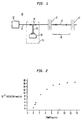
- Fig. 2 is a graphical illustration showing the signal from the pump monitor 11 as a function of diode output power.
- the fluorescence signal is proportional to ytterbium concentration. At some pump level, the fluorescence signal saturates. The saturation intensity can be increased by adding dopant ions that quench fluorescence, thereby decreasing the fluorescence lifetime and making more ions available in the ground state.
- non-linear effects such as cooperative upconversion or energy transfer to a second dopant ion where light is emitted could also be utilized. These have potential advantages in that the emission may be a super-linear function of pump power and, therefore, more sensitive to changes in launched pump light. Moreover, the wavelength of the emitted light may make it easier to filter out the scattered pump light.
- the indicator waveguide 18 is doped with an absorbing impurity such as a transition element: advantageously V, Cr, Mn, Fe, Co, Ni or Cu. Fe is preferred.
- Detector 19 is a heat detector thermally coupled to the indicator waveguide 18. The heat generated in the core is proportional to the pump power flowing in the core.
- a useful heat detector for this application is a thermocouple.
- Fig. 1 can be used for any waveguide laser or amplifier and is not restricted to fiber devices or to cladding pumped devices. Numerous and varied other arrangements can be made by those skilled in the art without departing from the scope of the invention.
Landscapes
- Physics & Mathematics (AREA)
- Electromagnetism (AREA)
- Engineering & Computer Science (AREA)
- Plasma & Fusion (AREA)
- Optics & Photonics (AREA)
- Lasers (AREA)
- Light Guides In General And Applications Therefor (AREA)
Applications Claiming Priority (2)
| Application Number | Priority Date | Filing Date | Title |
|---|---|---|---|
| US303383 | 1999-04-30 | ||
| US09/303,383 US6389186B1 (en) | 1999-04-30 | 1999-04-30 | Optical waveguide lasers and amplifiers with pump power monitors |
Publications (2)
| Publication Number | Publication Date |
|---|---|
| EP1049219A2 true EP1049219A2 (de) | 2000-11-02 |
| EP1049219A3 EP1049219A3 (de) | 2003-10-08 |
Family
ID=23171841
Family Applications (1)
| Application Number | Title | Priority Date | Filing Date |
|---|---|---|---|
| EP00303399A Withdrawn EP1049219A3 (de) | 1999-04-30 | 2000-04-20 | Wellenleiterlaser mit Pumpleistungsmonitor |
Country Status (3)
| Country | Link |
|---|---|
| US (1) | US6389186B1 (de) |
| EP (1) | EP1049219A3 (de) |
| JP (1) | JP3808689B2 (de) |
Cited By (1)
| Publication number | Priority date | Publication date | Assignee | Title |
|---|---|---|---|---|
| JP2009206209A (ja) * | 2008-02-26 | 2009-09-10 | Fujitsu Ltd | 光ファイバ増幅器、劣化検出器および劣化検出方法 |
Families Citing this family (18)
| Publication number | Priority date | Publication date | Assignee | Title |
|---|---|---|---|---|
| WO2001099243A1 (de) * | 2000-06-20 | 2001-12-27 | Evotec Oai Ag | Faser-laser |
| US7525654B2 (en) * | 2004-10-20 | 2009-04-28 | Duquesne University Of The Holy Spirit | Tunable laser-based chemical imaging system |
| US7371019B2 (en) * | 2004-12-13 | 2008-05-13 | Nufern | Method and apparatus for sensing light |
| US9976192B2 (en) | 2006-03-10 | 2018-05-22 | Ldip, Llc | Waveguide-based detection system with scanning light source |
| US8288157B2 (en) * | 2007-09-12 | 2012-10-16 | Plc Diagnostics, Inc. | Waveguide-based optical scanning systems |
| US7951583B2 (en) * | 2006-03-10 | 2011-05-31 | Plc Diagnostics, Inc. | Optical scanning system |
| US9528939B2 (en) | 2006-03-10 | 2016-12-27 | Indx Lifecare, Inc. | Waveguide-based optical scanning systems |
| US9423397B2 (en) | 2006-03-10 | 2016-08-23 | Indx Lifecare, Inc. | Waveguide-based detection system with scanning light source |
| EP2003745A4 (de) * | 2006-03-31 | 2011-04-20 | Furukawa Electric Co Ltd | Lichtquelle |
| US7515780B2 (en) | 2006-10-25 | 2009-04-07 | Alcatel-Lucent Usa Inc. | System and method for fabricating an optical isolator |
| GB2461026B (en) * | 2008-06-16 | 2011-03-09 | Plc Diagnostics Inc | System and method for nucleic acids sequencing by phased synthesis |
| WO2010127001A1 (en) * | 2009-04-29 | 2010-11-04 | Plc Diagnostics Inc. | Waveguide-based detection system with scanning light source |
| US8982452B2 (en) * | 2009-05-11 | 2015-03-17 | Ofs Fitel, Llc | All-in-one raman fiber laser |
| JP5680170B1 (ja) * | 2013-11-14 | 2015-03-04 | 株式会社フジクラ | ファイバレーザ装置 |
| US10018566B2 (en) | 2014-02-28 | 2018-07-10 | Ldip, Llc | Partially encapsulated waveguide based sensing chips, systems and methods of use |
| US11181479B2 (en) | 2015-02-27 | 2021-11-23 | Ldip, Llc | Waveguide-based detection system with scanning light source |
| JP6363680B2 (ja) * | 2016-11-16 | 2018-07-25 | ファナック株式会社 | レーザ装置 |
| EP3622593A4 (de) * | 2017-05-08 | 2021-01-06 | Lawrence Livermore National Security, LLC | Skalierung von hochenergetischen gepulsten festkörperlasern auf hohe durchschnittliche leistung |
Family Cites Families (3)
| Publication number | Priority date | Publication date | Assignee | Title |
|---|---|---|---|---|
| JPS585010U (ja) * | 1981-07-02 | 1983-01-13 | 住友電気工業株式会社 | 導光用フアイバに出力レ−ザ光を通すレ−ザ機器のモニタ装置 |
| US5504762A (en) * | 1994-10-11 | 1996-04-02 | Spectra-Physics Lasers, Inc. | Laser diode system with feedback control |
| EP0886174A3 (de) * | 1997-06-18 | 2001-03-07 | Nippon Telegraph And Telephone Corporation | Gepulste Weisslichtquelle |
-
1999
- 1999-04-30 US US09/303,383 patent/US6389186B1/en not_active Expired - Lifetime
-
2000
- 2000-04-20 EP EP00303399A patent/EP1049219A3/de not_active Withdrawn
- 2000-04-28 JP JP2000130598A patent/JP3808689B2/ja not_active Expired - Fee Related
Cited By (1)
| Publication number | Priority date | Publication date | Assignee | Title |
|---|---|---|---|---|
| JP2009206209A (ja) * | 2008-02-26 | 2009-09-10 | Fujitsu Ltd | 光ファイバ増幅器、劣化検出器および劣化検出方法 |
Also Published As
| Publication number | Publication date |
|---|---|
| JP3808689B2 (ja) | 2006-08-16 |
| JP2000323769A (ja) | 2000-11-24 |
| US6389186B1 (en) | 2002-05-14 |
| EP1049219A3 (de) | 2003-10-08 |
Similar Documents
| Publication | Publication Date | Title |
|---|---|---|
| US6389186B1 (en) | Optical waveguide lasers and amplifiers with pump power monitors | |
| JP4071281B2 (ja) | 光ファイバジャイロスコープの光源波長制御 | |
| EP3070791B1 (de) | Faserlaservorrichtung | |
| JP2640588B2 (ja) | 干渉計、その製造および感知方法 | |
| Maurice et al. | High dynamic range temperature point sensor using green fluorescence intensity ratio in erbium-doped silica fiber | |
| EP1639679B1 (de) | Optische vorrichtung | |
| US6456637B1 (en) | Waveguide lasers and optical amplifiers having enhanced thermal stability | |
| Fesler et al. | Stable fiber-source gyroscopes | |
| US5442479A (en) | Fiber-optic amplifier with a facility for monitoring the pump power and input power | |
| KR940005756B1 (ko) | 광섬유 원격 통신회선용 증폭기 및 이 증폭기를 합체하는 광섬유 원격통신회선 | |
| Kang et al. | FBG-referenced interrogating system using a double-ring erbium-doped fiber laser for high power and broadband | |
| AU647069B2 (en) | Integrated optical signal amplifier | |
| US20030215241A1 (en) | Raman optical fiber amplifier using erbium doped fiber | |
| US20010022884A1 (en) | C-band multimode cladding optical fiber amplifier | |
| WO2000035058A2 (en) | Polarization and wavelength stable superfluorescent sources | |
| US6424663B1 (en) | Power monitor for fiber gain medium | |
| KR20000027961A (ko) | 어븀이온 및 툴륨이온이 공동 첨가된 코어를 이용한 광소자 | |
| Liu et al. | Superfluorescent single mode Nd: fiber source at 1060 nm | |
| USH1426H (en) | Apparatus and method for determining the optical power passing through an optical fiber | |
| Castrellon-Uribe et al. | Radiometric analysis of a fiber optic temperature sensor | |
| JP3217841B2 (ja) | 光ファイバセンサ | |
| Grattan et al. | Luminescent optical fibers in sensing | |
| JP2890654B2 (ja) | 分布型光ファイバー温度センサー | |
| Broer et al. | Studying pump light-induced darkening in erbium-doped fiber amplifiers with optical time domain reflectometry | |
| JP3446998B2 (ja) | 1.3μm帯の光増幅器またはレーザー発振器の励起方法 |
Legal Events
| Date | Code | Title | Description |
|---|---|---|---|
| PUAI | Public reference made under article 153(3) epc to a published international application that has entered the european phase |
Free format text: ORIGINAL CODE: 0009012 |
|
| AK | Designated contracting states |
Kind code of ref document: A2 Designated state(s): AT BE CH CY DE DK ES FI FR GB GR IE IT LI LU MC NL PT SE |
|
| AX | Request for extension of the european patent |
Free format text: AL;LT;LV;MK;RO;SI |
|
| PUAL | Search report despatched |
Free format text: ORIGINAL CODE: 0009013 |
|
| AK | Designated contracting states |
Kind code of ref document: A3 Designated state(s): AT BE CH CY DE DK ES FI FR GB GR IE IT LI LU MC NL PT SE |
|
| AX | Request for extension of the european patent |
Extension state: AL LT LV MK RO SI |
|
| AKX | Designation fees paid | ||
| REG | Reference to a national code |
Ref country code: DE Ref legal event code: 8566 |
|
| STAA | Information on the status of an ep patent application or granted ep patent |
Free format text: STATUS: THE APPLICATION IS DEEMED TO BE WITHDRAWN |
|
| 18D | Application deemed to be withdrawn |
Effective date: 20040409 |