EP1048948A1 - Procédé de commande du chauffage d'un capteur électrochimique pour l'analyse des gaz d'échappement d'un moteur à combustion de véhicule - Google Patents
Procédé de commande du chauffage d'un capteur électrochimique pour l'analyse des gaz d'échappement d'un moteur à combustion de véhicule Download PDFInfo
- Publication number
- EP1048948A1 EP1048948A1 EP00401109A EP00401109A EP1048948A1 EP 1048948 A1 EP1048948 A1 EP 1048948A1 EP 00401109 A EP00401109 A EP 00401109A EP 00401109 A EP00401109 A EP 00401109A EP 1048948 A1 EP1048948 A1 EP 1048948A1
- Authority
- EP
- European Patent Office
- Prior art keywords
- sensor
- heating
- temperature
- mode
- combustion engine
- Prior art date
- Legal status (The legal status is an assumption and is not a legal conclusion. Google has not performed a legal analysis and makes no representation as to the accuracy of the status listed.)
- Granted
Links
- 238000000034 method Methods 0.000 title claims abstract description 10
- 238000002485 combustion reaction Methods 0.000 title claims abstract description 5
- 238000004868 gas analysis Methods 0.000 title 1
- 238000010438 heat treatment Methods 0.000 claims abstract description 49
- 239000007789 gas Substances 0.000 claims abstract description 23
- 231100000572 poisoning Toxicity 0.000 claims abstract description 13
- 230000000607 poisoning effect Effects 0.000 claims abstract description 13
- 239000003792 electrolyte Substances 0.000 claims abstract description 5
- 238000005259 measurement Methods 0.000 claims abstract description 5
- 230000002265 prevention Effects 0.000 claims description 2
- 210000004027 cell Anatomy 0.000 description 8
- 230000015556 catabolic process Effects 0.000 description 6
- 238000006731 degradation reaction Methods 0.000 description 6
- 230000004044 response Effects 0.000 description 6
- QVGXLLKOCUKJST-UHFFFAOYSA-N atomic oxygen Chemical compound [O] QVGXLLKOCUKJST-UHFFFAOYSA-N 0.000 description 5
- 229910052760 oxygen Inorganic materials 0.000 description 5
- 239000001301 oxygen Substances 0.000 description 5
- 239000000523 sample Substances 0.000 description 4
- 239000013626 chemical specie Substances 0.000 description 2
- 229930195733 hydrocarbon Natural products 0.000 description 2
- 150000002430 hydrocarbons Chemical class 0.000 description 2
- BASFCYQUMIYNBI-UHFFFAOYSA-N platinum Chemical compound [Pt] BASFCYQUMIYNBI-UHFFFAOYSA-N 0.000 description 2
- 239000000126 substance Substances 0.000 description 2
- 239000004215 Carbon black (E152) Substances 0.000 description 1
- 229910010413 TiO 2 Inorganic materials 0.000 description 1
- 230000032683 aging Effects 0.000 description 1
- 239000003054 catalyst Substances 0.000 description 1
- 229910052729 chemical element Inorganic materials 0.000 description 1
- 238000004140 cleaning Methods 0.000 description 1
- 238000003745 diagnosis Methods 0.000 description 1
- 238000010586 diagram Methods 0.000 description 1
- 238000009792 diffusion process Methods 0.000 description 1
- 239000006185 dispersion Substances 0.000 description 1
- 239000000463 material Substances 0.000 description 1
- 239000000203 mixture Substances 0.000 description 1
- 230000003647 oxidation Effects 0.000 description 1
- 238000007254 oxidation reaction Methods 0.000 description 1
- 229910052697 platinum Inorganic materials 0.000 description 1
- 230000008569 process Effects 0.000 description 1
- 238000005086 pumping Methods 0.000 description 1
- 230000009467 reduction Effects 0.000 description 1
- 230000035945 sensitivity Effects 0.000 description 1
- 238000012163 sequencing technique Methods 0.000 description 1
- 239000007787 solid Substances 0.000 description 1
- 238000001179 sorption measurement Methods 0.000 description 1
Images
Classifications
-
- G—PHYSICS
- G01—MEASURING; TESTING
- G01N—INVESTIGATING OR ANALYSING MATERIALS BY DETERMINING THEIR CHEMICAL OR PHYSICAL PROPERTIES
- G01N27/00—Investigating or analysing materials by the use of electric, electrochemical, or magnetic means
- G01N27/26—Investigating or analysing materials by the use of electric, electrochemical, or magnetic means by investigating electrochemical variables; by using electrolysis or electrophoresis
- G01N27/403—Cells and electrode assemblies
- G01N27/406—Cells and probes with solid electrolytes
- G01N27/4067—Means for heating or controlling the temperature of the solid electrolyte
Definitions
- the present invention relates to a sensor electrochemical for the analysis of exhaust gases from a combustion engine fitted in particular to a vehicle automobile.
- the invention relates more particularly to sensors electrochemicals comprising at least one element of heating of the sensitive internal element of the sensor, which provide representative information of the composition physical and / or chemical exhaust gases and which are used for example to control the engine and / or another associated body, in order to allow diagnostic functions or for the implementation of means of exhaust gas pollution control.
- Such an electrochemical sensor generally comprises at least one measuring cell, comprising two electrodes and an electrolyte, which is associated with a heating element. Indeed, the theoretical optimal performances of the sensor are obtained for a specific temperature of depending on the nature of the components of the electrochemical cell.
- the senor is subject to phenomena poisoning and fouling. This results in a bad sensor operation, i.e. degradation of its performance.
- the object of the invention is to propose a method of heating control of a sensor of the type mentioned previously which protects the sensor, or probe, against poisoning and fouling by adapting the temperature of the sensitive internal element, in particular depending on the exhaust gas temperature.
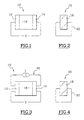
- the sensor 10 shown schematically in the figures 1 and 2 comprises a cell comprising in particular two electrodes 12 and 14 which surround a solid central electrode 16.
- the electrode 12 is for example the reference electrode subjected to air or a gas and the electrode 14 is the electrode of measurement subject to the gas of which one wishes for example to measure the concentration.
- the senor 10 also includes a heating element 18 which is by example an electric resistance supplied by a circuit supply control 20 not shown in detail.
- the heating element 18 is thus for example a platinum resistance whose supply is, in the state of technical, voltage or current controlled so continuous or according to a determined feeding cycle.
- heating control corresponds to a compromise functional aiming in particular to control the aging of the sensor to obtain satisfactory operation of the point of view of its performance over a lifetime determined, this compromise leading to the choice of a mode unique heating.
- the potentiometric type sensor shown in Figure 1 provides a representative electromotive force (fem) V the concentration of the gas to be measured.
- the sensor 10 illustrated in Figures 1 and 2 is for example a sensor of the type used in oxygen probes (LAMBDA, or all or nothing (UEGO or HEGO)).
- a current I called “pumping” is provided by an external system 22 depending on the chemical species to measure.
- This type of sensor is for example used in proportional oxygen sensors (UEGO).
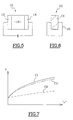
- the third type of sensor 10 represented in FIGS. 5 and 6 is of the resistive type, that is to say that the resistance R at the terminals of the electrodes 12 and 14 is measured, the value of which represents the variation in the concentration of l chemical species to be measured.
- Such a type of sensor is for example used in TiO 2 oxygen probes.
- each cell delivers a signal electric which is characteristic in particular of the pressure partial or chemical elements sought.
- an all-type oxygen sensor or nothing supplied an output voltage V which is a function of the partial pressure of oxygen while in the case of a hydrocarbon gas (HC) sensor, it is a function of the partial pressure of hydrocarbons.
- V which is a function of the partial pressure of oxygen
- HC hydrocarbon gas
- the invention thus proposes to control the heating according to at least two distinct modes of heating.
- the first M1 heating mode of the sensor by example by means of resistor 18, consists in choosing a first determined heating temperature T1 which corresponds to an optimal operating temperature of the sensor from a functional point of view, i.e. at a temperature T1 which optimizes its sensitivity, its stability, its response time and which reduces the dispersion of the measurements.
- the second separate M2 heating mode of the sensor for example by means of resistor 18, consists in choosing a second determined heating temperature T2 which helps prevent poisoning and fouling of the sensor.
- This second temperature of heating T2 for the second heating mode is significantly higher than the temperature Tg of the gases to be measured.
- it must of course be compatible with recommendations for using the sensor and it should not affect its reliability, nor its lifespan.
- the controlled heating process of the sensor according to the invention may also include a third separate mode M3 heating, for example by means of resistor 18 to restore sensor 10 to its performance beforehand altered by poisoning phenomena and / or fouling which can occur in particular during the operation according to the first heating mode M1.
- This third heating mode M3 is carried out at a third determined T3 heating temperature which is notably generally greater than the second temperature T2 for preventing poisoning and / or fouling.
- FIG. 7 shows the response curve C3 of the sensor after it has been subjected to operation comprising a third heating mode M3 for sound descaling, the performance in response of the sensor being then very close to the performance of the new sensor illustrated by curve C1.
- the different modes of controlled heating of the sensor can be selected according to a sequential sequence determined at all times, in particular according to need most urgent or most necessary, this need being analyzed and determined by the electronic unit (not shown) of sensor control.
- the electronic unit of command determines and controls the duration of each mode separate heating and sequential sequencing of modes Mid.
Landscapes
- Chemical & Material Sciences (AREA)
- Life Sciences & Earth Sciences (AREA)
- Health & Medical Sciences (AREA)
- Physics & Mathematics (AREA)
- Chemical Kinetics & Catalysis (AREA)
- Electrochemistry (AREA)
- Molecular Biology (AREA)
- Analytical Chemistry (AREA)
- Biochemistry (AREA)
- General Health & Medical Sciences (AREA)
- General Physics & Mathematics (AREA)
- Immunology (AREA)
- Pathology (AREA)
- Measuring Oxygen Concentration In Cells (AREA)
Abstract
Description
- au moins un premier mode de chauffage du capteur à une première température d'utilisation du capteur, notamment à une température optimale de fonctionnement du capteur ;
- et au moins un deuxième mode distinct de chauffage du capteur à une deuxième température qui est supérieure à la première température d'utilisation et à la température des gaz à analyser, en vue de prévenir l'empoisonnement et/ou l'encrassement du capteur.
- il comporte au moins un troisième mode distinct de chauffage à une troisième température, notamment supérieure à la deuxième température de prévention, en vue de décrasser le capteur pour lui restituer ses performances préalablement altérées ;
- un mode de chauffage peut être mis en oeuvre à des températures différentes ;
- le chauffage du capteur selon lesdits modes distincts de chauffage est effectué selon au moins un cycle prédéterminé de chauffage en fonction des conditions de fonctionnement et/ou d'utilisation du capteur.
- la figure 1 est une vue schématique en coupe transversale d'un premier exemple d'un capteur électrochimique de type potentiométrique ;
- la figure 2 est une vue schématique en coupe transversale selon un autre plan du capteur électrochimique de la figure précédente ;
- les figures 3 et 4 sont des vues similaires à celles des figures 1 et 2 qui illustrent un exemple d'un capteur de type ampèremètrique ;
- les figures 5 et 6 sont des vues similaires à celles des figures 1 et 2 qui illustrent un exemple d'un capteur de type résistif ; et
- la figure 7 est un diagramme illustrant la courbe de réponse électrique d'un capteur potentiométrique, en fonction de la concentration du gaz à mesurer, pour différents états du capteur.
Claims (4)
- Procédé de commande du chauffage d'un capteur électrochimique (10) pour l'analyse des gaz d'échappement d'un moteur à combustion de véhicule, notamment du type comportant au moins une cellule de mesure comprenant deux électrodes (14, 16) et un électrolyte, et qui est associée à un élément de chauffage (18), caractérisé en ce qu'il comporte :au moins un premier mode (M1) de chauffage du capteur (10) à une première température (T1) d'utilisation du capteur, notamment à une température optimale de fonctionnement du capteur ;et au moins un deuxième mode (M2) distinct de chauffage du capteur à une deuxième température (T2)qui est supérieure à la première température (T1) d'utilisation et à la température (Tg) des gaz à analyser, en vue de prévenir l'empoisonnement et/ou l'encrassement du capteur.
- Procédé selon la revendication précédente, caractérisé en ce qu'il comporte au moins un troisième mode (M3) distinct de chauffage à une troisième température (T3), notamment supérieure à la deuxième température (T2) de prévention, en vue de décrasser le capteur (10) pour lui restituer ses performances préalablement altérées
- Procédé selon l'une quelconque des revendications précédentes, caractérisé en ce qu'un mode de chauffage (Mi) peut être mis en oeuvre à des températures (Ti) différentes.
- Procédé selon l'une quelconque des revendications précédentes, caractérisé en ce que le chauffage du capteur (10) selon lesdits modes distincts (Mi) de chauffage est effectué selon au moins un cycle prédéterminé de chauffage en fonction des conditions de fonctionnement et/ou d'utilisation du capteur.
Applications Claiming Priority (2)
| Application Number | Priority Date | Filing Date | Title |
|---|---|---|---|
| FR9905475A FR2793027B1 (fr) | 1999-04-29 | 1999-04-29 | Procede de commande du chauffage d'un capteur electrochimique pour l'analyse des gaz d'echappement d'un moteur a combustion de vehicule |
| FR9905475 | 1999-04-29 |
Publications (2)
| Publication Number | Publication Date |
|---|---|
| EP1048948A1 true EP1048948A1 (fr) | 2000-11-02 |
| EP1048948B1 EP1048948B1 (fr) | 2008-08-13 |
Family
ID=9545052
Family Applications (1)
| Application Number | Title | Priority Date | Filing Date |
|---|---|---|---|
| EP00401109A Expired - Lifetime EP1048948B1 (fr) | 1999-04-29 | 2000-04-20 | Procédé de commande du chauffage d'un capteur électrochimique pour l'analyse des gaz d'échappement d'un moteur à combustion de véhicule |
Country Status (3)
| Country | Link |
|---|---|
| EP (1) | EP1048948B1 (fr) |
| DE (1) | DE60039812D1 (fr) |
| FR (1) | FR2793027B1 (fr) |
Cited By (2)
| Publication number | Priority date | Publication date | Assignee | Title |
|---|---|---|---|---|
| FR2825152A1 (fr) * | 2001-05-22 | 2002-11-29 | Bosch Gmbh Robert | Montage d'electrodes, notamment destine a etre integre dans une conduite de gaz d'echappement |
| WO2008031673A1 (fr) * | 2006-09-14 | 2008-03-20 | Robert Bosch Gmbh | Capteur de gaz, en particulier sonde lambda pour véhicules à moteur à combustion interne |
Citations (3)
| Publication number | Priority date | Publication date | Assignee | Title |
|---|---|---|---|---|
| US5134080A (en) * | 1983-09-06 | 1992-07-28 | Arizona Instrument Corp. | Fluid component detection method |
| EP0695983A2 (fr) * | 1994-08-05 | 1996-02-07 | Nippondenso Co., Ltd. | Appareil de commande d'élément chauffant pour une sonde à oxygène |
| US5696313A (en) * | 1995-04-14 | 1997-12-09 | Haefele; Edelbert | Lambda sensor with electric heater |
Family Cites Families (2)
| Publication number | Priority date | Publication date | Assignee | Title |
|---|---|---|---|---|
| US4938861A (en) * | 1989-08-01 | 1990-07-03 | Kabushiki Kaisha Riken | Limiting current-type oxygen sensor |
| FR2735866B1 (fr) * | 1995-06-22 | 1997-08-29 | Crevoiserat Jean Michel | Sonde pour mesurer la pression partielle d'oxygene dans les cheminees domestiques et industrielles |
-
1999
- 1999-04-29 FR FR9905475A patent/FR2793027B1/fr not_active Expired - Fee Related
-
2000
- 2000-04-20 EP EP00401109A patent/EP1048948B1/fr not_active Expired - Lifetime
- 2000-04-20 DE DE60039812T patent/DE60039812D1/de not_active Expired - Lifetime
Patent Citations (3)
| Publication number | Priority date | Publication date | Assignee | Title |
|---|---|---|---|---|
| US5134080A (en) * | 1983-09-06 | 1992-07-28 | Arizona Instrument Corp. | Fluid component detection method |
| EP0695983A2 (fr) * | 1994-08-05 | 1996-02-07 | Nippondenso Co., Ltd. | Appareil de commande d'élément chauffant pour une sonde à oxygène |
| US5696313A (en) * | 1995-04-14 | 1997-12-09 | Haefele; Edelbert | Lambda sensor with electric heater |
Cited By (5)
| Publication number | Priority date | Publication date | Assignee | Title |
|---|---|---|---|---|
| FR2825152A1 (fr) * | 2001-05-22 | 2002-11-29 | Bosch Gmbh Robert | Montage d'electrodes, notamment destine a etre integre dans une conduite de gaz d'echappement |
| GB2379986A (en) * | 2001-05-22 | 2003-03-26 | Bosch Gmbh Robert | Electrode arrangement and method of use |
| GB2379986B (en) * | 2001-05-22 | 2004-03-10 | Bosch Gmbh Robert | Electrode arrangement |
| US6949874B2 (en) | 2001-05-22 | 2005-09-27 | Robert Bosch Gmbh | Electrode system |
| WO2008031673A1 (fr) * | 2006-09-14 | 2008-03-20 | Robert Bosch Gmbh | Capteur de gaz, en particulier sonde lambda pour véhicules à moteur à combustion interne |
Also Published As
| Publication number | Publication date |
|---|---|
| FR2793027A1 (fr) | 2000-11-03 |
| DE60039812D1 (de) | 2008-09-25 |
| EP1048948B1 (fr) | 2008-08-13 |
| FR2793027B1 (fr) | 2001-09-07 |
Similar Documents
| Publication | Publication Date | Title |
|---|---|---|
| US4543176A (en) | Oxygen concentration detector under temperature control | |
| EP1239282B1 (fr) | Capteur de gaz et méthode pour le chauffer | |
| JP2885336B2 (ja) | 被測定ガス中のNOx濃度の測定方法及び測定装置 | |
| US5763763A (en) | Method and sensing device for measuring predetermined gas component in measurement gas | |
| US5893968A (en) | Method and apparatus for measuring combustible gas component by burning the component | |
| US10914696B2 (en) | Gas-sensor diagnosing method | |
| US6240722B1 (en) | Method for determining the fullness or quality of a catalytic converter that stores gases | |
| US20030116448A1 (en) | Gas sensor element, production method, and reconditioning method thereof | |
| US6266993B1 (en) | Method for testing a measuring sensor | |
| FR2817966A1 (fr) | Detecteur de gaz multicouches et systeme associe de detection de concentration de gaz | |
| KR20150081287A (ko) | 펌프 셀을 포함하는 고체 전해질 센서 소자의 작동 방법 | |
| JP2001505311A (ja) | ガスセンサ | |
| EP0011530B1 (fr) | Capteur électrochimique des concentrations relatives d'espèces réactives dans un mélange de fluide, procédé de fabrication d'un tel capteur et système comportant un tel capteur, notamment pour la régulation | |
| US5772965A (en) | Method and system for detecting deterioration of exhaust gas control catalyst | |
| JPH10185866A (ja) | ガスセンサ | |
| US20030047452A1 (en) | Gas sensor and method of manufacturing the same | |
| EP1048948B1 (fr) | Procédé de commande du chauffage d'un capteur électrochimique pour l'analyse des gaz d'échappement d'un moteur à combustion de véhicule | |
| JP4175767B2 (ja) | ガス分析計およびその校正方法 | |
| JP4625261B2 (ja) | ガスセンサのセンサ素子 | |
| US4666566A (en) | Method of detecting oxygen partial pressure | |
| JPH11352096A (ja) | ガスセンサ素子 | |
| JP4542951B2 (ja) | ガスセンサの評価方法及びガスセンサの評価装置 | |
| US9255904B2 (en) | Step-change sensor for pumped and unpumped operation | |
| JP2004212145A (ja) | ガスセンサの診断装置 | |
| JP3371358B2 (ja) | 酸素ガス・一酸化炭素ガスセンサ、酸素・一酸化炭素測定装置及び酸素・一酸化炭素測定方法 |
Legal Events
| Date | Code | Title | Description |
|---|---|---|---|
| PUAI | Public reference made under article 153(3) epc to a published international application that has entered the european phase |
Free format text: ORIGINAL CODE: 0009012 |
|
| AK | Designated contracting states |
Kind code of ref document: A1 Designated state(s): BE DE |
|
| AX | Request for extension of the european patent |
Free format text: AL;LT;LV;MK;RO;SI |
|
| 17P | Request for examination filed |
Effective date: 20010425 |
|
| AKX | Designation fees paid |
Free format text: BE DE |
|
| RAP1 | Party data changed (applicant data changed or rights of an application transferred) |
Owner name: RENAULT S.A.S. |
|
| 17Q | First examination report despatched |
Effective date: 20071026 |
|
| GRAP | Despatch of communication of intention to grant a patent |
Free format text: ORIGINAL CODE: EPIDOSNIGR1 |
|
| GRAS | Grant fee paid |
Free format text: ORIGINAL CODE: EPIDOSNIGR3 |
|
| GRAA | (expected) grant |
Free format text: ORIGINAL CODE: 0009210 |
|
| AK | Designated contracting states |
Kind code of ref document: B1 Designated state(s): BE DE |
|
| REF | Corresponds to: |
Ref document number: 60039812 Country of ref document: DE Date of ref document: 20080925 Kind code of ref document: P |
|
| PLBE | No opposition filed within time limit |
Free format text: ORIGINAL CODE: 0009261 |
|
| STAA | Information on the status of an ep patent application or granted ep patent |
Free format text: STATUS: NO OPPOSITION FILED WITHIN TIME LIMIT |
|
| 26N | No opposition filed |
Effective date: 20090514 |
|
| BERE | Be: lapsed |
Owner name: RENAULT S.A.S. Effective date: 20090430 |
|
| PG25 | Lapsed in a contracting state [announced via postgrant information from national office to epo] |
Ref country code: BE Free format text: LAPSE BECAUSE OF NON-PAYMENT OF DUE FEES Effective date: 20090430 |
|
| PGFP | Annual fee paid to national office [announced via postgrant information from national office to epo] |
Ref country code: DE Payment date: 20150421 Year of fee payment: 16 |
|
| REG | Reference to a national code |
Ref country code: DE Ref legal event code: R119 Ref document number: 60039812 Country of ref document: DE |
|
| PG25 | Lapsed in a contracting state [announced via postgrant information from national office to epo] |
Ref country code: DE Free format text: LAPSE BECAUSE OF NON-PAYMENT OF DUE FEES Effective date: 20161101 |