EP1048585B1 - Tamper-indicating closure with drainage features - Google Patents
Tamper-indicating closure with drainage features Download PDFInfo
- Publication number
- EP1048585B1 EP1048585B1 EP00303388A EP00303388A EP1048585B1 EP 1048585 B1 EP1048585 B1 EP 1048585B1 EP 00303388 A EP00303388 A EP 00303388A EP 00303388 A EP00303388 A EP 00303388A EP 1048585 B1 EP1048585 B1 EP 1048585B1
- Authority
- EP
- European Patent Office
- Prior art keywords
- flange
- closure
- lugs
- base
- set forth
- Prior art date
- Legal status (The legal status is an assumption and is not a legal conclusion. Google has not performed a legal analysis and makes no representation as to the accuracy of the status listed.)
- Expired - Lifetime
Links
Images

Classifications
-
- B—PERFORMING OPERATIONS; TRANSPORTING
- B65—CONVEYING; PACKING; STORING; HANDLING THIN OR FILAMENTARY MATERIAL
- B65D—CONTAINERS FOR STORAGE OR TRANSPORT OF ARTICLES OR MATERIALS, e.g. BAGS, BARRELS, BOTTLES, BOXES, CANS, CARTONS, CRATES, DRUMS, JARS, TANKS, HOPPERS, FORWARDING CONTAINERS; ACCESSORIES, CLOSURES, OR FITTINGS THEREFOR; PACKAGING ELEMENTS; PACKAGES
- B65D41/00—Caps, e.g. crown caps or crown seals, i.e. members having parts arranged for engagement with the external periphery of a neck or wall defining a pouring opening or discharge aperture; Protective cap-like covers for closure members, e.g. decorative covers of metal foil or paper
- B65D41/32—Caps or cap-like covers with lines of weakness, tearing-strips, tags, or like opening or removal devices, e.g. to facilitate formation of pouring openings
- B65D41/34—Threaded or like caps or cap-like covers provided with tamper elements formed in, or attached to, the closure skirt
-
- B—PERFORMING OPERATIONS; TRANSPORTING
- B65—CONVEYING; PACKING; STORING; HANDLING THIN OR FILAMENTARY MATERIAL
- B65D—CONTAINERS FOR STORAGE OR TRANSPORT OF ARTICLES OR MATERIALS, e.g. BAGS, BARRELS, BOTTLES, BOXES, CANS, CARTONS, CRATES, DRUMS, JARS, TANKS, HOPPERS, FORWARDING CONTAINERS; ACCESSORIES, CLOSURES, OR FITTINGS THEREFOR; PACKAGING ELEMENTS; PACKAGES
- B65D41/00—Caps, e.g. crown caps or crown seals, i.e. members having parts arranged for engagement with the external periphery of a neck or wall defining a pouring opening or discharge aperture; Protective cap-like covers for closure members, e.g. decorative covers of metal foil or paper
- B65D41/02—Caps or cap-like covers without lines of weakness, tearing strips, tags, or like opening or removal devices
- B65D41/04—Threaded or like caps or cap-like covers secured by rotation
- B65D41/0471—Threaded or like caps or cap-like covers secured by rotation with means for positioning the cap on the container, or for limiting the movement of the cap, or for preventing accidental loosening of the cap
-
- B—PERFORMING OPERATIONS; TRANSPORTING
- B65—CONVEYING; PACKING; STORING; HANDLING THIN OR FILAMENTARY MATERIAL
- B65D—CONTAINERS FOR STORAGE OR TRANSPORT OF ARTICLES OR MATERIALS, e.g. BAGS, BARRELS, BOTTLES, BOXES, CANS, CARTONS, CRATES, DRUMS, JARS, TANKS, HOPPERS, FORWARDING CONTAINERS; ACCESSORIES, CLOSURES, OR FITTINGS THEREFOR; PACKAGING ELEMENTS; PACKAGES
- B65D41/00—Caps, e.g. crown caps or crown seals, i.e. members having parts arranged for engagement with the external periphery of a neck or wall defining a pouring opening or discharge aperture; Protective cap-like covers for closure members, e.g. decorative covers of metal foil or paper
- B65D41/02—Caps or cap-like covers without lines of weakness, tearing strips, tags, or like opening or removal devices
- B65D41/04—Threaded or like caps or cap-like covers secured by rotation
- B65D41/0435—Threaded or like caps or cap-like covers secured by rotation with separate sealing elements
- B65D41/045—Discs
-
- B—PERFORMING OPERATIONS; TRANSPORTING
- B65—CONVEYING; PACKING; STORING; HANDLING THIN OR FILAMENTARY MATERIAL
- B65D—CONTAINERS FOR STORAGE OR TRANSPORT OF ARTICLES OR MATERIALS, e.g. BAGS, BARRELS, BOTTLES, BOXES, CANS, CARTONS, CRATES, DRUMS, JARS, TANKS, HOPPERS, FORWARDING CONTAINERS; ACCESSORIES, CLOSURES, OR FITTINGS THEREFOR; PACKAGING ELEMENTS; PACKAGES
- B65D41/00—Caps, e.g. crown caps or crown seals, i.e. members having parts arranged for engagement with the external periphery of a neck or wall defining a pouring opening or discharge aperture; Protective cap-like covers for closure members, e.g. decorative covers of metal foil or paper
- B65D41/32—Caps or cap-like covers with lines of weakness, tearing-strips, tags, or like opening or removal devices, e.g. to facilitate formation of pouring openings
- B65D41/34—Threaded or like caps or cap-like covers provided with tamper elements formed in, or attached to, the closure skirt
- B65D41/3423—Threaded or like caps or cap-like covers provided with tamper elements formed in, or attached to, the closure skirt with flexible tabs, or elements rotated from a non-engaging to an engaging position, formed on the tamper element or in the closure skirt
- B65D41/3428—Threaded or like caps or cap-like covers provided with tamper elements formed in, or attached to, the closure skirt with flexible tabs, or elements rotated from a non-engaging to an engaging position, formed on the tamper element or in the closure skirt the tamper element being integrally connected to the closure by means of bridges
Definitions
- the present invention relates to tamper-indicating closures, to methods of manufacturing such closures, and to a package that includes such a closure on a container.
- a tamper-indicating closure having a band connected to the skirt of the closure by integral frangible bridges or webs.
- the band has a stop element (e.g., a flange or a bead) that engages a bead on the container to resist unthreading of the closure, so that removal of the closure ruptures the frangible elements that connect the band to the closure skirt.
- U.S. Patent Re 33,265 assigned to the assignee hereof, discloses a tamper-indicating closure of this character, in which the tamper-indicating band is completely severed from the closure skirt and remains with the container upon removal of the closure from the container.
- Patent 5,295,600 also assigned to the assignee hereof, discloses a tamper-indicating closure in which the tamper-indicating band remains connected to the closure skirt and is removed from the container with the closure.
- U.S. Patent 4,470,513 discloses a closure having a tamper-indicating band which comprises a plurality of spaced-apart tabs, each tab connected to its neighbouring tab by way of a flexible web. Each tab has an outwardly extending projection at its lowermost extent.
- the present invention will help alleviate the potential for product entrapment when the product filler finds it necessary to use such a filling process.
- Another and related object of the present invention is to provide a closure and method of manufacture that achieve the foregoing objectives while retaining the advantages of the closures disclosed in the above-noted patents in terms of ease of application to the container finish after filling (lower top load and lower temperature) and whole or partial rupture of the tamper-indicating band from the closure skirt to provide the tamper-indicating feature.
- Yet another object of the present invention is to provide a package, which includes a closure and a container, that is particularly well adapted for use in conjunction with wet finish applications as described.
- a tamper-indicating closure of integrally molded plastic construction in accordance with the invention comprises:
- the lugs are thus disposed for opposed abutting engagement with the A1 diameter of the container finish beneath the A bead on the container finish.
- the channels or serrations between the lugs permit drainage of liquid from the area between the skirt and the container finish.
- the lugs are of uniform dimension circumferentially of the flange, and spacing between the lugs is of uniform dimension circumferentially of the flange.
- the uniform circumferential dimension of the lugs is preferably less than the uniform circumferential spacing between the lugs to enhance the area for drainage of liquid between the flange and the opposing surface of the container finish,
- the lugs thus serve to space the flange base from the container finish, and to strengthen the flange base upon abutting engagement with the finish A bead during removal of the closure from the container finish.
- the thickness of the lugs at the free edge of the flange may be either greater than or less than the thickness of the base at the free edge of the flange.
- Thickness of the flange base may be either uniform axially and radially of the flange, or may increase axially and radially of the flange from the band to the free edge of the flange.
- the free edge of the flange preferably is circumferentially continuous without scallops or indentation, and lies entirely in a plane parallel to the base wall.
- a package is provided that comprises the closure of any of claims 1 to 13 in combination with a container having a finish with an external thread on which said closure is received and an external bead for cooperation with said flange.
- FIGS. 1-3 illustrate a package 20 in accordance with one presently preferred embodiment of the invention as comprising a container 22 of glass or molded plastic construction and a tamper-indicating closure 24 threaded thereon.
- Container 22 has an axially extending finish 26 for receiving closure 24.
- Closure 24 has a flat base wall 30 on which a sealing liner 32 is secured.
- An annular peripheral skirt 34 extends downwardly from closure base wall 30, and has an internal thread 36 for securing closure 24 over an external thread 28 on container 22.
- a tamper-indicating band 38 is secured to the lower end of skirt 34, being separated therefrom by a circumferential score 40. Tamper-indicating band 38 is coupled to closure skirt 34 by a circumferentially spaced array of frangible bridges 41 (FIGS. 2 and 3). Bridges 41 preferably are formed during the scoring operation, as described in patents referenced hereinafter. Alternatively, the bridges may be molded onto the inside surface of skirt 34 and band 38, as shown in U.S. Patents 4,407,422 and 4,418,828. Alternatively, but less preferably, band 38 may be connected to skirt 34 by one or more thin frangible webs integrally molded with the closure.
- a stop flange 42 extends radially inwardly and axially upwardly (FIG. 2) from the lower end of band 38 to a position beneath a radially outwardly extending bead 45 on container 22 beneath threads 28.
- Bead 45 is sometimes called the container transfer bead or the A bead, referring to the fact that bead 45 defines the A dimension of the container finish.
- Closure 24 may be injection molded, or may be compression molded as taught in U.S. Patent 5,554,327.
- Liner 32 may be separately formed, or more preferably compression molded in situ within a preformed closure as disclosed in U.S. Patents 4,984,703 and 5,451,360.
- U.S. Patents 5,488,888, 5,522,293 and 5,564,319 disclose techniques for forming score 40 and bridges 41 in the scoring operation.
- U.S. Patents 5,755,347 and Re 33,265 disclose techniques for inverting stop flange 42 from the as-molded configuration of FIG. 3 to the configuration of FIG. 2 ready for use.
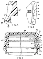
- FIGS. 3-8 illustrate closure 24 as molded -- i.e., before inversion of stop flange 42, formation of score line 40 and molding of liner 32.
- Stop flange 42 in accordance with one aspect of the present invention comprises a circumferentially continuous base 44 on which a plurality of lugs 46 are integrally molded.
- Flange base 44 in the embodiment of FIGS. 1-5 is of uniform thickness both circumferentially of flange 42, and axially of flange 42.
- Lugs 46 are of identical and uniform circumferential dimension as best seen in FIGS.
- circumferentially spacing between lugs 46 preferably is greater than the circumferential dimension of lugs 46.
- Lugs 46 serve not only to space flange base 44 from the container finish as will be described, but also to strengthen the flange 42 during abutting engagement with finish bead 45 during frangible separation of band 38 from skirt 34. It is presently preferred that lugs 46 occupy minimum circumferential dimension of flange 42 consistent with this strengthening function.
- lugs 46 are urged by internal resiliency of the closure material into opposed abutting engagement with the opposing surface at the so-called A1 diameter of the container finish beneath bead 45.
- the circumferentially spaced lugs 46 thus serve to space base 44 of flange 42 radially outwardly from the opposed container finish surface, thereby providing intervening serrations or channels for drainage of liquid that might otherwise be captured between the closure skirt and the container finish.
- the spaced lugs 46 thus function to form serrations or channels between the lugs for drainage of liquid.
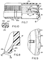
- FIGS. 6-10 illustrate a closure/container package 50 in accordance with another embodiment of the invention. Elements in FIGS. 6-10 that are identical or similar to elements in the embodiment of FIGS. 1-5 are indicated by correspondingly identical reference numerals, while modified elements are indicated by corresponding reference numerals followed by the suffix "a.”
- Closure 52 in package 50 includes a base wall 30a and a peripheral skirt 34a.
- a liner 32a is provided on the internal surface of base wall 30a, preferably by compression molding in situ as previously described. Whereas liner 32 in FIG. 2 is of the type illustrated in U.S. Patent Application Serial No. 08/851,821, liner 32a in FIG. 6 is of the type illustrated in U.S. Patent 5,650,113 or 5,265,747.
- closure 24 (FIGS. 1-5) or closure 52 (FIGS. 6-10) may be of the so-called linerless type, embodying a sealing lip as illustrated for example in U.S. Patent 5,320,236.
- a stop flange 42a extends from tamper-indicating band 38 of closure 52.
- flange 42a differs somewhat from flange 42 in FIG. 4 in that flange base 44a is of uniform dimension circumferentially, but thickens or widens axially from tamper-indicating band 38.
- Circumferentially spaced lugs 46a are of uniform and identical circumferential dimension, as are the gaps or spaces between the lugs, and thicken or widen axially and radially from band 38 to the free edge of flange 42a.
- flange 42a in FIGS. 6-8 is stronger than 42 in FIGS. 1-5, but the serrations or channels formed between the lugs 46a are of lesser radial dimension in the embodiment of FIGS. 6-10 than in the embodiment of FIGS. 1-5.
- flange base 44 has a nominal thickness of 0.356 mm (0.014 inches) and a total thickness at the free edge of flange 42 of 0.889 mm (0.035 inches).
- the thickness of lugs 46 increases from zero at band 38 to about 0.533 mm (0.021 inches) at the free edge of the flange.
- the overall axial and radial length of flange 42 is about 1.524 mm (0.060 inches).
- the thickness of flange base 44a at the juncture with band 38 is 0.254 mm (0.010 inches), and the overall thickness at the free edge of flange 42a is 0.889 mm (0.035 inches).
- the overall radial and axial dimension of flange 42a is about 1.727 mm (0.068 inches).
- the thickness of flange base 44a at the free edge of the flange is 0.533 mm (0.021 inches).
- lugs 46a increase from zero thickness adjacent to band 38 to about 0.356 mm (0.014 inches) at the free edge of the flange. All exemplary dimensions are nominal.
- FIGS. 6-10 illustrates another feature or aspect of the present invention.
- Closure 52 is provided with a double internal thread starting 180° apart. Each thread has a circumferential dimension of 250°.
- a pair of diametrically opposed friction ribs 60 extend radially inwardly from the inside surface of closure skirt 34a, and extend axially between adjacent reaches of the internal threads 36a. The radial dimension of ribs 60 is less than half the radial depth of closure threads 36a. In the illustrated embodiment, the circumferential dimension of each rib 60 is 1.524 mm (0.060 inches), and the radial dimension is 0.381 mm (0.015 inches).
- Each rib 60 has rounded circumferential edges for camming engagement with the container threads as closure 52 is threaded onto the finish 26a of container 22a.
- ribs 60 help to maintain frictional engagement between the closure and the container finish as the closure is threaded onto and off of the container. This is particularly useful in conjunction with double-thread closures.
Description
- The present invention relates to tamper-indicating closures, to methods of manufacturing such closures, and to a package that includes such a closure on a container.
- It is conventional to form a tamper-indicating closure having a band connected to the skirt of the closure by integral frangible bridges or webs. The band has a stop element (e.g., a flange or a bead) that engages a bead on the container to resist unthreading of the closure, so that removal of the closure ruptures the frangible elements that connect the band to the closure skirt. U.S. Patent Re 33,265, assigned to the assignee hereof, discloses a tamper-indicating closure of this character, in which the tamper-indicating band is completely severed from the closure skirt and remains with the container upon removal of the closure from the container. U.S. Patent 5,295,600, also assigned to the assignee hereof, discloses a tamper-indicating closure in which the tamper-indicating band remains connected to the closure skirt and is removed from the container with the closure. U.S. Patent 4,470,513 discloses a closure having a tamper-indicating band which comprises a plurality of spaced-apart tabs, each tab connected to its neighbouring tab by way of a flexible web. Each tab has an outwardly extending projection at its lowermost extent.
- Although tamper-indicating closures of the types disclosed in the noted patents have enjoyed substantial commercial acceptance and success in the art, further improvements remain desirable. In particular, problems are encountered when employing this type of closure with a container in so-called wet finish applications, in which liquid may spill during or after the filling operation onto the outside surface of the container finish so as to be disposed between the container finish and the closure skirt after capping. Wet finish situations of this type are encountered during hot-fill, cold-fill and aseptic-fill situations, in which the containers are filled close to the brim or to overflow prior to capping. Wet finish situations can also be encountered during filling operations in which liquid may drip from the filling machinery onto the container finish. In wet-finish situations of this type, problems are encountered in connection with draining and drying of the area between the outer surface of the container finish and the closure skirt - i.e., between the threads on the container finish and skirt, and around the tamper-indicating band and the stop element. Liquid trapped within this area can result in growth of mold and mildew. This drainage problem is particularly exacerbated in situations in which the self resiliency of the closure biases the stop flange into opposed engagement with the so-called A1 diameter of the container finish. While wet finish applications are not usually recommended by closure manufacturers because of the potential for entrapment of product in the closure threads and the consumer problems that result therefrom, the present invention will help alleviate the potential for product entrapment when the product filler finds it necessary to use such a filling process.
- It is a general object of the present invention to provide a closure and method of manufacture that facilitate drainage of liquid products after. Another and related object of the present invention is to provide a closure and method of manufacture that achieve the foregoing objectives while retaining the advantages of the closures disclosed in the above-noted patents in terms of ease of application to the container finish after filling (lower top load and lower temperature) and whole or partial rupture of the tamper-indicating band from the closure skirt to provide the tamper-indicating feature. Yet another object of the present invention is to provide a package, which includes a closure and a container, that is particularly well adapted for use in conjunction with wet finish applications as described.
- A tamper-indicating closure of integrally molded plastic construction in accordance with the invention comprises:
- a base wall having a peripheral skirt with internal means for securing the closure to a container, a tamper-indicating band connected by frangible means to an edge of said skirt, and a stop flange extending axially toward said base and radially inwardly from an edge of said band remote from said skirt, characterized in that
- said stop flange comprises a circumferentially continuous base extending from said band to a free edge of said flange and being of constant cross section circumferentially entirely around said flange, said free edge being circumferentially continuous and lying entirely in a plane parallel to said base wall, and a plurality of circumferentially spaced lugs integral with and extending axially along said base and radially inwardly from said base, said lugs radially thickening uniformly from zero thickness adjacent to said band to a maximum thickness at said free edge of said flange, each of said lugs being of constant cross section circumferentially of said flange.
-
- The lugs are thus disposed for opposed abutting engagement with the A1 diameter of the container finish beneath the A bead on the container finish. The channels or serrations between the lugs permit drainage of liquid from the area between the skirt and the container finish.
- In the preferred embodiments of the invention, the lugs are of uniform dimension circumferentially of the flange, and spacing between the lugs is of uniform dimension circumferentially of the flange. The uniform circumferential dimension of the lugs is preferably less than the uniform circumferential spacing between the lugs to enhance the area for drainage of liquid between the flange and the opposing surface of the container finish, The lugs thus serve to space the flange base from the container finish, and to strengthen the flange base upon abutting engagement with the finish A bead during removal of the closure from the container finish. The thickness of the lugs at the free edge of the flange may be either greater than or less than the thickness of the base at the free edge of the flange. Thickness of the flange base may be either uniform axially and radially of the flange, or may increase axially and radially of the flange from the band to the free edge of the flange. The free edge of the flange preferably is circumferentially continuous without scallops or indentation, and lies entirely in a plane parallel to the base wall.
- In accordance with another aspect of the present invention, a package is provided that comprises the closure of any of claims 1 to 13 in combination with a container having a finish with an external thread on which said closure is received and an external bead for cooperation with said flange.
- In accordance with yet another aspect of the present invention, a method of filling and capping a container, as recited in
claim 15, is provided. - The invention, together with additional objects, features and advantages thereof, will be best understood from the following description, the appended claims and the accompanying drawings in which:
- FIG. 1 is a fragmentary perspective view of a container and closure package in accordance with a presently preferred embodiment of the invention;
- FIG. 2 is a fragmentary sectional view that illustrates the container finish and closure in the package of FIG. 1;
- FIG. 3 is a partially sectioned side elevational view of the closure in the package of FIGS. 1 and 2 as molded - i.e., before stop flange inversion;
- FIG. 4 is a fragmentary sectional view of the portion of the closure
within the
circle 4 in FIG. 3; - FIG. 5 is a fragmentary plan view taken from the direction 5-5 in FIG. 4;
- FIG. 6 is a fragmentary sectional view that bisects a closure and container finish in accordance with another embodiment of the invention;
- FIG. 7 is a partially sectioned side elevational view of the closure in the package of FIG. 6 as molded;
- FIG. 8 is a fragmentary sectional view of the portion of FIG. 7 within
the
circle 8; - FIG. 9 is a fragmentary plan view taken from the direction 9-9 in FIG. 8; and
- FIG. 10 is a fragmentary sectional view taken substantially along the line 10-10 in FIG. 7.
-
- FIGS. 1-3 illustrate a
package 20 in accordance with one presently preferred embodiment of the invention as comprising acontainer 22 of glass or molded plastic construction and a tamper-indicatingclosure 24 threaded thereon.Container 22 has an axially extendingfinish 26 for receivingclosure 24. Closure 24 has aflat base wall 30 on which asealing liner 32 is secured. An annularperipheral skirt 34 extends downwardly fromclosure base wall 30, and has aninternal thread 36 for securingclosure 24 over anexternal thread 28 oncontainer 22. (Direction adjectives such as "downwardly" are taken with reference to the vertical orientation of the container and closure illustrated in FIGS. 1 and 2.) A tamper-indicatingband 38 is secured to the lower end ofskirt 34, being separated therefrom by acircumferential score 40. Tamper-indicatingband 38 is coupled toclosure skirt 34 by a circumferentially spaced array of frangible bridges 41 (FIGS. 2 and 3). Bridges 41 preferably are formed during the scoring operation, as described in patents referenced hereinafter. Alternatively, the bridges may be molded onto the inside surface ofskirt 34 andband 38, as shown in U.S. Patents 4,407,422 and 4,418,828. Alternatively, but less preferably,band 38 may be connected toskirt 34 by one or more thin frangible webs integrally molded with the closure. Astop flange 42 extends radially inwardly and axially upwardly (FIG. 2) from the lower end ofband 38 to a position beneath a radially outwardly extendingbead 45 oncontainer 22 beneaththreads 28.Bead 45 is sometimes called the container transfer bead or the A bead, referring to the fact thatbead 45 defines the A dimension of the container finish. - Closure 24 may be injection molded, or may be compression molded as taught in U.S. Patent 5,554,327.
Liner 32 may be separately formed, or more preferably compression molded in situ within a preformed closure as disclosed in U.S. Patents 4,984,703 and 5,451,360. U.S. Patents 5,488,888, 5,522,293 and 5,564,319 disclose techniques for formingscore 40 andbridges 41 in the scoring operation. U.S. Patents 5,755,347 and Re 33,265 disclose techniques for invertingstop flange 42 from the as-molded configuration of FIG. 3 to the configuration of FIG. 2 ready for use. - FIGS. 3-8 illustrate
closure 24 as molded -- i.e., before inversion ofstop flange 42, formation ofscore line 40 and molding ofliner 32. Stopflange 42 in accordance with one aspect of the present invention comprises a circumferentiallycontinuous base 44 on which a plurality oflugs 46 are integrally molded.Flange base 44 in the embodiment of FIGS. 1-5 is of uniform thickness both circumferentially offlange 42, and axially offlange 42. Thus the radially and axially outer surface ofbase 44 is parallel to the radially and axially inner surface thereof, as best seen in FIG. 4.Lugs 46 are of identical and uniform circumferential dimension as best seen in FIGS. 3 and 5, and widen or thicken axially offlange 42 from zero thickness at the juncture offlange 42 withband 38, to a maximum thickness at the free edge offlange 42. As best seen in FIG. 5, circumferentially spacing betweenlugs 46 preferably is greater than the circumferential dimension oflugs 46.Lugs 46 serve not only tospace flange base 44 from the container finish as will be described, but also to strengthen theflange 42 during abutting engagement withfinish bead 45 during frangible separation ofband 38 fromskirt 34. It is presently preferred that lugs 46 occupy minimum circumferential dimension offlange 42 consistent with this strengthening function. - As best seen in FIG. 2. following inversion of
flange 42 and securement ofclosure 24 tocontainer 22, lugs 46 are urged by internal resiliency of the closure material into opposed abutting engagement with the opposing surface at the so-called A1 diameter of the container finish beneathbead 45. The circumferentially spaced lugs 46 thus serve tospace base 44 offlange 42 radially outwardly from the opposed container finish surface, thereby providing intervening serrations or channels for drainage of liquid that might otherwise be captured between the closure skirt and the container finish. The spaced lugs 46 thus function to form serrations or channels between the lugs for drainage of liquid. - FIGS. 6-10 illustrate a closure/container package 50 in accordance with another embodiment of the invention. Elements in FIGS. 6-10 that are identical or similar to elements in the embodiment of FIGS. 1-5 are indicated by correspondingly identical reference numerals, while modified elements are indicated by corresponding reference numerals followed by the suffix "a."
Closure 52 in package 50 includes abase wall 30a and aperipheral skirt 34a. Aliner 32a is provided on the internal surface ofbase wall 30a, preferably by compression molding in situ as previously described. Whereasliner 32 in FIG. 2 is of the type illustrated in U.S. Patent Application Serial No. 08/851,821,liner 32a in FIG. 6 is of the type illustrated in U.S. Patent 5,650,113 or 5,265,747. It is also contemplated in accordance with the present invention that closure 24 (FIGS. 1-5) or closure 52 (FIGS. 6-10) may be of the so-called linerless type, embodying a sealing lip as illustrated for example in U.S. Patent 5,320,236. Astop flange 42a extends from tamper-indicatingband 38 ofclosure 52. As best seen in FIG. 8,flange 42a differs somewhat fromflange 42 in FIG. 4 in thatflange base 44a is of uniform dimension circumferentially, but thickens or widens axially from tamper-indicatingband 38. Circumferentially spaced lugs 46a are of uniform and identical circumferential dimension, as are the gaps or spaces between the lugs, and thicken or widen axially and radially fromband 38 to the free edge offlange 42a. Thus,flange 42a in FIGS. 6-8 is stronger than 42 in FIGS. 1-5, but the serrations or channels formed between thelugs 46a are of lesser radial dimension in the embodiment of FIGS. 6-10 than in the embodiment of FIGS. 1-5. - In an exemplary 43mm embodiment of the closure illustrated in FIGS. 1-5,
flange base 44 has a nominal thickness of 0.356 mm (0.014 inches) and a total thickness at the free edge offlange 42 of 0.889 mm (0.035 inches). Thus, the thickness oflugs 46 increases from zero atband 38 to about 0.533 mm (0.021 inches) at the free edge of the flange. The overall axial and radial length offlange 42 is about 1.524 mm (0.060 inches). There are thirty-six equally spaced lugs 46 disposed aroundband 44 in this 43 mm closure embodiment, with eachlug 46 having a circumferential dimension of 1.27 mm (0.050 inches). In a 38mm example of the embodiment of the invention illustrated in FIGS. 6-10, the thickness offlange base 44a at the juncture withband 38 is 0.254 mm (0.010 inches), and the overall thickness at the free edge offlange 42a is 0.889 mm (0.035 inches). There are thirty-two equally spacedlugs 46a around the circumference offlange 42a, with each lug having a circumferential thickness of 1.499 mm (0.059 inches). The overall radial and axial dimension offlange 42a is about 1.727 mm (0.068 inches). The thickness offlange base 44a at the free edge of the flange is 0.533 mm (0.021 inches). Thus, lugs 46a increase from zero thickness adjacent to band 38 to about 0.356 mm (0.014 inches) at the free edge of the flange. All exemplary dimensions are nominal. - The embodiment of FIGS. 6-10 illustrates another feature or aspect of the present invention.
Closure 52 is provided with a double internal thread starting 180° apart. Each thread has a circumferential dimension of 250°. A pair of diametrically opposedfriction ribs 60 extend radially inwardly from the inside surface ofclosure skirt 34a, and extend axially between adjacent reaches of theinternal threads 36a. The radial dimension ofribs 60 is less than half the radial depth ofclosure threads 36a. In the illustrated embodiment, the circumferential dimension of eachrib 60 is 1.524 mm (0.060 inches), and the radial dimension is 0.381 mm (0.015 inches). Eachrib 60 has rounded circumferential edges for camming engagement with the container threads asclosure 52 is threaded onto thefinish 26a ofcontainer 22a. Thus,ribs 60 help to maintain frictional engagement between the closure and the container finish as the closure is threaded onto and off of the container. This is particularly useful in conjunction with double-thread closures.
Claims (15)
- A tamper-indicating closure of integrally molded plastic construction, which comprises a base wall (30 or 30a) having a peripheral skirt (34 or 34a) with internal means (36 or 36a) for securing the closure to a container (22 or 22a), a tamper-indicating band (38) connected by frangible means (41) to an edge of said skirt, and a stop flange (42 or 42a) extending axially toward said base wall and radially inwardly from an edge of said band remote from said skirt, characterized in that
said stop flange (42 or 42a) comprises a circumferentially continuous base (44 or 44a) extending from said band (38) to a free edge of said flange and being of constant cross section circumferentially entirely around said flange, said free edge being circumferentially continuous and lying entirely in a plane parallel to said base wall, and a plurality of circumferentially spaced lugs (46 or 46a) integral with and extending axially along said base and radially inwardly from said base, said lugs radially thickening uniformly from zero thickness adjacent to said band to a maximum thickness at said free edge of said flange, each of said lugs being of constant cross section circumferentially of said flange. - The closure set forth in claim 1 wherein said lugs (46 or 46a) are of identical circumferential width.
- The closure as set forth in claim 2 wherein circumferential spacing between said lugs (46 or 46a) is uniform around said flange, and wherein said circumferential width of said lugs is less than said circumferential spacing between said lugs.
- The closure set forth in claim 3 wherein said base (44) of said stop flange has a constant thickness both circumferentially and axially.
- The closure set forth in claim 4 wherein said maximum thickness of said lugs (46 or 46a) at said free edge of said flange is greater than the thickness of said base (44 or 44a) at said free edge.
- The closure set forth in claim 3 wherein said base (44a) has a thickness that increases axially of said flange.
- The closure set forth in claim 6 wherein said maximum thickness of the lugs (46a) at said free edge of said flange is less than the thickness of said base at said free edge.
- The closure set forth in any preceding claim wherein each of said lugs (46 or 46a) is of constant cross section circumferentially of said flange.
- The closure set forth in any preceding claim wherein said frangible means (41) comprises a plurality of circumferentially spaced frangible bridges.
- The closure set forth in claim 1 wherein said internal means comprises at least one internal thread (36a), and where said closure further includes a plurality of ribs (60) extending axially between reaches of said at least one thread for frictional engagement with external threads on a container finish.
- The closure set forth in claim 10 wherein said at least one thread (36a) comprises a double thread and wherein said plurality of ribs (60) comprises diametrically opposed ribs.
- The closure set forth in claim 11 wherein said ribs (60) have rounded circumferential edges.
- The closure set forth in claim 12 wherein said ribs (60) have a radial dimension that is less than that of said threads.
- The closure set forth in any one of claims 1-13 in combination with a container (22 or 22a) having a finish (26 or 26a) with an external thread (28 or 28a) on which said closure is received, and an external bead (45 or 45a) for cooperation with said flange (42 or 42a).
- Method of filling and capping a container which comprises the steps of: (a) providing a container (22 or 22a) having a finish (26 or 26a) with at least one external thread (28 or 28a) and an external bead (45 or 45a), (b) providing a tamper-indicating closure (20 or 50) having a base wall (30 or 30a), a skirt (34 or 34a) with at least one internal thread (36 or 36a), a band (38) connected to said skirt by frangible means (41), and a flange (42 or 42a) extending at an angle radially inwardly from said band and axially toward said base wall for engagement with said bead, (c) filling the container with liquid to a brim of said finish, and (d) applying the closure to the container finish,
characterized by facilitating drainage of liquid from between the closure skirt and the container finish by: (e) providing said flange (42 or 42a) in the form of a circumferentially continuous base (44 or 44a) extending from said band (38) to a free edge of said flange (42 or 42a) and being of constant cross section circumferentially entirely around said flange, said free edge being circumferentially continuous and lying in a plane parallel to said base wall, and a plurality of circumferentially spaced lugs (46 or 46a) integral with and extending axially along said base and radially inwardly from said base, said lugs radially thickening uniformly from zero thickness adjacent to said band to a maximum thickness at a free edge of said flange.
Applications Claiming Priority (2)
| Application Number | Priority Date | Filing Date | Title |
|---|---|---|---|
| US09/301,065 US6382443B1 (en) | 1999-04-28 | 1999-04-28 | Tamper-indicating closure with lugs on a stop flange for spacing the flange from the finish of a container |
| US301065 | 1999-04-28 |
Publications (3)
| Publication Number | Publication Date |
|---|---|
| EP1048585A2 EP1048585A2 (en) | 2000-11-02 |
| EP1048585A3 EP1048585A3 (en) | 2000-12-20 |
| EP1048585B1 true EP1048585B1 (en) | 2005-11-02 |
Family
ID=23161777
Family Applications (1)
| Application Number | Title | Priority Date | Filing Date |
|---|---|---|---|
| EP00303388A Expired - Lifetime EP1048585B1 (en) | 1999-04-28 | 2000-04-20 | Tamper-indicating closure with drainage features |
Country Status (21)
| Country | Link |
|---|---|
| US (3) | US6382443B1 (en) |
| EP (1) | EP1048585B1 (en) |
| JP (1) | JP2000355353A (en) |
| KR (1) | KR20010049278A (en) |
| CN (1) | CN1271681A (en) |
| AR (1) | AR023774A1 (en) |
| AU (1) | AU761956C (en) |
| BR (1) | BR0002061B1 (en) |
| CA (1) | CA2306272C (en) |
| CO (1) | CO5241308A1 (en) |
| CZ (1) | CZ20001553A3 (en) |
| DE (1) | DE60023587T2 (en) |
| EE (1) | EE200000276A (en) |
| ES (1) | ES2250078T3 (en) |
| HU (1) | HUP0001625A2 (en) |
| ID (1) | ID26498A (en) |
| MX (1) | MXPA00003985A (en) |
| PE (1) | PE20010106A1 (en) |
| PL (1) | PL196557B1 (en) |
| RU (1) | RU2000111016A (en) |
| ZA (1) | ZA200002062B (en) |
Families Citing this family (39)
| Publication number | Priority date | Publication date | Assignee | Title |
|---|---|---|---|---|
| GB2325924B (en) * | 1997-06-04 | 2001-04-18 | Lawson Mardon Sutton Ltd | A container closure |
| US6382443B1 (en) * | 1999-04-28 | 2002-05-07 | Owens-Illinois Closure Inc. | Tamper-indicating closure with lugs on a stop flange for spacing the flange from the finish of a container |
| EP1097877A1 (en) * | 1999-11-08 | 2001-05-09 | Crown Cork & Seal Technologies Corporation | Closure cap |
| FR2813280B1 (en) * | 2000-08-23 | 2003-02-21 | Rical Sa | CONTAINER NECK COMPRISING AN EXTERNAL THREAD AND A BRAKING PROJECTION OF THE SCREW OF A PLUG |
| JP3839267B2 (en) * | 2001-03-08 | 2006-11-01 | 株式会社ルネサステクノロジ | Semiconductor device and communication terminal device using the same |
| FR2828176A1 (en) * | 2001-08-01 | 2003-02-07 | Rical Sa | Stopper for container neck comprises protuberance projecting from skirt interior face and deformable lip projecting from transverse wall with sealing joint placed against it |
| CA2455289C (en) * | 2001-08-13 | 2009-05-05 | Crown Cork & Seal Technologies Corporation | A closure cap |
| US6659297B2 (en) | 2001-11-28 | 2003-12-09 | Owens-Illinois Closure Inc. | Tamper-indicating closure, container, package and methods of manufacture |
| US7168581B2 (en) | 2001-12-21 | 2007-01-30 | Rexam Medical Packaging Inc. | Closure for a retort processed container having a peelable seal |
| US6877624B2 (en) * | 2002-01-02 | 2005-04-12 | Erie County Plastics | Method of injection molding closure with continuous internal rigid rib, closure made thereby having a lead-in structure and mold for forming same |
| US6974046B2 (en) * | 2002-02-14 | 2005-12-13 | Crown Cork & Seal Technologies Corporation | Tamper evident closure with integrated venting and method of manufacturing |
| CA2494897A1 (en) * | 2002-08-07 | 2004-02-19 | Silgan Closures, Llc | Reduced application energy closure |
| US7637384B2 (en) | 2002-08-09 | 2009-12-29 | Crown Packaging Technology, Inc. | Tamper evident closure with locking band and container therefor |
| AU2002951336A0 (en) * | 2002-09-11 | 2002-09-26 | Vere Athol Williamson | Improvements in tamper evident caps |
| US7644902B1 (en) | 2003-05-31 | 2010-01-12 | Rexam Medical Packaging Inc. | Apparatus for producing a retort thermal processed container with a peelable seal |
| DE60311274T2 (en) * | 2003-11-18 | 2007-08-30 | Tetra Laval Holdings & Finance S.A. | Reclosable opening device for sealed foil packages for pourable foods |
| US7819264B2 (en) * | 2003-12-03 | 2010-10-26 | Rexam Closure Systems Inc. | Child-resistant closure, container and package |
| US7527159B2 (en) * | 2004-03-11 | 2009-05-05 | Rexam Closure Systems Inc. | Threaded child-resistant package having linerless closure |
| US7198170B2 (en) * | 2004-01-07 | 2007-04-03 | Berry Plastics Corporation | Closure and container system and method for sealing a closure on a container |
| ITMO20040203A1 (en) * | 2004-07-30 | 2004-10-30 | Sacmi | MEANS OF CHIUESRA |
| US7798359B1 (en) | 2004-08-17 | 2010-09-21 | Momar Industries LLC | Heat-sealed, peelable lidding membrane for retort packaging |
| NZ538172A (en) * | 2005-02-10 | 2007-08-31 | Vin Singlz Ltd | Liquids packaging |
| US7780024B1 (en) | 2005-07-14 | 2010-08-24 | Rexam Closures And Containers Inc. | Self peel flick-it seal for an opening in a container neck |
| US8100277B1 (en) | 2005-07-14 | 2012-01-24 | Rexam Closures And Containers Inc. | Peelable seal for an opening in a container neck |
| US8528761B2 (en) * | 2006-09-15 | 2013-09-10 | Thinkatomic, Inc. | Launchable beverage container concepts |
| GB0620483D0 (en) * | 2006-10-17 | 2006-11-22 | Martin Peter J | The re:tie |
| US8353413B2 (en) * | 2007-01-05 | 2013-01-15 | Phoenix Closures, Inc. | Tamper-evident closure and container combination |
| US20090045158A1 (en) * | 2007-08-14 | 2009-02-19 | Alcoa Closure Systems International, Inc. | Threaded closure with internal ribs |
| US20090298383A1 (en) * | 2007-09-15 | 2009-12-03 | Yarro Justin C | Thin-walled blow-formed tossable bottle with reinforced intra-fin cavities |
| US8251236B1 (en) | 2007-11-02 | 2012-08-28 | Berry Plastics Corporation | Closure with lifting mechanism |
| US7878324B2 (en) * | 2007-11-30 | 2011-02-01 | Philip Morris Usa Inc. | Pocket-size container for consumer items |
| DE102009006614A1 (en) * | 2009-01-29 | 2010-08-12 | Bayer Cropscience Ag | Screw cap with safety ring |
| FR2951702B1 (en) * | 2009-10-26 | 2012-02-17 | Sources Roxane Soc D Expl Des | BOTTOM BODY WITH REDUCED CLAMP |
| US8534476B2 (en) * | 2009-12-11 | 2013-09-17 | Rexam Healthcare Packaging Inc. | Child-resistant closure shell, closure, and package |
| US8763830B2 (en) | 2010-10-15 | 2014-07-01 | Closure Systems International Inc. | Tamper-evident closure having tamper-indicating pilfer band with projections and package including the tamper-evident closure |
| US8911479B2 (en) | 2012-01-10 | 2014-12-16 | Roger P. Jackson | Multi-start closures for open implants |
| GB201409834D0 (en) | 2014-06-03 | 2014-07-16 | Obrist Closures Switzerland | A closure for a container,a tamper indicating band, a combination and a method |
| US10773860B2 (en) * | 2014-07-24 | 2020-09-15 | Al Ibtikar Packaging & Investment Co., Ltd. | Method for safe and tight closure using safety strip and cap for closing bottle's neck |
| CN204280232U (en) * | 2014-09-30 | 2015-04-22 | 泉州华硕实业有限公司 | A kind of shock resistance anti-theft bottle cap |
Family Cites Families (115)
| Publication number | Priority date | Publication date | Assignee | Title |
|---|---|---|---|---|
| US447021A (en) * | 1891-02-24 | Peesses | ||
| US49876A (en) * | 1865-09-12 | Improvement in grain-separators | ||
| US650056A (en) * | 1899-07-31 | 1900-05-22 | Hydraulic Oil Distrib Company | Apparatus for measuring oil. |
| US1107557A (en) * | 1906-08-23 | 1914-08-18 | Turney Company | Playing attachment for musical instruments. |
| US2034674A (en) * | 1935-02-06 | 1936-03-17 | Edwards Iron Works Inc | Dumping vehicle |
| US2213773A (en) * | 1938-01-17 | 1940-09-03 | Nordberg Manufacturing Co | Means for supporting and tensioning screen cloth |
| US2421812A (en) * | 1939-07-14 | 1947-06-10 | Univ Minnesota | Method of producing chroman compounds |
| US2291915A (en) * | 1939-11-15 | 1942-08-04 | Newport Ind Inc | Process of preparing styrenes |
| US2723571A (en) * | 1952-12-18 | 1955-11-15 | Cutler Hammer Inc | Detachable lever lock devices |
| US3025751A (en) * | 1959-01-05 | 1962-03-20 | Edward H Braun | Method for controlling the speed of a motion picture projector |
| US3297184A (en) | 1963-11-05 | 1967-01-10 | B D Lab Inc | Cap for culture tubes |
| US3295708A (en) * | 1965-04-26 | 1967-01-03 | American Can Co | Threaded closure |
| US3374913A (en) | 1965-10-08 | 1968-03-26 | Continental Can Co | Tamper-proof package |
| US3329295A (en) | 1965-11-29 | 1967-07-04 | Zbislaw M Roehr | Tamper-indicating closure |
| US3438528A (en) | 1967-08-04 | 1969-04-15 | Roehr Metals & Plastics Co | Tamper-indicating closure |
| US3484012A (en) | 1968-01-22 | 1969-12-16 | Continental Can Co | Tamper-proof package |
| US3682345A (en) * | 1970-06-15 | 1972-08-08 | Ethyl Dev Corp | Threaded container closure |
| US3861551A (en) | 1971-02-22 | 1975-01-21 | Charles N Hannon | Threaded bottle cap with vertical external scores |
| US3784041A (en) | 1971-05-05 | 1974-01-08 | R Birch | Closure cap |
| DE2213773A1 (en) | 1972-03-22 | 1973-09-27 | Vinzenz Boehm | TELEPHONE NUMBER DIRECTORY |
| US3858743A (en) | 1973-10-15 | 1975-01-07 | Owens Illinois Inc | Tamperproof package |
| FR2291915A2 (en) | 1974-11-19 | 1976-06-18 | Astra Plastique | Closure for syrup bottle with threaded neck - has tear off ring extension in foil cap to prevent cap sticking on threads |
| DE2530699A1 (en) | 1975-07-10 | 1977-01-20 | Zeller Plastik Koehn Graebner | ORIGINAL LOCKING FOR RESERVOIR SLEEVES |
| US4108453A (en) * | 1976-08-24 | 1978-08-22 | Lavalier Clair H | Snowmobile flotation ski |
| US4147268A (en) | 1976-09-24 | 1979-04-03 | Patel Chandrakant S | Pilfer-proof closure for containers |
| GB1544854A (en) * | 1976-11-25 | 1979-04-25 | Ump Plastics Ltd | Closure cap |
| DE7714894U1 (en) | 1977-05-11 | 1977-08-25 | Behringwerke Ag | Sterile lockable container |
| AU516094B2 (en) | 1977-12-14 | 1981-05-14 | Metal Closures Group Limited | Closures for containers |
| US4215964A (en) * | 1977-12-14 | 1980-08-05 | Hesston Corporation | Bale-accumulating trailer |
| US4291813A (en) | 1978-02-17 | 1981-09-29 | Buckeye Molding Company | Containers and closures |
| FR2421812A1 (en) | 1978-04-04 | 1979-11-02 | Alca Sa | Moulded plastics bottle stopper - has sealing ring at the lower edge torn off when bottle is opened |
| NL7810527A (en) | 1978-10-20 | 1980-04-22 | Leer Koninklijke Emballage | SCREW CAP WITH LOCKING EDGE. |
| US4349116A (en) * | 1978-12-07 | 1982-09-14 | Ethyl Products Company | Thermoplastic screw-threaded closure cap |
| US4206851A (en) | 1979-02-23 | 1980-06-10 | Ethyl Products Company | Tamperproof closure |
| FR2454977A1 (en) | 1979-04-27 | 1980-11-21 | Astra Plastique | IMPROVEMENTS ON GUARANTEE CAPPING CAPSULES |
| US4289248A (en) * | 1979-10-15 | 1981-09-15 | Becton, Dickinson And Company | Container closure assembly having intermediate positioning means |
| US4322009A (en) | 1980-05-19 | 1982-03-30 | Owens-Illinois, Inc. | Tamper proof molded plastic closure |
| US4325487A (en) * | 1980-06-02 | 1982-04-20 | Libit Sidney M | Sealing and locking thread system |
| DE3025751A1 (en) | 1980-07-08 | 1982-02-04 | Alcoa Deutschland Gmbh Verpackungswerke, 6520 Worms | Pilfer proof screw cap for bottle - is of plastics with ring secured by lugs to beading on bottle |
| DE3038453A1 (en) | 1980-10-11 | 1982-05-27 | Stella KG Werner Deussen, 6228 Eltville | SCREW CAP WITH ORIGINALITY LOCK |
| JPS57126340A (en) | 1981-01-23 | 1982-08-06 | Fukuoka Seishi Kk | Mill roll stand provided with raw paper control device |
| FR2499519A1 (en) | 1981-02-11 | 1982-08-13 | Grussen Jean | SCREW CAPSULE WITH INVIOLABILITY RING |
| US4407422A (en) | 1981-06-04 | 1983-10-04 | H-C Industries, Inc. | Composite closure |
| US4418828A (en) | 1981-07-24 | 1983-12-06 | H-C Industries, Inc. | Plastic closure with mechanical pilfer band |
| US4401227A (en) | 1981-08-17 | 1983-08-30 | Pehr Harold T | Tamper indicating closure cap |
| US4432461A (en) | 1982-04-09 | 1984-02-21 | Owens-Illinois, Inc. | Tamper indicating package |
| US4478343A (en) | 1982-09-23 | 1984-10-23 | Ethyl Molded Products Company | Tamper-indicating closure |
| US4470513A (en) | 1982-09-23 | 1984-09-11 | Ethyl Molded Products Company | Tamper-indicating closure |
| US4592475A (en) * | 1982-12-06 | 1986-06-03 | Charles N. Hannon | Plastic closure with mechanical pilfer-proof |
| US4458822A (en) | 1982-12-09 | 1984-07-10 | Ethyl Molded Products Company | Tamper-indicating closure |
| US4458821A (en) | 1982-12-09 | 1984-07-10 | Ethyl Molded Products Company | Tamper-indicating closure |
| US4506795A (en) | 1983-02-18 | 1985-03-26 | Kerr Glass Manufacturing Corporation | Tamper-evident closure |
| US4576298A (en) | 1984-05-08 | 1986-03-18 | Continental White Cap, Inc. | Tamper indicating fitment |
| US4592476A (en) * | 1984-06-19 | 1986-06-03 | Japan Crown Cork Co., Ltd. | Combination of a container and a closure |
| JPS61244757A (en) | 1985-04-10 | 1986-10-31 | 喜多産業株式会社 | Cap made of synthetic resin |
| US4613052A (en) | 1985-04-29 | 1986-09-23 | Owens-Illinois, Inc. | Tamper-indicating closure, container and combination thereof |
| US4657153A (en) * | 1985-11-18 | 1987-04-14 | Anchor Hocking Corporation | Tamper-evident closure |
| JPS62146162A (en) | 1985-12-12 | 1987-06-30 | ツエラー プラスティーク ケーン,グレプナー ウント ユー | Origin sealing device |
| US4653657A (en) * | 1986-01-21 | 1987-03-31 | Owens-Illinois, Inc. | Tamper indicating package |
| US4651886A (en) * | 1986-07-14 | 1987-03-24 | Gene Stull | Screw cap with sealing liner |
| US4721218A (en) * | 1987-02-17 | 1988-01-26 | Owens-Illinois Closure Inc. | Tamper indicating package |
| US4801031A (en) * | 1987-05-28 | 1989-01-31 | Owens-Illinois Closure Inc. | Tamper-indicating closures and packages |
| GB8720683D0 (en) * | 1987-09-03 | 1987-10-07 | Metal Closures Ltd | Closures for containers |
| JPH01107557A (en) | 1987-10-21 | 1989-04-25 | Agency Of Ind Science & Technol | Forming method for wiring |
| US4895266A (en) | 1988-11-23 | 1990-01-23 | Continental White Cap, Inc. | Tamper indicating band for plastic closure |
| US4875594A (en) | 1988-12-16 | 1989-10-24 | Anchor Hocking Corporation | Closure cap |
| US5755347A (en) | 1989-07-27 | 1998-05-26 | Owens-Illinois Closure Inc. | Tamper indicating package |
| US5058755A (en) | 1989-09-01 | 1991-10-22 | Anchor Hocking Packaging Company | Tamper indicating closure having retaining hoop with relief windows |
| US4978016A (en) | 1989-09-01 | 1990-12-18 | Anchor Hocking Corporation | Tamper indicating closure having retaining hoop with relief windows |
| US5062538A (en) * | 1989-09-01 | 1991-11-05 | Anchor Hocking Packaging Company | Package with pressure venting closure accepting different types of insert disks for different food products |
| US5054268A (en) * | 1989-09-01 | 1991-10-08 | Anchor Hocking Packaging Company | Press on, screw tight means for applying a closure |
| US4984703A (en) | 1989-10-03 | 1991-01-15 | Owens-Illinois Closure Inc. | Plastic closure with compression molded sealing liner |
| US5007545A (en) | 1990-03-15 | 1991-04-16 | Seaquist Closures | Removal resistant member |
| US4981230A (en) | 1990-03-15 | 1991-01-01 | Continental White Cap, Inc. | Composite cap including tamper indicating band |
| DE4108453A1 (en) | 1990-04-07 | 1991-10-10 | Deussen Stella Kg | Screw cap for bottle - has ring attached to lower edge by narrow necks which are broken when cap is unscrewed |
| EP0544797B1 (en) | 1990-08-20 | 1995-09-13 | Anchor Hocking Packaging Co. | Tamper indicating closure having retaining hoop with relief windows |
| US5050753A (en) * | 1990-08-27 | 1991-09-24 | H-C Industries, Inc. | Preferentially strengthened tamper-indicating plastic closure |
| US5129530A (en) * | 1991-09-09 | 1992-07-14 | Owens-Illinois Closure Inc. | Tamper indicating closure |
| US5472106A (en) | 1991-11-08 | 1995-12-05 | Pano Cap (Canada) Limited | Tamper resistant closure cap and a method of operation therefor |
| BR7200150U (en) * | 1992-01-24 | 1992-05-12 | J B O Comercial Ltda Me | BOTTLE COVER |
| GB9205374D0 (en) * | 1992-03-12 | 1992-04-22 | Metal Closures Group Ltd | Container closures |
| GB9205375D0 (en) * | 1992-03-12 | 1992-04-22 | Metal Closures Group Ltd | Container closures |
| US5320236A (en) | 1992-04-27 | 1994-06-14 | Owens-Illinois Closure Inc. | Plastic container package with linerless sealing closure system |
| US5265747A (en) | 1992-07-28 | 1993-11-30 | Owens-Illinois Closure Inc. | Plastic beverage closure |
| CA2101196C (en) | 1992-07-28 | 2005-06-14 | James L. Gregory | Plastic beverage closure |
| US5271512A (en) * | 1992-11-06 | 1993-12-21 | Phoenix Closures, Inc. | Tamper-evident closure with reinforced band |
| US5282540A (en) | 1992-11-23 | 1994-02-01 | Creative Packaging Corp. | Tamper band with flexible engagement member |
| US5400913A (en) | 1992-12-23 | 1995-03-28 | Crown Cork & Seal Company | Tamper-indicating closure |
| US5295600A (en) | 1993-02-25 | 1994-03-22 | Owens-Illinois Closure Inc. | Tamper indicating closure |
| US5488888A (en) | 1993-04-19 | 1996-02-06 | Owens-Illinois Closure Inc. | Method of forming bridges in tamper indicating closures |
| US5554327A (en) | 1993-10-14 | 1996-09-10 | Owens-Illinois Closure Inc. | Method and apparatus for compression molding plastic articles |
| US5522293A (en) | 1993-10-14 | 1996-06-04 | Owens-Illinois Closure Inc. | Method and apparatus for accurately positioning a knife blade for scoring plastic tamper indicating closures |
| US5451360A (en) | 1993-10-14 | 1995-09-19 | Owens-Illinois Closure Inc. | Method and apparatus for compression molding closure liners |
| FR2718714B1 (en) | 1994-04-15 | 1996-07-19 | Rical Sa | Screw cap for plugging the neck of a container. |
| US5479762B1 (en) * | 1994-05-06 | 1997-07-15 | Dowbrands Lp | Carrier puck |
| TW338413U (en) | 1994-05-17 | 1998-08-11 | Mikasa Industry Co Ltd | Closing device of a container |
| FR2723571B1 (en) | 1994-08-12 | 1996-10-11 | Astra Plastique | SCREW CAP AND BINDING CAPSULE |
| US5775527A (en) | 1995-02-10 | 1998-07-07 | Crown Cork Ag | Closure cap with anti-tamper strip |
| US5725115A (en) * | 1995-02-21 | 1998-03-10 | Crown Cork Ag | Closure cap with tether |
| US5685443A (en) * | 1995-03-06 | 1997-11-11 | White Cap, Inc. | Composite closure and method of making same |
| US5813553A (en) * | 1995-06-07 | 1998-09-29 | Kerr Group, Inc. | Snap-band tamper evident |
| IL125238A (en) * | 1996-01-30 | 2000-11-21 | Crown Cork Ag | Bottle finish and closure cap with double screw thread |
| JP3825078B2 (en) | 1996-02-29 | 2006-09-20 | 日本クラウンコルク株式会社 | Synthetic resin container lid with tamper evident characteristics |
| JP2891297B2 (en) | 1996-09-30 | 1999-05-17 | 日本電気株式会社 | Voltage-current converter |
| JPH10119999A (en) | 1996-10-18 | 1998-05-12 | Tenryu Kagaku Kogyo Kk | Pilfer-proof cap |
| US5727705A (en) * | 1996-11-22 | 1998-03-17 | Crown Cork & Seal Technologies Corporation | Closure cap for closure of a container mouth |
| AUPO624797A0 (en) * | 1997-04-17 | 1997-05-15 | Amcor Limited | A tamper indicating closure |
| US5816029A (en) * | 1997-04-28 | 1998-10-06 | Fci, Inc. | Anti-rotation device for capping machine |
| US5913437A (en) * | 1997-08-01 | 1999-06-22 | Portola Packaging, Inc. | Tamper evident bottle cap |
| US6085921A (en) * | 1998-02-26 | 2000-07-11 | Crown Cork & Seal Technologies Corporation | Tamper evident band with undercut |
| US6119883A (en) * | 1998-12-07 | 2000-09-19 | Owens-Illinois Closure Inc. | Tamper-indicating closure and method of manufacture |
| US6253940B1 (en) * | 1999-04-28 | 2001-07-03 | Owens-Illinois Closure Inc. | Tamper-indicating closure and method of manufacture |
| US6382443B1 (en) * | 1999-04-28 | 2002-05-07 | Owens-Illinois Closure Inc. | Tamper-indicating closure with lugs on a stop flange for spacing the flange from the finish of a container |
| US6152316A (en) * | 1999-05-17 | 2000-11-28 | Owens-Illinois Closure Inc. | Tamper-indicating closure and method of manufacture |
| US6381928B1 (en) * | 2000-05-26 | 2002-05-07 | Owens-Illinois Closure Inc. | Tamper-indicating closure and container package |
-
1999
- 1999-04-28 US US09/301,065 patent/US6382443B1/en not_active Expired - Lifetime
-
2000
- 2000-04-19 CA CA002306272A patent/CA2306272C/en not_active Expired - Lifetime
- 2000-04-20 EP EP00303388A patent/EP1048585B1/en not_active Expired - Lifetime
- 2000-04-20 DE DE60023587T patent/DE60023587T2/en not_active Expired - Lifetime
- 2000-04-20 ES ES00303388T patent/ES2250078T3/en not_active Expired - Lifetime
- 2000-04-21 HU HU0001625A patent/HUP0001625A2/en unknown
- 2000-04-21 KR KR1020000021213A patent/KR20010049278A/en not_active Application Discontinuation
- 2000-04-24 ID IDP20000328D patent/ID26498A/en unknown
- 2000-04-25 MX MXPA00003985A patent/MXPA00003985A/en active IP Right Grant
- 2000-04-26 ZA ZA200002062A patent/ZA200002062B/en unknown
- 2000-04-26 PL PL339893A patent/PL196557B1/en not_active IP Right Cessation
- 2000-04-26 EE EEP200000276A patent/EE200000276A/en unknown
- 2000-04-26 PE PE2000000390A patent/PE20010106A1/en not_active Application Discontinuation
- 2000-04-27 CN CN00118066A patent/CN1271681A/en active Pending
- 2000-04-27 CZ CZ20001553A patent/CZ20001553A3/en unknown
- 2000-04-27 AR ARP000101996A patent/AR023774A1/en not_active Application Discontinuation
- 2000-04-27 RU RU2000111016/13A patent/RU2000111016A/en not_active Application Discontinuation
- 2000-04-27 BR BRPI0002061-3A patent/BR0002061B1/en not_active IP Right Cessation
- 2000-04-27 AU AU30159/00A patent/AU761956C/en not_active Ceased
- 2000-04-27 CO CO00030341A patent/CO5241308A1/en not_active Application Discontinuation
- 2000-04-28 JP JP2000169745A patent/JP2000355353A/en active Pending
-
2002
- 2002-01-22 US US10/054,431 patent/US6622460B2/en not_active Expired - Lifetime
-
2003
- 2003-05-28 US US10/446,411 patent/US6968966B2/en not_active Expired - Lifetime
Also Published As
| Publication number | Publication date |
|---|---|
| CO5241308A1 (en) | 2003-01-31 |
| ID26498A (en) | 2001-01-11 |
| CN1271681A (en) | 2000-11-01 |
| ZA200002062B (en) | 2000-11-28 |
| BR0002061A (en) | 2000-10-31 |
| US20030192854A1 (en) | 2003-10-16 |
| EP1048585A3 (en) | 2000-12-20 |
| BR0002061B1 (en) | 2010-07-27 |
| EP1048585A2 (en) | 2000-11-02 |
| ES2250078T3 (en) | 2006-04-16 |
| HUP0001625A2 (en) | 2001-11-28 |
| RU2000111016A (en) | 2002-03-20 |
| KR20010049278A (en) | 2001-06-15 |
| CZ20001553A3 (en) | 2001-11-14 |
| JP2000355353A (en) | 2000-12-26 |
| US20020062626A1 (en) | 2002-05-30 |
| CA2306272A1 (en) | 2000-10-28 |
| DE60023587D1 (en) | 2005-12-08 |
| DE60023587T2 (en) | 2006-07-20 |
| PE20010106A1 (en) | 2001-02-01 |
| AU761956C (en) | 2004-05-27 |
| US6622460B2 (en) | 2003-09-23 |
| CA2306272C (en) | 2007-02-20 |
| PL339893A1 (en) | 2000-11-06 |
| AU761956B2 (en) | 2003-06-12 |
| US6968966B2 (en) | 2005-11-29 |
| AR023774A1 (en) | 2002-09-04 |
| AU3015900A (en) | 2000-11-02 |
| EE200000276A (en) | 2000-12-15 |
| MXPA00003985A (en) | 2002-03-08 |
| PL196557B1 (en) | 2008-01-31 |
| HU0001625D0 (en) | 2000-06-28 |
| US6382443B1 (en) | 2002-05-07 |
Similar Documents
| Publication | Publication Date | Title |
|---|---|---|
| EP1048585B1 (en) | Tamper-indicating closure with drainage features | |
| US6659297B2 (en) | Tamper-indicating closure, container, package and methods of manufacture | |
| AU757519B2 (en) | Tamper-indicating closure and method of manufacture | |
| EP1055609B1 (en) | Tamper-indicating closure and method of manufacture | |
| US5103991A (en) | Screw closures for containers | |
| EP1048584B1 (en) | Tamper indicating closure and method of manufacture | |
| KR100570853B1 (en) | Closure with extended seal member | |
| HU218169B (en) | Cap for bottles, bottle with cap, and process and tool for production of the cap | |
| US6702133B1 (en) | Plastic retorable container system having a closure with an improved conformable liner | |
| MXPA03001548A (en) | Tamper-indicating closure and package. | |
| MXPA99011275A (en) | Inviolable closure and my manufacturing method |
Legal Events
| Date | Code | Title | Description |
|---|---|---|---|
| PUAI | Public reference made under article 153(3) epc to a published international application that has entered the european phase |
Free format text: ORIGINAL CODE: 0009012 |
|
| AK | Designated contracting states |
Kind code of ref document: A2 Designated state(s): DE ES FR GB IT |
|
| AX | Request for extension of the european patent |
Free format text: AL;LT;LV;MK;RO;SI |
|
| PUAL | Search report despatched |
Free format text: ORIGINAL CODE: 0009013 |
|
| RIN1 | Information on inventor provided before grant (corrected) |
Inventor name: GREGORY, JAMES L. |
|
| AK | Designated contracting states |
Kind code of ref document: A3 Designated state(s): AT BE CH CY DE DK ES FI FR GB GR IE IT LI LU MC NL PT SE |
|
| AX | Request for extension of the european patent |
Free format text: AL;LT;LV;MK;RO;SI |
|
| 17P | Request for examination filed |
Effective date: 20010530 |
|
| AKX | Designation fees paid |
Free format text: DE ES FR GB IT |
|
| 17Q | First examination report despatched |
Effective date: 20030801 |
|
| GRAP | Despatch of communication of intention to grant a patent |
Free format text: ORIGINAL CODE: EPIDOSNIGR1 |
|
| GRAS | Grant fee paid |
Free format text: ORIGINAL CODE: EPIDOSNIGR3 |
|
| GRAA | (expected) grant |
Free format text: ORIGINAL CODE: 0009210 |
|
| AK | Designated contracting states |
Kind code of ref document: B1 Designated state(s): DE ES FR GB IT |
|
| REG | Reference to a national code |
Ref country code: GB Ref legal event code: FG4D |
|
| REF | Corresponds to: |
Ref document number: 60023587 Country of ref document: DE Date of ref document: 20051208 Kind code of ref document: P |
|
| REG | Reference to a national code |
Ref country code: ES Ref legal event code: FG2A Ref document number: 2250078 Country of ref document: ES Kind code of ref document: T3 |
|
| ET | Fr: translation filed | ||
| PLBE | No opposition filed within time limit |
Free format text: ORIGINAL CODE: 0009261 |
|
| STAA | Information on the status of an ep patent application or granted ep patent |
Free format text: STATUS: NO OPPOSITION FILED WITHIN TIME LIMIT |
|
| 26N | No opposition filed |
Effective date: 20060803 |
|
| REG | Reference to a national code |
Ref country code: FR Ref legal event code: CD Ref country code: FR Ref legal event code: CA |
|
| PGFP | Annual fee paid to national office [announced via postgrant information from national office to epo] |
Ref country code: DE Payment date: 20120427 Year of fee payment: 13 |
|
| PGFP | Annual fee paid to national office [announced via postgrant information from national office to epo] |
Ref country code: FR Payment date: 20120503 Year of fee payment: 13 Ref country code: GB Payment date: 20120425 Year of fee payment: 13 |
|
| PGFP | Annual fee paid to national office [announced via postgrant information from national office to epo] |
Ref country code: IT Payment date: 20120423 Year of fee payment: 13 |
|
| PGFP | Annual fee paid to national office [announced via postgrant information from national office to epo] |
Ref country code: ES Payment date: 20120426 Year of fee payment: 13 |
|
| GBPC | Gb: european patent ceased through non-payment of renewal fee |
Effective date: 20130420 |
|
| PG25 | Lapsed in a contracting state [announced via postgrant information from national office to epo] |
Ref country code: GB Free format text: LAPSE BECAUSE OF NON-PAYMENT OF DUE FEES Effective date: 20130420 Ref country code: DE Free format text: LAPSE BECAUSE OF NON-PAYMENT OF DUE FEES Effective date: 20131101 |
|
| REG | Reference to a national code |
Ref country code: FR Ref legal event code: ST Effective date: 20131231 |
|
| REG | Reference to a national code |
Ref country code: DE Ref legal event code: R119 Ref document number: 60023587 Country of ref document: DE Effective date: 20131101 |
|
| PG25 | Lapsed in a contracting state [announced via postgrant information from national office to epo] |
Ref country code: FR Free format text: LAPSE BECAUSE OF NON-PAYMENT OF DUE FEES Effective date: 20130430 Ref country code: IT Free format text: LAPSE BECAUSE OF NON-PAYMENT OF DUE FEES Effective date: 20130420 |
|
| REG | Reference to a national code |
Ref country code: ES Ref legal event code: FD2A Effective date: 20140610 |
|
| PG25 | Lapsed in a contracting state [announced via postgrant information from national office to epo] |
Ref country code: ES Free format text: LAPSE BECAUSE OF NON-PAYMENT OF DUE FEES Effective date: 20130421 |