EP1048398A2 - Workpiece transfer apparatus with overhead actuator - Google Patents
Workpiece transfer apparatus with overhead actuator Download PDFInfo
- Publication number
- EP1048398A2 EP1048398A2 EP00108233A EP00108233A EP1048398A2 EP 1048398 A2 EP1048398 A2 EP 1048398A2 EP 00108233 A EP00108233 A EP 00108233A EP 00108233 A EP00108233 A EP 00108233A EP 1048398 A2 EP1048398 A2 EP 1048398A2
- Authority
- EP
- European Patent Office
- Prior art keywords
- shuttle
- lift
- workpiece
- workpieces
- workstations
- Prior art date
- Legal status (The legal status is an assumption and is not a legal conclusion. Google has not performed a legal analysis and makes no representation as to the accuracy of the status listed.)
- Withdrawn
Links
- 230000007246 mechanism Effects 0.000 claims abstract description 71
- 230000008901 benefit Effects 0.000 description 4
- 238000004519 manufacturing process Methods 0.000 description 3
- 230000002441 reversible effect Effects 0.000 description 2
- 230000000712 assembly Effects 0.000 description 1
- 238000000429 assembly Methods 0.000 description 1
- 239000000356 contaminant Substances 0.000 description 1
- 238000011109 contamination Methods 0.000 description 1
- 239000002826 coolant Substances 0.000 description 1
- 238000003754 machining Methods 0.000 description 1
- 238000012423 maintenance Methods 0.000 description 1
Images


Classifications
-
- B—PERFORMING OPERATIONS; TRANSPORTING
- B23—MACHINE TOOLS; METAL-WORKING NOT OTHERWISE PROVIDED FOR
- B23Q—DETAILS, COMPONENTS, OR ACCESSORIES FOR MACHINE TOOLS, e.g. ARRANGEMENTS FOR COPYING OR CONTROLLING; MACHINE TOOLS IN GENERAL CHARACTERISED BY THE CONSTRUCTION OF PARTICULAR DETAILS OR COMPONENTS; COMBINATIONS OR ASSOCIATIONS OF METAL-WORKING MACHINES, NOT DIRECTED TO A PARTICULAR RESULT
- B23Q7/00—Arrangements for handling work specially combined with or arranged in, or specially adapted for use in connection with, machine tools, e.g. for conveying, loading, positioning, discharging, sorting
- B23Q7/005—Lifting devices
-
- B—PERFORMING OPERATIONS; TRANSPORTING
- B23—MACHINE TOOLS; METAL-WORKING NOT OTHERWISE PROVIDED FOR
- B23Q—DETAILS, COMPONENTS, OR ACCESSORIES FOR MACHINE TOOLS, e.g. ARRANGEMENTS FOR COPYING OR CONTROLLING; MACHINE TOOLS IN GENERAL CHARACTERISED BY THE CONSTRUCTION OF PARTICULAR DETAILS OR COMPONENTS; COMBINATIONS OR ASSOCIATIONS OF METAL-WORKING MACHINES, NOT DIRECTED TO A PARTICULAR RESULT
- B23Q7/00—Arrangements for handling work specially combined with or arranged in, or specially adapted for use in connection with, machine tools, e.g. for conveying, loading, positioning, discharging, sorting
- B23Q7/003—Cyclically moving conveyors
-
- B—PERFORMING OPERATIONS; TRANSPORTING
- B23—MACHINE TOOLS; METAL-WORKING NOT OTHERWISE PROVIDED FOR
- B23Q—DETAILS, COMPONENTS, OR ACCESSORIES FOR MACHINE TOOLS, e.g. ARRANGEMENTS FOR COPYING OR CONTROLLING; MACHINE TOOLS IN GENERAL CHARACTERISED BY THE CONSTRUCTION OF PARTICULAR DETAILS OR COMPONENTS; COMBINATIONS OR ASSOCIATIONS OF METAL-WORKING MACHINES, NOT DIRECTED TO A PARTICULAR RESULT
- B23Q7/00—Arrangements for handling work specially combined with or arranged in, or specially adapted for use in connection with, machine tools, e.g. for conveying, loading, positioning, discharging, sorting
- B23Q7/14—Arrangements for handling work specially combined with or arranged in, or specially adapted for use in connection with, machine tools, e.g. for conveying, loading, positioning, discharging, sorting co-ordinated in production lines
- B23Q7/1426—Arrangements for handling work specially combined with or arranged in, or specially adapted for use in connection with, machine tools, e.g. for conveying, loading, positioning, discharging, sorting co-ordinated in production lines with work holders not rigidly fixed to the transport devices
- B23Q7/1478—Arrangements for handling work specially combined with or arranged in, or specially adapted for use in connection with, machine tools, e.g. for conveying, loading, positioning, discharging, sorting co-ordinated in production lines with work holders not rigidly fixed to the transport devices using a conveyor comprising cyclically-moving means
- B23Q7/1484—Arrangements for handling work specially combined with or arranged in, or specially adapted for use in connection with, machine tools, e.g. for conveying, loading, positioning, discharging, sorting co-ordinated in production lines with work holders not rigidly fixed to the transport devices using a conveyor comprising cyclically-moving means with carrier means
-
- B—PERFORMING OPERATIONS; TRANSPORTING
- B65—CONVEYING; PACKING; STORING; HANDLING THIN OR FILAMENTARY MATERIAL
- B65G—TRANSPORT OR STORAGE DEVICES, e.g. CONVEYORS FOR LOADING OR TIPPING, SHOP CONVEYOR SYSTEMS OR PNEUMATIC TUBE CONVEYORS
- B65G25/00—Conveyors comprising a cyclically-moving, e.g. reciprocating, carrier or impeller which is disengaged from the load during the return part of its movement
- B65G25/02—Conveyors comprising a cyclically-moving, e.g. reciprocating, carrier or impeller which is disengaged from the load during the return part of its movement the carrier or impeller having different forward and return paths of movement, e.g. walking beam conveyors
Definitions
- This invention relates generally to multiple station workpiece transfer systems and more particularly to a transfer mechanism for moving workpieces from one station to another.
- a shuffle underlies the workpieces and is raised and lowered generally vertically by elevators or lift mechanisms underlying the shuttle.
- the elevators or lift mechanisms are actuated by a drive mechanism to raise the shuttle and hence lift the workpieces from their current workstations.
- the shuttle is advanced to transfer each workpiece to a successive workstation and then lowered to deposit each workpiece in its successive workstation and subsequently the shuttle is retracted to its starting position.
- the shuttle With the elevators or lift mechanisms underlying the shuttle, the shuttle has a beginning or lowest height which is raised from the floor. To ensure that the shuttle can clear and be moved below the workpieces when received in their workstations, the workstations must have a sufficient height above the floor and above the shuttle in its lowest position. Further, to ensure that the workpieces clear their workstations when lifted by the shuttle, a relatively long vertical stoke of the shuttle is required. Each of these factors results in undesirably excessive vertical height above the floor of the workpieces when deposited on their workstations, and instability of the shuttle and workpieces when raised. Moreover, the elevators or lift mechanisms and any drive mechanisms underlying the shuttle are highly susceptible to becoming contaminated and malfunctioning due to dirt, chips and the like falling off the workpieces and fouling the mechanism.
- a typical overhead lift and carry device has its lifting mechanism and shuffle disposed above the workstations and workpieces thereon.
- a plurality of clamping or gripping devices are carried by the shuffle and are separately actuated to grip each workpiece from above the workpiece to lift it off of a workstation so that it may be carried to a successive workstation.
- the overhead lift and carry device solves some of the problems of the lift and carry devices wherein the lifting mechanisms and shuttle are disposed below the workpiece but has an undesirably long cycle time, increased complexity due to the addition of the clamping devices and may be less safe because the parts are supported and carried from above and thus may be dropped should a clamping device fail. Further, repair hoists or the like cannot be readily moved above the workpieces because they will interfere with the overhead shuttle and clamping devices.
- the shuttle To complete one cycle of a typical overhead lift and carry device, the shuttle must be lowered to dispose the clamps adjacent to their respective workpieces on the workstations. The clamps must then be closed on each workpiece to grip it and the shuttle must be raised vertically to remove the workpieces from the workstations. Thereafter, the shuttle is advanced to dispose the workpieces above successive workstations and then lowered into these successive workstations. The clamps must then be released or opened to deposit the workpieces in the workstations and the shuttle raised and thereafter returned to its original position to begin another cycle. Notably, this eight step cycle takes a considerable amount of time and thus, lowers the rate of production of the workpieces and thereby increases the cost to manufacture the parts. Further, the increased complexity of the overhead lift and carry device along with the increased number of moving parts of the device decrease its efficiency and reliability in use.
- An improved workpiece transfer apparatus with a shuttle underlying workpieces received in workstations which is actuated by a lifting mechanism disposed above the workpieces.
- the shuttle has a support rail and an indexing rail operably connected to a drive for movement relative to the support rail.
- To transfer workpieces from their current workstations to subsequent workstations, the shuttle is raised by the overhead lifting mechanism to engage the workpieces from underneath and raise the workpieces from their current workstations.
- the indexing rail is advanced to position the workpieces over subsequent workstations and the shuttle is lowered to deposit the workpieces in these subsequent workstations. Subsequently, the indexing rail is retracted to its starting position so that the apparatus is ready for the next transfer cycle.
- this apparatus has all of the advantages of a conventional overhead lift and carry device without its notable disadvantages. More specifically, the number of moving parts is reduced, no clamps are necessary to lift a workpiece from above, the workpiece is supported from underneath and the apparatus has a significantly shorter cycle time compared to a conventional overhead lift and carry device. Further, because the lift mechanism and any drive mechanism is disposed above the workpieces, the shuttle may be disposed closely adjacent to the floor in its lowered position to thereby enable the height of the workstations to be lowered to a more suitable working height.
- the lift mechanism may provide substantially straight, vertical movement of a support rail of the shuttle and may utilize a Scott Russell linkage or other linear motion lifting mechanism or substantially any other lifting mechanism with the support rail restrained to move only in a singe plane such as by a linear slide bearing and guide rail device.
- Objects, features and advantages of this invention include providing a workpiece transfer apparatus which permits workstations and workpieces therein to be disposed at a convenient working height, enables a long lifting stroke for vertical travel, has a relatively short and uncomplicated working cycle, removes the lifting mechanism from contamination by dirt and debris dropping from the workpieces, supports the workpieces from underneath to eliminate the risk of the workpieces being dropped, increases the number of workstations which may be disposed in a given floor space, is rugged, durable, reliable, relatively service and maintenance free, and of relatively simple design and economical manufacture and assembly and in service has a long useful life.
- FIGS. 1 - 5 illustrate a workpiece transfer apparatus 10 having a shuttle 12 actuated by lifting mechanisms 14 disposed above the shuttle 12.
- the shuttle 12 is disposed beneath various workpieces 16 each received in a separate workstation 18.
- the shuttle 12 is raised by the lifting mechanisms 14 to lift the workpieces 16 off of their workstations 18 (FIG. 3), and indexing rails 20 of the shuttle 12 are advanced relative to support rails 22 of the shuttle 12 to dispose the workpieces 16 over their subsequent workstations 18 (FIG. 4).
- the shuffle 12 is then lowered to place the workpieces 16 in the subsequent workstations 18 (FIG. 5) and the indexing rails 20 are retracted to their starting position so that the apparatus 10 is ready for the next transfer cycle.
- Each workstation 18 has a base 24 received on a floor 28 and locator pins 30 extending therefrom which are received through holes in the workpiece 16 to accurately align and locate the workpiece 16 in the workstation 18.
- the workpieces 18 must be raised and lowered generally vertically relative to the workstations 18 by the lift mechanisms 14.
- the lift mechanisms 14 may be attached to a ceiling or supported on a box frame with transverse stringers 31 fixed to laterally spaced apart beams 32 connected to uprights 34 extending from the floor 28. As shown in FIG. 2, parallel sets of lift mechanisms 14 are provided to carry and move opposed sides of the shuttle 12.
- Each lifting mechanism 14 preferably has a bell crank 40 mounted on a pivot 41 fixed to a support plate 43 connected to the beam 32.
- the bell crank has a first arm 42 pivotally connected to a lifting link 44 which is pivotally connected at one end 46 to one end of a link or rod 48 which at its other is pivotally connected to a plate 49 attached to a cross rail 50 extending underneath each support rail 22 of the shuttle 12.
- a second arm 52 of each bell crank 40 is pivotally connected to a drag link 54 which is operably connected to an actuating rod or ball screw 55 of a drive mechanism 56 which actuates the lifting mechanisms 14. So that all of the lifting mechanisms 14 may be actuated by a single drive 56, the two bell cranks 40 of each set are connected together to rotate in unison by a torque tube 57 (FIG. 2) concentric with their pivots 41 and fixed at its ends to the two bell cranks. Actuating each lifting mechanism 14 with a single drive 56 ensures that the lifting mechanisms 14 are driven in unison to provide a stable and controlled movement of the shuttle 12.
- the lift drive 56 may be of substantially any type to advance and retract the drag link 54, such as a reversible electrical motor, hydraulic cylinder or pneumatic cylinder. If desired, the torque tubes 57 may be eliminated, and two separate drives 56 and drag links 54 provided, one on each side, to actuate the lift mechanisms 14. In any arrangement, both sets of link mechanisms 14 are driven in unison to provide an uniform, level and stable movement of the shuttle 12. To improve the stability of the apparatus 10, a counterbalance 60 is connected to the lift mechanisms 14 opposite the lift drive(s) 56.
- the counterbalance 60 is preferably a pneumatic cylinder 62 mounted by pivots 61 of a support 63 on the beam 32 with an actuating rod 64 pivotally connected to a third arm 65 of the end bell crank 40 of the adjacent lift mechanism 14 to cushion and counterbalance movement of the shuttle 12 and the workpieces.
- a second end 70 of the lifting link 44 is fixed to a linear slide 66 with bearings received on a guide track 68 carried by support plate 43.
- the slide 66 and guide track 68 cause the second end 70 of the lifting link 44 to move along a straight line path perpendicular to the line of the vertical motion of the first end 46 of the lifting link 44 and intersecting the axis of the fixed pivot 41 of the bell crank 40.
- the lifting links 44 provide an essentially straight line vertical motion of the rods 48 to raise and lower the shuttle 12 relative to the workpieces 16.
- lift mechanisms 14' may utilize Scott Russell linkages to provide linear, vertical movement for the shuttle 12.
- These lift mechanisms 14' have a short link 82 which at one end is pivotally connected to the second end 70 of lift link 44 and at the other end pivotally connected to a support plate 84 fixed to the beam 32.
- a linkage provides an essentially straight line or linear motion of the pivotal connection to rods 48.
- the shuttle 12 underlies the workpieces 16 in the workstations 18 and has a pair of laterally spaced apart support rails 22 connected to the lifting links 44 through the links or rods 48 and fixed to cross rails 50, and a pair of indexing rails 20 mounted for reciprocation on the support rails 22.
- the shuttle 12 When the shuttle 12 is raised, the workpieces 16 are received on locator and support fixtures 72 fixed to the indexing rails 20.
- Each indexing rail 20 has rollers 73 attached thereto and received in a guide track 74 fixed to its associated support rail 22 to guide the linear reciprocation of the indexing rail 20 relative to the support rail 22.
- An indexing drive 76 is carried by the shuttle 12 and operably connected to the indexing rails 20 to reciprocate the indexing rails 20 relative to the support rails 22.
- the indexing drive 76 preferably comprises a reversible electric motor (not shown) which rotates in unison a pair of drive gears 78 each meshed with a separate rack 80 fixed to each indexing rail 20.
- substantially any other type of drive may be used which is capable of reciprocating the indexing rails 20 relative to the support rails 22.
- the shuttle cross rails 50 are attached at each end to a linear slide 90 constrained for essentially vertical motion in a guide track 92 to limit the movement of the shuttle 12 to only vertical motion relative to the workstations 18.
- a linear slide 90 constrained for essentially vertical motion in a guide track 92 to limit the movement of the shuttle 12 to only vertical motion relative to the workstations 18.
- other assemblies may be used to control the movement of the shuttle 12 relative to the workstations 18.
- the lateral movement of the shuttle 12 may be eliminated by providing a follower 102 with a bushing 103 slidably received on a guide pin 104 fixed to the floor 28 at one end.
- lifting mechanisms 14'' of substantially any type may be used such as a single arm 94 pivoted at one end 96 such that its free end swings on an arc. Desirably, each lifting mechanism 14'' is still interconnected by a drag link 98 to synchronize the lifting mechanisms 14''.
- the lifting and lowering of the shuttle 12 can be essentially vertical relative to the workpieces 16 if desired. Notably, if this essentially vertical movement of the shuttle 12 is not necessary, then greater freedom is provided for the apparatus 10, its lifting mechanisms 14 and its shuttle 12.
- machining, assembly or other work may be performed on the various workpieces 16.
- the indexing rails 20 are diposed in their retracted position as shown in FIG. 1.
- the lift drive 56 is actuated to displace the drag link 54 and cause rotation of the bell cranks 40 generally counterclockwise about their pivots 41 as viewed in FIG. 1.
- This counterclockwise rotation of the bell cranks 40 causes an associated upward movement in unison of the lifting links 44 which are connected to the cross rails 50 to raise the shuttle 12 relative to the workstations 18 and to lift off and remove the workpieces 16 from the workstations 18 (FIG. 3).
- the indexing drive 76 is actuated to advance the indexing rails 20 relative to the support rails 22 to thereby dispose the workpieces 16 above their respective subsequent workstations 18 (FIG. 4).
- the lift drive 56 is reversed to cause a generally clockwise rotation of the bell cranks 40 as viewed in FIG. 1.
- the lifting mechanisms 14, 14', 14'' are disposed above the shuttle 12 which is disposed beneath the workpieces 16. Because there are no clamping devices and the shuttle 12 is not disposed above the workstations as in a conventional overhead lift and carry device, a repair hoist 100 may be used above the workpieces 16. Desirably, with the lift drive 56 and lifting mechanisms 14, 14', 14'' out of the way of the workstations 18, fixtures and/or tools therein can be interchanged, or replaced when the shuttle 12 is raised and the workpieces 16 are removed from the workstations. This greatly increases the flexibility of the apparatus 10 which may be used with different workpieces 16 by simply changing the fixtures, tooling, locators and/or workstations.
- the shuttle 12 engages the workpieces 16 from underneath to reduce the complexity of the work cycle and to increase the safety in use of the apparatus 10. Still further, with the relatively thin links 48 extending between workstations 18, the workstations 18 can be closely grouped together to increase the number of workstations 18 disposed in a given floor space.
Landscapes
- Engineering & Computer Science (AREA)
- Mechanical Engineering (AREA)
- Automobile Manufacture Line, Endless Track Vehicle, Trailer (AREA)
- Automatic Assembly (AREA)
- Intermediate Stations On Conveyors (AREA)
Abstract
Description
- This application claims the benefit of Provisional Patent Application U.S. Serial No. 60/130,776 filed on April 23, 1999.
- This invention relates generally to multiple station workpiece transfer systems and more particularly to a transfer mechanism for moving workpieces from one station to another.
- Various devices are known which have multiple workstations and a mechanism for lifting and carrying workpieces from one station to another. In one device, a shuffle underlies the workpieces and is raised and lowered generally vertically by elevators or lift mechanisms underlying the shuttle. The elevators or lift mechanisms are actuated by a drive mechanism to raise the shuttle and hence lift the workpieces from their current workstations. The shuttle is advanced to transfer each workpiece to a successive workstation and then lowered to deposit each workpiece in its successive workstation and subsequently the shuttle is retracted to its starting position.
- With the elevators or lift mechanisms underlying the shuttle, the shuttle has a beginning or lowest height which is raised from the floor. To ensure that the shuttle can clear and be moved below the workpieces when received in their workstations, the workstations must have a sufficient height above the floor and above the shuttle in its lowest position. Further, to ensure that the workpieces clear their workstations when lifted by the shuttle, a relatively long vertical stoke of the shuttle is required. Each of these factors results in undesirably excessive vertical height above the floor of the workpieces when deposited on their workstations, and instability of the shuttle and workpieces when raised. Moreover, the elevators or lift mechanisms and any drive mechanisms underlying the shuttle are highly susceptible to becoming contaminated and malfunctioning due to dirt, chips and the like falling off the workpieces and fouling the mechanism.
- Another type of device which is used for transferring workpieces to consecutive workstations is commonly referred to as an overhead lift and carry device. A typical overhead lift and carry device has its lifting mechanism and shuffle disposed above the workstations and workpieces thereon. A plurality of clamping or gripping devices are carried by the shuffle and are separately actuated to grip each workpiece from above the workpiece to lift it off of a workstation so that it may be carried to a successive workstation. The overhead lift and carry device solves some of the problems of the lift and carry devices wherein the lifting mechanisms and shuttle are disposed below the workpiece but has an undesirably long cycle time, increased complexity due to the addition of the clamping devices and may be less safe because the parts are supported and carried from above and thus may be dropped should a clamping device fail. Further, repair hoists or the like cannot be readily moved above the workpieces because they will interfere with the overhead shuttle and clamping devices.
- To complete one cycle of a typical overhead lift and carry device, the shuttle must be lowered to dispose the clamps adjacent to their respective workpieces on the workstations. The clamps must then be closed on each workpiece to grip it and the shuttle must be raised vertically to remove the workpieces from the workstations. Thereafter, the shuttle is advanced to dispose the workpieces above successive workstations and then lowered into these successive workstations. The clamps must then be released or opened to deposit the workpieces in the workstations and the shuttle raised and thereafter returned to its original position to begin another cycle. Notably, this eight step cycle takes a considerable amount of time and thus, lowers the rate of production of the workpieces and thereby increases the cost to manufacture the parts. Further, the increased complexity of the overhead lift and carry device along with the increased number of moving parts of the device decrease its efficiency and reliability in use.
- An improved workpiece transfer apparatus with a shuttle underlying workpieces received in workstations which is actuated by a lifting mechanism disposed above the workpieces. The shuttle has a support rail and an indexing rail operably connected to a drive for movement relative to the support rail. To transfer workpieces from their current workstations to subsequent workstations, the shuttle is raised by the overhead lifting mechanism to engage the workpieces from underneath and raise the workpieces from their current workstations. The indexing rail is advanced to position the workpieces over subsequent workstations and the shuttle is lowered to deposit the workpieces in these subsequent workstations. Subsequently, the indexing rail is retracted to its starting position so that the apparatus is ready for the next transfer cycle.
- Desirably, this apparatus has all of the advantages of a conventional overhead lift and carry device without its notable disadvantages. More specifically, the number of moving parts is reduced, no clamps are necessary to lift a workpiece from above, the workpiece is supported from underneath and the apparatus has a significantly shorter cycle time compared to a conventional overhead lift and carry device. Further, because the lift mechanism and any drive mechanism is disposed above the workpieces, the shuttle may be disposed closely adjacent to the floor in its lowered position to thereby enable the height of the workstations to be lowered to a more suitable working height. Also, with the lift mechanism above the shuttle as opposed to underneath it, the fixtures and the tools in the workstations may be readily moved or changed when the shuttle is raised above them because there is no lift mechanism nor any drive mechanism below the shuttle to interfere with movement of the fixtures and/or tools. The lift mechanism may provide substantially straight, vertical movement of a support rail of the shuttle and may utilize a Scott Russell linkage or other linear motion lifting mechanism or substantially any other lifting mechanism with the support rail restrained to move only in a singe plane such as by a linear slide bearing and guide rail device.
- Objects, features and advantages of this invention include providing a workpiece transfer apparatus which permits workstations and workpieces therein to be disposed at a convenient working height, enables a long lifting stroke for vertical travel, has a relatively short and uncomplicated working cycle, removes the lifting mechanism from contamination by dirt and debris dropping from the workpieces, supports the workpieces from underneath to eliminate the risk of the workpieces being dropped, increases the number of workstations which may be disposed in a given floor space, is rugged, durable, reliable, relatively service and maintenance free, and of relatively simple design and economical manufacture and assembly and in service has a long useful life.
- These and other objects, features and advantages of this invention will be apparent from the following detailed description of the preferred embodiments and best mode, appended claims and accompanying drawings in which:
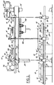
- FIG. 1 is a diagrammatic side view of a workpiece transfer apparatus embodying this invention;
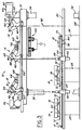
- FIG. 2 is an end view of the workpiece transfer apparatus of FIG. 1;
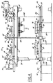
- FIG. 3 is a side view of the workpiece transfer apparatus of FIG. 1 in a second position;
- FIG. 4 is a side view of the workpiece transfer apparatus of FIG. 1 in a third position;
- FIG. 5 is a side view of the workpiece transfer apparatus of FIG. 1 in a fourth position;
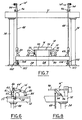
- FIG. 6 is fragmentary side view of a modified lift mechanism;
- FIG. 7 is an end view of a modified workpiece transfer apparatus; and
- FIG. 8 is a fragmentary side view illustrating the lift mechanism of FIG. 7.
-
- Referring in more detail to the drawings, FIGS. 1 - 5 illustrate a
workpiece transfer apparatus 10 having ashuttle 12 actuated bylifting mechanisms 14 disposed above theshuttle 12. Theshuttle 12 is disposed beneathvarious workpieces 16 each received in aseparate workstation 18. To transfer theworkpieces 16 from theircurrent workstations 18 tosubsequent workstations 18, theshuttle 12 is raised by thelifting mechanisms 14 to lift theworkpieces 16 off of their workstations 18 (FIG. 3), and indexingrails 20 of theshuttle 12 are advanced relative to supportrails 22 of theshuttle 12 to dispose theworkpieces 16 over their subsequent workstations 18 (FIG. 4). Theshuffle 12 is then lowered to place theworkpieces 16 in the subsequent workstations 18 (FIG. 5) and the indexingrails 20 are retracted to their starting position so that theapparatus 10 is ready for the next transfer cycle. - Each
workstation 18 has abase 24 received on afloor 28 andlocator pins 30 extending therefrom which are received through holes in theworkpiece 16 to accurately align and locate theworkpiece 16 in theworkstation 18. To properly position theworkpieces 16 in theworkstations 18 on thelocator pins 30, theworkpieces 18 must be raised and lowered generally vertically relative to theworkstations 18 by thelift mechanisms 14. - The
lift mechanisms 14 may be attached to a ceiling or supported on a box frame withtransverse stringers 31 fixed to laterally spaced apartbeams 32 connected touprights 34 extending from thefloor 28. As shown in FIG. 2, parallel sets oflift mechanisms 14 are provided to carry and move opposed sides of theshuttle 12. Eachlifting mechanism 14 preferably has abell crank 40 mounted on apivot 41 fixed to asupport plate 43 connected to thebeam 32. The bell crank has afirst arm 42 pivotally connected to alifting link 44 which is pivotally connected at oneend 46 to one end of a link orrod 48 which at its other is pivotally connected to aplate 49 attached to across rail 50 extending underneath eachsupport rail 22 of theshuttle 12. Asecond arm 52 of eachbell crank 40 is pivotally connected to adrag link 54 which is operably connected to an actuating rod orball screw 55 of adrive mechanism 56 which actuates thelifting mechanisms 14. So that all of thelifting mechanisms 14 may be actuated by asingle drive 56, the twobell cranks 40 of each set are connected together to rotate in unison by a torque tube 57 (FIG. 2) concentric with theirpivots 41 and fixed at its ends to the two bell cranks. Actuating eachlifting mechanism 14 with asingle drive 56 ensures that thelifting mechanisms 14 are driven in unison to provide a stable and controlled movement of theshuttle 12. - The
lift drive 56 may be of substantially any type to advance and retract thedrag link 54, such as a reversible electrical motor, hydraulic cylinder or pneumatic cylinder. If desired, thetorque tubes 57 may be eliminated, and twoseparate drives 56 anddrag links 54 provided, one on each side, to actuate thelift mechanisms 14. In any arrangement, both sets oflink mechanisms 14 are driven in unison to provide an uniform, level and stable movement of theshuttle 12. To improve the stability of theapparatus 10, acounterbalance 60 is connected to thelift mechanisms 14 opposite the lift drive(s) 56. Thecounterbalance 60 is preferably apneumatic cylinder 62 mounted bypivots 61 of asupport 63 on thebeam 32 with anactuating rod 64 pivotally connected to athird arm 65 of the end bell crank 40 of theadjacent lift mechanism 14 to cushion and counterbalance movement of theshuttle 12 and the workpieces. - To provide a true, straight line vertical motion for raising and lowering the
shuffle 12, asecond end 70 of the liftinglink 44, opposite theend 46, is fixed to alinear slide 66 with bearings received on aguide track 68 carried bysupport plate 43. Theslide 66 andguide track 68 cause thesecond end 70 of the liftinglink 44 to move along a straight line path perpendicular to the line of the vertical motion of thefirst end 46 of the liftinglink 44 and intersecting the axis of the fixedpivot 41 of thebell crank 40. Thus, as the lift drive 56 either advances or retracts thedrag link 54 to rotate the bell cranks 40 in unison about theirpivots 41, the liftinglinks 44 provide an essentially straight line vertical motion of therods 48 to raise and lower theshuttle 12 relative to theworkpieces 16. Alternatively, as shown in FIG. 6, lift mechanisms 14' may utilize Scott Russell linkages to provide linear, vertical movement for theshuttle 12. These lift mechanisms 14' have ashort link 82 which at one end is pivotally connected to thesecond end 70 oflift link 44 and at the other end pivotally connected to asupport plate 84 fixed to thebeam 32. As is well known, such a linkage provides an essentially straight line or linear motion of the pivotal connection torods 48. - The
shuttle 12 underlies theworkpieces 16 in theworkstations 18 and has a pair of laterally spaced apart support rails 22 connected to the lifting links 44 through the links orrods 48 and fixed to crossrails 50, and a pair of indexing rails 20 mounted for reciprocation on the support rails 22. When theshuttle 12 is raised, theworkpieces 16 are received on locator andsupport fixtures 72 fixed to the indexing rails 20. - Each
indexing rail 20 hasrollers 73 attached thereto and received in aguide track 74 fixed to its associatedsupport rail 22 to guide the linear reciprocation of theindexing rail 20 relative to thesupport rail 22. Anindexing drive 76 is carried by theshuttle 12 and operably connected to the indexing rails 20 to reciprocate the indexing rails 20 relative to the support rails 22. Theindexing drive 76 preferably comprises a reversible electric motor (not shown) which rotates in unison a pair of drive gears 78 each meshed with aseparate rack 80 fixed to eachindexing rail 20. However, substantially any other type of drive may be used which is capable of reciprocating the indexing rails 20 relative to the support rails 22. - As shown in FIG. 2, the shuttle cross rails 50 are attached at each end to a
linear slide 90 constrained for essentially vertical motion in aguide track 92 to limit the movement of theshuttle 12 to only vertical motion relative to theworkstations 18. Of course, other assemblies may be used to control the movement of theshuttle 12 relative to theworkstations 18. For example, as shown in FIG. 7, the lateral movement of theshuttle 12 may be eliminated by providing afollower 102 with abushing 103 slidably received on aguide pin 104 fixed to thefloor 28 at one end. As shown in FIGS. 7 and 8, with the cross rails 50 and hence, theshuttle 12 so constrained, lifting mechanisms 14'' of substantially any type may be used such as asingle arm 94 pivoted at oneend 96 such that its free end swings on an arc. Desirably, each lifting mechanism 14'' is still interconnected by adrag link 98 to synchronize the lifting mechanisms 14''. In any event, when desired, to accurately place theworkpieces 16 on theworkstations 18, the lifting and lowering of theshuttle 12 can be essentially vertical relative to theworkpieces 16 if desired. Notably, if this essentially vertical movement of theshuttle 12 is not necessary, then greater freedom is provided for theapparatus 10, itslifting mechanisms 14 and itsshuttle 12. - With a
workpiece 16 disposed at eachworkstation 18 and with theshuttle 12 disposed below theworkpieces 18, machining, assembly or other work may be performed on thevarious workpieces 16. For transferring the workpieces the indexing rails 20 are diposed in their retracted position as shown in FIG. 1. To transfer theworkpieces 16 from theircurrent workstations 18 to asubsequent workstation 18, thelift drive 56 is actuated to displace thedrag link 54 and cause rotation of the bell cranks 40 generally counterclockwise about theirpivots 41 as viewed in FIG. 1. This counterclockwise rotation of the bell cranks 40 causes an associated upward movement in unison of the lifting links 44 which are connected to the cross rails 50 to raise theshuttle 12 relative to theworkstations 18 and to lift off and remove theworkpieces 16 from the workstations 18 (FIG. 3). Next, theindexing drive 76 is actuated to advance the indexing rails 20 relative to the support rails 22 to thereby dispose theworkpieces 16 above their respective subsequent workstations 18 (FIG. 4). To place theworkpieces 16 on theirsubsequent workstations 18, thelift drive 56 is reversed to cause a generally clockwise rotation of the bell cranks 40 as viewed in FIG. 1. This causes downward motion of the liftinglinks 44, lowers theshuttle 12 and places theworkpieces 16 on their respective subsequent workstations 18 (FIG. 5). After placing theworkpieces 16 on theworkstations 18, theshuttle 12 is lowered further so that theindexing rail 20 is clear of theworkpieces 18 and then theindexing drive 76 is reversed to retract the indexing rails 20 relative to support rails 22. In this position, thetransfer apparatus 10 is ready to perform another cycle to advance or transferworkpieces 16 to respectivesubsequent workstations 18. - In either embodiment, the lifting
mechanisms 14, 14', 14'' are disposed above theshuttle 12 which is disposed beneath theworkpieces 16. Because there are no clamping devices and theshuttle 12 is not disposed above the workstations as in a conventional overhead lift and carry device, a repair hoist 100 may be used above theworkpieces 16. Desirably, with thelift drive 56 andlifting mechanisms 14, 14', 14'' out of the way of theworkstations 18, fixtures and/or tools therein can be interchanged, or replaced when theshuttle 12 is raised and theworkpieces 16 are removed from the workstations. This greatly increases the flexibility of theapparatus 10 which may be used withdifferent workpieces 16 by simply changing the fixtures, tooling, locators and/or workstations. Further, with thelift drive 56 andlifting mechanisms 14, 14', 14'' above theworkstations 18, they are removed from the contaminants, coolants, chips, etc., which fall from theworkstations 18 and which would otherwise foul the mechanisms. Still further, theshuttle 12 engages theworkpieces 16 from underneath to reduce the complexity of the work cycle and to increase the safety in use of theapparatus 10. Still further, with the relativelythin links 48 extending betweenworkstations 18, theworkstations 18 can be closely grouped together to increase the number ofworkstations 18 disposed in a given floor space.
Claims (12)
- A workpiece transfer device, comprising:a shuttle having a support rail and an indexing rail carried by the support rail and movable relative to the support rail between a retracted position and an advanced position, the shuffle being constructed to be disposed beneath at least one workpiece and being movable between a lowered position spaced from the workpiece and a raised position engaged with the workpiece and lifting the workpiece from a workstation;at least one lift mechanism disposed above the shuffle and the workpiece, operably connected to the shuffle and movable between a first position and a second position to move the shuffle between its raised and lowered positions;a first drive mechanism operably connected to the lift mechanism to move the lift mechanism between its first and second positions; anda second drive mechanism operably connected to the indexing rail to move the indexing rail between its retracted and advanced positions whereby, to transfer a workpiece from a first workstation to a subsequent workstation, the lift mechanism is actuated to move the shuffle from its lowered position to its raised position to lift the workpiece from said first workstation, the second drive mechanism is actuated to move the indexing rail from its retracted position to its advanced position to move the workpiece over said subsequent workstation, and the shuffle is moved to its lowered position to deposit the workpiece in said subsequent workstation.
- The device of claim 1 wherein each lift mechanism is constructed to move the shuttle vertically in an essentially straight line between its raised and lowered positions.
- The device of claim 2 wherein each lift mechanism is a Scott Russell linkage.
- The device of claim 1 wherein the second drive mechanism comprises a rack and pinion gear set.
- The device of claim 1 which also comprises a guide to which the shuttle is connected to control the path of travel of the shuttle as it is moved between its lowered and raised positions.
- The device of claim 5 wherein the guide comprises a track and follower received on the track and one of the track and follower is connected to the shuttle.
- The device of claim 1 wherein the lift mechanism has a bell crank mounted for rotation about a pivot and having a first arm operably connected to the first drive mechanism and a second arm, a lift link connected to the second arm between the first and second ends of the lift link, operably connected at a first end to the shuffle and at a second end to a slide assembly to permit sliding movement of the second end of the lift link relative to the pivot of the bell crank so tat the lift mechanism causes an essentially straight line movement of the shuffle when driven by the first drive mechanism.
- The device of claim 7 which also comprises at least one additional lift mechanism and a drag link operably connecting each lift mechanism to each other and the first drive mechanism.
- The device of claim 7 wherein the drag link is connected to the first arm of each bell crank.
- The device of claim 5 wherein each lift mechanism is an arm pivoted at one end and operably connected to the first drive mechanism for pivotal movement about said one end.
- The device of claim 5 wherein the guide comprises a follower with an opening therethrough and a pin slidably received in the opening and one of the pin and the follower is connected to the shuttle.
- The device of claim 1 wherein the shuffle also has at least one cross rail extending generally perpendicular to and underlying the support rail with each lift mechanism operably connected to a cross rail.
Applications Claiming Priority (4)
| Application Number | Priority Date | Filing Date | Title |
|---|---|---|---|
| US384612 | 1989-07-25 | ||
| US13077699P | 1999-04-23 | 1999-04-23 | |
| US130776P | 1999-04-23 | ||
| US09/384,612 US6298979B1 (en) | 1999-04-23 | 1999-08-27 | Workpiece transfer apparatus with overhead actuator |
Publications (2)
| Publication Number | Publication Date |
|---|---|
| EP1048398A2 true EP1048398A2 (en) | 2000-11-02 |
| EP1048398A3 EP1048398A3 (en) | 2001-12-05 |
Family
ID=26828801
Family Applications (1)
| Application Number | Title | Priority Date | Filing Date |
|---|---|---|---|
| EP00108233A Withdrawn EP1048398A3 (en) | 1999-04-23 | 2000-04-14 | Workpiece transfer apparatus with overhead actuator |
Country Status (4)
| Country | Link |
|---|---|
| US (1) | US6298979B1 (en) |
| EP (1) | EP1048398A3 (en) |
| CA (1) | CA2305937A1 (en) |
| MX (1) | MXPA00003814A (en) |
Cited By (2)
| Publication number | Priority date | Publication date | Assignee | Title |
|---|---|---|---|---|
| CN105712039A (en) * | 2014-12-22 | 2016-06-29 | 哈耶工程与发展公司 | Pallet Conveyance System And Method |
| ITMI20150577A1 (en) * | 2015-04-22 | 2016-10-22 | Elti Srl | EQUIPMENT FOR THE CONTROLLED HANDLING, ALONG A DIRECTION OF HANDLING, OF PRODUCTS IN CONTINUOUS SYSTEMS, ESPECIALLY FOR HEATING OVENS OR HEAT TREATMENT OF METAL PRODUCTS. |
Families Citing this family (5)
| Publication number | Priority date | Publication date | Assignee | Title |
|---|---|---|---|---|
| FR2906265B1 (en) * | 2006-09-22 | 2008-12-19 | Frederic Vacheron | INSTALLATION FOR PROCESSING THE SURFACE OF PIECES BY IMMERSION IN A TREATMENT FLUID. |
| JP5083278B2 (en) * | 2009-06-15 | 2012-11-28 | 村田機械株式会社 | Automatic warehouse in front of equipment |
| CN103132103B (en) * | 2011-12-02 | 2016-12-21 | 洛阳宇航重工科技股份有限公司 | A kind of propulsion plant for removing aluminium oxide crusting block on double anode unit system |
| JP5855962B2 (en) * | 2012-02-06 | 2016-02-09 | 徳田工業株式会社 | Processing system |
| CN111792304A (en) * | 2020-07-14 | 2020-10-20 | 惠州英特智能设备有限公司 | Linear type slider lifting circulation line |
Citations (4)
| Publication number | Priority date | Publication date | Assignee | Title |
|---|---|---|---|---|
| US2856079A (en) * | 1958-10-14 | Article handler | ||
| US4377986A (en) * | 1980-06-20 | 1983-03-29 | Juve Robert J | Hoist plating line |
| US5127787A (en) * | 1990-05-24 | 1992-07-07 | Brothers Industries, Inc. | Lift and carry mechanism and method |
| US5636962A (en) * | 1993-09-20 | 1997-06-10 | Toyoda Koki Kabushiki Kaisha | Automatic transfer apparatus |
Family Cites Families (9)
| Publication number | Priority date | Publication date | Assignee | Title |
|---|---|---|---|---|
| US2033848A (en) * | 1934-07-17 | 1936-03-10 | Fruit Packers Supply And Equip | Fruit and vegetable washing machine |
| US2088284A (en) * | 1935-11-01 | 1937-07-27 | Mij Exploitatie Octrooien Nv | Device for conveying articles in continuous furnaces |
| US2930333A (en) * | 1955-10-21 | 1960-03-29 | Konink Verkade Fabricken N V | Oven for baking, heating or keeping bakers' wares at a constant temperature |
| US3016004A (en) * | 1960-01-26 | 1962-01-09 | Hygrade Food Products Corp | Meat treating |
| US4865180A (en) * | 1985-08-07 | 1989-09-12 | Lamb Technicon Corp. | Workpiece transfer system |
| USRE32804E (en) * | 1985-08-09 | 1988-12-20 | Lamb Technicon Corp. | Workpiece transfer |
| US4669607A (en) * | 1985-08-09 | 1987-06-02 | Lamb Technicon Corp. | Workpiece transfer |
| US4781285A (en) * | 1987-09-21 | 1988-11-01 | Progressive Tool & Industries Company | Soft touch drive for article handling apparatus |
| WO1994016840A1 (en) * | 1993-01-21 | 1994-08-04 | Kabushiki Kaisha Komatsu Seisakusho | Transfer feeder |
-
1999
- 1999-08-27 US US09/384,612 patent/US6298979B1/en not_active Expired - Fee Related
-
2000
- 2000-04-14 EP EP00108233A patent/EP1048398A3/en not_active Withdrawn
- 2000-04-18 MX MXPA00003814A patent/MXPA00003814A/en unknown
- 2000-04-18 CA CA002305937A patent/CA2305937A1/en not_active Abandoned
Patent Citations (4)
| Publication number | Priority date | Publication date | Assignee | Title |
|---|---|---|---|---|
| US2856079A (en) * | 1958-10-14 | Article handler | ||
| US4377986A (en) * | 1980-06-20 | 1983-03-29 | Juve Robert J | Hoist plating line |
| US5127787A (en) * | 1990-05-24 | 1992-07-07 | Brothers Industries, Inc. | Lift and carry mechanism and method |
| US5636962A (en) * | 1993-09-20 | 1997-06-10 | Toyoda Koki Kabushiki Kaisha | Automatic transfer apparatus |
Cited By (2)
| Publication number | Priority date | Publication date | Assignee | Title |
|---|---|---|---|---|
| CN105712039A (en) * | 2014-12-22 | 2016-06-29 | 哈耶工程与发展公司 | Pallet Conveyance System And Method |
| ITMI20150577A1 (en) * | 2015-04-22 | 2016-10-22 | Elti Srl | EQUIPMENT FOR THE CONTROLLED HANDLING, ALONG A DIRECTION OF HANDLING, OF PRODUCTS IN CONTINUOUS SYSTEMS, ESPECIALLY FOR HEATING OVENS OR HEAT TREATMENT OF METAL PRODUCTS. |
Also Published As
| Publication number | Publication date |
|---|---|
| CA2305937A1 (en) | 2000-10-23 |
| EP1048398A3 (en) | 2001-12-05 |
| MXPA00003814A (en) | 2002-03-08 |
| US6298979B1 (en) | 2001-10-09 |
Similar Documents
| Publication | Publication Date | Title |
|---|---|---|
| US4573862A (en) | Workpiece transfer device | |
| US4669607A (en) | Workpiece transfer | |
| CA1273314A (en) | Workpiece transfer system | |
| US6298979B1 (en) | Workpiece transfer apparatus with overhead actuator | |
| CN108818513B (en) | Rotary feeding manipulator | |
| USRE32804E (en) | Workpiece transfer | |
| CN111468940A (en) | Automatic pressure equipment machine of reservoir | |
| CN117352449B (en) | Automatic assembly device for IGBT module outer frames | |
| US4973443A (en) | System for removing and installing a control rod drive | |
| CN209936318U (en) | Automatic pressure equipment machine of reservoir | |
| KR100594045B1 (en) | Device conveying drive and method of transfer press | |
| CN110000482B (en) | Position-exchangeable double-workbench structure for laser cutting machine | |
| CN109256347B (en) | Intelligent production line for manufacturing chips | |
| US5878641A (en) | Cutting apparatus | |
| CN113070719B (en) | Full autoloading work piece processingequipment | |
| JP2708918B2 (en) | System for transferring workpieces through a series of processing stations | |
| US5019325A (en) | Method for removing and installing a control rod drive | |
| CN112059521A (en) | Displacement system for automatic welding production line of light steel structure | |
| CN207712953U (en) | A kind of sprocket wheel actuator servo translation grasping mechanism | |
| GB1489627A (en) | Rake type cooling bed for round and polygonal sections | |
| CN110340715A (en) | A kind of feeding device of product production line | |
| CN2718484Y (en) | Transporting device for car tunnel furnace | |
| CN212449655U (en) | Panel loading attachment for lathe | |
| CN214024388U (en) | Carrier replacing mechanism based on manipulator | |
| CN217413154U (en) | Machine tool |
Legal Events
| Date | Code | Title | Description |
|---|---|---|---|
| PUAI | Public reference made under article 153(3) epc to a published international application that has entered the european phase |
Free format text: ORIGINAL CODE: 0009012 |
|
| AK | Designated contracting states |
Kind code of ref document: A2 Designated state(s): DE ES FR GB SE Kind code of ref document: A2 Designated state(s): AT BE CH CY DE DK ES FI FR GB GR IE IT LI LU MC NL PT SE |
|
| AX | Request for extension of the european patent |
Free format text: AL;LT;LV;MK;RO;SI |
|
| PUAL | Search report despatched |
Free format text: ORIGINAL CODE: 0009013 |
|
| AK | Designated contracting states |
Kind code of ref document: A3 Designated state(s): AT BE CH CY DE DK ES FI FR GB GR IE IT LI LU MC NL PT SE |
|
| AX | Request for extension of the european patent |
Free format text: AL;LT;LV;MK;RO;SI |
|
| RIC1 | Information provided on ipc code assigned before grant |
Free format text: 7B 23Q 7/14 A, 7B 65G 25/02 B |
|
| 17P | Request for examination filed |
Effective date: 20020314 |
|
| AKX | Designation fees paid |
Free format text: DE ES FR GB SE |
|
| GRAP | Despatch of communication of intention to grant a patent |
Free format text: ORIGINAL CODE: EPIDOSNIGR1 |
|
| STAA | Information on the status of an ep patent application or granted ep patent |
Free format text: STATUS: THE APPLICATION IS DEEMED TO BE WITHDRAWN |
|
| 18D | Application deemed to be withdrawn |
Effective date: 20040109 |