EP1048360B1 - Vorrichtung und Verfahren zum Einbringen eines festen Ausgangsmaterials eines Reduktionsmittels eines Stickoxids in ein Abgas - Google Patents
Vorrichtung und Verfahren zum Einbringen eines festen Ausgangsmaterials eines Reduktionsmittels eines Stickoxids in ein Abgas Download PDFInfo
- Publication number
- EP1048360B1 EP1048360B1 EP00109285A EP00109285A EP1048360B1 EP 1048360 B1 EP1048360 B1 EP 1048360B1 EP 00109285 A EP00109285 A EP 00109285A EP 00109285 A EP00109285 A EP 00109285A EP 1048360 B1 EP1048360 B1 EP 1048360B1
- Authority
- EP
- European Patent Office
- Prior art keywords
- exhaust gas
- source material
- starting material
- disc
- reducing agent
- Prior art date
- Legal status (The legal status is an assumption and is not a legal conclusion. Google has not performed a legal analysis and makes no representation as to the accuracy of the status listed.)
- Expired - Lifetime
Links
Images


Classifications
-
- B—PERFORMING OPERATIONS; TRANSPORTING
- B05—SPRAYING OR ATOMISING IN GENERAL; APPLYING FLUENT MATERIALS TO SURFACES, IN GENERAL
- B05B—SPRAYING APPARATUS; ATOMISING APPARATUS; NOZZLES
- B05B7/00—Spraying apparatus for discharge of liquids or other fluent materials from two or more sources, e.g. of liquid and air, of powder and gas
- B05B7/14—Spraying apparatus for discharge of liquids or other fluent materials from two or more sources, e.g. of liquid and air, of powder and gas designed for spraying particulate materials
- B05B7/1404—Arrangements for supplying particulate material
-
- B—PERFORMING OPERATIONS; TRANSPORTING
- B01—PHYSICAL OR CHEMICAL PROCESSES OR APPARATUS IN GENERAL
- B01D—SEPARATION
- B01D53/00—Separation of gases or vapours; Recovering vapours of volatile solvents from gases; Chemical or biological purification of waste gases, e.g. engine exhaust gases, smoke, fumes, flue gases, aerosols
- B01D53/34—Chemical or biological purification of waste gases
- B01D53/74—General processes for purification of waste gases; Apparatus or devices specially adapted therefor
- B01D53/77—Liquid phase processes
- B01D53/79—Injecting reactants
-
- B—PERFORMING OPERATIONS; TRANSPORTING
- B01—PHYSICAL OR CHEMICAL PROCESSES OR APPARATUS IN GENERAL
- B01D—SEPARATION
- B01D53/00—Separation of gases or vapours; Recovering vapours of volatile solvents from gases; Chemical or biological purification of waste gases, e.g. engine exhaust gases, smoke, fumes, flue gases, aerosols
- B01D53/34—Chemical or biological purification of waste gases
- B01D53/74—General processes for purification of waste gases; Apparatus or devices specially adapted therefor
- B01D53/86—Catalytic processes
- B01D53/90—Injecting reactants
-
- B—PERFORMING OPERATIONS; TRANSPORTING
- B01—PHYSICAL OR CHEMICAL PROCESSES OR APPARATUS IN GENERAL
- B01D—SEPARATION
- B01D53/00—Separation of gases or vapours; Recovering vapours of volatile solvents from gases; Chemical or biological purification of waste gases, e.g. engine exhaust gases, smoke, fumes, flue gases, aerosols
- B01D53/34—Chemical or biological purification of waste gases
- B01D53/92—Chemical or biological purification of waste gases of engine exhaust gases
- B01D53/94—Chemical or biological purification of waste gases of engine exhaust gases by catalytic processes
- B01D53/9404—Removing only nitrogen compounds
- B01D53/9409—Nitrogen oxides
- B01D53/9431—Processes characterised by a specific device
-
- F—MECHANICAL ENGINEERING; LIGHTING; HEATING; WEAPONS; BLASTING
- F01—MACHINES OR ENGINES IN GENERAL; ENGINE PLANTS IN GENERAL; STEAM ENGINES
- F01N—GAS-FLOW SILENCERS OR EXHAUST APPARATUS FOR MACHINES OR ENGINES IN GENERAL; GAS-FLOW SILENCERS OR EXHAUST APPARATUS FOR INTERNAL-COMBUSTION ENGINES
- F01N3/00—Exhaust or silencing apparatus having means for purifying, rendering innocuous, or otherwise treating exhaust
- F01N3/08—Exhaust or silencing apparatus having means for purifying, rendering innocuous, or otherwise treating exhaust for rendering innocuous
- F01N3/10—Exhaust or silencing apparatus having means for purifying, rendering innocuous, or otherwise treating exhaust for rendering innocuous by thermal or catalytic conversion of noxious components of exhaust
- F01N3/18—Exhaust or silencing apparatus having means for purifying, rendering innocuous, or otherwise treating exhaust for rendering innocuous by thermal or catalytic conversion of noxious components of exhaust characterised by methods of operation; Control
- F01N3/20—Exhaust or silencing apparatus having means for purifying, rendering innocuous, or otherwise treating exhaust for rendering innocuous by thermal or catalytic conversion of noxious components of exhaust characterised by methods of operation; Control specially adapted for catalytic conversion
- F01N3/206—Adding periodically or continuously substances to exhaust gases for promoting purification, e.g. catalytic material in liquid form, NOx reducing agents
- F01N3/2066—Selective catalytic reduction [SCR]
-
- F—MECHANICAL ENGINEERING; LIGHTING; HEATING; WEAPONS; BLASTING
- F01—MACHINES OR ENGINES IN GENERAL; ENGINE PLANTS IN GENERAL; STEAM ENGINES
- F01N—GAS-FLOW SILENCERS OR EXHAUST APPARATUS FOR MACHINES OR ENGINES IN GENERAL; GAS-FLOW SILENCERS OR EXHAUST APPARATUS FOR INTERNAL-COMBUSTION ENGINES
- F01N2610/00—Adding substances to exhaust gases
- F01N2610/02—Adding substances to exhaust gases the substance being ammonia or urea
-
- Y—GENERAL TAGGING OF NEW TECHNOLOGICAL DEVELOPMENTS; GENERAL TAGGING OF CROSS-SECTIONAL TECHNOLOGIES SPANNING OVER SEVERAL SECTIONS OF THE IPC; TECHNICAL SUBJECTS COVERED BY FORMER USPC CROSS-REFERENCE ART COLLECTIONS [XRACs] AND DIGESTS
- Y02—TECHNOLOGIES OR APPLICATIONS FOR MITIGATION OR ADAPTATION AGAINST CLIMATE CHANGE
- Y02T—CLIMATE CHANGE MITIGATION TECHNOLOGIES RELATED TO TRANSPORTATION
- Y02T10/00—Road transport of goods or passengers
- Y02T10/10—Internal combustion engine [ICE] based vehicles
- Y02T10/12—Improving ICE efficiencies
Definitions
- the invention relates to a device for introducing a solid starting material of a reducing agent of a nitrogen oxide into an exhaust gas through a metering opening. Such a device goes out EP 0 615 777 A1 out. In addition to the device, a method for introducing a gaseous reducing agent into an exhaust gas is specified.
- nitrogen oxide is produced as an unwanted by-product.
- an environmental compatibility of the combustion it is desirable to prevent formation of this nitrogen oxide or to subsequently remove the nitrogen oxide from an exhaust gas of the combustion.
- the subsequent removal of the nitrogen oxide is done, for example, in that the exhaust gas is added to a reducing agent for the nitrogen oxide.
- powdery urea is metered into the exhaust gas with the aid of a precision metering device.
- a transportable solid air mixture (aerosol) is first formed by means of a compressed air and a spray nozzle. This aerosol is supplied to the exhaust gas.
- ammonia is formed from the urea in a hydrolysis.
- the ammonia formed acts as a reducing agent of the nitrogen oxide.
- nitrogen oxide is reacted with ammonia to form molecular nitrogen and carbon dioxide.
- the object of the present invention is to provide a device with the aid of which a solid starting material of a reducing agent of nitrogen oxides can be defined and fed to an exhaust gas in a simple manner.
- a device for introducing a solid starting material of a reducing agent of a nitrogen oxide in an exhaust pipe flowing in an exhaust gas is indicated by at least one metering, characterized in that the device comprises means for varying a diameter of the metering.
- the exhaust gas is for example the exhaust gas of an internal combustion engine, in particular a diesel or gasoline engine.
- the exhaust gas may also be the exhaust gas of a fossil-fueled power plant.
- a fossil fuel e.g., natural gas
- a non-fossil fuel e.g., hydrogen
- the reducing agent is in particular gaseous.
- the reducing agent is ammonia, which reduces nitrogen oxides to molecular nitrogen with the aid of a catalyst.
- the starting material of ammonia is, for example, urea.
- the starting material of the reducing agent passes into the exhaust gas. This is for example realized so that a reservoir with a supply of the starting material and an exhaust pipe with the exhaust gas are arranged together so that the starting material trickles due to gravity through the metering in the exhaust pipe. It is also conceivable that the starting material in the Exhaust pipe is blown or sucked. At a temperature of the exhaust pipe from 350 ° C to 600 ° C takes place in the exhaust pipe, a reaction of urea in ammonia.
- the reservoir may be fixed or separable connected to the exhaust pipe.
- the reservoir is welded to the exhaust pipe, screwed or plugged.
- the reservoir may also be connected indirectly via a hollow body in the form of a connecting piece to the exhaust pipe.
- the starting material passes from the reservoir through the fitting into the exhaust of the exhaust pipe.
- the basic idea of the invention is to offer a metering opening for introducing the starting material, which has a variable diameter. By changing the diameter of the metering orifice, it is possible to determine an amount of the starting material which is introduced into the exhaust gas.
- the device preferably has a multiplicity of such metering openings.
- the shape of a metering is free, it can be oval, round or take any other conceivable shape.
- the diameters of the metering orifices are particularly dimensioned so that a particle of the starting material enters the exhaust gas, which is completely decomposed in the exhaust gas.
- a particle has a particle size of a few microns.
- larger diameter particles have the advantage of having a small surface area compared to the volume.
- the metering orifice with variable diameter or the means for changing the diameter can be integrated in the reservoir, the connecting piece or in a wall of the exhaust pipe.
- a material of the diameter altering agent is preferably inert to the starting material. It is also advantageous if the material is inert to the reducing agent formed and to a reaction product of the reduction.
- the means for changing the diameter of the metering orifice for example, a diaphragm with an adjustable aperture.
- the means for changing the diameter of the metering opening to a first body having at least a first hole and at least a second body having at least one second hole.
- the first body and the second body are juxtaposed so that the metering orifice is formed by the first and second holes.
- a hole penetrates the body in one direction, so that a pinhole is realized.
- a body is preferably a plate.
- a hole penetrates the plate in the thickness direction.
- a first and a second plate are arranged with their major surfaces parallel to each other so that the starting material trickles through the first holes of the first plate and through the second holes of the second plate.
- the first holes and the second holes may have a same shape. But they can also be shaped differently.
- the first holes of the first plate are circular and the second holes of the second plate are annular.
- the plates are each arranged with a major surface form-fitting manner to each other or at a distance from each other. For example, the distance is smaller than a particle size of the starting material. This prevents starting material from accumulating between the plates.
- the diameter of the metering openings are fixed. Changing the diameter of the metering opening is possible, for example, in that the bodies are mounted so as to be movable relative to one another or displaceable.
- a plate is a disc with a pivot point.
- the pivot point is, for example, the center of the disc.
- the disc is rotatably mounted about the pivot point. It can be stored only one disc so, but it can also be stored several discs in this way. By moving the disks around their respective fulcrum, a diameter of a metering orifice is adjusted and thus an amount of starting material is determined, which is introduced into the exhaust gas.
- At least one body is arranged on a supply of the starting material.
- the supply of starting material is for example in a storage container.
- a body having a side having the holes is in direct contact with the supply of the starting material.
- a means for crushing the starting material is present.
- the starting material is introduced in a particle size of a few microns.
- the holes of the bodies are dimensioned accordingly. So that the starting material can pass through the holes or the metering opening, it has a particle size which is smaller than a diameter of the metering opening. This ensures the means for crushing the starting material.
- the means for comminuting the starting material is, for example, a grinder which is mounted directly in the storage container or between the storage container and the metering opening.
- the means for comminuting is at least one prong which projects into the supply of the starting material.
- the starting material is crushed or solid starting material scraped off by a compressed example of starting material.
- a shape of the point is arbitrary.
- the tine is for example pen-shaped.
- the tine is preferably arranged at a hole, in particular at a hole of the body, which is in contact with the supply of starting material.
- a hole at one hole, several prongs can be arranged.
- a body having a plurality of holes and prongs is a grater.
- the grater has, for example, the form of a nutmeg grater or the shape of a potato grater.
- To ensure a flowability of the starting material of the reservoir for the starting material may be equipped with a desiccant.
- a means for controlling the stock of the starting material is present.
- these products are used to test a quality of the starting material.
- a water content of the starting material is as low as possible in order to ensure the flowability of the starting material.
- a determination of the water content is achieved, for example, by means of an absorption or reflection measurement.
- the supply of the starting material is irradiated with infrared light, which is absorbed by water. Due to the measured absorption can be concluded on the water content of the stock. If the water content is too large, the supply of starting material may be clumped. In this case, replacement of the stock may be advantageous.
- This agent is for example a light barrier attached to the reservoir. As soon as the supply in the storage container under a set by the light barrier Level decreases, it is indicated that the existing supply of starting material is coming to an end. It must be refilled starting material. If the reservoir is removably attached, for example, an exchange of an empty reservoir against a filled reservoir can be made. Multiple light barriers make it possible to track a progressive consumption of starting material.
- a method for introducing at least one solid starting material of at least one reducing agent of a nitrogen oxide into an exhaust gas through at least one metering opening with a variable diameter.
- the method comprises the steps of determining an amount of starting material required for reduction of the nitrogen oxide and varying the diameter of the metering orifice in accordance with the required amount of starting material.
- Determining the required amount of the starting material includes, in particular, measuring a content of nitrogen oxide in the exhaust gas or gas mixture. This succeeds, for example, with a nitrogen oxide sensor.
- the nitrogen oxide sensor measures, for example, the amount of nitrogen oxides that are still present after leaving the catalyst for the conversion of nitrogen oxides into nitrogen carbon dioxide.
- the nitrogen oxide sensor can also be used to measure the content of nitrogen oxides in the exhaust gas before the catalyst. According to a signal of the nitrogen oxide sensor, the amount of starting material is determined, which is to be introduced into the gas mixture.
- a first hole of a first body and at least a second hole of at least one second body form the metering opening with a variable diameter. Changing the diameter is done by moving at least one of the bodies. For example, a body in the form of a plate in a certain direction relative to a second plate in one direction.
- a disk is used as the body.
- the body is moved by rotating the disc about a pivot point of the disc.
- the pivot point of the disc is located in the center of the disc.
- the diameter of the metering opening is changed.
- the rotation of the disc takes place at a constant speed.
- the disk is brought into contact with the supply of starting material. If the disc is designed with teeth and protrude the spikes in the supply of starting material, it is automatically carried out by turning the disc, a crushing or ablation of the starting material.
- the comminuted starting material trickles, for example, through the first holes of the first disc and passes through the second holes of the second disc in the exhaust gas.
- At least one movably mounted body can be activated and thus a positioning of the holes of the body relative to the holes of another body can be determined. This is achieved, for example, with a stepper motor controller.
- the reducing agent used is in particular a reducing agent having at least one nitrogen atom, such as ammonia. It may also be an aliphatic ammonia derivative.
- urea is used as the starting material. With urea combines the advantage that urea is reacted at a temperature between 350 ° C and 600 ° C to ammonia and carbon dioxide. These temperatures prevail, for example, in the exhaust pipe of a passenger car.
- ammonia such as ammonium carbonate, ammonium carbamate, Amonniumhydrogencarbonat, ammonium formate, ammonium oxalate, ammonium hydroxide, cyanuric acid, urea-formaldehyde, melamine and mixtures of these compounds are also conceivable.
- Cyanuric acid can be converted, for example, at the temperatures of the exhaust gas to cyanic acid, which can also act as a reducing agent of nitrogen oxides.
- the starting point is an exhaust gas 1 of a diesel engine 15.
- the exhaust gas 1 is moved through an exhaust pipe 2 in the flow direction 3 ( FIG. 5 ).
- nitrogen oxides are contained due to the combustion in the presence of molecular nitrogen. These nitrogen oxides are removed with the aid of a catalyst 4 and ammonia as a reducing agent from the exhaust gas 1.
- a supply 51 of the urea 5 is located in a reservoir 6, which is connected via a connecting piece 7 to the exhaust pipe 2.
- the reservoir 6 is screwed to the connector 7, which in turn is welded to the exhaust pipe 2.
- the connecting piece 7 is a hollow body through which the urea 5 passes into the exhaust gas 1 of the exhaust pipe 2.
- Connecting piece 7, reservoir 6 and exhaust pipe 2 are arranged so that the urea 5 passes into the exhaust pipe 2 due to gravity.
- the means 8 consists of two discs 81 and 82 with round holes 811 and 821 (pinhole, FIG. 1 ).
- a hole has a hole diameter of about 50 microns.
- the discs 81 and 82 are arranged one above the other so that the first holes 811 of the first disc 81 and the second holes 821 of the second disc 82 form the openings 10 with variable diameters 9.
- a first disc 81 is in direct contact with the supply 51 of urea 5. This disc 81 is rotatably mounted about a pivot point 812 in the middle of the disc 81 ( FIG. 4 ).
- the disc 81 By turning the first disc 81, the diameters 9 of the openings 10 change.
- the disc 81 has teeth 813 which are arranged directly on the holes 811 of the disc 81 ( FIG. 3 ). The serrations 813 crush when spinning 103 of the disc 81 existing larger particles of urea 5, which would not fit through the metering orifices 10.
- a desiccant 11 is present in the reservoir 6, a desiccant 11 is present.
- the desiccant 11 ensures that a water content of the urea 5 is so low that the urea 5 is free-flowing.
- the desiccant 11 has silica gel.
- a gas sensor 12 for nitrogen oxides is arranged after the catalyst 4 (FIG. 5).
- the starting point is a start of the diesel engine 15. With the start of a measurement 101 of nitrogen oxide in the exhaust gas 1 is set in motion. With the aid of the gas sensor 12, a content of nitrogen oxides in the exhaust gas 1 is examined. In step 102, the amount of urea 5 to be introduced into the exhaust gas 1 is determined according to the content. In step 103, the first disc 81 is rotated relative to the second disc 81 and thus the diameter 9 of the metering orifices 10 is changed. If the content of nitrogen oxides is too high, the diameter 9 is increased and the metering opening 10 is increased.
- a further gas sensor 13 is provided after the catalyst 4, which determines a content of ammonia in the exhaust gas 1. This content is also used to control the amount of urea 5, which is introduced into the exhaust gas 1.
- the second disc 82 is rotatably mounted about a pivot point in the center of the second disc 82.
- Another embodiment differs in the shape of the holes 811 and 821 of the discs 81 and 82.
- the holes of the first and second discs are quasi-complementary designed.
- the first holes 811 of the first disc 81 are circular holes 814.
- the second holes 821 of the second disc 82 are formed as segmented rings 815.
- a further embodiment also has a means 14 for controlling a reservoir 51 of urea 5.
- This means is a light barrier consisting of a light-emitting photodiode and a light-registering photodetector.
- the light barrier 14 is arranged on the reservoir 6. Between photodiode and photodetector is the supply 51 of urea. As soon as the reservoir 51 of urea 5 drops below a certain level, a signal is generated which indicates to the operator that a certain amount of urea 5 present has fallen below. In the following urea 5 is refilled into the reservoir 6. After the reservoir is screwed to the connector, the empty reservoir 6 is exchanged for a new, filled with urea 5 reservoir 6 in another embodiment.
Landscapes
- Engineering & Computer Science (AREA)
- Chemical & Material Sciences (AREA)
- Chemical Kinetics & Catalysis (AREA)
- Environmental & Geological Engineering (AREA)
- Health & Medical Sciences (AREA)
- Analytical Chemistry (AREA)
- General Chemical & Material Sciences (AREA)
- Oil, Petroleum & Natural Gas (AREA)
- Biomedical Technology (AREA)
- Combustion & Propulsion (AREA)
- Toxicology (AREA)
- Mechanical Engineering (AREA)
- General Engineering & Computer Science (AREA)
- Exhaust Gas After Treatment (AREA)
- Treating Waste Gases (AREA)
- Exhaust Gas Treatment By Means Of Catalyst (AREA)
Description
- Die Erfindung betrifft eine Vorrichtung zum Einbringen eines festen Ausgangsmaterials eines Reduktionsmittels eines Stickoxids in ein Abgas durch eine Dosieröffnung. Eine derartige Vorrichtung geht aus
EP 0 615 777 A1 hervor. Neben der Vorrichtung wird ein Verfahren zum Einbringen eines gasförmigen Reduktionsmittels in ein Abgas angegeben. - Bei einer Verbrennung eines fossilen Energieträgers in Anwesenheit von Luft entsteht als ein unerwünschtes Nebenprodukt Stickoxid. Im Hinblick auf eine Umweltverträglichkeit der Verbrennung ist es wünschenswert, eine Bildung dieses Stickoxids zu unterbinden bzw. das Stickoxid nachträglich aus einem Abgas der Verbrennung zu entfernen. Die nachträgliche Entfernung des Stickoxids geschieht beispielsweise dadurch, daß dem Abgas ein Reduktionsmittel für das Stickoxid beigemengt wird. Ein derartiges Verfahren und eine entsprechende Vorrichtung gehen beispielsweise aus
EP 0 615 777 A1 hervor. Dabei wird pulverförmiger Harnstoff mit Hilfe eines Präzisionsdosiergerätes in das Abgas eindosiert. In einem relativ komplizierten Verfahren wird mit Hilfe einer Preßluft und einer Zerstäuberdüse zunächst ein transportfähiges Feststoffluftgemisch (Aerosol) gebildet. Dieses Aerosol wird dem Abgas zugeführt. Auf einer Oberfläche eines Hydrolysekatalysators für Harnstoff wird (in Gegenwart von Wasser des Abgases) aus dem Harnstoff in einer Hydrolyse Ammoniak gebildet. Das gebildete Ammoniak fungiert als Reduktionsmittel des Stickoxids. Mit Hilfe eines zweiten Katalysators wird Stickoxid mit Ammoniak zu molekularem Stickstoff und Kohlendioxid umgesetzt. - Aus der
DE 44 23 003 A1 sind ein Verfahren und eine Vorrichtung zum Reduzieren von NOx in den Abgasen bei der Verbrennung in einem Kraftfahrzeug-Motor zu entnehmen. Dabei wird ein pulverartiges reduzierendes Agen über einen trichterförmigen Verteiler und ein rotierendes Verteilerrad in die Motorgase zugegeben. - Aufgabe der vorliegenden Erfindung ist es, eine Vorrichtung anzugeben, mit deren Hilfe ein festes Ausgangsmaterial eines Reduktionsmittels von Stickoxiden definiert und auf einfache Weise einem Abgas zugeführt werden kann.
- Zur Lösung der Aufgabe wird eine Vorrichtung zum Einbringen eines festen Ausgangsmaterials eines Reduktionsmittels eines Stickoxids in ein in einem Auspuffrohr strömendes Abgas durch mindestens eine Dosieröffnung angegeben, dadurch gekennzeichnet, daß die Vorrichtung ein Mittel zu einem Verändern eines Durchmessers der Dosieröffnung aufweist.
- Das Abgas ist beispielsweise das Abgas einer Verbrennungsmaschine, insbesondere eines Diesel- oder Ottomotors. Das Abgas kann auch das Abgas eines fossil befeuerten Kraftwerks sein. Bei der Verbrennung kann sowohl ein fossiler Energieträger (z.B. Erdgas) als auch ein nicht-fossiler Energieträger (z.B. Wasserstoff) oxidiert werden.
- Das Reduktionsmittel ist insbesondere gasförmig. Beispielsweise ist das Reduktionsmittel Ammoniak, das Stickoxide mit Hilfe eines Katalysators zu molekularem Stickstoff reduziert. Das Ausgangsmaterial von Ammoniak ist beispielsweise Harnstoff. Durch die Dosieröffnung gelangt das Ausgangsmaterial des Reduktionsmittels in das Abgas. Dies ist beispielsweise so realisiert, daß ein Vorratsbehälter mit einem Vorrat des Ausgangsmaterial und ein Auspuffrohr mit dem Abgas so aneinander angeordnet sind, daß das Ausgangsmaterial aufgrund der Schwerkraft durch die Dosieröffnung in das Auspuffrohr rieselt. Denkbar ist ebenfalls, daß das Ausgangsmaterial in das Auspuffrohr hineingeblasen oder gesaugt wird. Bei einer Temperatur des Auspuffrohrs von 350 °C bis 600°C erfolgt im Auspuffrohr eine Umsetzung des Harnstoffs in Ammoniak.
- Der Vorratsbehälter kann fest oder trennbar mit dem Auspuffrohr verbunden sein. Beispielsweise ist der Vorratsbehälter am Auspuffrohr angeschweißt, angeschraubt oder aufgesteckt.
- Der Vorratsbehälter kann auch mittelbar über einen Hohlkörper in Form eines Anschlußstücks an das Auspuffrohr angeschlossen sein. Bei einer derartigen Anordnung gelangt das Ausgangsmaterial vom Vorratsbehälter durch das Anschlußstück in das Abgas des Auspuffrohrs.
- Die grundlegende Idee der Erfindung liegt darin, eine Dosieröffnung zum Einbringen des Ausgangsmaterials anzubieten, die einen variablen Durchmesser aufweist. Durch eine Veränderung des Durchmessers der Dosieröffnung kann eine Menge des Ausgangsmaterial festgelegt werden, die in das Abgas eingebracht wird.
- Im Hinblick auf eine effiziente Bildung des Reduktionsmittels weist die Vorrichtung vorzugsweise eine Vielzahl derartiger Dosieröffnungen auf. Die Form einer Dosieröffnung ist dabei frei, sie kann oval, rund oder jede andere denkbare Form annehmen. Die Durchmesser der Dosieröffnungen sind insbesondere so bemessen, daß ein Partikel des Ausgangsmaterials in das Abgas gelangt, der im Abgas vollständig zersetzt wird. Beispielsweise hat ein Partikel ein Partikelgröße von einigen µm. Eine Einschränkung der Partikelgröße gibt es nicht. Partikel mit größeren Durchmessern haben beispielsweise den Vorteil, daß sie eine im Vergleich zum Volumen kleine Oberfläche aufweisen. Bei Verwendung eines hygroskopischen Ausgangsmaterials kann das Ausgangsmaterial leichter gelagert werden.
- Die Dosieröffnung mit variablen Durchmesser bzw. das Mittel zum Verändern des Durchmessers kann im Vorratsbehälter, dem Anschlußstück oder in einer Wandung des Auspuffrohres integriert sein.
- Ein Material des Mittels zum Verändern des Durchmessers ist vorzugsweise inert gegen das Ausgangsmaterial. Ebenso ist es günstig, wenn das Material inert gegen das gebildete Reduktionsmittel und gegen ein Reaktionsprodukt der Reduktion ist.
- Das Mittel zu einem Verändern des Durchmessers der Dosieröffnung ist beispielsweise eine Blende mit einer einstellbaren Blendenöffnung.
- In einer besonderen Ausgestaltung weist das Mittel zum Verändern des Durchmessers der Dosieröffnung einen ersten Körper mit mindestens einem ersten Loch und mindestens einen zweiten Körper mit mindestens einem zweiten Loch auf. Der ersten Körper und der zweite Körper sind so aneinander angeordnet, daß die Dosieröffnung durch das erste und das zweite Loch gebildet ist.
- Ein Loch durchdringt den Körper in einer Richtung, so daß eine Lochblende realisiert ist. Ein Körper ist vorzugsweise eine Platte. Ein Loch durchdringt die Platte dabei in Dickenrichtung. Eine erste und eine zweite Platte sind beispielsweise mit ihren Hauptflächen parallel zueinander so angeordnet, daß das Ausgangsmaterial durch die ersten Löcher der ersten Platte und durch die zweiten Löcher der zweiten Platte rieselt. Die ersten Löcher und die zweiten Löcher können eine gleiche Form aufweisen. Sie können aber auch unterschiedlich geformt sein. Beispielsweise sind die ersten Löcher der ersten Platte kreisrund und die zweiten Löcher der zweiten Platte ringförmig. Die Platten sind mit jeweils einer Hauptfläche formschlüssig aneinander oder in einem Abstand zueinander angeordnet. Der Abstand ist beispielsweise kleiner als eine Partikelgröße des Ausgangsmaterials. Dadurch wird verhindert, daß sich Ausgangsmaterial zwischen den Platten ansammelt.
- Durch eine Stellung des ersten und des zweiten Körpers bzw. der ersten und der zweiten Löcher zueinander sind die Durchmesser der Dosieröffnungen festgelegt. Ein Verändern des Durchmessers der Dosieröffnung ist beispielsweise dadurch möglich, daß die Körper gegeneinander bewegbar bzw. verschiebbar gelagert sind.
- In einer besonderen Ausgestaltung der Erfindung ist eine Platte eine Scheibe mit einem Drehpunkt. Der Drehpunkt ist beispielsweise der Mittelpunkt der Scheibe. Die Scheibe ist um den Drehpunkt drehbar gelagert. Es kann nur eine Scheibe derart gelagert sein, es können aber auch mehrere Scheiben auf diese Weise gelagert sein. Durch eine Bewegung der Scheiben um ihren jeweiligen Drehpunkt wird ein Durchmesser einer Dosieröffnung eingestellt und somit eine Menge an Ausgangsmaterial festgelegt, die in das Abgas eingebracht wird.
- In einer weiteren Ausgestaltung der Erfindung ist mindestens ein Körper an einem Vorrat des Ausgangsmaterials angeordnet. Der Vorrat des Ausgangsmaterials befindet sich beispielsweise in einem Vorratsbehälter. Beispielsweise steht ein Körper mit einer Seite, die die Löcher aufweist, in einem direkten Kontakt mit dem Vorrat des Ausgangsmaterials.
- In einer weiteren Ausgestaltung der Vorrichtung ist ein Mittel zum Zerkleinern des Ausgangsmaterials vorhanden. Zu einem exakten Einbringen bzw. Eindosieren des Ausgangsmaterials wird das Ausgangsmaterial in einer Partikelgröße von wenigen µm eingebracht. Die Löcher der Körper sind entsprechend dimensioniert. Damit das Ausgangsmaterial die Löcher bzw. die Dosieröffnung passieren kann, weist es eine Partikelgröße auf, die kleiner ist als ein Durchmesser der Dosieröffnung. Dies gewährleistet das Mittel zum Zerkleinern des Ausgangsmaterials.
- Das Mittel zum Zerkleinern des Ausgangsmaterials ist beispielsweise ein Mahlwerk, das direkt im Vorratsbehälter oder zwischen Vorratsbehälter und Dosieröffnung angebracht ist.
- In einer weiteren Ausgestaltung der Erfindung ist das Mittel zum Zerkleinern mindestens eine Zacke, die in den Vorrat des Ausgangsmaterials ragt. Durch eine Bewegung der Zacke wird das Ausgangsmaterial zerkleinert bzw. festes Ausgangsmaterial von einem beispielsweise verdichteten Ausgangsmaterial abgekratzt. Eine Form der Zacke ist beliebig. Die Zacke ist beispielsweise stiftförmig.
- Die Zacke ist vorzugsweise an einem Loch angeordnet, insbesondere an einem Loch des Körpers, der mit dem Vorrat an Ausgangsmaterial in Kontakt steht. An einem Loch können mehrere Zacken angeordnet sein. Ein Körper mit einer Vielzahl von Löchern und Zacken ist beispielsweise ein Reibe. Die Reibe weist beispielsweise die Form einer Muskatreibe oder die Form einer Kartoffelreibe auf.
- Zu einer Gewährleistung einer Rieselfähigkeit des Ausgangsmaterials kann der Vorratsbehälter für das Ausgangsmaterial mit einem Trockenmittel ausgestattet sein.
- In einer besonderen Ausgestaltung der Erfindung ist ein Mittel zu einer Kontrolle des Vorrats des Ausgangsmaterials vorhanden. Mit diesen Mitteln wird beispielsweise eine Qualität des Ausgangsmaterials geprüft. Beispielsweise ist es günstig, wenn ein Wassergehalt des Ausgangsmaterials möglichst niedrig ist, um die Rieselfähigkeit des Ausgangsmaterials zu gewährleisten. Eine Bestimmung des Wassergehalts gelingt beispielsweise mit Hilfe einer Absorptions- bzw. Reflexionsmessung. Bei einer Absorptionsmessung wird der Vorrat des Ausgangsmaterials mit Infrarotlicht bestrahlt, das von Wasser absorbiert wird. Aufgrund der gemessenen Absorption kann auf den Wassergehalt des Vorrats geschlossen werden. Ist der Wassergehalt zu groß, kann der Vorrat des Ausgangsmaterials verklumpt sein. In diesem Fall kann ein Austauschen des Vorrats vorteilhaft sein.
- Mit Hilfe der Vorrichtung zu einer Kontrolle des Ausgangsmaterials kann auch eine Menge an vorhandenem Ausgangsmaterial festgestellt werden. Dieses Mittel ist beispielsweise eine am Vorratsbehälter angebrachte Lichtschranke. Sobald der Vorrat im Vorratsbehälter unter ein durch die Lichtschranke festgelegtes Niveau sinkt, wird angezeigt, daß sich der vorhandene Vorrat an Ausgangsmaterials dem Ende neigt. Es muß Ausgangsmaterial nachgefüllt werden. Ist der Vorratsbehälter abnehmbar befestigt, kann beispielsweise ein Austausch eines leeren Vorratsbehälters gegen einen gefüllten Vorratsbehälter vorgenommen werden. Durch mehrere Lichtschranken gelingt es, einen fortschreitenden Verbrauch an Ausgangsmaterial zu verfolgen.
- Gemäß einem weiteren Aspekt der Erfindung wird ein Verfahren zum Einbringen mindestens eines festen Ausgangsmaterials mindestens eines Reduktionsmittels eines Stickoxids in ein Abgas durch mindestens eine Dosieröffnung mit einem veränderbaren Durchmesser angegeben. Dazu wird insbesondere eine zuvor beschriebene Vorrichtung verwendet. Das Verfahren weist folgende Schritte auf: Bestimmen einer für eine Reduktion des Stickoxids benötigten Menge des Ausgangsmaterials und Verändern des Durchmessers der Dosieröffnung entsprechend der benötigten Menge des Ausgangsmaterials.
- Das Bestimmen der benötigten Menge des Ausgangsmaterials beinhaltet insbesondere ein Messen eines Gehalts an Stickoxid im Abgas bzw. Gasgemisch. Dies gelingt beispielsweise mit einem Stickoxidsensor. Der Stickoxidsensor mißt beispielsweise die Menge an Stickoxiden, die nach Verlassen des Katalysators zur Umsetzung von Stickoxiden in Stickstoffkohlendioxid noch vorhanden sind. Der Stickoxidsensor kann auch zum Messen des Gehalt an Stickoxiden im Abgas vor dem Katalysator herangezogen werden. Entsprechend einem Signal des Stickoxidsensors wird die Menge an Ausgangsmaterial festgelegt, die in das Gasgemisch eingebracht werden soll.
- In einer besonderen Ausgestaltung der Erfindung bilden ein erstes Loch eines ersten Körpers und mindestens ein zweites Loch mindestens eines zweiten Körpers die Dosieröffnung mit einem veränderbaren Durchmesser. Das Verändern des Durchmessers erfolgt durch ein Bewegen mindestens eines der Körper. Beispielsweise wird ein Körper in Form einer Platte in eine bestimmte Richtung gegenüber einer zweiten Platte in einer Richtung verschoben.
- In einer besonderen Ausgestaltung der Erfindung wird als Körper eine Scheibe verwendet. Das Bewegen des Körpers erfolgt durch ein Drehen der Scheibe um einen Drehpunkt der Scheibe. Vorzugsweise ist der Drehpunkt der Scheibe im Mittelpunkt der Scheibe angeordnet. Durch das Drehen der Scheibe wird der Durchmesser der Dosieröffnung verändert.
- In einer besonderen Ausgestaltung der Erfindung erfolgt das Drehen der Scheibe mit einer konstanten Geschwindigkeit.
- Besonders vorteilhaft ist es, wenn die Scheibe mit dem Vorrat an Ausgangsmaterial in Kontakt gebracht wird. Ist die Scheibe mit Zacken ausgestaltet und ragen die Zacken in den Vorrat an Ausgangsmaterial, so wird automatisch durch das Drehen der Scheibe ein Zerkleinern bzw. Abtragen des Ausgangsmaterials durchgeführt. Das zerkleinerte Ausgangsmaterial rieselt beispielsweise durch die ersten Löcher der ersten Scheibe und gelangt durch die zweiten Löcher der zweiten Scheibe in das Abgas.
- Zu einem exakten Verändern des Durchmessers der Dosieröffnung kann zumindest ein beweglich gelagerter Körper angesteutert und somit eine Positionierung des Löcher des Körpers gegenüber den Löchern eines weiteren Körpers festgelegt werden. Dies gelingt beispielsweise mit einer Schrittmotorsteuerung.
- Als Reduktionsmittel wird insbesondere ein mindestens ein Stickstoffatom aufweisendes Reduktionsmittel wie Ammoniak benutzt. Es kann aber auch ein aliphatisches Ammoniakderivat sein. Als Ausgangsmaterial wird insbesondere Harnstoff verwendet. Mit Harnstoff verbindet sich der Vorteil, daß Harnstoff bei einer Temperatur zwischen 350° C und 600° C zu Ammoniak und Kohlendioxid umgesetzt wird. Diese Temperaturen herrschen beispielsweise im Auspuffrohr eines Personenkraftwagens.
- Andere Ausgangsmaterialien von Ammoniak wie beispielsweise Ammoniumcarbonat, Ammoniumcarbamat, Amonniumhydrogencarbonat, Ammoniumformiat, Ammoniumoxalat, Ammoniumhydroxid, Cyanursäure, Harnstoff-Formaldehyd, Melamin sowie Mischungen dieser Verbindungen sind ebenfalls denkbar.
- Dabei können auch andere Reduktionsmittel als Ammoniak gebildet werden. Cyanursäure kann beispielsweise bei den Temperaturen des Abgases zu Cyansäure umgesetzt werden, das ebenfalls als Reduktionsmittel von Stickoxiden fungieren kann.
- Mit der Erfindung verbinden sich folgende Vorteile:
- Als Reduktionsmittel von Stickoxiden kann Ammoniak eingesetzt werden. Mit Hilfe eines Katalysators wird Ammoniak mit Stickoxiden zu Kohlendioxid und molekularem Stickstoff umgesetzt. Die Reaktionsprodukte sind umweltverträglich.
- Als Ausgangsmaterial kann Harnstoff eingesetzt werden. Harnstoff setzt sich unter den Bedingungen des Abgases vollkommen in Kohlendioxid und Ammoniak um. Durch eine einfache Prozeßführung kann gewährleistet werden, daß die Umwelt nicht durch zusätzliche unerwünschte Reaktionsprodukte belastet wird.
- Harnstoff ist billig und weist eine hohe Umweltverträglichkeit auf.
- Ein Austausch des Vorratsbehälters und damit ein Nachtanken des Ausgangsmaterials des Reduktionsmittel ist problemlos möglich.
- Eine exakte Dosierung des festen Ausgangsmaterials und damit des Reduktionsmittels von Stickoxiden gelingt auf einfache und billige Weise.
- Anhand mehrerer Ausführungsbeispiele und der dazugehörigen Zeichnungen wird im folgenden eine Vorrichtung zum Einbringen eines festen Ausgangsmaterials eines Reduktionsmittels von Stickoxid in ein Gasgemisch und ein entsprechendes Verfahren vorgestellt. Die Figuren sind schematisch und stellen keine maßstabsgetreuen Abbildungen dar.
-
Figur 1 zeigt ein Mittel zum Verändern des Durchmessers einer Dosieröffnung von oben. -
Figuren 2a und 2b zeigen jeweils einen Ausschnitt eines Platte mit einer Vielzahl von Löchern von oben. -
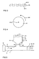
Figur 3 zeigt in einem Querschnitt eine Platte mit Löchern, an denen Zacken angeordnet sind. -
Figur 4 zeigt eine Scheibe mit einem Drehpunkt in der Mitte der Scheibe von oben -
Figur 5 zeigt in einem Querschnitt ein Auspuffrohr einer Verbrennungsmaschine. -
Figur 6 zeigt ein Ablaufdiagramm eines Verfahrens, nachdem das Ausgangsmaterial in das Abgas eingebracht wird. - Ausgangspunkt ist ein Abgas 1 eines Dieselmotors 15. Das Abgas 1 wird durch ein Auspuffrohr 2 in Strömungsrichtung 3 bewegt (
Figur 5 ). Im Abgas 1 sind aufgrund der Verbrennung in Gegenwart von molekularem Stickstoff Stickoxide enthalten. Diese Stickoxide werden mit Hilfe eines Katalysators 4 und Ammoniak als Reduktionsmittel aus dem Abgas 1 entfernt. Dazu wird pulverförmiger Harnstoff 5 vor dem Katalysator 4 in das Auspuffrohr 2 mit dem Abgas 1 eingebracht. - Ein Vorrat 51 des Harnstoffs 5 befindet sich in einem Vorratsbehälter 6, der über ein Anschlußstück 7 an das Auspuffrohr 2 angeschlossen ist. Der Vorratsbehälter 6 ist an das Anschlußstück 7 angeschraubt, das seinerseits an das Auspuffrohr 2 angeschweißt ist. Das Anschlußstück 7 ist ein Hohlkörper, durch den der Harnstoff 5 in das Abgas 1 des Auspuffrohres 2 gelangt. Anschlußstück 7 , Vorratsbehälter 6 und Auspuffrohr 2 sind so angeordnet, daß der Harnstoff 5 aufgrund der Schwerkraft in das Auspuffrohr 2 gelangt.
- Im Anschlußstück 7 befindet sich die Vorrichtung zum Einbringen des Harnstoffs 5 mit einem Mittel 8 zum Verändern eines Durchmessers 9 der Öffnung 10. Das Mittel 8 besteht aus zwei Scheiben 81 und 82 mit runden Löchern 811 und 821 (Lochblenden,
Figur 1 ). Ein Loch hat einen Lochdurchmesser von ca. 50 µm. Die Scheiben 81 und 82 sind so übereinander angeordnet, daß die ersten Löcher 811 der ersten Scheibe 81 und die zweiten Löcher 821 der zweiten Scheibe 82 die Öffnungen 10 mit variablen Durchmessern 9 bilden. Eine erste Scheibe 81 steht mit dem Vorrat 51 Harnstoffs 5 direkt in Kontakt. Diese Scheibe 81 ist drehbar um einen Drehpunkt 812 in der Mitte der Scheibe 81 gelagert (Figur 4 ). Durch Drehen der ersten Scheibe 81 verändern sich die Durchmesser 9 der Öffnungen 10. Zudem Verfügt die Scheibe 81 über Zacken 813, die direkt an den Löchern 811 der Scheibe 81 angeordnet sind (Figur 3 ). Die Zacken 813 zerkleinern beim Drehen 103 der Scheibe 81 vorhandene größere Partikel an Harnstoff 5, die nicht durch die Dosieröffnungen 10 passen würden. - Im Vorratsbehälter 6 ist ein Trockenmittel 11 vorhanden. Das Trockenmittel 11 sorgt dafür, daß ein Wassergehalt des Harnstoffs 5 so gering ist, daß der Harnstoff 5 rieselfähig ist. Das Trockenmittel 11 weist Silikagel auf.
- Zur Durchführung des Verfahrens 100 (
Figur 6 ) zum Einbringen von pulverförmigen Harnstoff 5 in das Abgas 1 ist nach dem Katalysator 4 ein Gassensor 12 für Stickoxide angeordnet (Figur 5). - Folgender Regelungsablauf findet beim Einbringen des Harnstoffs in das Abgas 1 statt: Ausgangspunkt ist ein Start des Dieselmotors 15. Mit dem Start wird ein Messen 101 von Stickoxid im Abgas 1 in Gang gesetzt. Mit Hilfe des Gassensors 12 wird ein Gehalt an Stickoxiden im Abgas 1 untersucht. Im Schritt 102 wird entsprechend dem Gehalt die ins Abgas 1 einzubringende Menge an Harnstoff 5 bestimmt. Im Schritt 103 wird die erste Scheibe 81 gegenüber der zweiten Scheibe 81 gedreht und somit der Durchmesser 9 der Dosieröffnungen 10 verändert. Ist der Gehalt an Stickoxiden zu hoch, wird der Durchmesser 9 erhöht und die Dosieröffnung 10 vergrößert. Durch die vergrößerte Dosieröffnung 10 wird mehr Harnstoff 5 in das Abgas 1 des Auspuffrohres 2 eingebracht. Es wird mehr Harnstoff 5 zu Ammoniak umgesetzt, was zu einer Verringerung des Gehalts an Stickoxiden im Abgas 1 führt. Verringert sich der Gehalt an Stickoxiden im Abgas 1, so wird der Druchmesser 9 der Dosieröffnung 10 durch Verdrehen der ersten Scheibe 81 verkleinert. Es gelangt weniger Harnstoff 5 in das Abgas 1.
- In einem weiteren Ausführungsbeispiel ist ein weiterer Gassensor 13 nach dem Katalysator 4 vorgesehen, der einen Gehalt an Ammoniak im Abgas 1 bestimmt. Dieser Gehalt wird ebenfalls zur Regelung der Menge an Harnstoff 5 herangezogen, die in das Abgas 1 eingebracht wird.
- In einer weiteren Ausführungsform ist auch die zweite Scheibe 82 drehbar um einen Drehpunkt in der Mitte der zweiten Scheibe 82 gelagert.
- Eine weitere Ausführungsform unterscheidet sich durch die Form der Löcher 811 und 821 der Scheiben 81 und 82. Dabei sind die Löcher der ersten und der zweiten Scheibe quasi komplementär gestaltet. Die ersten Löcher 811 der ersten Scheibe 81 sind kreisrunde Löcher 814. Die zweiten Löcher 821 der zweiten Scheibe 82 sind als segmentierte Ringe 815 ausgebildet.
- Eine weitere Ausführungsform verfügt überdies über ein Mittel 14 zur Kontrolle eines Vorrats 51 an Harnstoff 5. Dieses Mittel ist eine Lichtschranke, bestehend aus einer Licht emittierenden Photodiode und einem das Licht registrierenden Photodetektor. Die Lichtschranke 14 ist am Vorratsbehälter 6 angeordnet. Zwischen Photodiode und Photodetektor befindet sich der Vorrat 51 des Harnstoffs. Sobald der Vorrat 51 an Harnstoff 5 unter ein bestimmtes Niveau sinkt, wird ein Signal generiert, das dem Betreiber anzeigt, daß eine bestimmte Menge an vorhandenem Harnstoff 5 unterschritten ist. Im folgenden wird Harnstoff 5 in den Vorratsbehälter 6 nachgefüllt. Nachdem der Vorratsbehälter am Anschlußstück angeschraubt ist, wird in einer weiteren Ausführungsform der leere Vorratsbehälter 6 gegen einen neuen, mit Harnstoff 5 gefüllten Vorratsbehälter 6 ausgetauscht.
Claims (19)
- Vorrichtung zum Einbringen eines festen Ausgangsmaterials (5) eines Reduktionsmittels eines Stickoxids in ein in einem Auspuffrohr strömendes Abgas (1) durch mindestens eine Dosieröffnung (10), dadurch gekennzeichnet, daß die Vorrichtung ein Mittel (8) zu einem Verändern eines Durchmessers (9) der Dosieröffnung (10) aufweist.
- Vorrichtung nach Anspruch 1, wobei das Mittel (8) zu einem Verändern des Durchmessers (9) der Dosieröffnung (10) einen ersten Körper (81) mit mindestens einem ersten Loch (811) und mindestens einen zweiten Körper (82) mit mindestens einem zweiten Loch (821) aufweist und der erste Körper (81) und der zweite Körper (82) so aneinander angeordnet sind, daß die Dosieröffnung (10) durch das erste (811) und das zweite Loch (821) gebildet ist.
- Vorrichtung nach Anspruch 2, wobei mindestens ein Körper (81, 82) eine Platte ist.
- Vorrichtung nach Anspruch 3, wobei die Platte eine Scheibe (81) mit einem Drehpunkt (812) ist.
- Vorrichtung nach einem der Ansprüche 2 bis 4, wobei mindestens ein Körper (81, 82) an einem Vorrat (51) des Ausgangsmaterials (5) angeordnet ist.
- Vorrichtung nach einem der Anspruch 1 bis 5, wobei ein Mittel (813) zum Zerkleinern des Ausgangsmaterials (5) vorhanden ist.
- Vorrichtung nach Anspruch 6, wobei das Mittel (813) zum Zerkleinern mindestens eine Zacke ist, die in einen Vorrat (51) des Ausgangsmaterials (5) ragt.
- Vorrichtung nach einem der Anspruch 7, wobei die Zacke (813) an einem Loch (811, 821) angeordnet ist.
- Vorrichtung nach einem der Ansprüche 1 bis 8, wobei ein Mittel (14) zu einer Kontrolle des Vorrats (51) des Ausgangsmaterials (5) vorhanden ist.
- Verfahren zum Einbringen mindestens eines festen Ausgangsmaterials (5) mindestens eines Reduktionsmittels eines Stickoxids in ein Abgas (1) durch mindestens eine Dosieröffnung (10) mit einem veränderbaren Durchmesser (9), insbesondere Verfahren unter Verwendung einer Vorrichtung nach einem der Ansprüche 1 bis 9, mit folgenden Schritten:a) Bestimmen einer für eine Reduktion des Stickoxids benötigten Menge des Ausgangsmaterials undb) Verändern des Durchmessers der Dosieröffnung entsprechend der benötigten Menge des Ausgangsmaterials.
- Verfahren nach Anspruch 10, wobei das Bestimmen der benötigten Menge des Ausgangsmaterials ein Messen eines Gehalts an Stickoxid im Abgas beinhaltet.
- Verfahren nach Anspruch 10 oder 11, wobei mindestens ein erstes Loch (811) eines ersten Körpers (81) und mindestens ein zweites Loch (821) mindestens eines zweiten Körpers (82) die Dosieröffnung (10) mit einem veränderbaren Durchmesser (9) bilden und das Verändern des Durchmessers (9) durch ein Bewegen mindestens eines Körpers (81, 82) erfolgt.
- Verfahren nach Anspruch 12, wobei als Körper (81) eine Scheibe verwendet wird und das Bewegen des Körpers (81) durch ein Drehen (103) der Scheibe (81) um einen Drehpunkt (812) der Scheibe (81) erfolgt.
- Verfahren nach Anspruch 13, wobei das Drehen (103) mit einer konstanten Geschwindigkeit erfolgt.
- Verfahren nach Anspruch 12 oder 14, wobei die Scheibe (81) mit dem Vorrat (51) des Ausgangsmaterial (5) in Kontakt gebracht wird.
- Verfahren nach einem der Ansprüche 10 bis 15, wobei ein pulverförmiges Ausgangsmaterial (5) verwendet wird.
- Verfahren nach einem der Ansprüche 10 bis 16, wobei ein Ausgangsmaterial (5) verwendet wird, aus dem ein mindestens ein Stickstoffatom aufweisendes Reduktionsmittel gebildet wird.
- Verfahren nach Anspruch 17, wobei ein Ausgangsmaterial (5) verwendet wird, aus dem Ammoniak gebildet wird.
- Verfahren nach Anspruch 17 oder 18, wobei als Ausgangsmaterial (5) Harnstoff verwendet wird.
Applications Claiming Priority (2)
| Application Number | Priority Date | Filing Date | Title |
|---|---|---|---|
| DE19919913A DE19919913A1 (de) | 1999-04-30 | 1999-04-30 | Vorrichtung und Verfahren zum Einbringen eines festen Ausgangsmaterials eines Reduktionsmittels eines Stickoxids in ein Gasgemisch |
| DE19919913 | 1999-04-30 |
Publications (2)
| Publication Number | Publication Date |
|---|---|
| EP1048360A1 EP1048360A1 (de) | 2000-11-02 |
| EP1048360B1 true EP1048360B1 (de) | 2008-03-05 |
Family
ID=7906551
Family Applications (1)
| Application Number | Title | Priority Date | Filing Date |
|---|---|---|---|
| EP00109285A Expired - Lifetime EP1048360B1 (de) | 1999-04-30 | 2000-04-28 | Vorrichtung und Verfahren zum Einbringen eines festen Ausgangsmaterials eines Reduktionsmittels eines Stickoxids in ein Abgas |
Country Status (3)
| Country | Link |
|---|---|
| EP (1) | EP1048360B1 (de) |
| AT (1) | ATE387962T1 (de) |
| DE (2) | DE19919913A1 (de) |
Families Citing this family (3)
| Publication number | Priority date | Publication date | Assignee | Title |
|---|---|---|---|---|
| FR2900062B1 (fr) * | 2006-04-19 | 2008-06-27 | Tredi Sa | Procede et dispositif pour la reduction des nox dans des effluents gazeux d'incinerateur. |
| DE102006043954A1 (de) * | 2006-09-14 | 2008-03-27 | Volkswagen Ag | Verfahren zum Betreiben eines SCR-Katalysators sowie SCR-Katalysatorsystem |
| GB2591678B (en) * | 2018-10-02 | 2022-11-23 | Cummins Emission Solutions Inc | Systems and methods for dry chemical reductant insertion in aftertreatment systems |
Family Cites Families (3)
| Publication number | Priority date | Publication date | Assignee | Title |
|---|---|---|---|---|
| US2941841A (en) * | 1958-06-30 | 1960-06-21 | Carl M Davis | Flocking machine |
| DE4308542A1 (de) * | 1993-03-17 | 1994-09-22 | Man Nutzfahrzeuge Ag | Verfahren und Vorrichtung zur selektiven katalytischen Reduktion von NO¶x¶ in sauerstoffhaltigen Gasen |
| DE4423003C2 (de) * | 1993-07-06 | 1999-01-21 | Ford Werke Ag | Verfahren und Vorrichtung zum Reduzieren von NO¶x¶ in den Abgasen von Kraftfahrzeugverbrennungsmotoren |
-
1999
- 1999-04-30 DE DE19919913A patent/DE19919913A1/de not_active Withdrawn
-
2000
- 2000-04-28 DE DE50015004T patent/DE50015004D1/de not_active Expired - Lifetime
- 2000-04-28 EP EP00109285A patent/EP1048360B1/de not_active Expired - Lifetime
- 2000-04-28 AT AT00109285T patent/ATE387962T1/de not_active IP Right Cessation
Also Published As
| Publication number | Publication date |
|---|---|
| EP1048360A1 (de) | 2000-11-02 |
| ATE387962T1 (de) | 2008-03-15 |
| DE19919913A1 (de) | 2000-11-02 |
| DE50015004D1 (de) | 2008-04-17 |
Similar Documents
| Publication | Publication Date | Title |
|---|---|---|
| DE69005322T2 (de) | Verfahren zum Reduzieren der Stickoxyde aus Dieselmotorabgasen. | |
| EP2190587B1 (de) | Vielloch- oder bündeldüse | |
| DE60127164T2 (de) | DURCH NEBENSTROM-HARNSTOFFABBAU ERMÖGLICHTE, SELEKTIVE KATALYTISCHE NOx-REDUKTION | |
| EP2204231A1 (de) | Keramikpartikel | |
| DE4325968C2 (de) | Vorrichtung zum Kühlen von Gasen und gegebenenfalls Trocknen von dem Gas zugegebenen Feststoffteilchen | |
| DE69120812T2 (de) | Verfahren zur minimierung der konzentration an schadstoffen in verbrennungsgasen | |
| EP0555746A1 (de) | Vorrichtung zur katalytischen NOX-Reduktion | |
| DE29924992U1 (de) | Dosiersystem | |
| EP0615777A1 (de) | Verfahren und Vorrichtung zur selektiven katalytischen Reduktion von NOx in sauerstoffhaltigen Gasen | |
| DE2217131A1 (de) | Verfahren und vorrichtung zum chemischen konditionieren eines partikel mitfuehrenden gasstroms | |
| EP3615181B1 (de) | Vorrichtung und verfahren zur abgaswäsche | |
| DE19701384A1 (de) | Vorrichtung und Verfahren zum Schmelzblasspinnen | |
| DE2259763C3 (de) | Verfahren zur Reinigung von Stickstoffoxide enthaltenden Gasen und Vorrichtung zu dessen Durchführung | |
| DE102010050334B4 (de) | Verfahren und Vorrichtung zur nicht-katalytischen Entstickung von Abgasen von Verbrennungsanlagen | |
| EP2334916B1 (de) | Anordnung und verfahren zur abgasreinigung mittels eines reduktionsmittels | |
| EP1048360A1 (de) | Vorrichtung und Verfahren zum Einbringen eines festen Ausgangsmaterials eines Reduktionsmittels eines Stickoxids in ein Gasgemisch | |
| WO2007073881A1 (de) | Vorrichtung zum vermischen eines fluids mit einem grossen gasmengenstrom, insbesondere zum einbringen eines reduktionsmittels in ein stickoxide enthaltendes rauchgas | |
| DE2221644A1 (de) | Vorrichtung und Verfahren zum Bilden von Fluessigkeitstroepfchen | |
| DE3939197C2 (de) | ||
| WO2000066252A1 (de) | Verfahren und vorrichtung zum einbringen eines gasförmigen redukt ionsmittels eines stickoxids in ein gasgemisch | |
| EP1048340B1 (de) | Verfahren zum Einbringen eines Reduktionsmittels eines Stickoxids in ein Gasgemisch und Vorrichtung zum Durchführen des Verfahrens | |
| DE2141944C3 (de) | Verfahren zur Absorption von nitrosehaltigen Abgasen | |
| EP0300402B1 (de) | Verfahren zur Erzeugung extrem kleiner Partikel und Anwendung des Verfahrens | |
| WO1999029432A1 (de) | Verfahren und vorrichtung zur erzeugung eines feststoffaerosols | |
| EP2735364A1 (de) | Schmelzekonfektionierung mittels laminaren Strahlzerfalls |
Legal Events
| Date | Code | Title | Description |
|---|---|---|---|
| PUAI | Public reference made under article 153(3) epc to a published international application that has entered the european phase |
Free format text: ORIGINAL CODE: 0009012 |
|
| AK | Designated contracting states |
Kind code of ref document: A1 Designated state(s): AT DE FR GB IT |
|
| AX | Request for extension of the european patent |
Free format text: AL;LT;LV;MK;RO;SI |
|
| 17P | Request for examination filed |
Effective date: 20010502 |
|
| AKX | Designation fees paid |
Free format text: AT DE FR GB IT |
|
| 17Q | First examination report despatched |
Effective date: 20050223 |
|
| 17Q | First examination report despatched |
Effective date: 20050223 |
|
| RTI1 | Title (correction) |
Free format text: DEVICE AND PROCESS FOR METERING A SOLID SOURCE OF REDUCING AGENT FOR NITROGEN OXIDE INTO AN EXHAUST GAS |
|
| GRAP | Despatch of communication of intention to grant a patent |
Free format text: ORIGINAL CODE: EPIDOSNIGR1 |
|
| RAP1 | Party data changed (applicant data changed or rights of an application transferred) |
Owner name: ARGILLON GMBH |
|
| GRAS | Grant fee paid |
Free format text: ORIGINAL CODE: EPIDOSNIGR3 |
|
| GRAA | (expected) grant |
Free format text: ORIGINAL CODE: 0009210 |
|
| AK | Designated contracting states |
Kind code of ref document: B1 Designated state(s): AT DE FR GB IT |
|
| REG | Reference to a national code |
Ref country code: GB Ref legal event code: FG4D Free format text: NOT ENGLISH |
|
| REF | Corresponds to: |
Ref document number: 50015004 Country of ref document: DE Date of ref document: 20080417 Kind code of ref document: P |
|
| ET | Fr: translation filed | ||
| PLBE | No opposition filed within time limit |
Free format text: ORIGINAL CODE: 0009261 |
|
| STAA | Information on the status of an ep patent application or granted ep patent |
Free format text: STATUS: NO OPPOSITION FILED WITHIN TIME LIMIT |
|
| 26N | No opposition filed |
Effective date: 20081208 |
|
| PG25 | Lapsed in a contracting state [announced via postgrant information from national office to epo] |
Ref country code: AT Free format text: LAPSE BECAUSE OF NON-PAYMENT OF DUE FEES Effective date: 20080428 |
|
| REG | Reference to a national code |
Ref country code: FR Ref legal event code: CD Owner name: JOHNSON MATTHEY CATALYSTS GERMANY GMBH, DE Effective date: 20120615 |
|
| REG | Reference to a national code |
Ref country code: DE Ref legal event code: R082 Ref document number: 50015004 Country of ref document: DE Representative=s name: FDST PATENTANWAELTE FREIER DOERR STAMMLER TSCH, DE |
|
| REG | Reference to a national code |
Ref country code: DE Ref legal event code: R081 Ref document number: 50015004 Country of ref document: DE Owner name: JOHNSON MATTHEY CATALYSTS (GERMANY) GMBH, DE Free format text: FORMER OWNER: ARGILLON GMBH, 96257 REDWITZ, DE Effective date: 20121004 Ref country code: DE Ref legal event code: R082 Ref document number: 50015004 Country of ref document: DE Representative=s name: FDST PATENTANWAELTE FREIER DOERR STAMMLER TSCH, DE Effective date: 20121004 |
|
| REG | Reference to a national code |
Ref country code: FR Ref legal event code: PLFP Year of fee payment: 17 |
|
| REG | Reference to a national code |
Ref country code: FR Ref legal event code: PLFP Year of fee payment: 18 |
|
| REG | Reference to a national code |
Ref country code: FR Ref legal event code: PLFP Year of fee payment: 19 |
|
| PGFP | Annual fee paid to national office [announced via postgrant information from national office to epo] |
Ref country code: IT Payment date: 20190321 Year of fee payment: 20 Ref country code: FR Payment date: 20190325 Year of fee payment: 20 Ref country code: GB Payment date: 20190325 Year of fee payment: 20 |
|
| PGFP | Annual fee paid to national office [announced via postgrant information from national office to epo] |
Ref country code: DE Payment date: 20190220 Year of fee payment: 20 |
|
| REG | Reference to a national code |
Ref country code: DE Ref legal event code: R082 Ref document number: 50015004 Country of ref document: DE Representative=s name: BARDEHLE PAGENBERG PARTNERSCHAFT MBB PATENTANW, DE |
|
| REG | Reference to a national code |
Ref country code: DE Ref legal event code: R071 Ref document number: 50015004 Country of ref document: DE |
|
| REG | Reference to a national code |
Ref country code: GB Ref legal event code: PE20 Expiry date: 20200427 |
|
| PG25 | Lapsed in a contracting state [announced via postgrant information from national office to epo] |
Ref country code: GB Free format text: LAPSE BECAUSE OF EXPIRATION OF PROTECTION Effective date: 20200427 |