EP1048190B1 - Electronic lamp ballast - Google Patents
Electronic lamp ballast Download PDFInfo
- Publication number
- EP1048190B1 EP1048190B1 EP98964410A EP98964410A EP1048190B1 EP 1048190 B1 EP1048190 B1 EP 1048190B1 EP 98964410 A EP98964410 A EP 98964410A EP 98964410 A EP98964410 A EP 98964410A EP 1048190 B1 EP1048190 B1 EP 1048190B1
- Authority
- EP
- European Patent Office
- Prior art keywords
- circuit
- lamp
- gas discharge
- electronic ballast
- control circuit
- Prior art date
- Legal status (The legal status is an assumption and is not a legal conclusion. Google has not performed a legal analysis and makes no representation as to the accuracy of the status listed.)
- Expired - Lifetime
Links
Images


Classifications
-
- H—ELECTRICITY
- H05—ELECTRIC TECHNIQUES NOT OTHERWISE PROVIDED FOR
- H05B—ELECTRIC HEATING; ELECTRIC LIGHT SOURCES NOT OTHERWISE PROVIDED FOR; CIRCUIT ARRANGEMENTS FOR ELECTRIC LIGHT SOURCES, IN GENERAL
- H05B41/00—Circuit arrangements or apparatus for igniting or operating discharge lamps
- H05B41/14—Circuit arrangements
- H05B41/26—Circuit arrangements in which the lamp is fed by power derived from dc by means of a converter, e.g. by high-voltage dc
- H05B41/28—Circuit arrangements in which the lamp is fed by power derived from dc by means of a converter, e.g. by high-voltage dc using static converters
- H05B41/295—Circuit arrangements in which the lamp is fed by power derived from dc by means of a converter, e.g. by high-voltage dc using static converters with semiconductor devices and specially adapted for lamps with preheating electrodes, e.g. for fluorescent lamps
- H05B41/298—Arrangements for protecting lamps or circuits against abnormal operating conditions
- H05B41/2981—Arrangements for protecting lamps or circuits against abnormal operating conditions for protecting the circuit against abnormal operating conditions
Definitions
- the present invention relates to an electronic ballast for operation at least one fluorescent or gas discharge lamp according to the preamble of Claim 1.
- Such an electronic ballast is for example from EP-B1-0338 109 known.
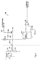
- Fig. 10 shows the basic structure of this electronic ballast.
- the electronic ballast shown in FIG. 10 first comprises a circuit A, which is connected to the AC network.
- This circuit A serves as an RF harmonic filter to reduce the harmonic harmonics of the mains frequency as well for radio interference suppression.
- the circuit A is followed by a rectifier circuit B which supplies the mains voltage converted into a rectified intermediate voltage and this via a harmonic filter C, which serves to smooth the intermediate voltage, an inverter circuit D supplies.
- This inverter D serves as a controllable AC voltage source and converts the DC voltage of the rectifier B into a variable AC voltage.
- the inverter D generally comprises two controllable switches (not shown), for example MOS field effect transistors.
- the two switches are in the form of a Half-bridge circuit interconnected and are using an appropriate Bridge driver alternately controlled such that one of the switches on and one other is off.
- the two inverter switches are connected in series connected between a supply voltage and ground, being at the common Node between the two inverter switches a load circuit or Output circuit E is connected in which a gas discharge lamp or Fluorescent lamp G is arranged.
- This output circuit E includes one Series resonance circuit via which the "chopped" high-frequency AC voltage of the Inverter D of the fluorescent lamp G is supplied.
- the Lamp electrodes of the fluorescent lamp G preheated to increase the lamp life extend.
- the preheating can, for example, with the help of a heating transformer take place, the primary winding is connected to the series resonance circuit, while the Secondary windings of the heating transformer coupled to the individual lamp filaments are. In this way it is possible to use the lamp filaments even in the ignited mode To supply energy.
- the frequency of the inverter D supplied AC voltage compared to the resonance frequency of the series resonance circuit of the output circuit E changed such that the applied to the gas discharge lamp G. Voltage does not cause the lamp to ignite.
- the electronic ballast has a control circuit F on, which monitors various circuit sizes of the electronic ballast and if a limit value is exceeded, a corresponding control signal for the Inverter D generates the frequency of those generated by the inverter D. AC voltage to change depending on the detected fault.
- the control circuit F, the lamp voltage, the preheating voltage Lamp operating current, the impedance phase angle of the output circuit E or that of Monitor the DC voltage generated by the rectifier B and the inverter frequency adjust so that the lamp voltage, the preheating voltage or the lamp current do not exceed a predetermined limit value that was taken from the rectifier B.
- DC power is as constant as possible or a capacitive operation of the series resonance output circuit E is avoided.
- a simple procedure for choosing a suitable lamp start is in the GB 2 053 592 A.
- the present invention is based on the object of the prior art improve known methods for selecting the type of lamp start and to ensure reliable functioning at the same time.
- the electronic ballast has a control circuit which or operating size of the electronic ballast is monitored and dependent on the value of this circuit size, the electronic ballast either with a Operates preheating or without preheating.
- the electronic Ballast is designed such that it automatically when a new or Restart detects whether the correspondingly controlled gas discharge lamp previously was already in operation, so that the lamp electrodes may need to be preheated Gas discharge lamp can be dispensed with.
- the control circuit detects when the electronic ballast automatically one of those in the energy storage circuit remaining charge corresponding voltage - this being a measure of the
- the electronic ballast is switched off - and compares it with the help of Comparator means with a reference value. Is the at the time of restart of the electronic ballast still high enough charge controls the Control circuit on the gas discharge lamp without preheating. Otherwise, a Preheating operation carried out.
- the energy storage circuit for example by a the control circuit connected RC element can be formed during operation charged to a predetermined (fixed) supply voltage potential.
- the control circuit Output signal of the state hold circuit for the commissioning of the Evaluates gas discharge lamp.
- charging the energy storage circuit has a predetermined and thus known supply voltage potential as a result that temporal behavior of the monitored circuit size fully known and from external influences as well as possible dimming settings of the lamp at the time of the Switching off the ballast is independent.
- temporal behavior of the monitored circuit size fully known and from external influences as well as possible dimming settings of the lamp at the time of the Switching off the ballast is independent.
- it is possible to design the circuit so that after a certain predetermined switch-off time the lamp regardless of the to this In any case, the present coil temperature started with preheating mode becomes.
- a corresponding standard which always starts with a lamp after a switch-off period of more than 400 ms Preheat operation requires to be met.
- the second advantage of the circuit according to the invention is that it ensures is that the evaluation of the comparison result only during the lamp start a change in the output signal is carried out at a later time however, it has no influence on further operations.
- the Gas discharge lamp can be put into operation as quickly as possible by clicking on one unnecessary preheating mode is dispensed with.
- the lamp electrodes of the gas discharge lamp are protected because they are excessive Heating of the lamp electrodes is also prevented. This ensures that sufficient even when the gas discharge lamp is started up without preheating Temperature of the lamp electrodes for igniting the gas discharge lamp is present.
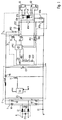
- the electronic ballast shown in FIG. 1 first comprises a circuit A, which on the input side to a supply voltage, for example a mains voltage, is connected and used for radio interference suppression.
- Circuit A is in the usual way constructed and includes, for example, capacitive input filters and possibly. Harmonic chokes.
- a capacitor C2 and a are only exemplary Symmetry transformer L1 shown, with a surge arrester or a VDR with the designation F1 can be connected in parallel.
- the circuit B following the circuit A comprises one Full wave rectifier bridge with diodes V1 - V4.
- the rectifier circuit B converts the supply AC voltage present on the input side into a rectified one Intermediate voltage around.
- the rectifier circuit B can therefore be omitted if that electronic ballast is operated with DC voltage.
- the following circuit part C is used for harmonic filtering and smoothing of the intermediate voltage supplied to the rectifier B.
- the circuit C shown in Fig. 1 includes, for example, capacitors C3, C11, a diode V5, a coil L2, one MOS field-effect transistor T1 and an integrated circuit Control circuit IC1.
- the control circuit IC1 is at a supply voltage potential VCC connected and can be connected to the other circuit elements in such a way that it receives different voltage potentials U or currents I.
- the one in Fig. 1 The structure of the circuit C shown is of course to be understood purely as an example.
- an inverter circuit D controlled as the essential elements two in series between one Supply voltage line and ground switched controllable switches, in the present Example in the form of MOS field effect transistors T2 and T3.
- the two Inverter switches T2, T3 are connected to form a half bridge and are each controlled with the aid of a control circuit IC2 designed as an integrated circuit, i.e. opened and closed.
- the control circuit IC2 thus also takes over Function of a bridge driver and is connected to a corresponding one Supply voltage line VCC connected or coupled to it.
- the Inverter circuit D generates depending on that of rectifier circuit B. generated rectified intermediate voltage an AC voltage with variable Frequency and / or duty cycle.
- the inverter D is in the usual way built and its function is well known, so here on another Explanation can be omitted. It is only important at this point that the Control circuit IC2 the two depending on the control signals supplied Inverters T2 and T3 control alternately, so that at the connection point a "chopped", high-frequency between the two inverter switches T2 and T3 AC voltage occurs.
- the load circuit E is for the connection of two Gas discharge lamps G1, G2 designed in tandem configuration. Of course leaves load circuit E also change in such a way that only one gas discharge lamp or more than two gas discharge lamps can be operated.
- the load circuit E is a series resonance circuit consisting of a Has resonant circuit coil L3 and a resonant circuit capacitor C14.
- This Series resonance circuit or resonance circuit coil L3 is at the connection point connected between the two inverter switches T2 and T3 and the Resonant circuit capacitor C14 is arranged to be parallel to that operating gas discharge lamp or the gas discharge lamps G1, G2 to be operated is switched.
- the high-frequency AC voltage generated by the inverter D. is supplied to the gas discharge lamps G1 and G2 via the series resonance circuit.
- the two are Gas discharge lamps G1 and G2 in tandem configuration to the load circuit E or that electronic ballast connected.
- the ignition voltage to the gas discharge lamps G1, G2 these are preheated to extend the life of the gas discharge lamps.
- a heat exchanger L4 is provided whose primary winding is in Series is connected to the resonant circuit capacitor C14, while the Secondary winding, the lower filament of the upper gas discharge lamp G1 and the upper one Helix of the lower gas discharge lamp G2 connects.
- preheating mode becomes the frequency of the AC voltage supplied by the inverter E. the resonance frequency of the series resonance circuit set such that the above Resonant circuit capacitor C14 and thus across the gas discharge lamps G1 and G2 applied voltage does not cause ignition of the gas discharge lamps.
- the capacitor C15 shown in FIG. 1 adapts the Preheating voltage in the tandem configuration shown in Fig. 1 Gas discharge lamps G1 and G2.
- the electronic shown in Fig. 1 goes Ballast in the actual operating phase, in which the frequency of the Inverter D supplied AC voltage continuously, for example is set that a constant as possible by the gas discharge lamps G1, G2 Lamp current flows or a constant as possible on the gas discharge lamps Lamp voltage is present. As will be explained in more detail below, this is shown in FIG.
- a circuit module serves as the heart the previously mentioned control circuit IC2 and several external components as external circuitry of the control circuit IC2 comprises.
- the main external Components are six resistors R10, R13 - R16 and R21, R22 and two Capacitors C7 and C17. As shown in Fig. 1, the individual are external Components connected to respective input connections of the control circuit IC2.
- the External components connected to the control circuit IC2 serve primarily for Detection of certain circuit sizes of the electronic ballast, so that this can be evaluated in the control circuit IC2.
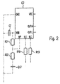
- FIG. 2 shows an enlarged illustration of the control circuit IC2 shown in FIG. 1 as well as the external wiring of the individual input connections of the control circuit IC2. 2 are only the essential connections and external components shown.
- the control circuit IC2 is advantageously as application specific integrated circuit, ASIC) and in a multi-pole SMD housing (Surface Mounted Device) accommodated.
- the control circuit IC2 is both for operation of an individual lamp output circuit E and also for the operation of one for one in FIG. 1 Tandem configuration shown with several gas discharge lamps designed load circuit E suitable.
- the Control circuit IC2 several connections, which have the following functions.
- To the Connection GND is the reference potential, i.e. the ground potential, for the individual analog and Digital function blocks of the control circuit IC2 created. 1 shows that the ground potential of the entire electronic ballast over a Coupling capacitor C1 is grounded.
- At the connection VDD, which over the Coupling capacitor C7 is connected to the ground potential (see. Fig. 1), the internal generated supply voltage for the individual analog and digital function blocks of the Control circuit IC2 provided.
- the NP connection serves, as will be explained in more detail below for external setting and detection of the preheating method, i.e. to Selection between a cold start and warm start operation.
- connection NP connected externally in such a way that a dynamic choice of the preheating method is possible.
- the connection VL1 is detected via those shown in FIG. 1 and partly in FIG. 2 Resistors R10 and R14, R15 divided the lamp voltage of the Gas discharge lamps G1, G2 and thus primarily serves Lamp voltage monitoring.
- the connection ILC is used analogously with the aid of FIG. 1 and resistors R13 and R16 shown partially in Fig. 2 for monitoring the Output circuit or load circuit current (choke current) or for monitoring the through the gas discharge lamps G1, G2 after their ignition flowing lamp current by with the help of the shunt resistor R16 a voltage proportional thereto and the Control circuit is supplied via the connection ILC.
- connection VL1 thus serves for voltage monitoring, while the ILC connection is used for current monitoring.
- the Both output connections OUTL and OUTH serve to control the one in FIG. 1 shown low or high half-bridge switch T3 or T2.
- TTL level control signals at the output connections OUTL and OUTH for switching the two inverter switches T2 and T3 on and off provided.
- the connection VCC of the control circuit IC2 is finally the central one Supply voltage connection of the control circuit IC2.
- the supply voltage range can include 10-18V, for example. Furthermore controls the control circuit IC2, the inverter switches T2 and T3 such that from the inverter circuit D an AC voltage of variable frequency on the output side is generated with an operating frequency range of 40-80 kHz, for example.
- the control circuit IC2 forms the heart of the whole shown in FIG. 1 electronic ballast and therefore includes a variety of different Functions.
- the preheating method for the connected gas discharge lamp (s) dynamically defined and between a cold start and a warm start operation can be changed.
- the control circuit IC2 for a defined preheating operation with a defined one Preheating time and a defined preheating current.
- the control circuit IC2 also ensures a predefined ignition operation with a specified ignition time and a specified Ignition voltage.
- the connections ILC or VL1 of the control circuit IC2 can for example the preheating current and the lamp operating current or the lamp voltage recorded and regulated to a constant value as possible.
- a capacitive operation of the Load circuit E monitors.
- the occurrence can also occur via the voltage connection VL1 of a constant light effect in a connected gas discharge lamp G1, G2 recognized become.
- the occurrence of a Gas defect which leads to an overvoltage on the corresponding gas discharge lamp leads, recognized and accordingly the electronic ballast in this case be switched off.
- a special function of the control circuit IC2 is recognition a lamp change, the. In the tandem configuration shown in FIG Lamp change detection is in particular independent of the changed lamp, i.e. both the upper gas discharge lamp G1 and the lower one can be changed Gas discharge lamp G2 can be detected.
- control circuit IC2 preferably digitally implemented sequence control implemented, which ensures that the gas discharge lamp (s) connected to the electronic ballast in accordance with predetermined operating states are controlled, with an operating state in a new operating state only if at least one specific condition is met can be changed.
- IC2 preferably digitally implemented sequence control implemented, which ensures that the gas discharge lamp (s) connected to the electronic ballast in accordance with predetermined operating states are controlled, with an operating state in a new operating state only if at least one specific condition is met can be changed.
- IC2 preferably digitally implemented sequence control implemented, which ensures that the gas discharge lamp (s) connected to the electronic ballast in accordance with predetermined operating states are controlled, with an operating state in a new operating state only if at least one specific condition is met can be changed.
- IC2 preferably digitally implemented sequence control implemented, which ensures that the gas discharge lamp (s) connected to the electronic ballast in accordance with predetermined operating states are controlled, with an operating state in a new operating state only if at
- control circuit has IC2 other functions, all of which are given below with reference to the attached Drawing to be explained in more detail.
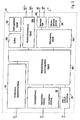
- Fig. 3 shows a block diagram of the internal structure of the previously described Control circuit IC2.
- a module 100 is initially coupled to the power connection ILC, which among other things to the previously explained current detection and capacitive current detection of the Load circuit serves.
- the evaluation of the current sensed via the connection ILC takes place in particular with the aid of a controller formed by a comparator circuit. To the To keep circuit complexity really low, this comparator circuit will also do that received by the voltage terminal VL1 of the control circuit IC2 and by one Module 200 supplied and evaluated voltage signal.
- the module 200 serves in particular for detecting the lamp voltage, for rectifying effect detection and for lamp change detection.
- the NP connection is another module 300 coupled, which to detect the warm or cold start operation during preheating the gas discharge lamp (s) to be controlled and to implement a dynamic one Preheating is used.
- a Voltage regulator module 400 connected, which has an internal voltage regulator, which is a regulated, very precise voltage for the power supply of all internal Provides function blocks.
- Another module 500 serves as a source for all required reference quantities, i.e. Reference voltages and reference currents in which Control circuit IC2.
- An oscillator 600 serves as an internal clock of the control circuit IC2, a time base generator 700 coupled to it depending on the predetermined one Clock of the oscillator 600 internal time variables for the sequential control of the Control circuit IC2, e.g.
- Another module 800 is used to implement the sequential control of the individual operating states of the entire electronic ballast and works closely with another module 900, which is used for measuring phase control.
- the module 900 is used in particular for event-filtered evaluation of certain error quantities of the electronic Ballast and for measuring phase-dependent control of all switches individual function blocks of the control circuit IC2.
- the sequencer 800 evaluates the event-filtered status messages from the measuring phase controller 900 and controls depending on the time variables specified by the time base generator 700 individual operating states of the electronic ballast or the control circuit IC2.
- the control circuit IC2 assigns a further module 1000 Inverter control on. With the help of this module 1000 the Measuring phase control 900 delivered frequency setting signals into corresponding Control signals for the upper inverter switch (via the output connection OUTH) or the lower inverter switch (via the output connection OUTL).
- the control circuit IC2 can be implemented both analog and digital Function blocks include.
- the digital part comprises the ASIC trained control circuit IC2, the time base generator 700, the sequencer 800, the measuring phase control 900 and the inverter control 1000.
- the control circuit IC2 be equipped such that the digital part with respect to Space requirement of the control circuit IC2 corresponds to the analog part.
- FIG. 4 shows a detailed circuit diagram of the current detection module shown in FIG. 3 100.
- Fig. 4 are also the external with the power connector ILC of the control circuit connected resistors R13 and R16, which are also shown in FIG. 1.
- a reference current Iref1 is added to the signal detected at the current connection ILC, to ensure that the signal to be processed by the current sensing module 100 is always in the working voltage range of the control circuit.
- an integrator circuit 105 is provided for integration of the input signal fed to it.
- the entire functional block 105 is such realizes that the integrator function both for measuring the lamp current (via the Connection ILC) in normal operation, as well as for rectification effect detection (via the Connection VL1) can be used.
- the integrator circuit 105 may have sample and hold elements, which alternately each Period of the internal clock generator (cf. module 600 in FIG. 3) the input signal of the Scan integrators. The charge thus stored in the sample and hold members turns on an integration amplifier of the integrator circuit 105. This process is repeated cyclically.
- the integrator 105 may have an internal controllable switch that does the above bridged sample and hold bridges and during the duration of the offset adjustment of the Integrators 105 is closed. This way, any signal, in particular the signal present at the input connection ILC via the switch S105 or a reference voltage potential for rectification effect detection from the voltage block 200 via switch S107, during the initialization phase on the actual Integration amplifier can be created.
- the actual integration amplifier of the integrator 105 has the task of Integrate the current measurement signal at the ILC connection in a precisely controlled time. In the case, that the current measurement signal present at the ILC connection from the integration amplifier Integrator circuit 105 is integrated, the switch S105 is closed, while for the case of the rectification effect evaluation that supplied via the switch S107 Reference potential for the rectification effect evaluation at the integrator circuit 105 is applied.
- a comparator 103 serves as the actual controller, which performs the required setpoint / actual value comparison performs and is connected to the output integrators 105.
- this comparator 103 shown in FIG. 4 makes it possible to use the comparator 103 very flexible to use.
- a switch S124 can use different comparator voltages or reference values to the comparator 103 can be added or applied, reference voltages being exemplary in FIG. 4 Vref1 - Vref6 are shown.
- the reference potential corresponds to Vref1 and Vref2 for example a desired preheating voltage during a Vor carving worriessShes.
- the controllable switch S124 the reference voltage Vref1 or Vref2 to the comparator 103 created so that the currently present on the ILC connector and not integrated Measuring signal is compared with the reference value Vref1 or Vref2 respectively applied.
- the reference potential Vref3 corresponds to that Integration start value of the integration amplifier of the integrator 105, so that when concerns of this reference potential Vref3, the comparator 103 real changes the Integration result can capture.
- the reference potentials Vref4 or Vref6 can a positive or negative limit for the supplied via switch S107 and correspond to the integrated lamp voltage of the connection VL1, so that by Comparison with these two limit values when the integration result is exceeded the occurrence of a rectification effect reliably in positive or negative direction to be able to recognize.
- the further reference potential Vref5 used which is switched on in the rectification effect detection and the Output or start value for the integration of those supplied via switch S107 Lamp voltage corresponds.
- the reference potentials Vref3 or Vref5 predetermined start values of the integration amplifier of the integrator 105 can thus, with the aid of the comparator 103, actually be relative to the corresponding one Starting value of the change in the corresponding integration variable determined become.
- the output signal of the comparator 103 becomes that shown in FIG. 3 Measuring phase control 900 supplied, which evaluates this and depending on the current measurement phase evaluated differently. This is how the measuring phase control ensures 900 for example for a corresponding adjustment of the output frequency of the Inverter of the electronic ballast, if that of the comparator 103 monitored current measurement signal of the connection ILC from the specified setpoint Vref3 differs.
- the measurement phase control an event-filtered signal, which indicates whether there is a rectification effect in a connected gas discharge lamp or Not. This signal is provided by the flow control block 800 shown in FIG. 3 evaluated and for operating state control of the entire electronic Ballast used.
- the measurement signal present at the connection ILC can also be under Bypassing the integrator circuit 105 are monitored and evaluated, e.g. one capacitive operation of the load circuit of the electronic ballast to detect.
- a detector for detecting a capacitive current flowing in the load circuit be provided, for example, the phase angle of the load circuit, i.e. the Phase difference between the load circuit voltage and the load circuit current, determined (Kapazitivstromer extended).
- the result of this monitoring or evaluation can be fed to the measuring phase controller 900.
- FIG. 5 a shows an enlarged illustration of the essential elements of the one already in FIG. 1 shown inverter D and the load circuit E.
- Fig. 5a assumed that only one gas discharge lamp G1 connected.
- 5a shows the two inverter switches connected in series T2 and T3 shown.
- the load circuit with its Series resonant circuit at the connection point between the two Inverter switches T2 and T3 connected, i.e. the resonance circuit coil L3 is with the resonant circuit capacitor C14 in parallel with the lower inverter switch T3 connected.
- the resonant circuit capacitor C14 is also parallel to that Gas discharge lamp G1 connected.
- free-wheeling diodes V11 and V12 are connected in parallel to protect the respective Serve as an inverter switch.
- 5b shows on the one hand the switch-on states of the two inverter switches T2 and T3 as well as the current profile of the current I L3 flowing through the choke L3 and the time profile of the voltage potential V L occurring at the connection point between the two inverter switches T2 and T3.
- a current flows in the freewheeling diode of the inverter switch to be switched on and the inverter half bridge switches the resonant load circuit inductively, ie the voltage or potential V L leads the choke current I L3 .
- the capacitive switching of the resonance load of the resonance load circuit is the capacitive switching of the resonance load of the resonance load circuit.
- FIG. 5a shows the course of the individual currents I 1 -I 4 that occur during the time intervals t 1 -t 4 shown in FIG. 5b in the case of an inductive or capacitive inductor current I L3 .
- the above-mentioned phenomenon occurs in particular at load circuit voltages V L with an output frequency close to the resonance frequency of the series resonance circuit, which is particularly the case when the gas discharge lamp G1 is ignited, with an inductive current initially flowing in the load circuit which leads to heating of the coil L3 leads. Due to the heating of the coil L3, its inductance decreases, so that a transition suddenly occurs from the inductive area to the faulty capacitive area.
- the height of the current amplitude at the time the lower one is switched on Inverter switch T3 detected because in this case the polarities of the to be detected Measured values favorable for processing within the ASIC Control circuit IC2 are. If the detected current value is below that by the corresponding reference potential predetermined limit value, is based on the presence of a capacitive operation of the load circuit closed, and there can be an output signal with are generated at a high level, which is shown in FIG Measurement phase control block 900 evaluated and finally from that also in FIG. 3rd inverter control block 1000 shown in drive signals for the two Inverter switches T2 and T3 are implemented with an increased frequency alternately switched on and off to increase the working frequency and thus to counteract capacitive operation.
- FIG. 6 shows the internal structure of the voltage detection block 200 and the external one coupled to terminal VL1 of voltage detection block 200 Wiring the control circuit.
- a series resistor R10 on the one hand with the connection VL1 and on the other hand with a voltage divider consisting of resistors R14 and R15 is coupled, the two voltage divider resistors R14 and R15 parallel to the Gas discharge lamp G1 or to those connected in tandem in FIG. 1 Gas discharge lamps G1 and G2 are switched.
- FIG. 6 assumed that, in contrast to FIG. 1, only one gas discharge lamp G1 is controlled, to which the resonant circuit capacitor C14 is also connected in parallel.
- the two resistors R14 and R15 have the task of acting on the gas discharge lamp G1 to divide the applied voltage so that with the help of the connection point between the resistors R14 and R15 attacking resistor R10 for the Lamp voltage representative measurement signal to the voltage terminal VL1 Voltage detection blocks 200 can be supplied.
- the three external resistors R10, R14 and R15 are advantageously variable, see above that - analogous to the power connection ILC (cf. resistors R13, R16) - via one Connection of the control circuit completely different from each other A total of three different control variables of the electronic ballast at times can be set or controlled using the same controller.
- setting the resistance values of the resistors R10, R14 and R15 can depending on the type of lamp currently being used or on the instant used electronic ballast the setpoints for the regulation of the three different control variables can be set or specified.
- the following sizes of the electronic ballast can be set: the maximum Lamp voltage positive / negative, the amplitude of the AC voltage component of the Lamp voltage signal and the signal increase of the lamp voltage signal for Rectifying effect evaluation.
- an internal reference current source is again provided, which the measuring signal present at the voltage connection VL1 with an additional internal Current Iref2 applied.
- the reference current Iref2 using the controllable switch S207 only activated during the evaluation of the rectification effect, i.e. closed. All other evaluations connected to the VL1 connection refer to the signal present at connection VL1 without additional reference current Iref2, i.e. without DC offset. Accordingly, during the rectification effect evaluation all other detectors on the VL1 connection deactivated, otherwise they are wrong would deliver results.
- gas discharge lamps occur due to wear and tear on the heating coil at the end of its service life
- Gas discharge lamps have the effect that the lamp electrodes change over time wear unevenly, i.e. the removal of the emission layers on the Lamp electrodes are different. Due to the different wear of the Lamp electrodes produce differences in the emissivity of the two Lamp electrodes. This has the consequence that when operating the corresponding Gas discharge lamp from one lamp electrode to another a higher current flows than vice versa. The course of the lamp current over time thus shows an excessive increase Half wave on.
- the previously explained rectification effect also has the consequence that the stronger worn electrode, which has a higher work function than the other electrode, heated up more than the other electrode when starting the gas discharge lamp.
- Work function is generally called the minimum energy required to solve a problem Electrons from a metal, in this case from a lamp electrode, required is.
- the heating of the lamp electrode described above can be particularly important in the case of lamps with a small diameter become so strong that parts of the lamp glass bulb melt can.
- each controlled lamp is switched on Occurrence of a rectification effect monitored so that when a Rectification effect can be reacted accordingly.
- the switch S207 shown in FIG. 6 is advantageously switched on some time before expected zero crossing of the lamp voltage signal present at connection VL1 closed, so that transients caused by the capacitor C201 Cannot additionally falsify the measurement signal. Exactly to the calculated zero crossing of the Lamp voltage, switch S201 is opened again. That on the in Figs. 4 and 6th Switch S107 signal shown corresponds at this time to AC voltage amplitude at terminal VL1, while the DC component of the switch S107 applied signal corresponds to the added reference voltage Vref8. By Finally, as previously explained, closing switch S107 will thus prepared measurement signal of the connection VL1 that shown in Fig. 4 Integrator circuit 105 supplied.
- the switching state of the switch S107 will be as well all other controllable switches of the entire control circuit IC2 from that in FIG. 3 phase control 900 shown controlled.
- the individual switches shown in Fig. 4 are closed or opened by the measuring phase control 900 in such a way that with With the aid of the comparator 103 an averaged over the upstream integrator circuit Evaluation of the current measurement signal present at the ILC connection or that at the connection VL1 applied voltage measurement signal is possible.
- the comparator can also 103 by corresponding actuation of the controllable switches of the one shown in FIG. 4
- Current detection blocks 100 also directly bypassing the integrator circuit with the Current measurement connection ILC are connected to the peak value of the current measurement signal evaluate or regulate at the ILC connection.
- the measurement phase control 900 which of the measurement or control states is assumed.
- That realized in the present control circuit IC2 Rectifier effect detection principle provides that the voltage connection VL1 detected lamp voltage using the integrator circuit of the one shown in FIG Current detection blocks 100 integrated and then the deviation from one predetermined setpoint is evaluated. In particular, that of the lamp voltage corresponding measurement signal over a full period or a multiple of a full period integrated the lamp voltage and then the deviation of the Integration result evaluated from the original integration start value.
- the comparator 103 the integration start value by applying the corresponding reference potential Vref5 supplied.
- Vref5 can, for example 3.0V
- as a positive reference potential Vref4 a value of 4.0V and as negative reference potential Vref6 a value of 2.0V can be used.
- the output signal of the comparator shown in FIG. 4 in turn becomes the Measuring phase control 900 supplied, the one after detection of a rectification effect corresponding status message or error message to the one shown in FIG. 3 Sequence control 800 delivers.
- the Measurement phase control 900 an event-filtered revision of this error message by and ensures that only then will an error message indicating the rectification effect be sent to the Sequence control 800 is output if the rectification effect is prolonged Period occurs continuously.
- the measurement phase controller 900 only provides a rectification effect error message the sequencer 800 if 32 times from the comparator 103 shown in FIG a rectification effect is detected successively every 255th period of the lamp voltage.
- the occurrence of a rectification effect only taken into account in the operating state of the electronic ballast, because for example, during the preheating phase, the occurrence of a rectification effect is not Shutdown of the system.
- the Rectification effect detection in particular by the fact that during the individual half-waves the lamp voltage or the dependent clock pulse size (high-frequency) reference clock are counted and compared with each other, the counted clock pulses are dependent on the duration of the respective half-wave. If there is no rectification effect, they are correct during the positive and negative Half-waves counted clock pulses. If there is a rectification effect, give way on the other hand, the clock pulses counted during the positive and negative half-waves from each other.
- 11a shows a circuit implementation of this exemplary embodiment with an up / down counter 107, which receives a UZERO signal as the actual input signal and further receives a high-frequency reference clock signal CLK, for example with the frequency 10 MHz, as well as a reset or reset signal as control signals ,
- the signal UZERO assumes a positive and otherwise a negative voltage level during each positive half-wave of the lamp voltage present at the connection VL1 and thus detects the zero crossing of the lamp voltage.
- the counter 107 is started at the zero crossing of the lamp voltage and counts either up or down during the subsequent half-wave of the lamp voltage. If the measurement signal, ie the lamp voltage, reaches zero again after a half period, the counting direction of the counter 107 is reversed. After a full period of the lamp voltage has elapsed, the current counter reading N of the counter 103 is connected to a comparator which can be formed, for example, by the comparator 103 already described above. This comparator 103 compares the current counter reading N with the initialization value or the original counter reading of the counter 107. If there is no rectification effect, the counter reading N must have reached the output value N 0 again after the next zero crossing of the lamp voltage.
- the comparator 103 advantageously compares the counter reading N with the initial value N 0 within certain tolerance limits, in order not to prematurely conclude that there is a rectification effect.
- the output signal of the comparator 103 is fed via a D flip-flop 108 clocked by a latch signal to the measuring phase controller 900, which - as has been described above - evaluates this signal and in particular carries out an event-filtered evaluation, ie only then concludes that there is a rectification effect , if, for example, a rectification effect is reported by the comparator 103 32 times in succession every 255th period of the lamp voltage.
- the zero crossing signal UZERO can, for example, from a further comparator 203 originate the voltage measurement signal present at the voltage connection VL1 monitored for its zero crossing.
- this Zero voltage comparator 203 is the entire integrated measuring system Control circuit IC2 cyclically with respect to the zero point of the lamp voltage synchronized.
- the synchronization advantageously takes place every other period the output frequency.
- An exception to this principle is the Rectification effects evaluation. In this case, the synchronization is based on the Integration carried out for rectification effects evaluation over a full period of Lamp voltage delayed by two more periods.
- the output signal of the Zero crossing comparator 203 is also fed to measuring phase controller 900 and is of central importance for the control of all controllable switches entire control circuit, the actuation of each at the zero crossing of the Lamp voltage is controlled.
- FIG. 11 b shows a representation of the signal profiles in the circuit shown in FIG. 11 a in the absence of a rectification effect and the states that occur in the process.
- the zero crossing signal UZERO assumes the positive level during the positive half-wave of the lamp voltage U VL1 and the counter 107 decreases its counter reading N based on the initialization value N0 according to the reference clock CLK until the lamp voltage U VL1 passes through zero again , The counter reading N is then increased again.
- the latch signal After a period of the lamp voltage U VL1 , the latch signal outputs the output value of the comparator 103 to the measuring phase controller 900 via the D flip-flop 108, and then the counter 107 is reset to the initial value N 0 using the reset signal.
- the counter reading N of the counter 107 again corresponds to the output value N 0 , so that the comparator 103 reports no rectification effect.
- 11c and 11d show courses of the counter reading N if there is a rectification effect, the counter reading N being greater than N 0 according to FIG. 11c or smaller than N 0 according to FIG thus the comparator 103 recognizes and reports the rectification effect by comparing N with N 0 .
- the comparison of the comparator N advantageously takes place within predetermined tolerance limits, which are defined by threshold values N S1 and N S2 according to FIG. 11d, ie the comparator 103 only outputs an output signal corresponding to the rectification effect if the following condition is not fulfilled: N S2 ⁇ N ⁇ N S1 .
- the threshold values are advantageously selected asymmetrically in such a way that the distance between N S1 and N 0 is greater than the distance between N 0 and N S2 (in particular twice as large), since the control behavior of the electronic ballast occurs when the rectification effect shown in FIG. 11d occurs always tries to compensate for the associated drop in current by changing the frequency.
- the sensitivity for the rectification effect detection at counter readings N which are below the output value N 0 after a full period of the lamp voltage U VL1 is increased and the threshold value N S2 is shifted closer to the output value N 0 .
- Another function block can be connected to the voltage connection VL1 Overvoltage detection of the lamp voltage must be connected (cf. the one in FIG. 6 shown arrow), the output signal of this function block of Measuring phase control 900 can be supplied and, for example, again event-filtered (see the rectification effect evaluation explained above) into one corresponding error message to the sequencer 800.
- the voltage detection block 200 shown in FIG. 6 includes another one Function block, which is provided for the detection of a lamp change.
- This Function block includes a sense circuit 201, a switch S206 and one Comparator 202.
- This lamp change detection circuit enables detection a change of both the upper gas discharge lamp G1 shown in FIG. 1 and the lower gas discharge lamp G2. So far it was due to circuitry Difficulties only possible and known, by monitoring the bottom Lamp filament of the lower gas discharge lamp G2 changes this lower one Monitor and detect gas discharge lamp G2. As soon as a change of lower gas discharge lamp G2 was detected, the entire system was restarted carried out. However, since a change in the upper gas discharge lamp G1 was not recognized could replace the upper gas discharge lamp G1 without immediate effect, i.e.
- the measurement phase controller 900 shown in FIG schematically shown flow control 800 communicated so that this after notification a lamp change can automatically restart the system.
- Lamp replacement is particularly useful when the control circuit is used Lamp faults such as a gas defect that has been identified and reported. In this In this case, the fitter will try to replace the faulty lamp. First knows the fitter, however, does not know which of the on the electronic ballast connected gas discharge lamps G1, G2 is faulty. Therefore, he becomes one of these Replace connected gas discharge lamps.
- the sequence control 800 shown in FIG. 3 becomes restart the system. If a lamp error is still detected or no ignition of all connected gas discharge lamps will be possible Control circuit again into an error or lamp change detection state, without the connected gas discharge lamps can be operated continuously. For the fitter, this means that the gas discharge lamp he has replaced was either not faulty or there is another faulty gas discharge lamp. In this case, the fitter has to connect another one to the electronic ballast Replace the connected gas discharge lamp. Should come on after changing a lamp successful restart of the system, this means for the installer that on the one hand the gas discharge lamp he replaced was faulty and that on the other hand, now all connected to the electronic ballast Gas discharge lamps are faultless. Overall, the Fault detection and troubleshooting for the fitter significantly simplified since the Fitter immediately after changing a gas discharge lamp due to a successful or unsuccessful system reboots can decide whether everyone should Lamps connected to the system are faultless or not.
- the one applied to the load circuit in lamp change detection mode Supply voltage in particular has a relatively low frequency for example 40Hz. Furthermore, in lamp replacement detection mode only one of the two inverter switches T2, T3 (see FIG. 1) alternately with the aforementioned frequency on or off while the other Inverter switch remains permanently open during lamp replacement operation. In the present exemplary embodiment, it is the upper inverter switch T2 that is permanently open while the lower inverter switch T3 with the low one Repetition frequency of approx. 40 Hz is switched on and off alternately.
- the function of the lamp change detection circuit shown in Fig. 6 is as follows.
- the lower inverter switch T3 of the inverter D shown in FIG. 1 is switched on and off with a low repetition frequency of approximately 40 Hz, while the upper inverter switch T2 remains permanently switched off. Because the inverter switch T3 is switched on and off, there is a certain transient response in the load circuit of the electronic ballast, which depends in particular on the gas discharge lamps connected to the electronic ballast. This transient response of the load circuit is reflected in the measurement signal detected via the input connection VL1, which is evaluated by the lamp change detection circuit.
- the sampling circuit 201 stores the current voltage value of the measurement signal present at the connection VL1 at certain times T 1 -T 3 .
- the third measurement at time T 3 is not absolutely necessary, but it does increase the reliability of the measurement against interference. The measuring process described above takes place after opening the inverter switch T3 and before closing it again.
- the result is temporarily stored in the downstream digital part (not shown in FIG. 6).
- the lamp change detection circuit is then reinitialized, ie a specific reference voltage Vref11 is switched on via switch S206 and a new sample value of the voltage signal at terminal VL1 is buffered in the sampling circuit 201.
- the comparator 202 thus carries out a double relative evaluation of the sample values stored in the sampling circuit 201, that is to say the difference between the sample value stored at the time T 1 and the sample value stored at the time T 2 and the difference between the one at the time T 1 recorded sample and the sample stored at time T 3 .
- This evaluation of the relative relationships between the individual sample values is advantageous compared to the evaluation of absolute measured variables, since additional components would be required to evaluate absolute measured variables.
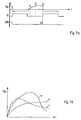
- FIG. 7a shows a time diagram of the course of the voltage U VL1 present at the connection VL1, the switching state of the inverter switch T3 and the switching state of the switch S206 shown in FIG. 6. Furthermore, the individual sampling times T 1 , T 2 and T 3 are indicated in FIG. 7a.
- the evaluation of the comparison result provided by the comparator 202 between the samples at the times T 1 and T 2 or T 1 and T 3 takes place in the measuring phase controller 900.
- the transient process that is to say on the basis of the sample values at the times T 1 - T 3 formed voltage characteristic
- 7b shows an example of the characteristic curve of the voltage signal U VL1 present at the connection VL1 for three different cases.
- the characteristic curve a corresponds to the characteristic curve which arises when the upper gas discharge lamp G1 shown in FIG. 1 changes.
- the characteristic curve b corresponds to the characteristic curve when changing the lower gas discharge lamp G2 during the lamp change detection operation.
- the third characteristic curve c shown in FIG. 7b corresponds to the characteristic curve in normal operation without changing the lamp, ie in the event that all lamps are connected.
- the control circuit IC2 is in when a lamp fault occurs the transient behavior with regard to the occurrence of the characteristic curves Monitor a or b. As soon as the voltage at the connection VL1 according to a of these characteristics, it means that one of the connected Gas discharge lamps have been removed from their version for troubleshooting.
- the control circuit IC2 or sequence control 800 then goes into the actual one Lamp change detection state in which, as in the fault state, only the lower inverter switch T3 is opened and closed with 40Hz, for example, while the upper inverter switch T2 is permanently open. In this condition the control circuit IC2 waits for the appearance of the characteristic curve c, d. H. that instead of the removed lamp a replacement lamp has been used and now all Lamps are reconnected. The system then carries out a new or Restart through. This process will be described again later with reference to FIG. 9 explained.
- FIGS. 8a and 8b show two variants of the circuit 300 shown in FIG Detection of a warm / cold start operation. Both variants have in common that always voltage potential present at connection NP of the control circuit is evaluated and it is determined by comparison with a predetermined reference voltage Vref12 whether a warm or cold start is to be carried out. This comparison is made with the help a comparator 301 performed, the positive measurement input with the connection NP connected is. On the output side, the comparator 301 is connected to a state hold circuit 302 connected, which can be implemented for example by a D flip-flop. This State hold circuit 302 causes the output of comparator 301 only if there is a corresponding EN release signal for sequence control 800 is switched through and evaluated.
- This enable signal EN takes only when restarting or restarting the entire system, for example by Activation of a corresponding mains switch, briefly a high level. To at no later time does a signal change at the NP connection lead to a State change at the output terminal of the state hold circuit 302.
- a switch can be made between a cold start and a warm start operation. If the series resistor R v is connected to VDD, a cold start operation is activated, ie the connected gas discharge lamps are ignited without preheating operation. On the other hand, if the series resistor R v is connected to the ground potential, a warm start operation is carried out, ie the connected gas discharge lamps are ignited with an upstream preheating operation for preheating the lamp electrodes.
- the comparator 301 can determine whether the resistor R V is connected to the supply voltage potential VDD or the ground potential by monitoring the voltage potential at the connection NP. The evaluation of the comparator output signal finally takes place in the sequence control 800 shown in FIG. 3, which, depending on whether a cold start or warm start mode is selected, controls the gas discharge lamps without or with preheating operating states.
- FIG. 8b shows a variant of the circuit explained above, which has a dynamic Switching between a warm and cold start mode enabled.
- the in Fig. 8b The circuit shown corresponds essentially to the circuit shown in FIG. 8a, however with the exception that a switch S301. is internally connected to the input terminal NP is provided, via which the supply voltage potential VDD to the Input connector NP can be applied while external to connector NP RC element consisting of the resistor R22 and already shown in FIGS. 1 and 2 Capacitor C17 is connected.
- the comparator 301 the voltage potential present at the input terminal NP supervised.
- the function of the circuit shown in Fig. 8b is as follows.
- the switch is S301 closed, so that the capacitor C17 through the connected to the input terminal NP applied supply voltage potential VDD is charged. Does it happen (e.g. as a result of an error) to switch off the system or to switch the system supply from mains to emergency power operation, switch S301 is opened and the capacitor C17 discharges with the time constant defined by the RC element. Is in accordance with the norm the RC element advantageously designed such that the capacitor C17 the charge can hold as long that the voltage applied to the input connection NP for a Duration of up to 400 ms longer than that applied to comparator 301 Reference voltage Vref12 is.
- the enable signal EN takes State hold circuit 302 goes high so that the comparison result of the Comparator 301 is turned on. Is that at that time Input terminal NP applied voltage potential is even greater than that Reference voltage Vref12, the sequence control 800 ensures the commissioning of the connected gas discharge lamps without preheating operation and thus leads one Cold start through. On the other hand, is that applied to the input connection NP Voltage potential less than the reference potential Vref12, the connected Gas discharge lamps preheated and a warm start carried out.
- the Control circuit applied voltage potential depending on the duty cycle of the Switch S301 is synonymous with the operating time of the electronic Ballast is.
- This size is decisive for the state of charge of the Capacitor C17.
- the voltage potential at the input terminal is NP on the switch-off time of switch S301 or the duration of the emergency power operation of the electronic ballast and the time constant of the RC element. This Values are decisive for the discharge process of the capacitor C17.
- the circuit shown in Fig. 8b thus leads depending on the duration of the switch-off time as well as a cold or warm start depending on the time constant of the RC element.
- the one Switch-off duration can be set that is just for a cold start operation connected lamps is sufficient.
- the RC element only has to do so dimensioned that after charging the capacitor C17 and opening the Switch S301 the voltage potential applied to the input terminal NP straight even after the aforementioned switch-off period has elapsed, it is greater than the reference potential Vref12 of the comparator 301.
- the maximum permitted time is standard between switching to emergency power mode and restarting or restarting the electronic ballast without preheating the lamp electrodes to 400 ms established. Accordingly, the resistor R22 and the capacitor C17 are such dimension that the previously mentioned time period of 400 ms are observed can.
- any other energy storage circuit are used, which are dependent on that applied to the input terminal NP Supply voltage potential stores energy and deals with a certain Time constant discharges after disconnection of the supply voltage potential.
- This Energy storage circuit can thus contain any delay elements, as long as a defined and known temporal behavior of the delay element or Energy storage circuit is given.
- the function blocks 400 and 500 shown in FIG. 3 will be explained in more detail below become.
- the voltage regulator function block 400 generates an internally regulated, very precise supply voltage VDD for all internal function blocks that are also the Represents source for all required reference voltages. As can be seen from FIGS. 1 and 2 is this internal supply voltage VDD via the connection VDD to the outside placed and over the external capacitor C7 mt good radio frequency characteristics filtered. Due to the provision of the internal supply voltage VDD for all functional parts of the entire electronic ballast one Low voltage level can be used, which is particularly advantageous for cost reasons.
- the reference voltage generator 500 serves to generate all of them centrally Reference quantities for the control circuit IC2, i.e. to generate all reference potentials and reference currents.
- the oscillator 600 shown in FIG. 3 is the central clock source for the whole Control circuit IC2.
- the oscillator 600 is designed such that no external Components are required.
- the basic clock of the oscillator is with the help of micro fuses to the desired value of, for example, 10 MHz with an accuracy of z. B. 4-bit matched.
- Via a digital input of the oscillator 600 Frequency of the clock generator to approx. 1/20 of the nominal clock rate, i.e. to about 550kHz, be reduced. This reduced clock rate is described in more detail below is, for certain operating conditions, in particular for the error and Lamp change detection state needed, in which the supply energy is reduced must become.
- the time base generator 700 also shown in FIG.
- the sequencer function block 800 receives for example all time reference quantities from the time base generator 700. All Time quantities generated by the time base generator 700 are a multiple of the Basic clock of the oscillator 600. The generated by the time base generator 700 The individual preheating times or the Include ignition time. These temporal reference values are as follows in more detail is explained, in particular for the temporal operating state control of the Control circuit IC2 of importance by the sequencer function block 800 is carried out.
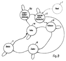
- sequence controller 800 The function of the sequence controller 800 is described in more detail below with reference to FIG. 9 are explained.
- Flow control function block 800 controls the operation of the electronic Ballast, for example, according to the state diagram shown in FIG. 9. 9, each possible operating state is represented by a circle, while the individual arrows represent possible changes of state, which under Fulfillment of a condition associated with the two operating states occur. These conditions are specific to certain states or to certain states Monitoring quantities of the electronic ballast or the lamp (s) linked, these monitoring variables internally in the form of the sequence control 800 are processed by variables which depend on whether the monitoring variable is the appropriate state or not, for example the value "1" when ingested of the assigned state or "0" if the state is not taken.
- the Individual variables monitored by the sequence controller 800 can, for example include time-based variables or error variables.
- the expiry of a commissioning time, a Preheat time, an ignition time or a delay time for the Rectification effect detection can be monitored.
- the error sizes can for example the occurrence of a capacitive current in the load circuit (via the Current detection block 100), the presence of an overvoltage on the connected Gas discharge lamp, the occurrence of a rectification effect or one unbalanced lamp operation, the absence of a lamp or that Occurrence of a synchronization error regarding the zero crossing of the Lamp voltage (each via the voltage detection block 200) are monitored.
- the output signal of the function block 300 can be monitored with whose help is differentiated between a warm and a cold start operation can.
- any other monitoring parameters of the electronic ballast conceivable.
- the individual error quantities are affected by the blocks 100-300 shown in FIG. 3, but first one takes place Processing by the measurement phase control function block 900 before the individual Error quantities are actually evaluated by the sequence control 800.
- To this Purpose contains the measurement phase control for each monitored error size digital event filter assigned to the corresponding error size.
- This digital In principle, event filters perform the function of a counter, which is the continuous occurrence of the corresponding error counts. An error message will appear only then from the corresponding event filter to the sequencer 800 passed on if the corresponding error has occurred n times in succession, where n corresponds to the filter depth of the corresponding digital event filter and for each Error size can be different.
- a filter depth of 64 for the detection of a capacitive current a filter depth of 64, for the detection of an overvoltage a filter depth of 3 and for the detection of a synchronization error as well as for the lamp change detection a filter depth of 7 each can be provided.
- Filter depth values there are others too Filter depth values conceivable.
- the initial state of the operating state control shown in FIG. 9 is the so-called. Reset state (state I).
- the system is in state I whenever the electronic ballast has been started or restarted what synonymous with the occurrence of the enable signal EN explained with reference to FIG. 8 is.
- the sequencer 800 may have a hysteresis Comparator include the external supply voltage signal VCC inside certain limits are monitored and the enable signal EN is generated, if that Supply voltage signal VC within the required Supply voltage range is.
- the comparator monitors in this way at the same time switching the entire system on and off.
- the enable signal EN can thus asynchronous to all depending on switching the entire system on and off other signals occur, whereby after the release signal EN, i.e.
- the sequence control 800 automatically goes into operation a commissioning state (state II).
- state II a commissioning state
- the transition from state I to state II is exceptionally not linked to certain conditions and is done automatically each time the electronic ballast is restarted or restarted.
- state II the harmonic filter starts up or the load circuit of the electronic ballast.
- the coupling capacitor is in state II of the load circuit preloaded. In this phase, all error detectors are deactivated, i.e. there is no evaluation of the error sizes mentioned above.
- a preheating condition III is started from condition II, e.g. a State II assigned commissioning time, which is the normal operating time of the State II denotes, has expired and from the functional block shown in Fig. 3 300 no cold start operation has been reported. However, the commissioning time is still not expired, the system remains in state II, which is shown in FIG. 9 one starting from state II and returning to state II Arrow is shown.
- a cold start operation detected by function block 300 and if the commissioning time has already expired the sequence control 800 changes directly from state II to an ignition state IV, which was explained above Warm start operation corresponds.
- the inverter half bridge is activated in such a way that that it vibrates at the upper limit in frequency and, for example, a Output frequency of approximately 80 kHz is generated.
- the preheating control, overvoltage detection and capacitive current detection must be activated.
- the operating frequency of the electronic inverter Ballast depending on the value of the lamp current detected and the States of overvoltage and capacitive current detection can be changed.
- the control variable "lamp current" First reduce the output frequency of the inverter, since the detected Lamp current because of the not yet ignited compared to the given Setpoint is clearly too small.
- This control process continues until the Overvoltage detection or capacitive current detection the continuous reduction of the Inverter frequency prevented or counteracts this.
- Overvoltage detection should first become dominant as an influencing factor. As a result of The dominance of overvoltage detection that now exists is now, as it were Lamp voltage regulated.
- the ignition state IV can be in the direction of the previously mentioned operating state V only be exited after the specified ignition time. This change of state is in particular regardless of whether in ignition state IV is still related to the ignition voltage or is already regulated based on the lamp current.
- the output frequency of the inverter depends on the lamp current detected.
- This operating state V is the overvoltage, capacitive current and Synchronization error detection activated, even during this state Control circuit only every other period of the inverter output frequency carries out a new setpoint / actual value comparison.
- the rectification effect detection can likewise (GLRE) must be activated.
- the operating state V is not limited in time, i.e. represents in Principle is an endless loop, and can only be activated if one of the activated error detectors are exited.
- all error detectors of the control circuit activated.
- the fault state VII shown in FIG. 9 has started.
- This error condition is VII thus the central point of contact for all serious operational disruptions.
- the Fault state VII is jumped directly from preheating state III, if overvoltage or capacitive current operation during these preheat conditions has been recorded.
- the fault condition VII is based on the Operating state V started if capacitive current operation during this state, an overvoltage error, a synchronization error and / or the occurrence of a Rectification effect, etc. detected with respect to the connected gas discharge lamps has been.
- fault state VII can, for example, occur simultaneously with a appropriate signaling of the respective error for the user.
- Error state VII is only exited by the sequential control system if after a Restart the system again via reset state I, commissioning state II started and the gas discharge lamps are put into operation again.
- the fault state VII can be left if it is detected in this state is that not all lamps connected to the electronic ballast have intact lamp filaments. This is equivalent to the fact that the Fault condition VII in the direction of that already mentioned Lamp change detection status VIII is exited as soon as one of the connected gas discharge lamps is removed from their socket.
- the Operating current consumption of the control circuit reduced to a minimum possible value is.
- the electronic ballast as in Lamp change detection state operated, d. H. it will be the bottom one Inverter switch T3 opened with a low frequency of, for example, 40 Hz and closed while the upper inverter switch is permanently open.
- the control circuit IC2 waits in Fault condition VII on the occurrence of the voltage characteristic curves a or b (see FIG. 7a) on Voltage measurement connection VL1, which is the removal of one of the connected Corresponds to gas discharge lamps G1, G2. In this case, the control circuit IC2 goes in the lamp change detection state VIII.
- the Control circuit both a change or a removal of the top Gas discharge lamp G1 and the lower gas discharge lamp G2 (see FIG. 1) Detect reliably and automatically recognize one after detecting a lamp change Restart the system. While it is checked in error state VII whether a of the gas discharge lamps has been removed in the Lamp change detection status VIII monitors whether all gas discharge lamps are used. Once it has been recognized that all gas discharge lamps are used have been, i.e. all connected to the electronic ballast Lamp filaments are intact, will automatically return to commissioning state II switched and the gas discharge lamps again according to that shown in Fig. 9 Functional circuit put into operation. Even during the Lamp change detection status VIII are with the exception of Lamp change detection deactivated all other fault detectors.
- the inverter control function block 1000 is used to generate Control signals for the upper and lower inverter switches T2, T3 (see Fig. 1), which are output via the output connections OUTH or OUTL of the control circuit become. Depending on these control signals, the two inverter switches either turned on or open. As a rule, the inverter control generates 1000 alternating control pulses for the control connections OUTH or OUTL of the two inverter switches T2 and T3 and can also have an internal Have dead time counter function to ensure a sufficient dead time between the control of the two inverter switches. In the lamp change detection state VIII (see FIG.
- the inverter control 1000 ensures that the upper Output connection OUTH the upper inverter switch T2 remains permanently open, while only the lower inverter switch T3 with a relatively low Frequency alternately opened via the lower output connection OUTL and is closed.
- the inverter control 1000 ensures in particular an asymmetrical Duty cycle of the inverter switch, however, this asymmetry with a Output frequency of the inverter of, for example, 43 kHz only 2.1% and at an output frequency of 80kHz is only 4% and therefore hardly significant falls.
- the generation of unbalanced output signals for the two Inverter switch leads to an increase in the frequency resolution of the Inverter, i.e. with the help of the control circuit, smaller frequency steps of the Inverter can be set.
Abstract
Description
Die vorliegende Erfindung betrifft ein elektronisches Vorschaltgerät zum Betreiben
mindestens einer Leuchtstoff- oder Gasentladungslampe nach dem Oberbegriff des
Anspruches 1.The present invention relates to an electronic ballast for operation
at least one fluorescent or gas discharge lamp according to the preamble of
Ein derartiges elektronisches Vorschaltgerät ist beispielsweise aus der EP-B1-0338 109 bekannt. Fig. 10 zeigt den prinzipiellen Aufbau dieses elektronischen Vorschaltgerätes.Such an electronic ballast is for example from EP-B1-0338 109 known. Fig. 10 shows the basic structure of this electronic ballast.
Das in Fig. 10 gezeigte elektronische Vorschaltgerät umfaßt zunächst eine Schaltung A, welche an das Wechselstromnetz angeschlossen ist. Diese Schaltung A dient als HF-Oberwellenfilter zur Reduzierung der harmonischen Oberwellen der Netzfrequenz sowie zur Funkentstörung.The electronic ballast shown in FIG. 10 first comprises a circuit A, which is connected to the AC network. This circuit A serves as an RF harmonic filter to reduce the harmonic harmonics of the mains frequency as well for radio interference suppression.
An die Schaltung A schließt sich eine Gleichrichterschaltung B an, die die Netzspannung in eine gleichgerichtete Zwischenspannung umwandelt und diese über ein Oberwellenfilter C, welches zur Glättung der Zwischenspannung dient, einer Wechselrichterschaltung D zuführt. Dieser Wechselrichter D dient quasi als steuerbare Wechselspannungsquelle und wandelt die Gleichspannung des Gleichrichters B in eine variable Wechselspannung um. Der Wechselrichter D umfaßt in der Regel zwei (nicht dargestellte) steuerbare Schalter, beispielsweise MOS-Feldeffekttransistoren. Die beiden Schalter sind in Form einer Halbbrückenschaltung verschaltet und werden mit Hilfe eines entsprechenden Brückentreibers alternierend derart angesteuert, daß jeweils einer der Schalter ein- und der andere ausgeschaltet ist. Die beiden Wechselrichterschalter sind dabei in Serienschaltung zwischen eine Versorgungsspannung und Masse angeschlossen, wobei am gemeinsamen Knotenpunkt zwischen den beiden Wechselrichterschaltern ein Lastkreis bzw. Ausgangskreis E angeschlossen ist, in dem eine Gasentladungslampe oder Leuchtstofflampe G angeordnet ist. Dieser Ausgangskreis E umfaßt einen Serienresonanzkreis, über den die "zerhackte" hochfrequente Wechselspannung des Wechselrichters D der Leuchtstofflampe G zugeführt wird.The circuit A is followed by a rectifier circuit B which supplies the mains voltage converted into a rectified intermediate voltage and this via a harmonic filter C, which serves to smooth the intermediate voltage, an inverter circuit D supplies. This inverter D serves as a controllable AC voltage source and converts the DC voltage of the rectifier B into a variable AC voltage. The inverter D generally comprises two controllable switches (not shown), for example MOS field effect transistors. The two switches are in the form of a Half-bridge circuit interconnected and are using an appropriate Bridge driver alternately controlled such that one of the switches on and one other is off. The two inverter switches are connected in series connected between a supply voltage and ground, being at the common Node between the two inverter switches a load circuit or Output circuit E is connected in which a gas discharge lamp or Fluorescent lamp G is arranged. This output circuit E includes one Series resonance circuit via which the "chopped" high-frequency AC voltage of the Inverter D of the fluorescent lamp G is supplied.
Vor dem Anlegen der Zündspannung an die Leuchtstofflampe G werden die Lampenelektroden der Leuchtstofflampe G vorgeheizt, um die Lebensdauer der Lampe zu verlängern. Das Vorheizen kann beispielsweise mit Hilfe eines Heiztransformators erfolgen, dessen Primärwicklung mit dem Serienresonanzkreis verbunden ist, während die Sekundärwicklungen des Heiztransformators mit den einzelnen Lampenwendeln gekoppelt sind. Auf diese Weise ist es möglich, auch im gezündeten Betrieb die Lampenwendeln mit Energie zu versorgen. Im Vorheizbetrieb wird die Frequenz der von dem Wechselrichter D gelieferte Wechselspannung gegenüber der Resonanzfrequenz des Serienresonanzkreises des Ausgangskreises E derart verändert, daß die an der Gasentladungslampe G anliegende Spannung keine Zündung der Lampe verursacht. In diesem Fall fließt durch die als Wendeln ausgeführte Lampenelektroden der Lampe ein im wesentlichen konstanter Strom, wodurch die Lampenwendeln vorgeheizt werden. Nach Ablauf der Vorheizphase wird die Frequenz der von dem Wechselrichter D gelieferten Wechselspannung in die Nähe der Resonanzfrequenz des Serienresonanzkreises verschoben, wodurch sich die an der Gasentladungslampe G anliegende Spannung erhöht, so daß die Gasentladungslampe G gezündet wird.Before the ignition voltage is applied to the fluorescent lamp G, the Lamp electrodes of the fluorescent lamp G preheated to increase the lamp life extend. The preheating can, for example, with the help of a heating transformer take place, the primary winding is connected to the series resonance circuit, while the Secondary windings of the heating transformer coupled to the individual lamp filaments are. In this way it is possible to use the lamp filaments even in the ignited mode To supply energy. In preheating mode, the frequency of the inverter D supplied AC voltage compared to the resonance frequency of the series resonance circuit of the output circuit E changed such that the applied to the gas discharge lamp G. Voltage does not cause the lamp to ignite. In this case, flows through the as Lamp electrodes of the lamp which are made in the form of a spiral have an essentially constant current, whereby the lamp filaments are preheated. After the preheating phase, the Frequency of the AC voltage supplied by the inverter D in the vicinity of Resonance frequency of the series resonance circuit shifted, which changes the Gas discharge lamp G applied voltage increases, so that the gas discharge lamp G is ignited.
Während des Vorheizens, Zündens und Betriebs der Gasentladungslampe G können bestimmte Fehlerfälle auftreten, die es zu erkennen gilt, um entsprechend darauf reagieren zu können. Zu diesem Zweck weist das elektronische Vorschaltgerät eine Steuerschaltung F auf, die verschiedene Schaltungsgrößen des elektronischen Vorschaltgerätes überwacht und bei Überschreiten eines Grenzwertes ein entsprechendes Steuersignal für den Wechselrichter D erzeugt, um die Frequenz der von dem Wechselrichter D erzeugten Wechselspannung abhängig von dem detektierten Fehlerfall zu verändern. So kann beispielsweise die Steuerschaltung F die Lampenspannung, die Vorheizspannung, den Lampenbetriebsstrom, den Impedanz-Phasenwinkel des Ausgangskreises E oder die von dem Gleichrichter B erzeugte Gleichspannung überwachen und die Wechselrichterfrequenz derart einstellen, daß die Lampenspannung, die Vorheizspannung bzw. der Lampenstrom einen vorgegebenen Grenzwert nicht überschreiten, die dem Gleichrichter B entnommene Gleichstromleistung möglichst konstant ist oder ein kapazitiver Betrieb des Serienresonanz-Ausgangskreises E vermieden wird.During the preheating, ignition and operation of the gas discharge lamp G. certain errors occur that need to be identified in order to react accordingly to be able to. For this purpose, the electronic ballast has a control circuit F on, which monitors various circuit sizes of the electronic ballast and if a limit value is exceeded, a corresponding control signal for the Inverter D generates the frequency of those generated by the inverter D. AC voltage to change depending on the detected fault. So can for example, the control circuit F, the lamp voltage, the preheating voltage Lamp operating current, the impedance phase angle of the output circuit E or that of Monitor the DC voltage generated by the rectifier B and the inverter frequency adjust so that the lamp voltage, the preheating voltage or the lamp current do not exceed a predetermined limit value that was taken from the rectifier B. DC power is as constant as possible or a capacitive operation of the series resonance output circuit E is avoided.
Wie zuvor beschrieben worden ist, ist es bekannt, mit Hilfe eines Vorheizbetriebs die Lampenwendeln der Gasentladungslampe vorzuheizen, um deren Lebensdauer zu verlängern. Dies führt jedoch dazu, daß infolge des Vorheizbetriebs eine längere Zeitspanne vergeht, bis die Gasentladungslampe gezündet und in Betrieb genommen werden kann. Es sind jedoch Fälle denkbar, bei denen auf das Vorheizen der Lampenelektroden verzichtet werden kann, beispielsweise wenn die entsprechende Gasentladungslampe kurz zuvor bereits betrieben worden ist. As described above, it is known to use a preheating operation Preheat the lamp filaments of the gas discharge lamp to increase their lifespan extend. However, this leads to a longer one due to the preheating operation Time elapses before the gas discharge lamp is ignited and put into operation can be. However, there are cases in which the preheating of the Lamp electrodes can be omitted, for example if the corresponding one Gas discharge lamp has previously been operated.
Ein einfaches Verfahren zum Wählen eines geeigneten Lampenstarts ist in der GB 2 053 592 A beschrieben. Diese offenbart ein elektronisches Vorschaltgerät für eine Gasentladungslampe, bei dem die an einem Kondensator anliegende Spannung, die von dem Widerstand und damit von der Temperatur der Wendeln abhängig ist, überwacht wird. Je nachdem, ob der Widerstand einen vorgegeben Grenzwert über- oder unterschreitet, ob also die Wendeltemperatur oberhalb oder unterhalb einer Schwellentemperatur liegt, wird die Lampe ohne bzw. mit Vorheizung gestartet. Fällt beispielsweise die Stromversorgung nur kurzfristig aus, so daß sich die Wendeln lediglich geringfügig abgekühlt haben, kann nach Wiederherstellung der Stromversorgung die Lampe ohne Zeitverzögerung wiedergestartet werden.A simple procedure for choosing a suitable lamp start is in the GB 2 053 592 A. This discloses an electronic ballast for one Gas discharge lamp, in which the voltage applied to a capacitor, that of the resistance and thus the temperature of the filaments is monitored becomes. Depending on whether the resistance exceeds a predetermined limit or falls below whether the coil temperature is above or below one Threshold temperature, the lamp is started with or without preheating. falls for example, the power supply only for a short time, so that the coils have cooled down only slightly, after restoration of the Power supply to the lamp can be restarted without any time delay.
Eine anderes Verfahren ist in der WO 95/10168 beschrieben. Dabei wird zu Beginn des Lampenbetriebs ein Kondensator aufgeladen und die Zündung der Lampe eingeleitet, sobald die an dem Kondensator anliegende Spannung einen bestimmten Schwellwert erreicht hat. Wird die Lampe vorübergehend ausgeschaltet, entlädt sich der Kondensator wieder zu einem gewissen Grad, so daß bei einem erneuten Lampenstart die Vorheizdauer von der Menge der auf dem Kondensator verbliebenen Ladung abhängt.Another method is described in WO 95/10168. At the beginning of the A capacitor charged and the lamp started, as soon as the voltage across the capacitor reaches a certain threshold has reached. If the lamp is switched off temporarily, the capacitor will discharge again to a certain extent, so that when the lamp is started again Preheating time depends on the amount of charge remaining on the capacitor.
Der vorliegenden Erfindung liegt die Aufgabe zugrunde, die aus dem Stand der Technik bekannten Verfahren zur Auswahl der Art des Lampenstarts zu verbessern und gleichzeitig eine zuverlässige Funktionsweise zu gewährleisten.The present invention is based on the object of the prior art improve known methods for selecting the type of lamp start and to ensure reliable functioning at the same time.
Diese Aufgabe wird durch ein elektronisches Vorschaltgerät mit den Merkmalen des
Anspruches 1 gelöst. Die Unteransprüche beschreiben vorteilhafte und bevorzugte
Ausführungsbeispiele der vorliegenden Erfindung.This task is performed by an electronic ballast with the characteristics of
Das elektronische Vorschaltgerät weist eine Steuerschaltung auf, die eine Schaltungs- bzw. Betriebsgröße des elektronischen Vorschaltgerätes überwacht und abhängig von dem Wert dieser Schaltungsgröße das elektronische Vorschaltgerät entweder mit einem Vorheizbetrieb oder ohne einen Vorheizbetrieb betreibt. Das elektronische Vorschaltgerät ist dabei derart ausgestaltet, daß es automatisch bei einem Neu- oder Wiederstart erkennt, ob die entsprechend angesteuerte Gasentladungslampe zuvor bereits in Betrieb war, so daß ggf. auf ein Vorheizen der Lampenelektroden der Gasentladungslampe verzichtet werden kann.The electronic ballast has a control circuit which or operating size of the electronic ballast is monitored and dependent on the value of this circuit size, the electronic ballast either with a Operates preheating or without preheating. The electronic Ballast is designed such that it automatically when a new or Restart detects whether the correspondingly controlled gas discharge lamp previously was already in operation, so that the lamp electrodes may need to be preheated Gas discharge lamp can be dispensed with.
Dies erfolgt mit Hilfe einer Energiespeicherschaltung, die während des Betriebs des elektronischen Vorschaltgeräts aufgeladen und nach Abschalten mit einer bestimmten Zeitkonstante entladen wird. Die Steuerschaltung erfaßt beim Neustarten des elektronischen Vorschaltgeräts automatisch eine der in der Energiespeicherschaltung verbliebenen Ladung entsprechende Spannung - wobei diese ein Maß für die Ausschaltzeit des elektronischen Vorschaltgerätes ist - und vergleicht sie mit Hilfe von Komparatormitteln mit einem Referenzwert. Ist die zum Wiedereinschaltzeitpunkt des elektronischen Vorschaltgeräts noch verbliebene Ladung ausreichend hoch, steuert die Steuerschaltung die Gasentladungslampe ohne Vorheizbetrieb an. Andernfalls wird ein Vorheizbetrieb durchgeführt.This is done with the help of an energy storage circuit, which during the operation of the electronic ballast and charged after switching off with a certain Time constant is discharged. The control circuit detects when the electronic ballast automatically one of those in the energy storage circuit remaining charge corresponding voltage - this being a measure of the The electronic ballast is switched off - and compares it with the help of Comparator means with a reference value. Is the at the time of restart of the electronic ballast still high enough charge controls the Control circuit on the gas discharge lamp without preheating. Otherwise, a Preheating operation carried out.
Erfindungsgemäß wird die Energiespeicherschaltung, die beispielsweise durch ein an die Steuerschaltung angeschlossenes RC-Glied gebildet sein kann, während des Betriebs auf ein vorgegebenes (festes) Versorgungsspannungspotential aufgeladen. Darüber hinaus ist das Ergebnis des Vergleichs zwischen der an dem Kondensator verbliebenen Spannung und der Referenzspannung einer Zustandshalteschaltung zugeführt, welche das Ausgangssignal der Komparatormittel lediglich beim Starten des elektronischen Vorschaltgerätes an ihren Ausgang durchschaltet, wobei die Steuerschaltung das Ausgangssignal der Zustandshalteschaltung für die Inbetriebnahme der Gasentladungslampe auswertet.According to the invention, the energy storage circuit, for example by a the control circuit connected RC element can be formed during operation charged to a predetermined (fixed) supply voltage potential. About that in addition, the result of the comparison between that remaining on the capacitor Voltage and the reference voltage of a state hold circuit, which the output signal of the comparator means only when starting the electronic Ballast switches through to its output, the control circuit Output signal of the state hold circuit for the commissioning of the Evaluates gas discharge lamp.
Das erfindungsgemäße Verfahren bietet gegenüber den bekannten Verfahren mehrere Vorteile. Zum einen hat das Aufladen der Energiespeicherschaltung auf ein vorgegebenes und damit bekanntes Versorgungsspannungspotential zur Folge, daß das zeitliche Verhalten der überwachten Schaltungsgröße vollständig bekannt und von äußeren Einflüssen sowie von evtl. Dimmeinstellungen der Lampe zum Zeitpunkt des Abschaltens des Vorschaltgeräts unabhängig ist. Mit der Kenntnis des zeitlichen Verhaltens ist es allerdings möglich, die Schaltung derart auszulegen, daß nach einer bestimmten vorgegebenen Ausschaltzeit die Lampe unabhängig von der zu diesem Zeitpunkt vorliegenden Wendeltemperatur auf jeden Fall mit Vorheizbetrieb gestartet wird. Somit ist beispielsweise auch die Möglichkeit gegeben, eine entsprechende Norm, die nach einer Abschaltdauer von mehr als 400 ms in jedem Fall einen Lampenstart mit Vorheizbetrieb fordert, zu erfüllen.The method according to the invention offers several compared to the known methods Benefits. For one, charging the energy storage circuit has a predetermined and thus known supply voltage potential as a result that temporal behavior of the monitored circuit size fully known and from external influences as well as possible dimming settings of the lamp at the time of the Switching off the ballast is independent. With the knowledge of the temporal Behavior, however, it is possible to design the circuit so that after a certain predetermined switch-off time the lamp regardless of the to this In any case, the present coil temperature started with preheating mode becomes. Thus, for example, there is also the possibility of a corresponding standard, which always starts with a lamp after a switch-off period of more than 400 ms Preheat operation requires to be met.
Der zweite Vorteil der erfindungsgemäßen Schaltung besteht darin, daß sichergestellt ist, daß die Auswertung des Vergleichsergebnisses lediglich während des Lampenstarts durchgeführt wird, eine Veränderung des Ausgangssignals zu einem späteren Zeitpunkt allerdings keinen Einfluß auf den weiteren Betrieb hat. The second advantage of the circuit according to the invention is that it ensures is that the evaluation of the comparison result only during the lamp start a change in the output signal is carried out at a later time however, it has no influence on further operations.
Mit Hilfe der erfindungsgemäßen Lösung kann sichergestellt werden, daß die Gasentladungslampe möglichst rasch in Betrieb genommen werden kann, indem auf einen nicht erforderlichen Vorheizbetrieb verzichtet wird. Durch diese Maßnahme werden zugleich die Lampenelektroden der Gasentladungslampe geschont, da ein übermäßiges Erhitzen der Lampenelektroden ebenfalls verhindert wird. Dabei ist sichergestellt, daß auch bei Inbetriebnahme der Gasentladungslampe ohne Vorheizbetrieb eine ausreichende Temperatur der Lampenelektroden zum Zünden der Gasentladungslampe vorhanden ist.With the help of the solution according to the invention it can be ensured that the Gas discharge lamp can be put into operation as quickly as possible by clicking on one unnecessary preheating mode is dispensed with. Through this measure At the same time, the lamp electrodes of the gas discharge lamp are protected because they are excessive Heating of the lamp electrodes is also prevented. This ensures that sufficient even when the gas discharge lamp is started up without preheating Temperature of the lamp electrodes for igniting the gas discharge lamp is present.
Die Erfindung wird nachfolgend anhand bevorzugter Ausführungsbeispiele unter
Bezugnahme auf die beigefügte Zeichnung näher erläutert.
Das in Fig. 1 gezeigte elektronische Vorschaltgerät umfaßt zunächst eine Schaltung A, welche eingangsseitig an eine Versorgungsspannung, beispielsweise eine Netzspannung, angeschlossen wird und zur Funkentstörung dient. Die Schaltung A ist in üblicher Weise aufgebaut und umfaßt beispielsweise kapazitive Eingangsfilter sowie ggfs. Oberwellendrosseln. In Fig. 1 sind lediglich beispielhaft ein Kondensator C2 sowie ein Symmetrieübertrager L1 dargestellt, wobei ein Überspannungsableiter oder ein VDR mit der Bezeichnung F1 parallel geschaltet sein kann.The electronic ballast shown in FIG. 1 first comprises a circuit A, which on the input side to a supply voltage, for example a mains voltage, is connected and used for radio interference suppression. Circuit A is in the usual way constructed and includes, for example, capacitive input filters and possibly. Harmonic chokes. In Fig. 1, a capacitor C2 and a are only exemplary Symmetry transformer L1 shown, with a surge arrester or a VDR with the designation F1 can be connected in parallel.
Die sich an die Schaltung A anschließende Schaltung B umfaßt eine Vollwellengleichrichterbrücke mit Dioden V1 - V4. Die Gleichrichterschaltung B wandelt die eingangsseitig anliegende Versorgungswechselspannung in eine gleichgerichtete Zwischenspannung um. Die Gleichrichterschaltung B kann demnach entfallen, falls das elektronische Vorschaltgerät mit Gleichspannung betrieben wird.The circuit B following the circuit A comprises one Full wave rectifier bridge with diodes V1 - V4. The rectifier circuit B converts the supply AC voltage present on the input side into a rectified one Intermediate voltage around. The rectifier circuit B can therefore be omitted if that electronic ballast is operated with DC voltage.
Der nachfolgende Schaltungsteil C dient zur Oberwellenfilterung und Glättung der von dem Gleichrichter B gelieferten Zwischenspannung. Die in Fig. 1 gezeigte Schaltung C umfaßt beispielsweise Kondensatoren C3, C11, eine Diode V5, eine Spule L2, einen MOS-Feldeffekttransistor T1 und eine als integrierte Schaltung ausgestaltete Steuerschaltung IC1. Die Steuerschaltung IC1 ist an ein Versorgungsspannungspotential VCC angeschlossen und kann mit den übrigen Schaltungselementen derart verschaltet sein, daß sie verschiedene Spannungspotentiale U oder Ströme I empfängt. Der in Fig. 1 gezeigte Aufbau der Schaltung C ist selbstverständlich rein beispielhaft zu verstehen.The following circuit part C is used for harmonic filtering and smoothing of the intermediate voltage supplied to the rectifier B. The circuit C shown in Fig. 1 includes, for example, capacitors C3, C11, a diode V5, a coil L2, one MOS field-effect transistor T1 and an integrated circuit Control circuit IC1. The control circuit IC1 is at a supply voltage potential VCC connected and can be connected to the other circuit elements in such a way that it receives different voltage potentials U or currents I. The one in Fig. 1 The structure of the circuit C shown is of course to be understood purely as an example.
Von dem in Fig. 1 gezeigten Oberwellenfilter C wird eine Wechselrichterschaltung D angesteuert, die als wesentliche Elemente zwei in Serie zwischen eine Versorgungsspannungsleitung und Masse geschaltete steuerbare Schalter, im vorliegenden Beispiel in Form von MOS-Feldeffekttransistoren T2 und T3, aufweist. Die beiden Wechselrichterschalter T2, T3 sind zu einer Halbbrücke verschaltet und werden jeweils mit Hilfe einer als integrierte Schaltung ausgebildeten Steuerschaltung IC2 angesteuert, d.h. geöffnet und geschlossen. Die Steuerschaltung IC2 übernimmt somit zugleich die Funktion eines Brückentreibers und ist an eine entsprechende Versorgungsspannungsleitung VCC angeschlossen bzw. mit dieser gekoppelt. Die Wechselrichterschaltung D erzeugt abhängig von der von der Gleichrichterschaltung B erzeugten gleichgerichteten Zwischenspannung eine Wechselspannung mit variabler Frequenz und/oder Tastverhältnis. Allgemein ist der Wechselrichter D in üblicher Weise aufgebaut und seine Funktion ist hinreichend bekannt, so daß hier auf eine weitere Erläuterung verzichtet werden kann. Von Bedeutung ist an dieser Stelle lediglich, daß die Steuerschaltung IC2 abhängig von ihr zugeführten Steuersignalen die beiden Wechselrichterschalter T2 und T3 alternierend ansteuert, so daß am Verbindungspunkt zwischen den beiden Wechselrichterschaltern T2 und T3 eine "zerhackte", hochfrequente Wechselspannung auftritt.From the harmonic filter C shown in FIG. 1, an inverter circuit D controlled as the essential elements two in series between one Supply voltage line and ground switched controllable switches, in the present Example in the form of MOS field effect transistors T2 and T3. The two Inverter switches T2, T3 are connected to form a half bridge and are each controlled with the aid of a control circuit IC2 designed as an integrated circuit, i.e. opened and closed. The control circuit IC2 thus also takes over Function of a bridge driver and is connected to a corresponding one Supply voltage line VCC connected or coupled to it. The Inverter circuit D generates depending on that of rectifier circuit B. generated rectified intermediate voltage an AC voltage with variable Frequency and / or duty cycle. In general, the inverter D is in the usual way built and its function is well known, so here on another Explanation can be omitted. It is only important at this point that the Control circuit IC2 the two depending on the control signals supplied Inverters T2 and T3 control alternately, so that at the connection point a "chopped", high-frequency between the two inverter switches T2 and T3 AC voltage occurs.
Mit dem Wechselrichter D ist ein Serienresonanz-Ausgangskreis bzw. Lastkreis E verbunden. Im vorliegenden Fall ist der Lastkreis E für den Anschluß von zwei Gasentladungslampen G1, G2 in Tandemkonfiguration ausgelegt. Selbstverständlich läßt sich der Lastkreis E auch dahingehend abwandeln, daß lediglich eine Gasentladungslampe oder mehr als zwei Gasentladungslampen betrieben werden können. Aus Fig. 1 ist ersichtlich, daß der Lastkreis E einen Serienresonanzkreis bestehend aus einer Resonanzkreisspule L3 und einem Resonanzkreiskondensator C14 aufweist. Dieser Serienresonanzkreis bzw. die Resonanzkreisspule L3 ist an den Verbindungspunkt zwischen den beiden Wechselrichterschaltern T2 und T3 angeschlossen und der Resonanzkreiskondensator C14 ist derart angeordnet, daß er parallel zu der zu betreibenden Gasentladungslampe bzw. den zu betreibenden Gasentladungslampen G1, G2 geschaltet ist. Die von dem Wechselrichter D erzeugte hochfrequente Wechselspannung wird über den Serienresonanzkreis den Gasentladungslampen G1 und G2 zugeführt.With the inverter D is a series resonance output circuit or load circuit E. connected. In the present case, the load circuit E is for the connection of two Gas discharge lamps G1, G2 designed in tandem configuration. Of course leaves load circuit E also change in such a way that only one gas discharge lamp or more than two gas discharge lamps can be operated. From Fig. 1 can be seen that the load circuit E is a series resonance circuit consisting of a Has resonant circuit coil L3 and a resonant circuit capacitor C14. This Series resonance circuit or resonance circuit coil L3 is at the connection point connected between the two inverter switches T2 and T3 and the Resonant circuit capacitor C14 is arranged to be parallel to that operating gas discharge lamp or the gas discharge lamps G1, G2 to be operated is switched. The high-frequency AC voltage generated by the inverter D. is supplied to the gas discharge lamps G1 and G2 via the series resonance circuit.
Wie bereits erläutert worden ist, sind gemäß dem in Fig. 1 gezeigten Beispiel die beiden Gasentladungslampen G1 und G2 in Tandemkonfiguration an den Lastkreis E bzw. das elektronische Vorschaltgerät angeschlossen. Dies bedeutet, daß - wie aus Fig. 1 ersichtlich ist - die obere Wendel der oberen Gasentladungslampe G1 sowie die untere Wendel der unteren Gasentladungslampe G2 direkt an den Lastkreis E angeschlossen sind, während die untere Wendel der oberen Gasentladungslampe G1 und die obere Wendel der unteren Gasentladungslampe G2 miteinander verbunden und an den Lastkreis E angeschlossen sind. Vor dem Anlegen der Zündspannung an die Gasentladungslampen G1, G2 werden diese vorgeheizt, um die Lebensdauer der Gasentladungslampen zu verlängern. Zu diesem Zweck ist gemäß Fig. 1 ein Heizübertrager L4 vorgesehen, dessen Primärwicklung in Serie mit dem Resonanzkreiskondensator C14 geschaltet ist, während die Sekundärwicklung die untere Wendel der oberen Gasentladungslampe G1 und die obere Wendel der unteren Gasentladungslampe G2 miteinander verbindet. Im Vorheizbetrieb wird die Frequenz der von dem Wechselrichter E gelieferten Wechselspannung bezüglich der Resonanzfrequenz des Serienresonanzkreises derart eingestellt, daß die über dem Resonanzkreiskondensator C14 und damit über den Gasentladungslampen G1 und G2 anliegende Spannung keine Zündung der Gasentladungslampen hervorruft. In diesem Fall fließt durch die Wendeln der Gasentladungslampen G1, G2 ein im wesentlichen konstanter Vorheizstrom. Der in Fig. 1 dargestellte Kondensator C15 bewirkt eine Anpassung der Vorheizspannung bei der in Fig. 1 dargestellten Tandemkonfiguration der Gasentladungslampen G1 und G2. Das zuvor erläuterte Prinzip des Vorheizens kann selbstverständlich auf einfache Art und Weise auch auf den Betrieb von einer Gasentladungslampe oder mehr als zwei Gasentladungslampen übertragen werden. Des weiteren ist abgesehen von der Tandemkonfiguration auch eine Parallelkonfiguration bzw. Parallelschaltung mehrerer Gasentladungslampen G1, G2 denkbar. In Fig. 1 ist jedoch die Tandemkonfiguration der Gasentladungslampen G1, G2 dargestellt, da bei einer derartigen Lampenkonfiguration mit Hilfe des in Fig. 1 dargestellten elektronischen Vorschaltgerätes vorteilhaft auf einfache Art und Weise ein Lampenwechsel sowohl der oberen als auch der unteren Gasentladungslampe festgestellt werden kann. Die Lampenwechselerkennung wird nachfolgend noch näher erläutert. Zum Zweck der Lampenwechselerkennung dient u.a. auch der in Fig. 1 dargestellte Widerstand R12.As has already been explained, according to the example shown in FIG. 1, the two are Gas discharge lamps G1 and G2 in tandem configuration to the load circuit E or that electronic ballast connected. This means that - as can be seen from Fig. 1 is - the upper filament of the upper gas discharge lamp G1 and the lower filament of the lower gas discharge lamp G2 are connected directly to the load circuit E, while the lower filament of the upper gas discharge lamp G1 and the upper filament of the lower Gas discharge lamp G2 connected to each other and connected to the load circuit E. are. Before applying the ignition voltage to the gas discharge lamps G1, G2 these are preheated to extend the life of the gas discharge lamps. To this 1, a heat exchanger L4 is provided whose primary winding is in Series is connected to the resonant circuit capacitor C14, while the Secondary winding, the lower filament of the upper gas discharge lamp G1 and the upper one Helix of the lower gas discharge lamp G2 connects. In preheating mode becomes the frequency of the AC voltage supplied by the inverter E. the resonance frequency of the series resonance circuit set such that the above Resonant circuit capacitor C14 and thus across the gas discharge lamps G1 and G2 applied voltage does not cause ignition of the gas discharge lamps. In this case flows through the filaments of the gas discharge lamps G1, G2 a substantially constant Preheating. The capacitor C15 shown in FIG. 1 adapts the Preheating voltage in the tandem configuration shown in Fig. 1 Gas discharge lamps G1 and G2. The principle of preheating explained above can of course in a simple way also on the operation of one Gas discharge lamp or more than two gas discharge lamps are transmitted. Of apart from the tandem configuration, a parallel configuration or Parallel connection of several gas discharge lamps G1, G2 possible. In Fig. 1, however, is Tandem configuration of the gas discharge lamps G1, G2 shown, since such Lamp configuration using the electronic ballast shown in Fig. 1 Advantageously, a lamp change of both the upper and the lower gas discharge lamp can be determined. The lamp change detection is explained in more detail below. For the purpose of lamp change detection, also the resistor R12 shown in FIG. 1.
Nach Ablauf der Vorheizphase wird über die Steuerschaltung IC2 die Frequenz der von dem Wechselrichter D gelieferten Wechselspannung in die Nähe der Resonanzfrequenz des Serienresonanzkreises verschoben, wodurch die an den Resonanzkreiskondensator C14 und den Gasentladungslampen G1, G2 anliegende Spannung erhöht wird, wodurch diese Gasentladungslampen zünden.After the preheating phase, the frequency of the the AC voltage supplied to the inverter D in the vicinity of the resonance frequency of Series resonant circuit shifted, which leads to the resonant circuit capacitor C14 and the voltage applied to the gas discharge lamps G1, G2 is increased, as a result of which this Ignite gas discharge lamps.
Nach Zünden der Gasentladungslampen geht das in Fig. 1 dargestellte elektronische Vorschaltgerät in die eigentliche Betriebsphase über, in der die Frequenz der von dem Wechselrichter D gelieferten Wechselspannung beispielsweise kontinuierlich derart eingestellt wird, daß durch die Gasentladungslampen G1, G2 ein möglichst konstanter Lampenstrom fließt oder an den Gasentladungslampen eine möglichst konstante Lampenspannung anliegt. Wie noch nachfolgend näher erläutert wird, weist das in Fig. 1 gezeigte elektronische Vorschaltgerät eine Reihe von Fehlerdetektoren auf, die bestimmte Schaltungsgrößen des elektronischen Vorschaltgerätes, insbesondere des Lastkreises E, überwachen und bei Erfassen eines bestimmten Fehlers eine entsprechende Ansteuerung des Wechselrichters D herbeiführen, um beispielsweise das Auftreten einer Überspannung an den Gasentladungslampen G2 und G2, eines Gleichrichteffekts in den Gasentladungslampen G1, G2 oder eines kapazitiven Betriebs des Lastkreises E zu vermeiden. After igniting the gas discharge lamps, the electronic shown in Fig. 1 goes Ballast in the actual operating phase, in which the frequency of the Inverter D supplied AC voltage continuously, for example is set that a constant as possible by the gas discharge lamps G1, G2 Lamp current flows or a constant as possible on the gas discharge lamps Lamp voltage is present. As will be explained in more detail below, this is shown in FIG. 1 Electronic ballast shown on a number of fault detectors that determined Circuit sizes of the electronic ballast, in particular the load circuit E, monitor and when a certain error is detected, a corresponding control of the inverter D to cause, for example, the occurrence of an overvoltage on the gas discharge lamps G2 and G2, a rectifying effect in the Gas discharge lamps G1, G2 or a capacitive operation of the load circuit E. avoid.
Zur Steuerung des Wechselrichters D dient ein Schaltungsmodul, welches als Herzstück die bereits zuvor erwähnte Steuerschaltung IC2 sowie mehrere externe Komponenten als externe Beschaltung der Steuerschaltung IC2 umfaßt. Die wesentlichen externen Komponenten sind sechs Widerstände R10, R13 - R16 und R21, R22 sowie zwei Kondensatoren C7 und C17. Wie in Fig. 1 gezeigt ist, sind die einzelnen externen Komponenten an jeweilige Eingangsanschlüsse der Steuerschaltung IC2 angeschlossen. Die mit der Steuerschaltung IC2 verbundenen externen Komponenten dienen primär zur Erfassung bestimmter Schaltungsgrößen des elektronischen Vorschaltgerätes, so daß diese in der Steuerschaltung IC2 ausgewertet werden können.To control the inverter D, a circuit module serves as the heart the previously mentioned control circuit IC2 and several external components as external circuitry of the control circuit IC2 comprises. The main external Components are six resistors R10, R13 - R16 and R21, R22 and two Capacitors C7 and C17. As shown in Fig. 1, the individual are external Components connected to respective input connections of the control circuit IC2. The External components connected to the control circuit IC2 serve primarily for Detection of certain circuit sizes of the electronic ballast, so that this can be evaluated in the control circuit IC2.
Fig. 2 zeigt eine vergrößerte Darstellung der in Fig. 1 dargestellten Steuerschaltung IC2 sowie die externe Beschaltung der einzelnen Eingangsanschlüsse der Steuerschaltung IC2. Dabei sind in Fig. 2 lediglich die wesentlichen Anschlüsse und externen Bauelemente dargestellt. Im vorliegenden Beispiel ist die Steuerschaltung IC2 vorteilhafterweise als anwendungsspezifische integrierte Schaltung (Application Specific Integrated Circuit, ASIC) ausgebildet und in einem mehrpoligen SMD-Gehäuse (Surface Mounted Device) untergebracht. Im vorliegenden Fall ist die Steuerschaltung IC2 sowohl für den Betrieb eines einzelnen Lampenausgangskreises E als auch für den Betrieb eines für eine in Fig. 1 gezeigte Tandemkonfiguration mit mehreren Gasentladungslampen ausgelegten Lastkreises E geeignet.FIG. 2 shows an enlarged illustration of the control circuit IC2 shown in FIG. 1 as well as the external wiring of the individual input connections of the control circuit IC2. 2 are only the essential connections and external components shown. In the present example, the control circuit IC2 is advantageously as application specific integrated circuit, ASIC) and in a multi-pole SMD housing (Surface Mounted Device) accommodated. In the present case, the control circuit IC2 is both for operation of an individual lamp output circuit E and also for the operation of one for one in FIG. 1 Tandem configuration shown with several gas discharge lamps designed load circuit E suitable.
Wie bereits erwähnt worden ist und insbesondere aus Fig. 2 ersichtlich ist, besitzt die Steuerschaltung IC2 mehrere Anschlüsse, die folgende Funktionen aufweisen. An den Anschluß GND ist das Bezugspotential, d.h. das Massepotential, für die einzelnen Analogund Digitalfunktionsblöcke der Steuerschaltung IC2 angelegt. Aus Fig. 1 ist ersichtlich, daß das Massepotential des gesamten elektronischen Vorschaltgerätes über einen Koppelkondensator C1 geerdet ist. An dem Anschluß VDD, der über den Koppelkondensator C7 mit dem Massepotential verbunden ist (vgl. Fig. 1), wird die intern generierte Versorgungsspannung für die einzelnen Analog- und Digtalfunktionsblöcke der Steuerschaltung IC2 bereitgestellt. Der Anschluß NP dient, wie noch näher nachfolgend erläutert wird, zur externen Einstellung sowie Erkennung der Vorheizmethode, d.h. zur Auswahl zwischen einem Kaltstart- und Warmstartbetrieb. Insbesondere ist der Anschluß NP extern derart beschaltet, daß eine dynamische Wahl der Vorheizmethode möglich ist. Der Anschluß VL1 erfaßt über die in Fig. 1 und teilweise in Fig. 2 dargestellten Widerstände R10 sowie R14, R15 die heruntergeteilte Lampenspannung der Gasentladungslampen G1, G2 und dient somit vornehmlich zur Lampenspannungsüberwachung. Analog dient der Anschluß ILC mit Hilfe der in Fig. 1 und teilweise in Fig. 2 gezeigten Widerstände R13 und R16 zur Überwachung des Ausgangskreis- bzw. Lastkreisstromes (Drosselstromes) bzw. zur Überwachung des durch die Gasentladungslampen G1, G2 nach deren Zünden fließenden Lampenstromes, indem mit Hilfe des Shunt-Widerstandes R16 eine dazu proportionale Spannung erfaßt und der Steuerschaltung über den Anschluß ILC zugeführt wird. Der Anschluß VL1 dient somit zur Spannungsüberwachung, während der Anschluß ILC zur Stromüberwachung dient. Die beiden Ausgangsanschlüsse OUTL und OUTH dienen zur Ansteuerung des in Fig. 1 gezeigten tiefliegenden bzw. hochliegenden Halbbrückenschalters T3 bzw. T2. Zu diesem Zweck werden an den Ausgangsanschlüssen OUTL und OUTH Ansteuersignale (TTL-Pegel) zum Ein- bzw. Ausschalten der beiden Wechselrichterschalter T2 bzw. T3 bereitgestellt. Der Anschluß VCC der Steuerschaltung IC2 ist schließlich der zentrale Versorgungsspannungsanschluß der Steuerschaltung IC2.As has already been mentioned and can be seen in particular from FIG. 2, the Control circuit IC2 several connections, which have the following functions. To the Connection GND is the reference potential, i.e. the ground potential, for the individual analog and Digital function blocks of the control circuit IC2 created. 1 shows that the ground potential of the entire electronic ballast over a Coupling capacitor C1 is grounded. At the connection VDD, which over the Coupling capacitor C7 is connected to the ground potential (see. Fig. 1), the internal generated supply voltage for the individual analog and digital function blocks of the Control circuit IC2 provided. The NP connection serves, as will be explained in more detail below for external setting and detection of the preheating method, i.e. to Selection between a cold start and warm start operation. In particular, the connection NP connected externally in such a way that a dynamic choice of the preheating method is possible. The connection VL1 is detected via those shown in FIG. 1 and partly in FIG. 2 Resistors R10 and R14, R15 divided the lamp voltage of the Gas discharge lamps G1, G2 and thus primarily serves Lamp voltage monitoring. The connection ILC is used analogously with the aid of FIG. 1 and resistors R13 and R16 shown partially in Fig. 2 for monitoring the Output circuit or load circuit current (choke current) or for monitoring the through the gas discharge lamps G1, G2 after their ignition flowing lamp current by with the help of the shunt resistor R16 a voltage proportional thereto and the Control circuit is supplied via the connection ILC. The connection VL1 thus serves for voltage monitoring, while the ILC connection is used for current monitoring. The Both output connections OUTL and OUTH serve to control the one in FIG. 1 shown low or high half-bridge switch T3 or T2. To this Purpose are control signals (TTL level) at the output connections OUTL and OUTH for switching the two inverter switches T2 and T3 on and off provided. The connection VCC of the control circuit IC2 is finally the central one Supply voltage connection of the control circuit IC2.
Der Versorgungsspannungsbereich kann beispielsweise 10-18V umfassen. Des weiteren steuert die Steuerschaltung IC2 die Wechselrichterschalter T2 und T3 derart an, daß von der Wechselrichterschaltung D ausgangsseitig eine Wechselspannung variabler Frequenz mit einem Betriebsfrequenzbereich von beispielsweise 40-80kHz erzeugt wird.The supply voltage range can include 10-18V, for example. Furthermore controls the control circuit IC2, the inverter switches T2 and T3 such that from the inverter circuit D an AC voltage of variable frequency on the output side is generated with an operating frequency range of 40-80 kHz, for example.
Die Steuerschaltung IC2 bildet das Herzstück des gesamten in Fig. 1 dargestellten elektronischen Vorschaltgerätes und umfaßt demnach eine Vielzahl unterschiedlicher Funktionen. So kann beispielsweise mit Hilfe der Steuerschaltung IC2 die Vorheizmethode für die angeschlossene(n) Gasentladungslampe(n) dynamisch festgelegt und zwischen einem Kaltstart- und einem Warmstartbetrieb gewechselt werden. Zu diesem Zweck sorgt die Steuerschaltung IC2 für einen definierten Vorheizbetrieb mit einer definierten Vorheizzeit und einem definierten Vorheizstrom. Ebenso sorgt die Steuerschaltung IC2 für einen vordefinierten Zündbetrieb mit einer festgelegten Zündzeit und einer festgelegten Zündspannung. Über die Anschlüsse ILC bzw. VL1 der Steuerschaltung IC2 kann beispielsweise der Vorheizstrom und der Lampenbetriebsstrom bzw. die Lampenspannung erfaßt und auf einen möglichst konstanten Wert geregelt werden. Des weiteren wird von der Steuerschaltung IC2 über den Stromanschluß ILC ein kapazitiver Betrieb des Lastkreises E überwacht. Über den Spannungsanschluß VL1 kann zudem das Auftreten eines Gleichlichteffekts in einer angeschlossenen Gasentladungslampe G1, G2 erkannt werden. Ebenso kann mit Hilfe des Spannungsanschlusses VL1 das Auftreten eines Gasdefekts, welcher zu einer Überspannung an der entsprechenden Gasentladungslampe führt, erkannt und entsprechend das elektronische Vorschaltgerät in diesem Fall abgeschaltet werden. Eine besondere Funktion der Steuerschaltung IC2 ist das Erkennen eines Lampenwechsels, wobei bei der in Fig. 1 dargestellten Tandemkonfiguration die Lampenwechselerkennung insbesondere unabhängig von der gewechselten Lampe ist, d.h. es kann sowohl ein Wechsel der oberen Gasentladungslampe G1 als auch der unteren Gasentladungslampe G2 erkannt werden. Schließlich ist in der Steuerschaltung IC2 eine (vorzugsweise digital implementierte) Ablaufsteuerung realisiert, die dafür sorgt, daß die an das elektronische Vorschaltgerät angeschlossene(n) Gasentladungslampe(n) gemäß vorbestimmten Betriebszuständen angesteuert werden, wobei von einem Betriebszustand in einen neuen Betriebszustand nur bei Erfüllung mindestens einer bestimmten Bedingung gewechselt werden kann. Innerhalb eines jeden Betriebszustandes ist eine betriebszustandsabhängige Überwachung bestimmter Größen des elektronischen Vorschaltgerätes möglich, so daß abhängig von dem jeweiligen Betriebszustand unterschiedliche Fehlergrößen überwacht und unterschiedlich ausgewertet werden können. Hinsichtlich der Fehler erfolgt insbesondere eine ereignisgefilterte Fehlerbewertung, d.h. mit Hilfe beispielsweise digitaler Ereignisfilter wird sichergestellt, daß auf das Vorliegen eines Fehlers nur dann geschlossen wird, falls der entsprechende Fehler tatsächlich mehrmals hintereinander auftritt.The control circuit IC2 forms the heart of the whole shown in FIG. 1 electronic ballast and therefore includes a variety of different Functions. For example, using the control circuit IC2, the preheating method for the connected gas discharge lamp (s) dynamically defined and between a cold start and a warm start operation can be changed. For this purpose the control circuit IC2 for a defined preheating operation with a defined one Preheating time and a defined preheating current. The control circuit IC2 also ensures a predefined ignition operation with a specified ignition time and a specified Ignition voltage. The connections ILC or VL1 of the control circuit IC2 can for example the preheating current and the lamp operating current or the lamp voltage recorded and regulated to a constant value as possible. Furthermore, from the control circuit IC2 a capacitive operation of the Load circuit E monitors. The occurrence can also occur via the voltage connection VL1 of a constant light effect in a connected gas discharge lamp G1, G2 recognized become. Likewise, the occurrence of a Gas defect, which leads to an overvoltage on the corresponding gas discharge lamp leads, recognized and accordingly the electronic ballast in this case be switched off. A special function of the control circuit IC2 is recognition a lamp change, the. In the tandem configuration shown in FIG Lamp change detection is in particular independent of the changed lamp, i.e. both the upper gas discharge lamp G1 and the lower one can be changed Gas discharge lamp G2 can be detected. Finally, there is one in the control circuit IC2 (preferably digitally implemented) sequence control implemented, which ensures that the gas discharge lamp (s) connected to the electronic ballast in accordance with predetermined operating states are controlled, with an operating state in a new operating state only if at least one specific condition is met can be changed. There is one within each operating state Condition-dependent monitoring of certain sizes of the electronic Ballast possible, so that depending on the respective operating state Different error sizes can be monitored and evaluated differently. With regard to the errors, an event-filtered error evaluation takes place, i.e. with the help of digital event filters, for example, it is ensured that the presence of an error is only closed if the corresponding error actually occurs occurs several times in a row.
Neben den zuvor kurz zusammengefaßten Funktionen besitzt die Steuerschaltung IC2 weitere Funktionen, die allesamt nachfolgend unter Bezugnahme auf die beigefügte Zeichnung näher erläutert werden sollen.In addition to the functions briefly summarized above, the control circuit has IC2 other functions, all of which are given below with reference to the attached Drawing to be explained in more detail.
Fig. 3 zeigt ein Blockschaltbild des internen Aufbaus der zuvor beschriebenen
Steuerschaltung IC2. Mit dem Stromanschluß ILC ist zunächst ein Modul 100 gekoppelt,
welches u.a. zur zuvor erläuterten Stromerfassung sowie Kapazitivstromerfassung des
Lastkreises dient. Die Auswertung des über den Anschluß ILC erfaßten Stroms erfolgt
insbesondere mit Hilfe eines durch eine Komparatorschaltung gebildeten Reglers. Um den
Schaltungsaufwand wirklich gering zu halten, wird dieser Komparatorschaltung auch das
von dem Spannungsanschluß VL1 der Steuerschaltung IC2 empfangene und von einem
Modul 200 aufbereitete Spannungssignal zugeführt und ausgewertet. Das Modul 200 dient
insbesondere zur Erfassung der Lampenspannung, zur Gleichrichteffekterkennung sowie
zur Lampenwechselerkennung. Des weiteren ist mit dem Anschluß NP ein weiteres Modul
300 gekoppelt, welches zur Erkennung des Warm- oder Kaltstartbetriebes beim Vorheizen
der anzusteuernden Gasentladungslampe(n) sowie zur Realisierung eines dynamischen
Vorheizbetriebs dient. Mit den Versorgungsspannungsanschlüssen VCC und VDD ist ein
Spannungsreglermodul 400 verbunden, welches einen internen Spannungsregler aufweist,
der eine geregelte, sehr präzise Spannung zur Spannungsversorgung sämtlicher interner
Funktionsblöcke bereitstellt. Ein weiteres Modul 500 dient als Quelle für sämtliche
benötigte Referenzgrößen, d.h. Referenzspannungen und Referenzströme, in der
Steuerschaltung IC2. Ein Oszillator 600 dient als interner Taktgeber der Steuerschaltung
IC2, wobei ein damit gekoppelter Zeitbasisgenerator 700 abhängig von dem vorgegebenen
Takt des Oszillators 600 interne zeitliche Größen für die Ablaufsteuerung der
Steuerschaltung IC2, wie z.B. die Vorheiz- oder Zündzeit, ableitet. Ein weiteres Modul
800 dient zur Realisierung der Ablaufsteuerung der einzelnen Betriebszustände des
gesamten elektronischen Vorschaltgerätes und wirkt eng mit einem weiteren Modul 900,
welches zur Meßphasensteuerung dient, zusammen. Das Modul 900 dient insbesondere zur
ereignisgefilterten Auswertung bestimmter Fehlergrößen des elektronischen
Vorschaltgerätes sowie zur meßphasenabhängigen Ansteuerung sämtlicher Schalter der
einzelnen Funktionsblöcke der Steuerschaltung IC2. Die Ablaufsteuerung 800 wertet die
ereignisgefilterten Zustandsmeldungen der Meßphasensteuerung 900 aus und steuert
abhängig von den von dem Zeitbasisgenerator 700 vorgegebenen zeitlichen Größen die
einzelnen Betriebszustände des elektronischen Vorschaltgerätes bzw. der Steuerschaltung
IC2. Schließlich weist die Steuerschaltung IC2 ein weiteres Modul 1000 zur
Wechselrichteransteuerung auf. Mit Hilfe dieses Moduls 1000 werden von der
Meßphasensteuerung 900 gelieferte Frequenzeinstellungssignale in entsprechende
Steuersignale für den oberen Wechselrichterschalter (über den Ausgangsanschluß OUTH)
bzw. den unteren Wechselrichterschalter (über den Ausgangsanschluß OUTL) umgesetzt.Fig. 3 shows a block diagram of the internal structure of the previously described
Control circuit IC2. A
Die Steuerschaltung IC2 kann sowohl analog als auch digital implementierte
Funktionsblöcke umfassen. Im vorliegenden Fall umfaßt der Digitalteil der als ASIC
ausgebildeten Steuerschaltung IC2 den Zeitbasisgenerator 700, die Ablaufsteuerung 800,
die Meßphasensteuerung 900 sowie die Wechselrichteransteuerung 1000. Insbesondere
kann die Steuerschaltung IC2 derart ausgestattet sein, daß der Digitalteil bezüglich des
Flächenbedarfs der Steuerschaltung IC2 dem Analogteil entspricht.The control circuit IC2 can be implemented both analog and digital
Function blocks include. In the present case, the digital part comprises the ASIC
trained control circuit IC2, the
Fig. 4 zeigt ein detailliertes Schaltbild des in Fig. 3 dargestellten Stromerfassungsmoduls 100. In Fig. 4 sind auch die extern mit dem Stromanschluß ILC der Steuerschaltung verbundenen Widerstände R13 und R16 dargestellt, die auch in Fig. 1 gezeigt sind.FIG. 4 shows a detailed circuit diagram of the current detection module shown in FIG. 3 100. In Fig. 4 are also the external with the power connector ILC of the control circuit connected resistors R13 and R16, which are also shown in FIG. 1.
Intern wird dem am Stromanschluß ILC erfaßten Signal ein Bezugsstrom Iref1 aufaddiert,
um sicherzustellen, daß das von dem Stromerfassungsmodul 100 zu verarbeitende Signal
stets im Arbeitsspannungsbereich der Steuerschaltung liegt.Internally, a reference current Iref1 is added to the signal detected at the current connection ILC,
to ensure that the signal to be processed by the
Wie in Fig. 4 gezeigt ist, ist eine Integratorschaltung 105 vorgesehen, die zur Integration
des ihr zugeführten Eingangssignals dient. Der gesamte Funktionsblock 105 ist derart
realisiert, daß die Integratorfunktion sowohl zur Messung des Lampenstromes (über den
Anschluß ILC) im Normalbetrieb, als auch zur Gleichrichteffekterkennung (über den
Anschluß VL1) genutzt werden kann. As shown in Fig. 4, an
Die Integratorschaltung 105 kann Abtasthalteglieder aufweisen, welche abwechselnd jede
Periode des internen Taktgenerators (vgl. Modul 600 in Fig. 3) das Eingangssignal des
Integrators abtasten. Die dadurch in den Abtasthaltegliedern gespeicherte Ladung wird an
einen Integrationsverstärker der Integratorschaltung 105 weitergegeben. Dieser Vorgang
wird zyklisch wiederholt.The
Der Integrator 105 kann einen internen steuerbaren Schalter aufweisen, welcher die zuvor
erwähnten Abtasthalteglieder überbrückt und während der Dauer des Offsetabgleichs des
Integrators 105 geschlossen wird. Auf diese Weise kann ein beliebiges Signal,
insbesondere das am Eingangsanschluß ILC anliegende Signal über den Schalter S105 oder
ein Referenzspannungspotential zur Gleichrichteffekterkennung vom Spannungsblock 200
über den Schalter S107, während der Initialisierungsphase an den eigentlichen
Integrationsverstärker angelegt werden.The
Der eigentliche Integrationsverstärker des Integrators 105 hat die Aufgabe, das
Strommeßsignal am ILC-Anschluß zeitlich exakt gesteuert aufzuintegrieren. Für den Fall,
daß das am ILC-Anschluß anliegende Strommeßsignal von dem Integrationsverstärker der
Integratorschaltung 105 aufintegriert wird, ist der Schalter S105 geschlossen, während für
den Fall der Gleichrichteffektauswertung das über den Schalter S107 zugeführte
Referenzpotential für die Gleichrichteffektauswertung an der Integratorschaltung 105
anliegt.The actual integration amplifier of the
Als eigentlicher Regler dient schließlich ein Komparator 103, der den erforderlichen Soll-/Istwertvergleich
durchführt und an den Ausgang Integrators 105 angeschlossen ist. Durch
die in Fig. 4 gezeigte Anordnung dieses Komparators 103 ist es möglich, den Komparator
103 sehr flexibel einzusetzen. Durch entsprechende Betätigung eines Schalters S124
können an den Komparator 103 verschiedene Referenzspannungen bzw. Referenzwerte
hinzugeschaltet bzw. angelegt werden, wobei in Fig. 4 beispielhaft Referenzspannungen
Vref1 - Vref6 dargestellt sind. Das Bezugspotential Vref1 und Vref2 entspricht dabei
beispielsweise einer gewünschten Vorheizspannung während eines
Vorheizbetriebszustandes. Während des Vorheizbetriebes wird somit mit Hilfe des
steuerbaren Schalter S124 die Referenzspannung Vref1 bzw. Vref2 an den Komparator
103 angelegt, so daß das augenblicklich am ILC-Anschluß anliegende und nicht integrierte
Meßsignal mit dem jeweils angelegten Referenzwert Vref1 bzw. Vref2 verglichen wird.
Im Normalbetrieb entspricht beispielsweise das Bezugspotential Vref3 dem
Integrationsstartwert des Integrationsverstärkers des Integrators 105, so daß bei Anliegen
dieses Bezugspotentials Vref3 der Komparator 103 die tatsächliche Veränderung des
Integrationsergebnisses erfassen kann. Die Bezugspotentiale Vref4 bzw. Vref6 können
einem positiven bzw. negativen Grenzwert für die über den Schalter S107 zugeführte und
aufintegrierte Lampenspannung des Anschlusses VL1 entsprechen, um somit durch
Vergleich mit diesen beiden Grenzwerten bei Überschreitung des Integrationsergebnisses
in positiver oder negativer Richtung das Auftreten eines Gleichrichteffekts zuverlässig
erkennen zu können. Zu diesem Zweck wird auch das weitere Bezugspotential Vref5
verwendet, welches bei der Gleichrichteffekterkennung hinzugeschaltet wird und dem
Ausgangs- bzw. Startwert für die Integration der über den Schalter S107 zugeführten
Lampenspannung entspricht. Durch Berücksichtigung der durch die Bezugspotentiale
Vref3 bzw. Vref5 vorgegebenen Startwerte des Integrationsverstärkers des Integrators 105
kann somit mit Hilfe des Komparators 103 die tatsächlich relativ zu dem entsprechenden
Startwert vorliegende Veränderung der entsprechenden Integrationsgröße festgestellt
werden.Finally, a
Das Ausgangssignal des Komparators 103 wird der in Fig. 3 dargestellten
Meßphasensteuerung 900 zugeführt, die dieses auswertet und abhängig von der
augenblicklichen Meßphase unterschiedlich bewertet. So sorgt die Meßphasensteuerung
900 beispielsweise für eine entsprechende Anpassung der Ausgangsfrequenz des
Wechselrichters des elektronischen Vorschaltgerätes, falls das von dem Komparator 103
überwachte Strommeßsignal des Anschlusses ILC von dem vorgegebenen Sollwert Vref3
abweicht. Für den Fall der Gleichrichteffektauswertung erzeugt hingegen, wie nachfolgend
noch näher erläutert wird, die Meßphasensteuerung ein ereignisgefiltertes Signal, welches
angibt, ob ein Gleichrichteffekt in einer angeschlossenen Gasentladungslampe vorliegt oder
nicht. Dieses Signal wird von dem in Fig. 3 gezeigten Ablaufsteuerungsblock 800
ausgewertet und zur Betriebszustandssteuerung des gesamten elektronischen
Vorschaltgerätes verwendet.The output signal of the
Im vorliegenden Fall wird insbesondere vorgeschlagen, während des Vorheizbetriebes den Spitzenwert des Vorheizstromes IHZ zu regeln. Für den Normalbetrieb wird hingegen vorgeschlagen, den Mittelwert bzw. den Effektivwert des Lampenbetriebsstromes IL zu regeln.In the present case, it is proposed in particular to regulate the peak value of the preheating current I HZ during the preheating operation. For normal operation, however, it is proposed to regulate the mean value or the effective value of the lamp operating current I L.
Wie in Fig. 4 gezeigt ist, kann das am Anschluß ILC anliegende Meßsignal auch unter
Umgehung der Integratorschaltung 105 überwacht und ausgewertet werden, um z.B. einen
kapazitiven Betrieb des Lastkreises des elektronischen Vorschaltgerätes zu erfassen. Hierzu
kann ein Detektor zur Erfassung eines in dem Lastkreis fließenden kapazitiven Stromes
vorgesehen sein, der beispielsweise den Phasenwinkel des Lastkreises, d.h. den
Phasenunterschied zwischen der Lastkreisspannung und dem Lastkreisstrom, ermittelt
(Kapazitivstromerfassung). Auch das Ergebnis dieser Überwachung bzw. Auswertung
kann der Meßphasensteuerung 900 zugeführt werden.As shown in Fig. 4, the measurement signal present at the connection ILC can also be under
Bypassing the
Das Auftreten eines kapazitiven Stroms im Lastkreis soll nachfolgend unter Bezugnahme auf Fig. 5a und 5b näher erläutert werden.The occurrence of a capacitive current in the load circuit will be referred to below 5a and 5b are explained in more detail.
Fig. 5a zeigt eine vergrößerte Darstellung der wesentlichen Elemente des bereits in Fig. 1 dargestellten Wechselrichters D sowie des Lastkreises E. Der Einfachheit halber wird in Fig. 5a davon ausgegangen, daß an den Lastkreis lediglich eine Gasentladungslampe G1 angeschlossen ist. In Fig. 5a sind die beiden in Serie geschalteten Wechselrichterschalter T2 und T3 dargestellt. Wie bereits in Fig. 1 gezeigt ist, ist der Lastkreis mit seinem Serienresonanzkreis an dem Verbindungspunkt zwischen den beiden Wechselrichterschaltern T2 und T3 angeschlossen, d.h. die Resonanzkreisspule L3 ist mit dem Resonanzkreiskondensator C14 parallel zu den unteren Wechselrichterschalter T3 geschaltet. Der Resonanzkreiskondensator C14 ist zudem parallel zu der Gasentladungslampe G1 angeschlossen. Zu den einzelnen Wechselrichterschaltern T2 und T3 sind Freilaufdioden V11 bzw. V12 parallel geschaltet, die zum Schutz des jeweiligen Wechselrichterschalters dienen.FIG. 5 a shows an enlarged illustration of the essential elements of the one already in FIG. 1 shown inverter D and the load circuit E. For the sake of simplicity in Fig. 5a assumed that only one gas discharge lamp G1 connected. 5a shows the two inverter switches connected in series T2 and T3 shown. As already shown in Fig. 1, the load circuit with its Series resonant circuit at the connection point between the two Inverter switches T2 and T3 connected, i.e. the resonance circuit coil L3 is with the resonant circuit capacitor C14 in parallel with the lower inverter switch T3 connected. The resonant circuit capacitor C14 is also parallel to that Gas discharge lamp G1 connected. To the individual inverter switches T2 and T3 free-wheeling diodes V11 and V12 are connected in parallel to protect the respective Serve as an inverter switch.
In Fig. 5b sind einerseits die Einschaltzustände der beiden Wechselrichterschalter T2 und T3 sowie der Stromverlauf des über die Drossel L3 fließenden Stromes IL3 und der zeitliche Verlauf des am Verbindungspunkt zwischen den beiden Wechselrichterschaltern T2 und T3 auftretenden Spannungspotentials VL dargestellt. Zum Einschaltzeitpunkt des oberen bzw. unteren Wechselrichterschalters T2 bzw. T3 fließt ein Strom in der Freilaufdiode des einzuschaltenden Wechselrichterschalters und die Wechselrichterhalbbrücke schaltet den Resonanzlastkreis induktiv, d.h. die Spannung bzw. das Potential VL eilt dem Drosselstrom IL3 voraus. Im Gegensatz dazu steht das kapazitive Schalten der Resonanzlast des Resonanzlastkreises. In diesem Arbeitsbereich fließt ein Strom in der dem einzuschaltenden Wechselrichterschalter entgegengesetzten Freilaufdiode, wodurch eine hohe Sperrspannung an der vorwärtsstromführenden Freilaufdiode eines der beiden Wechselrichterschalter auftritt. Dies folgt wiederum zu sehr hohen Recovery-Strömen, wodurch in beiden Wechselrichterschaltern T2 und T3 hohe Schaltverluste auftreten.5b shows on the one hand the switch-on states of the two inverter switches T2 and T3 as well as the current profile of the current I L3 flowing through the choke L3 and the time profile of the voltage potential V L occurring at the connection point between the two inverter switches T2 and T3. At the time the upper or lower inverter switch T2 or T3 is switched on, a current flows in the freewheeling diode of the inverter switch to be switched on and the inverter half bridge switches the resonant load circuit inductively, ie the voltage or potential V L leads the choke current I L3 . In contrast to this is the capacitive switching of the resonance load of the resonance load circuit. In this working area, a current flows in the freewheeling diode opposite the inverter switch to be switched on, as a result of which a high reverse voltage occurs at the forward-current-carrying freewheeling diode of one of the two inverter switches. This in turn follows to very high recovery currents, which results in high switching losses in both inverter switches T2 and T3.
Fig. 5a zeigt den Verlauf der einzelnen Ströme I1 - I4, die während der in Fig. 5b dargestellten Zeitintervalle t1 - t4 im Falle eines induktiven bzw. kapazitiven Drosselstromes IL3 auftreten. FIG. 5a shows the course of the individual currents I 1 -I 4 that occur during the time intervals t 1 -t 4 shown in FIG. 5b in the case of an inductive or capacitive inductor current I L3 .
Das obengenannte Phänomen tritt insbesondere bei Lastkreisspannungen VL mit einer in der Nähe der Resonanzfrequenz des Serienresonanzkreises liegenden Ausgangsfrequenz auf, was inbesondere beim Zünden der Gasentladungslampe G1 der Fall ist, wobei zunächst ein induktiver Strom in dem Lastkreis fließt, der zu einer Erwärmung der Spule L3 führt. Aufgrund der Erwärmung der Spule L3 sinkt deren Induktivität, so daß plötzlich ein Übergang von dem induktiven Bereich in den fehlerhaften kapazitiven Bereich auftritt.The above-mentioned phenomenon occurs in particular at load circuit voltages V L with an output frequency close to the resonance frequency of the series resonance circuit, which is particularly the case when the gas discharge lamp G1 is ignited, with an inductive current initially flowing in the load circuit which leads to heating of the coil L3 leads. Due to the heating of the coil L3, its inductance decreases, so that a transition suddenly occurs from the inductive area to the faulty capacitive area.
Zur Erkennung des unerwünschten kapazitiven Betriebs des Lastkreises kann nunmehr die
die Höhe der über den Eingang ILC erfaßten Stromamplitude des Lastkreises überwacht
und mit einem fest vorgegebenen Referenzwert verglichen werden. Vorteilhafterweise
wird die Höhe der Stromamplitude jeweils zum Einschaltzeitpunkt des unteren
Wechselrichterschalters T3 erfaßt, da in diesem Fall die Polaritäten der zu erfassenden
Meßwerte günstig für die Verarbeitung innerhalb der als ASIC ausgebildeten
Steuerschaltung IC2 sind. Liegt der erfaßte Stromwert unterhalb des durch das
entsprechende Referenzpotential vorgegebenen Grenzwerts, wird auf das Vorliegen eines
kapazitiven Betriebs das Lastkreises geschlossen, und es kann ein Ausgangssignal mit
einem hohen Pegel erzeugt werden, welches von dem in Fig. 3 gezeigten
Meßphasensteuerungsblock 900 ausgewertet und schließlich von dem ebenfalls in Fig. 3
gezeigten Wechselrichteransteuerungsblock 1000 derart in Ansteuersignale für die beiden
Wechselrichterschalter T2 und T3 umgesetzt wird, daß diese mit einer erhöhten Frequenz
alternierend ein- und ausgeschaltet werden, um die Arbeitsfrequenz zu erhöhen und somit
dem kapazitiven Betrieb entgegenzuwirken.To detect the undesired capacitive operation of the load circuit, the
monitors the level of the current amplitude of the load circuit detected via the input ILC
and compared with a fixed reference value. advantageously,
the height of the current amplitude at the time the lower one is switched on
Inverter switch T3 detected, because in this case the polarities of the to be detected
Measured values favorable for processing within the ASIC
Control circuit IC2 are. If the detected current value is below that by the
corresponding reference potential predetermined limit value, is based on the presence of a
capacitive operation of the load circuit closed, and there can be an output signal with
are generated at a high level, which is shown in FIG
Measurement
Nachfolgend soll unter Bezugnahme auf Fig. 6 der Aufbau sowie die Funktion des bereits in Fig. 3 angedeuteten Spannungserfassungsblocks 200 näher erläutert werden, der die am Spannungsanschluß VL1 anliegenden Meßsignale auswertet bzw. aufbearbeitet.In the following, the structure and the function of the already with reference to FIG. 6 in Fig. 3 indicated voltage detection blocks 200 are explained, which on Voltage connection VL1 evaluates or processes applied measurement signals.
Fig. 6 zeigt dabei einerseits den internen Aufbau des Spannungserfassungsblocks 200
sowie die mit dem Anschluß VL1 des Spannungserfassungsblocks 200 gekoppelte externe
Beschaltung der Steuerschaltung. Insbesondere ist in Übereinstimmung mit Fig. 1 aus Fig.
6 ersichtlich, daß ein Vorwiderstand R10 einerseits mit dem Anschluß VL1 und
andererseits mit einem Spannungsteiler bestehend aus Widerständen R14 und R15
gekoppelt ist, wobei die beiden Spannungsteilerwiderstände R14 und R15 parallel zu der
Gasentladungslampe G1 bzw. zu den in Fig. 1 tandemartig verschalteten
Gasentladungslampen G1 und G2 geschaltet sind. Der Einfachheit halber wird in Fig. 6
davon ausgegangen, daß im Gegensatz zu Fig. 1 lediglich eine Gasentladungslampe G1
angesteuert wird, zu der zudem der Resonanzkreiskondensator C14 parallel geschaltet ist. 6 shows the internal structure of the
Die beiden Widerstände R14 und R15 haben die Aufgabe, die an der Gasentladungslampe G1 anliegende Spannung herunterzuteilen, so daß mit Hilfe des am Verbindungspunkt zwischen den Widerständen R14 und R15 angreifenden Widerstandes R10 ein für die Lampenspannung repräsentatives Meßsignal dem Spannungsanschluß VL1 des Spannungserfassungsblocks 200 zugeführt werden kann.The two resistors R14 and R15 have the task of acting on the gas discharge lamp G1 to divide the applied voltage so that with the help of the connection point between the resistors R14 and R15 attacking resistor R10 for the Lamp voltage representative measurement signal to the voltage terminal VL1 Voltage detection blocks 200 can be supplied.
Vorteilhafterweise sind die drei externen Widerstände R10, R14 und R15 veränderlich, so daß - analog zu dem Stromanschluß ILC (vgl. die Widerstände R13, R16) - über einen Anschluß der Steuerschaltung vollkommen unabhängig voneinander zu verschiedenen Zeitpunkten insgesamt drei verschiedene Regelgrößen des elektronischen Vorschaltgerätes mit Hilfe ein und desselben Reglers eingestellt bzw. gesteuert werden können. Durch Einstellen der Widerstandswerte der Widerstände R10, R14 und R15 können demnach abhängig von dem augenblicklich verwendeten Lampentyp bzw. dem augenblicklich verwendeten elektronischen Vorschaltgerätetyp die Sollwerte für die Regelung der drei unterschiedlichen Regelgrößen eingestellt bzw. vorgegeben werden. Im vorliegenden Fall können mit Hilfe der drei externen veränderlichen Widerstände R10, R14 und R15 die folgenden Größen des elektronischen Vorschaltgerätes eingestellt werden: die maximale Lampenspannung positiv/negativ, die Amplitude des Wechselspannungsanteils des Lampenspannungssignals sowie die Signalanhebung des Lampenspannungssignals zur Gleichrichteffektauswertung.The three external resistors R10, R14 and R15 are advantageously variable, see above that - analogous to the power connection ILC (cf. resistors R13, R16) - via one Connection of the control circuit completely different from each other A total of three different control variables of the electronic ballast at times can be set or controlled using the same controller. By Accordingly, setting the resistance values of the resistors R10, R14 and R15 can depending on the type of lamp currently being used or on the instant used electronic ballast the setpoints for the regulation of the three different control variables can be set or specified. In the present case can with the help of the three external variable resistors R10, R14 and R15 the following sizes of the electronic ballast can be set: the maximum Lamp voltage positive / negative, the amplitude of the AC voltage component of the Lamp voltage signal and the signal increase of the lamp voltage signal for Rectifying effect evaluation.
Wie Fig. 6 zu entnehmen ist, ist wiederum eine interne Referenzstromquelle vorgesehen, die das am Spannungsanschluß VL1 anliegende Meßsignal mit einem zusätzlichen internen Strom Iref2 beaufschlagt. Im Gegensatz zu dem in Fig. 4 dargestellten ILC-Anschluß wird jedoch in diesem Fall der Referenzstrom Iref2 mit Hilfe des steuerbaren Schalters S207 lediglich während der Auswertung des Gleichrichteffekts aktiviert, d.h. geschlossen. Sämtliche weitere mit dem VL1-Anschluß verbundenen Auswertungen beziehen sich auf das am Anschluß VL1 anliegende Signal ohne zusätzlichen Referenzstrom Iref2, d.h. ohne Gleichstromoffset. Dementsprechend werden während der Gleichrichteffektauswertung sämtliche anderen Detektoren am VL1-Anschluß deaktiviert, da sie ansonsten falsche Ergebnisse liefern würden.As can be seen in FIG. 6, an internal reference current source is again provided, which the measuring signal present at the voltage connection VL1 with an additional internal Current Iref2 applied. In contrast to the ILC connector shown in Fig. 4 however, in this case the reference current Iref2 using the controllable switch S207 only activated during the evaluation of the rectification effect, i.e. closed. All other evaluations connected to the VL1 connection refer to the signal present at connection VL1 without additional reference current Iref2, i.e. without DC offset. Accordingly, during the rectification effect evaluation all other detectors on the VL1 connection deactivated, otherwise they are wrong Would deliver results.
Durch das Hinzuschalten des Referenzstromes Iref2 wird wiederum das am Anschluß VL1 anliegende Signal angehoben. Analog zum Einspeisen des in Fig. 4 gezeigten Referenzstromes Iref1 am Stromanschluß ILC ist jedoch dies bei der Gleichrichteffektauswertung unschädlich, da - wie nachfolgend noch näher erläutert wird - die Gleichrichteffekterkennung durch Auswertung des Ausgangssignals der in Fig. 4 gezeigten Integratorschaltung durchgeführt wird, wobei infolge der Mittelung durch die Integratorschaltung der Gleichstromanteil Iref1 bzw. Iref2 eliminiert wird.By connecting the reference current Iref2 in turn that at the connection VL1 applied signal raised. Analogous to feeding the one shown in FIG. 4 Reference current Iref1 at the current connection ILC, however, is the case with Rectifier effect evaluation is harmless because - as will be explained in more detail below - the rectification effect detection by evaluating the output signal of FIG. 4 integrator circuit shown is performed, due to the averaging by the Integrator circuit the DC component Iref1 or Iref2 is eliminated.
Zunächst soll die Gleichrichteffekterkennung mit Hilfe der vorliegenden Steuerschaltung näher erläutert werden. Wie bei anderen Lampen auch, tritt bei Gasentladungslampen aufgrund von Abnutzungserscheinungen der Heizwendel am Lebensdauerende der Gasentladungslampen der Effekt auf, daß sich die Lampenelektroden mit der Zeit ungleichmäßig abnutzen, d.h. die Abtragung der Emissionsschichten auf den Lampenelektroden ist unterschiedlich. Aufgrund der unterschiedlichen Abnutzung der Lampenelektroden entstehen Unterschiede im Emissionsvermögen der beiden Lampenelektroden. Dies hat zur Folge, daß beim Betrieb der entsprechenden Gasentladungslampe von einer Lampenelektrode zur anderen ein höherer Strom fließt als umgekehrt. Der zeitliche Verlauf des Lampenstromes weist somit eine Überhöhung einer Halbwelle auf. Durch die unterschiedliche Abtragung der beiden Lampenelektroden entstehen somit Asymmetrien, die nicht nur zu einem stärkeren Lichtflimmern am Lebensdauerende der Gasentladungslampe führen, sondern sogar im Extremfall einen Betrieb der Gasentladungslampe nur während einer Halbwelle zulassen. In diesem Fall wirkt die Gasentladungslampe wie ein Gleichrichter, so daß der zuvor beschriebene Effekt als "Gleichrichteffekt" bezeichnet wird.First, the rectification effect detection with the help of the present control circuit are explained in more detail. As with other lamps, gas discharge lamps occur due to wear and tear on the heating coil at the end of its service life Gas discharge lamps have the effect that the lamp electrodes change over time wear unevenly, i.e. the removal of the emission layers on the Lamp electrodes are different. Due to the different wear of the Lamp electrodes produce differences in the emissivity of the two Lamp electrodes. This has the consequence that when operating the corresponding Gas discharge lamp from one lamp electrode to another a higher current flows than vice versa. The course of the lamp current over time thus shows an excessive increase Half wave on. Due to the different removal of the two lamp electrodes This creates asymmetries that not only cause a stronger flicker of light Lead the end of the life of the gas discharge lamp, but even in extreme cases one Only allow operation of the gas discharge lamp during a half-wave. In this case the gas discharge lamp acts like a rectifier, so that the effect described above is referred to as the "rectifying effect".
Der zuvor erläuterte Gleichrichteffekt hat des weiteren zur Folge, daß sich die stärker abgenutzte Elektrode, welche eine höhere Austrittsarbeit als die andere Elektrode aufweist, bei Inbetriebnahme der Gasentladungslampe stärker als die andere Elektrode erhitzt. Als Austrittsarbeit wird allgemein die Minimalenergie bezeichnet, die zum Lösen eines Elektrons aus einem Metall, im vorliegenden Fall aus einer Lampenelektrode, erforderlich ist. Die zuvor beschriebene Erhitzung der Lampenelektrode kann insbesondere bei Lampen mit geringem Durchmesser so stark werden, daß Teile des Lampenglaskolbens schmelzen können.The previously explained rectification effect also has the consequence that the stronger worn electrode, which has a higher work function than the other electrode, heated up more than the other electrode when starting the gas discharge lamp. As Work function is generally called the minimum energy required to solve a problem Electrons from a metal, in this case from a lamp electrode, required is. The heating of the lamp electrode described above can be particularly important in the case of lamps with a small diameter become so strong that parts of the lamp glass bulb melt can.
Daher wird mit Hilfe der vorliegenden Steuerschaltung jede angesteuerte Lampe auf das Auftreten eines Gleichrichteffektes hin überwacht, so daß bei Erkennen eines Gleichrichteffektes entsprechend reagiert werden kann.Therefore, with the help of the present control circuit, each controlled lamp is switched on Occurrence of a rectification effect monitored so that when a Rectification effect can be reacted accordingly.
Wie bereits zuvor angedeutet worden ist, erfolgt die eigentliche
Gleichrichteffekterkennung nicht in dem in Fig. 6 dargestellten Spannungserfassungsblock
200, sondern in dem Stromerfassungsblock 100, da zur Gleichrichteffekterkennung die
Integratorschaltung des Stromerfassungsblocks 100 sowie der nachgeschaltete Komparator
103 (vgl. Fig. 4) mitbenutzt wird. Auf diese Weise kann die Anzahl der zur Überwachung
des elektronischen Vorschaltgerätes bzw. der Gasentladungslampe (n) erforderlichen
Bauelemente reduziert werden.As has already been indicated, the actual one takes place
Rectification effect detection not in the voltage detection block shown in FIG. 6
200, but in the
In dem in Fig. 6 gezeigten Spannungserfassungsblock 200 erfolgt lediglich die
Signalaufbereitung des am Anschluß VL1 anliegenden Meßsignales. Zu diesem Zweck
wird zunächst der Schalter S207 geschlossen, um somit das am Anschluß VL1 anliegende
Wechselspannungssignal positiv anzuheben. Am nachgeschalteten Koppelkondensator
C201 kann jedoch lediglich nur der Wechselspannungsanteil des somit aufbereiteten
Meßsignals passieren. Daher muß nach dem Koppelkondensator C201 erneut das Signal
angehoben werden, was nach Ablauf einer bestimmten Einschwingzeit bezüglich der
Stromquelle Iref2 durch Schließen eines Schalters S201 erfolgt. Dabei wird zum erneuten
Anheben des Meßsignals eine intern definierte, von außen nicht beeinflußte
Referenzspannung Vref8 verwendet, die somit der gesamten Steuerschaltung bekannt ist.
Im Falle der Gleichrichteffektauswertung liegt diese interne Referenzspannung Vref8 - wie
bereits anhand von Fig. 4 erläutert worden ist - auch am Integrationsverstärker der
Integratorschaltung 105 an.In the
Vorteilhafterweise wird der in Fig. 6 gezeigte Schalter S207 bereits einige Zeit vor dem
erwarteten Nulldurchgang des am Anschluß VL1 anliegenden Lampenspannungssignals
geschlossen, so daß durch den Kondensator C201 verursachte Einschwingvorgänge das
Meßsignal nicht zusätzlich verfälschen können. Exakt zum errechneten Nulldurchgang der
Lampenspannung wird der Schalter S201 wieder geöffnet. Das an dem in den Fig. 4 und 6
gezeigten Schalter S107 anliegende Signal entspricht zu diesem Zeitpunkt der
Wechselspannungsamplitude am Anschluß VL1, während der Gleichanteil des am Schalter
S107 anliegenden Signals der hinzugeschalteten Referenzspannung Vref8 entspricht. Durch
Schließen des Schalters S107 wird schließlich - wie bereits zuvor erläutert worden ist - das
derart aufbereitete Meßsignal des Anschlusses VL1 der in Fig. 4 gezeigten
Integratorschaltung 105 zugeführt. Der Schaltzustand des Schalters S107 wird wie auch
sämtliche andere steuerbaren Schalter der gesamten Steuerschaltung IC2 von der in Fig. 3
gezeigten Meßphasensteuerung 900 gesteuert. Die einzelnen in Fig. 4 gezeigten Schalter
werden dabei von der Meßphasensteuerung 900 derart geschlossen bzw. geöffnet, daß mit
Hilfe des Komparators 103 über die vorgeschaltete Integratorschaltung eine gemittelte
Auswertung des am Anschluß ILC anliegenden Strommeßsignals bzw. des am Anschluß
VL1 anliegenden Spannungsmeßsignals möglich ist. Des weiteren kann der Komparator
103 durch entsprechende Betätigung der steuerbaren Schalter des in Fig. 4 gezeigten
Stromerfassungsblocks 100 auch direkt unter Umgehung der Integratorschaltung mit dem
Strommeßanschluß ILC verbunden werden, um somit den Spitzenwert des Stromeßsignales
am Anschluß ILC auszuwerten bzw. zu regeln. Wie bereits erläutert worden ist, wird
durch die Meßphasensteuerung 900 vorgegeben, welcher der zuvor beschriebenen Meß-
bzw. Regelzustände eingenommen wird.The switch S207 shown in FIG. 6 is advantageously switched on some time before
expected zero crossing of the lamp voltage signal present at connection VL1
closed, so that transients caused by the capacitor C201
Cannot additionally falsify the measurement signal. Exactly to the calculated zero crossing of the
Lamp voltage, switch S201 is opened again. That on the in Figs. 4 and 6th
Switch S107 signal shown corresponds at this time to
AC voltage amplitude at terminal VL1, while the DC component of the switch
S107 applied signal corresponds to the added reference voltage Vref8. By
Finally, as previously explained, closing switch S107 will
thus prepared measurement signal of the connection VL1 that shown in Fig. 4
Das bei der vorliegenden Steuerschaltung IC2 realisierte
Gleichrichteffekterkennungsprinzip sieht vor, daß die über den Spannungsanschluß VL1
erfaßte Lampenspannung mit Hilfe der Integratorschaltung des in Fig. 4 gezeigten
Stromerfassungsblocks 100 integriert und anschließend die Abweichung von einem
vorgegebenen Sollwert ausgewertet wird. Insbesondere wird das der Lampenspannung
entsprechende Meßsignal über eine volle Periode bzw. ein Vielfaches einer vollen Periode
der Lampenspannung integriert und anschließend die Abweichung des
Integrationsergebnisses vom ursprünglichen Integrationsstartwert ausgewertet. Zu diesem
Zweck wird dem Komperator 103 der Integrationsstartwert durch Anlegen des
entsprechenden Referenzpotentials Vref5 zugeführt. Mit Hilfe des Schalters S124 können
des weiteren dem Komparator 103 in Form der weiteren Bezugspotentiale Vref4 bzw.
Vref6 ein positiver Grenzwert bzw. ein negativer Grenzwert für die
Gleichrichteffekterkennung vorgegeben werden. Das Potential Vref5 kann beispielsweise
3,0V betragen, während als positives Referenzpotential Vref4 ein Wert von 4,0V und als
negatives Referenzpotential Vref6 ein Wert von 2,0V verwendet werden kann.That realized in the present control circuit IC2
Rectifier effect detection principle provides that the voltage connection VL1
detected lamp voltage using the integrator circuit of the one shown in FIG
Current detection blocks 100 integrated and then the deviation from one
predetermined setpoint is evaluated. In particular, that of the lamp voltage
corresponding measurement signal over a full period or a multiple of a full period
integrated the lamp voltage and then the deviation of the
Integration result evaluated from the original integration start value. To this
Purpose is the
Mit Hilfe der in Fig. 4 gezeigten Auswertungsschaltung ist es möglich, den
Gleichrichteffekt sowohl in positive als auch in negative Richtung zu erkennen. Das
Ausgangssignal des in Fig. 4 gezeigten Komparators wird wiederum der
Meßphasensteuerung 900 zugeführt, die nach Erkennen eines Gleichrichteffekts eine
entsprechende Zustandsmeldung bzw. Fehlermeldung an die in Fig. 3 gezeigte
Ablaufsteuerung 800 abgibt. Da jedoch nicht voreilig auf einen Gleichrichteffekt
geschlossen werden soll, wenn dieser beispielsweise nur kurzfristig auftritt, führt die
Meßphasensteuerung 900 eine ereignisgefilterte Überarbeitung dieser Fehlermeldung durch
und stellt sicher, daß nur dann eine den Gleichrichteffekt anzeigende Fehlermeldung an die
Ablaufsteuerung 800 ausgegeben wird, falls der Gleichrichteffekt über einen längeren
Zeitraum ununterbrochen auftritt. Dies gilt im Prinzip nicht nur für die einen
Gleichrichteffekt anzeigende Fehlermeldung, sondern für sämtliche von der
Meßphasensteuerung 900 an die Ablaufsteuerung 800 ausgegebenen Fehler- bzw.
Zustandsmeldungen. Die zuvor genannte Überarbeitung der Gleichrichteffekt-Fehlermeldung
ist jedoch insbesondere deswegen sinnvoll, da es sich bei dem
Gleichrichteffekt um einen schleichenden Effekt handelt, der zeitlich verzögert auftritt.
Daher gibt die Meßphasensteuerung 900 eine Gleichrichteffektfehlermeldung nur dann an
die Ablaufsteuerung 800 aus, falls von dem in Fig. 4 gezeigten Komparator 103 32 mal
nacheinander jede 255. Periode der Lampenspannung ein Gleichrichteffekt erfaßt wird. With the help of the evaluation circuit shown in Fig. 4, it is possible to
Rectification effect can be seen in both positive and negative directions. The
The output signal of the comparator shown in FIG. 4 in turn becomes the
Sobald während einer Periode der Lampenspannung kein Gleichrichteffekt erfaßt worden
ist, wird der dem Gleichrichteffekt zugewiesene Zähler der Meßphasensteuerung 900
wieder auf Null gesetzt und mit der Auswertung des Gleichrichteffekt-Fehlersignals des
Komparators 103 von neuem begonnen.As soon as no rectification effect has been detected during a period of the lamp voltage
is the counter of the
Wie nachfolgend noch näher erläutert wird, wird das Auftreten eines Gleichrichteffekts lediglich im Betriebszustand des elektronischen Vorschaltgerätes berücksichtigt, da beispielsweise während der Vorheizphase das Auftreten eines Gleichrichteffektes nicht zum Abschalten des Systems führen soll.As will be explained in more detail below, the occurrence of a rectification effect only taken into account in the operating state of the electronic ballast, because for example, during the preheating phase, the occurrence of a rectification effect is not Shutdown of the system.
Gemäß einem bevorzugten Ausführungsbeispiel der vorliegenden Erfindung erfolgt die Gleichrichteffekterkennung insbesondere dadurch, daß während der einzelnen Halbwellen der Lampenspannung bzw. der davon abhängigen Größe Taktimpulse eines (hochfrequenten) Referenztakts gezählt und miteinander verglichen werden, wobei die gezählten Taktimpulse abhängig von der zeitlichen Dauer der jeweiligen Halbwelle sind. Liegt kein Gleichrichteffekt vor, stimmen die während der positiven und negativen Halbwellen gezählten Taktimpulse überein. Bei Vorliegen eines Gleichrichteffekts weichen hingegen die während der positiven und negativen Halbwellen gezählten Taktimpulse voneinander ab.According to a preferred embodiment of the present invention, the Rectification effect detection in particular by the fact that during the individual half-waves the lamp voltage or the dependent clock pulse size (high-frequency) reference clock are counted and compared with each other, the counted clock pulses are dependent on the duration of the respective half-wave. If there is no rectification effect, they are correct during the positive and negative Half-waves counted clock pulses. If there is a rectification effect, give way on the other hand, the clock pulses counted during the positive and negative half-waves from each other.
Fig. 11a zeigt eine schaltungstechnische Realisierung dieses Ausführungsbeispiels mit
einem Aufwärts-/Abwärts-Zähler 107, der als eigentliches Eingangssignal ein Signal
UZERO und des weiteren als Steuersignale ein hochfrequentes Referenztaktsignal CLK,
z.B. mit der Frequenz 10 MHz, sowie ein Rücksetz- oder Resetsignal empfängt. Das
Signal UZERO nimmt während jeder positiven Halbwelle der am Anschluß VL1
anliegenden Lampenspannung einen positiven und ansonsten einen negativen
Spannungspegel an und erfaßt somit den Nulldurchgang der Lampenspannung. Der Zähler
107 ist insbesondere als ein 9-Bit-Zähler ausgestaltet und wird bei Anliegen des
Resetsignals auf einen mittleren Zählerstand, z.B. auf den Ausgangszählerwert N0=255,
initialisiert. Der Zähler 107 wird beim Nulldurchgang der Lampenspannung gestartet und
zählt während der nachfolgenden Halbwelle der Lampenspannung entweder nach oben
oder nach unten. Erreicht das Meßsignal, d.h. die Lampenspannung, nach einer
Halbperiode wieder den Nulldurchgang, wird die Zählrichtung des Zählers 107
umgedreht. Nach Ablauf einer vollen Periode der Lampenspannung wird der aktuelle
Zählerstand N des Zähler 103 einem Komparator zugeschaltet, der beispielsweise durch
den bereits zuvor beschriebenen Komparator 103 gebildet sein kann. Dieser Komparator
103 vergleicht den aktuellen Zählerstand N mit dem Initialisierungswert bzw. dem
ursprünglichen Zählerstand des Zählers 107. Wenn kein Gleichrichteffekt vorliegt, muß
der Zählerstand N nach Erreichen des nächsten Nulldurchgangs der Lampenspannung
wieder den Ausgangswert N0 erreicht haben. Weicht hingegen der Zählerstand N von dem
Ausgangswert N0 ab, liegt ein Gleichrichteffekt vor. Vorteilhafterweise vergleicht der
Komparator 103 den Zählerstand N mit dem Ausgangswert N0 innerhalb bestimmter
Toleranzgrenzen, um somit nicht voreilig auf das Vorliegen eines Gleichrichteffekts zu
schließen. Das Ausgangssignal des Komparators 103 wird über ein durch ein Latchsignal
getaktetes D-Flip-Flop 108 der Meßphasensteuerung 900 zugeführt, die - wie oben
beschrieben worden ist - dieses Signal auswertet und insbesondere eine ereignisgefilterte
Wertung durchführt, d.h. nur dann auf das Vorliegen eines Gleichrichteffekts schließt,
falls von dem Komparator 103 beispielsweise 32 mal nacheinander jede 255. Periode der
Lampenspannung ein Gleichrichteffekt gemeldet wird.11a shows a circuit implementation of this exemplary embodiment with an up / down
Das Nulldurchgangssignal UZERO kann beispielsweise von einem weiteren Komparator
203 stammen, der das am Spannungsanschluß VL1 anliegende Spannungsmeßsignal
hinsichtlich dessen Nulldurchgangs überwacht. Mit Hilfe dieses
Nullspannungskomparators 203 wird das gesamte integrierte Meßsystem der
Steuerschaltung IC2 zyklisch bezüglich des Nullpunktes der Lampenspannung
synchronisiert. Dabei erfolgt vorteilhafterweise die Synchronisierung jede zweite Periode
der Ausgangsfrequenz. Eine Ausnahme von diesem Prinzip stellt die
Gleichrichteffektauswertung dar. In diesem Fall wird die Synchronisierung aufgrund der
zur Gleichrichteffektauswertung durchgeführten Integration über eine volle Periode der
Lampenspannung um zwei weitere Perioden verzögert. Das Ausgangssignal des
Nulldurchgangskomparators 203 wird ebenfalls der Meßphasensteuerung 900 zugeführt
und hat zentrale Bedeutung für die Ansteuerung sämtlicher steuerbarer Schalter der
gesamten Steuerschaltung, deren Betätigung jeweils auf den Nulldurchgang der
Lampenspannung gesteuert wird.The zero crossing signal UZERO can, for example, from a
Fig. 11b zeigt eine Darstellung der Signalverläufe in der in Fig. 11a dargestellten
Schaltung bei Nichtvorliegen eines Gleichrichteffekts sowie die dabei auftretenden
Zustände. Insbesondere ist aus Fig. 11b ersichtlich, daß das Nulldurchgangssignal UZERO
während der positiven Halbwelle der Lampenspannung UVL1 den positiven Pegel annimmt
und der Zähler 107 seinen Zählerstand N ausgehend von dem Initialisierungswert N0
gemäß dem Refernztakt CLK verringert bis ein erneuter Nulldurchgang der
Lampenspannung UVL1 vorliegt. Anschließend wird der Zählerstand N wieder erhöht. Nach
einer Periode der Lampenspannung UVL1 wird durch das Latchsignal der Ausgangswert des
Komparators 103 über das D-Flip-Flop 108 an die Meßphasensteuerung 900 ausgegeben
und anschließend der Zähler 107 mit Hilfe des Resetsignals wieder auf den Anfangswert
N0 eingestellt. Bei dem in Fig. 11b gezeigten Fall entspricht nach einer vollen Periode der
Lampenspannung UVL1 der Zählerstand N des Zählers 107 wieder dem Ausgangswert N0,
so daß der Komparator 103 keinen Gleichrichteffekt meldet.FIG. 11 b shows a representation of the signal profiles in the circuit shown in FIG. 11 a in the absence of a rectification effect and the states that occur in the process. In particular, it can be seen from FIG. 11b that the zero crossing signal UZERO assumes the positive level during the positive half-wave of the lamp voltage U VL1 and the
Fig. 11c und 11d zeigen hingegen Verläufe des Zählerstands N, falls ein Gleichrichteffekt
vorliegt, wobei nach Ablauf einer vollen Periode der Lampenspannung UVL1 der
Zählerstand N gemäß Fig. 11c größer als N0 bzw. gemäß Fig. 11d kleiner als N0 ist und
somit der Komparator 103 durch Vergleich von N mit N0 den Gleichrichteffekt erkennt
und meldet.11c and 11d, on the other hand, show courses of the counter reading N if there is a rectification effect, the counter reading N being greater than N 0 according to FIG. 11c or smaller than N 0 according to FIG thus the
Wie bereits zuvor erläutert worden ist, erfolgt der Vergleich des Komparators N
vorteilhafterweise innerhalb vorgegebener Toleranzgrenzen, die gemäß Fig. 11d durch
Schwellenwerte NS1 und NS2 definiert sind, d.h. der Komparator 103 gibt nur dann ein
dem Gleichrichteffekt entsprechendes Ausgangssignal aus, falls folgende Bedingung nicht
erfüllt ist: NS2 ≤ N ≤ NS1.As has already been explained above, the comparison of the comparator N advantageously takes place within predetermined tolerance limits, which are defined by threshold values N S1 and N S2 according to FIG. 11d, ie the
Die Schwellenwerte werden vorteilhafterweise unsymmetrisch derart gewählt, daß der Abstand zwischen NS1 und N0 größer als der Abstand zwischen N0 und NS2 (insbesondere doppelt so groß) ist, da bei Auftreten des in Fig. 11d gezeigten Gleichrichteffekts das Regelverhalten des elektronischen Vorschaltgeräts stets versucht, den damit verbundenen Stromrückgang durch Frequenzänderung zu kompensieren. Um diesem Verhalten Rechnung zu tragen wird die Empfindlichkeit für die Gleichrichteffekterkennung bei Zählerständen N, die nach einer vollen Periode der Lampenspannung UVL1 unterhalb des Ausgangswerts N0 liegen, erhöht und der Schwellenwert NS2 näher zu dem Ausgangswert N0 hin verschoben.The threshold values are advantageously selected asymmetrically in such a way that the distance between N S1 and N 0 is greater than the distance between N 0 and N S2 (in particular twice as large), since the control behavior of the electronic ballast occurs when the rectification effect shown in FIG. 11d occurs always tries to compensate for the associated drop in current by changing the frequency. In order to take this behavior into account, the sensitivity for the rectification effect detection at counter readings N which are below the output value N 0 after a full period of the lamp voltage U VL1 is increased and the threshold value N S2 is shifted closer to the output value N 0 .
An den Spannungsanschluß VL1 kann ein weiterer Funktionsblock zur
Überspannungserkennung der Lampenspannung angeschlossen sein (vgl. den in Fig. 6
dargestellten Pfeil), wobei auch das Ausgangssignal dieses Funktionsblocks der
Meßphasensteuerung 900 zugeführt werden kann und beispielsweise wiederum
ereignisgefiltert (vgl. die zuvor erläuterte Gleichrichteffektauswertung) zu einer
entsprechenden Fehlermeldung an die Ablaufsteuerung 800 führt.Another function block can be connected to the voltage connection VL1
Overvoltage detection of the lamp voltage must be connected (cf. the one in FIG. 6
shown arrow), the output signal of this function block of
Measuring
Der in Fig. 6 gezeigte Spannungserfassungsblock 200 umfaßt einen weiteren
Funktionsblock, der zur Erkennung eines Lampenwechsels vorgesehen ist. Dieser
Funktionsblock umfaßt eine Abtastschaltung 201, einen Schalter S206 und einen
Komparator 202. Diese Lampenwechselerkennungsschaltung ermöglicht das Erkennen
eines Wechsels sowohl der in Fig. 1 gezeigten oberen Gasentladungslampe G1 als auch
der unteren Gasentladungslampe G2. Bisher war es aufgrund schaltungstechnischer
Schwierigkeiten lediglich möglich und bekannt, durch Überwachung der unteren
Lampenwendel der unteren Gasentladungslampe G2 einen Wechsel dieser unteren
Gasentladungslampe G2 zu überwachen und zu erkennen. Sobald ein Wechsel der
unteren Gasentladungslampe G2 erfaßt wurde, wurde ein Neustart des Gesamtsystems
durchgeführt. Da jedoch nicht ein Wechsel der oberen Gasentladungslampe G1 erkannt
werden konnte, war das Austauschen dieser oberen Gasentladungslampe G1 ohne
unmittelbare Wirkung, d.h. es wurde kein Neustart durchgeführt. Ein Monteur konnte
daher nur schwer erkennen, welche der beiden in Fig. 1 gezeigten Gasentladungslampen
G1, G2 tatsächlich defekt war, da auch nach Auswechseln einer fehlerhaften
Gasentladungslampe G1 kein automatischer Neustart durchgeführt wurde, so daß der
Monteur keine Rückmeldung darüber bekam, ob die von ihm ausgewechselte
Gasentladungslampe G1 tatsächlich defekt war.The
Mit Hilfe der vorliegenden Lampenwechselerkennungsschaltung ist es nunmehr möglich,
den Wechsel jeder beliebigen an das elektronische Vorschaltgerät angeschlossenen
Gasentladungslampe G1, G2 zu erkennen. Sobald ein Lampenwechsel erkannt worden
ist, wird dies über die in Fig. 3 gezeigte Meßphasensteuerung 900 der ebenfalls in Fig. 3
schematisch dargestellten Ablaufsteuerung 800 mitgeteilt, so daß diese nach Mitteilung
eines Lampenwechsels automatisch einen Neustart des Systems herbeiführen kann. Ein
Lampenwechsel kommt insbesondere dann in Betracht, wenn von der Steuerschaltung ein
Lampenfehler, wie z.B. ein Gasdefekt, festgestellt und gemeldet worden ist. In diesem
Fall wird der Monteur versuchen, die fehlerhafte Lampe auszuwechseln. Zunächst weiß
der Monteur jedoch nicht, welche der an dem elektronischen Vorschaltgerät
angeschlossenen Gasentladungslampen G1, G2 fehlerhaft ist. Daher wird er eine dieser
angeschlossenen Gasentladungslampen auswechseln. Sobald die
Lampenwechselerkennungsschaltung des in Fig. 6 gezeigten Spannungserfassungsblocks
200 einen Lampenwechsel erkannt hat, wird die in Fig. 3 gezeigte Ablaufsteuerung 800
einen Neustart des Systems durchführen. Sollte weiterhin ein Lampenfehler erkannt oder
keine Zündung sämtlicher angeschlossener Gasentladungslampen möglich sein, geht die
Steuerschaltung wieder in einen Fehler- bzw. Lampenwechselerkennungszustand über,
ohne daß die angeschlossenen Gasentladungslampen dauerhaft betrieben werden können.
Für den Monteur bedeutet dies, daß die von ihm ausgewechselte Gasentladungslampe
entweder nicht fehlerhaft war oder eine weitere fehlerhafte Gasentladungslampe existiert.
In diesem Fall muß der Monteur eine andere an das elektronische Vorschaltgerät
angeschlossene Gasentladungslampe auswechseln. Sollte nach einem Lampenwechsel ein
erfolgreicher Neustart des Systems möglich sein, bedeutet dies für den Monteur, daß
einerseits die von ihm ausgewechselte Gasentladungslampe fehlerhaft war und daß
andererseits nunmehr sämtliche an das elektronische Vorschaltgerät angeschlossenen
Gasentladungslampen fehlerfrei sind. Insgesamt wird auf diese Weise die
Fehlererkennung und Fehlerbehebung für den Monteur deutlich vereinfacht, da der
Monteur sofort nach Wechsel einer Gasentladungslampe aufgrund eines erfolgreichen
oder nicht erfolgreichen Neustarts des Systems entscheiden kann, ob nunmehr alle an das
System angeschlossenen Lampen fehlerfrei sind oder nicht.With the help of the existing lamp change detection circuit, it is now possible to
the change of any connected to the electronic ballast
To recognize gas discharge lamp G1, G2. As soon as a lamp change has been detected
3, the
Mit Hilfe der in Fig. 6 dargestellten Lampenwechselerkennungsschaltung wird ein Lampenwechsel dadurch erkannt, daß an den Lastkreis von dem Wechselrichter eine Versorgungsspannung bestimmter Frequenz angelegt und diesbezüglich das Einschwingverhalten des Lastkreises ausgewertet wird. Die Beurteilung des Einschwingverhaltens des Lastkreises erfolgt wiederum anhand des am Spannungsanschluß VL1 anliegenden und der Lampenspannung proportionalen Meßsignals, wobei dieses Meßsignal mehrfach abgetastet und somit die sich infolge der angelegten Versorgungsspannung ergebende Kennlinie der Lampenspannung beurteilt wird.With the help of the lamp change detection circuit shown in FIG Lamp change recognized that a to the load circuit from the inverter Supply voltage of certain frequency applied and in this regard Transient response of the load circuit is evaluated. The assessment of the The transient response of the load circuit is again based on the Voltage connection VL1 present and proportional to the lamp voltage Measurement signal, this measurement signal being sampled several times and thus resulting from the applied supply voltage characteristic curve of the lamp voltage is assessed becomes.
Die im Lampenwechselerkennungsbetrieb an den Lastkreis angelegte Versorgungsspannung weist insbesondere eine relativ niedrige Frequenz von beispielsweise 40Hz auf. Des weiteren wird im Lampenwechselerkennungsbetrieb lediglich eine der beiden Wechselrichterschalter T2, T3 (vgl. Fig. 1) abwechselnd mit der zuvor genannten Frequenz ein- bzw. ausgeschaltet, während der andere Wechselrichterschalter dauerhaft während des Lampenwechselbetriebes geöffnet bleibt. Im vorliegenden Ausführungsbeispiel ist es der obere Wechselrichterschalter T2, der dauerhaft geöffnet ist, während der untere Wechselrichterschalter T3 mit der niedrigen Wiederholfrequenz von ca. 40Hz alternierend ein- und ausgeschaltet wird.The one applied to the load circuit in lamp change detection mode Supply voltage in particular has a relatively low frequency for example 40Hz. Furthermore, in lamp replacement detection mode only one of the two inverter switches T2, T3 (see FIG. 1) alternately with the aforementioned frequency on or off while the other Inverter switch remains permanently open during lamp replacement operation. In the present exemplary embodiment, it is the upper inverter switch T2 that is permanently open while the lower inverter switch T3 with the low one Repetition frequency of approx. 40 Hz is switched on and off alternately.
Die Funktion der in Fig. 6 gezeigten Lampenwechselerkennungsschaltung ist wie folgt.The function of the lamp change detection circuit shown in Fig. 6 is as follows.
Wie bereits erläutert worden ist, wird bei Erkennen eines Fehlers der untere
Wechselrichterschalter T3 des in Fig. 1 gezeigten Wechselrichters D mit einer niedrigen
Wiederholfrequenz von ca. 40Hz ein- und ausgeschaltet, während der obere
Wechselrichterschalter T2 dauerhaft ausgeschaltet bleibt. Aufgrund des Ein- und
Ausschaltens des Wechselrichterschalters T3 ergibt sich im Lastkreis des elektronischen
Vorschaltgerätes ein bestimmtes Einschwingverhalten, welches insbesondere von den an
das elektronische Vorschaltgerät angeschlossenen Gasentladungslampen abhängt. Dieses
Einschwingverhalten des Lastkreises spiegelt sich in dem über den Eingangsanschluß
VL1 erfaßten Meßsignal wieder, welches von der Lampenwechselerkennungsschaltung
ausgewertet wird. Zu diesem Zweck speichert die Abtastschaltung 201 zu bestimmten
Zeitpunkten T1-T3 den aktuellen Spannungswert des am Anschluß VL1 anliegenden
Meßsignals. Im Prinzip ist die dritte Messung zum Zeitpunkt T3 nicht unbedingt
erforderlich, sie erhöht jedoch die Sicherheit der Messung gegenüber Störeinflüssen. Der
zuvor beschriebene Meßvorgang erfolgt nach dem Öffnen des Wechselrichterschalters T3
und vor dessen erneutem Schließen.As has already been explained, when a fault is detected, the lower inverter switch T3 of the inverter D shown in FIG. 1 is switched on and off with a low repetition frequency of approximately 40 Hz, while the upper inverter switch T2 remains permanently switched off. Because the inverter switch T3 is switched on and off, there is a certain transient response in the load circuit of the electronic ballast, which depends in particular on the gas discharge lamps connected to the electronic ballast. This transient response of the load circuit is reflected in the measurement signal detected via the input connection VL1, which is evaluated by the lamp change detection circuit. For this purpose, the
Nach Aufnahme der Meßpunkte zu den Zeitpunkten T1 - T3 wird das Ergebnis im
nachgeschalteten Digitalteil (in Fig. 6 nicht gezeigt) zwischengespeichert. Anschließend
wird die Lampenwechselerkennungsschaltung neu initialisiert, d.h. über den Schalter
S206 wird eine bestimmte Referenzspannung Vref11 zugeschaltet und ein erneuter
Abtastwert des Spannungssignals am Anschluß VL1 in der Abtastschaltung 201
zwischengespeichert. Der Komparator 202 führt somit eine doppelte Relativbewertung
der in der Abtastschaltung 201 gespeicherten Abtastwerte durch, d.h. es wird einmal die
Differenz zwischen dem zum Zeitpunkt T1 gespeicherten Abtastwert und dem zum
Zeitpunkt T2 gespeicherten Abtastwert sowie zum anderen die Differenz zwischen dem
zum Zeitpunkt T1 aufgenommenen Abtastwert und dem zum Zeitpunkt T3 gespeicherten
Abtastwert ermittelt. Diese Auswertung der relativen Zusammenhänge zwischen den
einzelnen Abtastwerten ist gegenüber der Auswertung absoluter Meßgrößen vorteilhaft,
da zur Auswertung absoluter Meßgrößen zusätzliche Bauteile erforderlich wären.After recording the measuring points at times T 1 - T 3 , the result is temporarily stored in the downstream digital part (not shown in FIG. 6). The lamp change detection circuit is then reinitialized, ie a specific reference voltage Vref11 is switched on via switch S206 and a new sample value of the voltage signal at terminal VL1 is buffered in the
Fig. 7a zeigt ein zeitliches Diagramm des Verlaufs der am Anschluß VL1 anliegenden Spannung UVL1, des Schaltzustandes des Wechselrichterschalters T3 sowie des Schaltzustandes des in Fig. 6 gezeigten Schalter S206. Des weiteren sind in Fig. 7a die einzelnen Abtastzeitpunkte T1, T2 und T3 angedeutet.FIG. 7a shows a time diagram of the course of the voltage U VL1 present at the connection VL1, the switching state of the inverter switch T3 and the switching state of the switch S206 shown in FIG. 6. Furthermore, the individual sampling times T 1 , T 2 and T 3 are indicated in FIG. 7a.
Die Auswertung des von dem Komparator 202 gelieferten Vergleichsergebnisses
zwischen den Abtastwerten zu den Zeitpunkten T1 und T2 bzw. T1 und T3 erfolgt in der
Meßphasensteuerung 900. Anhand des Einschwingvorgangs, d.h. anhand der durch die
Abtastwerte zu den Zeitpunkten T1 - T3 gebildeten Spannungskennlinie, kann entschieden
werden, ob während des Lampenwechselerkennungsbetriebs eine der
Gasentladungslampen entnommen worden ist und, falls ja, welche der
Gasentladungslampen entnommen worden ist. Des weiteren läßt sich beurteilen, ob statt
dessen alle Lampenwendeln der einzelnen Gasentladungslampen korrekt mit dem
Lastkreis verbunden, d. h. alle Lampen fehlerfrei angeschlossen sind. Fig. 7b zeigt
beispielhaft den Verlauf der Kennlinie des am Anschluß VL1 anliegenden
Spannungssignals UVL1 für drei verschiedene Fälle. Die Kennlinie a entspricht derjenigen
Kennlinie, die sich beim Wechsel der in Fig. 1 gezeigten oberen Gasentladungslampe G1
einstellt. Die Kennlinie b entspricht der Kennlinie beim Wechsel der unteren
Gasentladungslampe G2 während des Lampenwechselerkennungsbetriebes. Die in Fig. 7b
gezeigte dritte Kennlinie c entspricht der Kennlinie im normalen Betrieb ohne
Lampenwechsel, d. h. für den Fall, daß alle Lampen angeschlossen sind. Durch die
Auswertung bzw. Erfassung der Kennlinie des am Anschluß VL1 anliegenden
Spannungssignals UVL1 kann somit die Steuerschaltung beurteilen, welche der
angeschlossenen Gasentladungslampen G1, G2 ausgewechselt worden ist. Dies bedeutet,
daß nicht nur ein Wechsel der unteren Gasentladungslampe G2, sondern auch ein
Wechsel der oberen Gasentladungslampe G1 zuverlässig erkannt werden kann. Sobald die
Steuerschaltung einen Wechsel einer der an das elektronische Vorschaltgerät
angeschlossenen Gasentladungslampe erkannt hat, wird ein automatischer Neustart des
Systems durchgeführt, um die angeschlossenen Gasentladungslampen zu zünden.The evaluation of the comparison result provided by the
In der Praxis wird somit die Steuerschaltung IC2 bei Auftreten eines Lampenfehlers in
einem Fehlerzustand das Einschwingverhalten hinsichtlich des Auftretens der Kennlinien
a oder b überwachen. Sobald die am Anschluß VL1 anliegende Spannung gemäß einer
dieser Kennlinien verläuft, bedeutet dies, daß eine der angeschlossenen
Gasentladungslampen aus ihrer Fassung zur Fehlerbehebung entnommen worden ist.
Anschließend geht die Steuerschaltung IC2 bzw. Ablaufsteuerung 800 in den eigentlichen
Lampenwechselerkennungszustand über, in dem wie im Fehlerzustand lediglich der
untere Wechselrichterschalter T3 beispielsweise mit 40Hz geöffent und geschlossen wird,
während der obere Wechselrichterschalter T2 dauerhaft geöffnet ist. In diesem Zustand
wartet die Steuerschaltung IC2 auf das Auftreten der Kennlinie c, d. h. daß anstelle der
entnommenen Lampe wieder eine Ersatzlampe eingesetzt worden ist und nunmehr alle
Lampen wieder angeschlossen sind. Anschließend führt das System einen Neu- bzw.
Wiederstart durch. Dieser Vorgang wird später nochmals unter Bezugnahme auf Fig. 9
erläutert.In practice, the control circuit IC2 is in when a lamp fault occurs
the transient behavior with regard to the occurrence of the characteristic curves
Monitor a or b. As soon as the voltage at the connection VL1 according to a
of these characteristics, it means that one of the connected
Gas discharge lamps have been removed from their version for troubleshooting.
The control circuit IC2 or
Fig. 8a und 8b zeigen zwei Varianten der in Fig. 3 dargestellten Schaltung 300 zur
Erkennung eines Warm-/Kaltstartbetriebs. Beiden Varianten ist gemeinsam, daß stets das
am Anschluß NP der Steuerschaltung anliegende Spannungspotential ausgewertet und
durch Vergleich mit einer vorgegebenen Referenzspannung Vref12 festgestellt wird, ob
ein Warm- oder Kaltstart durchgeführt werden soll. Dieser Vergleich wird mit Hilfe
eines Komparators 301 durchgeführt, dessen positiver Meßeingang mit dem Anschluß NP
verbunden ist. Ausgangsseitig ist der Komparator 301 an eine Zustandshalteschaltung 302
angeschlossen, die beispielsweise durch ein D-Flip-Flop realisiert sein kann. Diese
Zustandshalteschaltung 302 bewirkt, daß das Ausgangssignal des Komparators 301
lediglich bei Vorliegen eines entsprechenden Freigabesignals EN zur Ablaufsteuerung
800 durchgeschaltet und ausgewertet wird. Dieses Freigabesignal EN nimmt
ausschließlich beim Neu- bzw. Wiederstarten des Gesamtsystems, beispielsweise durch
Betätigung eines entsprechenden Netzschalters, kurzzeitig einen hohen Pegel an. Zu
keinem späteren Zeitpunkt führt eine Signaländerung am Anschluß NP zu einer
Zustandsänderung am Ausgangsanschluß der Zustandshalteschaltung 302.8a and 8b show two variants of the
Bei der in Fig. 8a gezeigten Variante kann durch Anschließen eines Vorwiderstandes Rv
entweder an das hohe Versorgungsspannungspotential VDD oder an das Massepotential
zwischen einem Kaltstart- und einem Warmstartbetrieb umgeschaltet werden. Ist der
Vorwiderstand Rv an VDD angeschlossen, wird ein Kaltstartbetrieb aktiviert, d.h. die
angeschlossenen Gasentladungslampen werden ohne Vorheizbetrieb gezündet. Ist
hingegen der Vorwiderstand Rv an das Massepotential angeschlossen, wird ein
Warmstartbetrieb durchgeführt, d.h. die angeschlossenen Gasentladungslampen werden
mit einem vorgeschalteten Vorheizbetrieb zum Vorheizen der Lampenelektroden
gezündet. Der Komparator 301 kann durch Überwachen des Spannungspotentials am
Anschluß NP feststellen, ob der Widerstand RV an das Versorgungsspannungspotential
VDD oder das Massepotential angeschlossen ist. Die Auswertung des
Komparatorausgangssignals erfolgt schließlich in der in Fig. 3 gezeigten Ablaufsteuerung
800, die abhängig davon, ob ein Kaltstart- oder Warmstartbetrieb gewählt ist, die
Gasentladungslampen ohne oder mit Vorheizbetriebszuständen ansteuert.In the variant shown in FIG. 8a, by connecting a series resistor R v either to the high supply voltage potential VDD or to the ground potential, a switch can be made between a cold start and a warm start operation. If the series resistor R v is connected to VDD, a cold start operation is activated, ie the connected gas discharge lamps are ignited without preheating operation. On the other hand, if the series resistor R v is connected to the ground potential, a warm start operation is carried out, ie the connected gas discharge lamps are ignited with an upstream preheating operation for preheating the lamp electrodes. The
Fig. 8b zeigt eine Variante der zuvor erläuterten Schaltung, die eine dynamische
Umschaltung zwischen einem Warm- und Kaltstartbetrieb ermöglicht. Die in Fig. 8b
gezeigte Schaltung entspricht im wesentlichen der in Fig. 8a gezeigten Schaltung, jedoch
mit der Ausnahme, daß intern an dem Eingangsanschluß NP ein Schalter S301
vorgesehen ist, über den das Versorgungsspannungspotential VDD an den
Eingangsanschluß NP angelegt werden kann, während extern an den Anschluß NP ein
RC-Glied bestehend aus dem bereits in den Fig. 1 und 2 gezeigten Widerstand R22 und
Kondensator C17 angeschlossen ist. Wie bei der in Fig. 8a gezeigten Variante wird durch
den Komparator 301 das an dem Eingangsanschluß NP anliegende Spannungspotential
überwacht. Die Funktion der in Fig. 8b gezeigten Schaltung ist folgendermaßen.8b shows a variant of the circuit explained above, which has a dynamic
Switching between a warm and cold start mode enabled. The in Fig. 8b
The circuit shown corresponds essentially to the circuit shown in FIG. 8a, however
with the exception that a switch S301. is internally connected to the input terminal NP
is provided, via which the supply voltage potential VDD to the
Input connector NP can be applied while external to connector NP
RC element consisting of the resistor R22 and already shown in FIGS. 1 and 2
Capacitor C17 is connected. As in the variant shown in FIG
the
Während des normalen Betriebs des elektronischen Vorschaltgerätes ist der Schalter S301
geschlossen, so daß der Kondensator C17 durch das an den Eingangsanschluß NP
angelegte Versorgungsspannungspotential VDD aufgeladen wird. Kommt es (z.B. infolge
eines Fehlers) zum Abschalten des Systems oder zum Umschalten der Systemversorgung
von Netz- auf Notstrombetrieb, wird der Schalter S301 geöffnet, und der Kondensator
C17 entlädt sich mit der durch das RC-Glied festgelegten Zeitkonstante. Normgemäß ist
das RC-Glied vorteilhafterweise derart ausgelegt, daß der Kondensator C17 die Ladung
solange halten kann, daß die am Eingangsanschluß NP anliegende Spannung für eine
Dauer von bis zu 400 ms größer als die am Komparator 301 anliegende
Referenzspannung Vref12 ist.During normal operation of the electronic ballast, the switch is S301
closed, so that the capacitor C17 through the connected to the input terminal NP
applied supply voltage potential VDD is charged. Does it happen (e.g. as a result of
an error) to switch off the system or to switch the system supply
from mains to emergency power operation, switch S301 is opened and the capacitor
C17 discharges with the time constant defined by the RC element. Is in accordance with the norm
the RC element advantageously designed such that the capacitor C17 the charge
can hold as long that the voltage applied to the input connection NP for a
Duration of up to 400 ms longer than that applied to
Beim Wieder- oder Neustarten des Systems nimmt das Freigabesignal EN der
Zustandshalteschaltung 302 einen hohen Pegel an, so daß das Vergleichsergebnis des
Komparators 301 durchgeschaltet wird. Ist zu diesem Zeitpunkt das an dem
Eingangsanschluß NP anliegende Spannungspotential noch größer als die
Referenzspannung Vref12, sorgt die Ablaufsteuerung 800 für die Inbetriebnahme der
angeschlossenen Gasentladungslampen ohne Vorheizbetrieb und führt somit einen
Kaltstart durch. Ist hingegen das an dem Eingangsanschluß NP anliegende
Spannungspotential kleiner als das Bezugspotential Vref12, werden die angeschlossenen
Gasentladungslampen vorgeheizt und somit ein Warmstart durchgeführt.When the system is restarted or restarted, the enable signal EN takes
Aus der obigen Beschreibung ist ersichtlich, daß das am Eingangsanschluß NP der Steuerschaltung anliegende Spannungspotential abhängig von der Einschaltdauer des Schalters S301 ist, die gleichbedeutend mit der Betriebsdauer des elektronischen Vorschaltgerätes ist. Diese Größe ist maßgeblich für den Aufladezustand des Kondensators C17. Des weiteren ist das Spannungspotential am Eingangsanschluß NP von der Ausschaltzeit des Schalters S301 bzw. der Dauer des Notstrombetriebs des elektronischen Vorschaltgerätes sowie der Zeitkonstante des RC-Gliedes abhängig. Diese Größen sind maßgeblich für den Entladevorgang des Kondensators C17.From the above description it can be seen that the Control circuit applied voltage potential depending on the duty cycle of the Switch S301 is synonymous with the operating time of the electronic Ballast is. This size is decisive for the state of charge of the Capacitor C17. Furthermore, the voltage potential at the input terminal is NP on the switch-off time of switch S301 or the duration of the emergency power operation of the electronic ballast and the time constant of the RC element. This Values are decisive for the discharge process of the capacitor C17.
Die in Fig. 8b gezeigte Schaltung führt somit abhängig von der Dauer der Ausschaltzeit
sowie abhängig von der Zeitkonstante des RC-Gliedes einen Kalt- bzw. Warmstart durch.
Durch entsprechende Bemessung der Zeitkonstante des RC-Gliedes kann diejenige
Ausschaltzeitdauer festgelegt werden, die gerade noch für einen Kaltstartbetrieb der
angeschlossenen Lampen ausreicht. Zu diesem Zweck muß das RC-Glied lediglich derart
dimensioniert werden, daß nach Aufladen des Kondensators C17 und Öffnen des
Schalters S301 das an dem Eingangsanschluß NP angelegte Spannungspotential gerade
noch nach Ablauf der zuvor genannten Ausschaltzeitdauer größer als das Bezugspotential
Vref12 des Komparators 301 ist. Normgemäß ist jedoch die maximal zulässige Zeit
zwischen dem Umschalten auf Notstrombetrieb und dem Neu- bzw. Wiederstarten des
elektronischen Vorschaltgerätes ohne Vorheizen der Lampenelektroden auf 400 ms
festgelegt. Dementsprechend sind der Widerstand R22 und der Kondensator C17 derart
zu dimensionieren, daß die zuvor genannte Zeitspanne von 400 ms eingehalten werden
kann. The circuit shown in Fig. 8b thus leads depending on the duration of the switch-off time
as well as a cold or warm start depending on the time constant of the RC element.
By appropriately dimensioning the time constant of the RC element, the one
Switch-off duration can be set that is just for a cold start operation
connected lamps is sufficient. For this purpose, the RC element only has to do so
dimensioned that after charging the capacitor C17 and opening the
Switch S301 the voltage potential applied to the input terminal NP straight
even after the aforementioned switch-off period has elapsed, it is greater than the reference potential
Vref12 of the
Selbstverständlich kann anstelle des in Fig. 8b gezeigten RC-Gliedes mit dem Widerstand R22 und dem Kondensator C17 jede beliebige andere Energiespeicherschaltung verwendete werden, die abhängig von dem an dem Eingangsanschluß NP anliegenden Versorgungsspannungspotential Energie speichert und sich mit einer bestimmten Zeitkonstante nach Abklemmen des Versorgungsspannungspotentials entlädt. Diese Energiespeicherschaltung kann somit beliebige Verzögerungsglieder enthalten, solange ein definiertes und bekanntes zeitliches Verhalten des Verzögerungsgliedes bzw. der Energiespeicherschaltung gegeben ist.Of course, instead of the RC element shown in FIG. 8b, with the resistor R22 and the capacitor C17 any other energy storage circuit are used, which are dependent on that applied to the input terminal NP Supply voltage potential stores energy and deals with a certain Time constant discharges after disconnection of the supply voltage potential. This Energy storage circuit can thus contain any delay elements, as long as a defined and known temporal behavior of the delay element or Energy storage circuit is given.
Nachfolgend sollen die in Fig. 3 gezeigten Funktionsblöcke 400 und 500 näher erläutert
werden. Der Spannungsregler-Funktionsblock 400 erzeugt eine intern geregelte, sehr
präzise Versorgungsspannung VDD für alle internen Funktionsblöcke, die zugleich die
Quelle für alle benötigten Referenzspannungen darstellt. Wie aus Fig. 1 und 2 ersichtlich
ist, wird diese interne Versorgungsspannung VDD über den Anschluß VDD nach außen
gelegt und über den externen Kondensator C7 mt guten Hochfrequenzeigenschaften
gefiltert. Aufgrund der Bereitstellung der internen Versorgungsspannung VDD kann für
sämtliche Funktionsteile des gesamten elektronischen Vorschaltgerätes eine einzige
Niedervoltebene verwendet werden, was insbesondere aus Kostengründen vorteilhaft ist.The function blocks 400 and 500 shown in FIG. 3 will be explained in more detail below
become. The voltage
Der Referenzspannungsgenerator 500 dient zur zentralen Erzeugung sämtlicher
Referenzgrößen für die Steuerschaltung IC2, d.h. zur Erzeugung aller Referenzpotentiale
und Referenzströme.The
Der in Fig. 3 dargestellte Oszillator 600 stellt die zentrale Taktquelle für die gesamte
Steuerschaltung IC2 dar. Der Oszillator 600 ist derart konstruiert, daß keine externen
Komponenten erforderlich sind. Der Grundtakt des Oszillators wird mit Hilfe von Micro-Fuses
auf den gewünschten Wert von beispielsweise 10MHz mit einer Genauigkeit von
z. B. 4-Bit abgeglichen. Über einen digitalen Eingang des Oszillators 600 kann die
Frequenz des Taktgenerators auf ca. 1/20 der nominalen Taktrate, d.h. auf ca. 550kHz,
reduziert werden. Diese reduzierte Taktrate wird, wie nachfolgend noch näher erläutert
wird, für bestimmte Betriebszustände, insbesondere für den Fehler- und
Lampenwechselerkennungszustand, benötigt, in denen die Versorgungsenergie reduziert
werden muß. Der ebenfalls in Fig. 3 gezeigte Zeitbasisgenerator 700 erzeugt abhängig
von dem Grundtakt des Oszillators 600 mehrere konstante Zeitabstände, die über digitale
Ausgänge des Zeitbasisgenerators 700 den einzelnen Funktionsblöcken der
Steuerschaltung IC2 zugeführt werden. Der Ablaufsteuerungsfunktionsblock 800 erhält
beispielsweise sämtliche zeitlichen Referenzgrößen von dem Zeitbasisgenerator 700. Alle
von dem Zeitbasisgenerator 700 erzeugten zeitlichen Größen sind ein Vielfaches des
Grundtaktes des Oszillators 600. Die von dem Zeitbasisgenerator 700 erzeugten
zeitlichen Referenzgrößen können beispielsweise die einzelnen Vorheizzeiten oder die
Zündzeit umfassen. Diese zeitlichen Referenzgrößen sind, wie nachfolgend näher
erläutert wird, insbesondere für die zeitliche Betriebszustandssteuerung der
Steuerschaltung IC2 von Bedeutung, die von dem Ablaufsteuerung-Funktionsblock 800
durchgeführt wird.The
Die Funktion der Ablaufsteuerung 800 soll nachfolgend näher unter Bezugnahme auf Fig.
9 erläutert werden.The function of the
Der Ablaufsteuerung-Funktionsblock 800 steuert den Betrieb des elektronischen
Vorschaltgerätes beispielsweise gemäß dem in Fig. 9 dargestellten Zustandsdiagramm.
Dabei ist in Fig. 9 jeder mögliche Betriebszustand bildlich durch einen Kreis dargestellt,
während die einzelnen Pfeile mögliche Zustandswechsel darstellen, welche unter
Erfüllung einer entsprechend den beiden Betriebszuständen zugeordneten Bedingung
auftreten. Diese Bedingungen sind jeweils an bestimmte Zustände bestimmter Zustandsoder
Überwachungsgrößen des elektronischen Vorschaltgerätes bzw. der Lampe(n)
geknüpft, wobei diese Überwachungsgrößen intern von der Ablaufsteuerung 800 in Form
von Variablen verarbeitet werden, die abhängig davon, ob die Überwachungsgröße den
entsprechenden Zustand einnimmt oder nicht, beispielsweise den Wert "1" bei Einnahme
des zugewiesenen Zustandes oder "0" bei Nichteinnahme des Zustandes annimmt. Die
einzelnen von der Ablaufsteuerung 800 überwachten Größen können beispielsweise
zeitlich basierende Größen oder Fehlergrößen umfassen. Bezüglich der zeitlich
basierenden Größen kann beispielsweise der Ablauf einer Inbetriebnahmezeit, einer
Vorheizzeit, einer Zündzeit oder einer Verzögerungszeit für die
Gleichrichteffekterkennung überwacht werden. Hinsichtlich der Fehlergrößen kann
beispielsweise das Auftreten eines kapazitiven Stroms im Lastkreis (über den
Stromerfassungsblock 100), das Vorliegen einer Überspannung an der angeschlossenen
Gasentladungslampe, das Auftreten eines Gleichrichteffektes bzw. eines
unsymmetrischen Lampenbetriebs, das Nichtvorhandensein einer Lampe oder das
Auftreten eines Synchronisationsfehlers bezüglich des Nulldurchgangs der
Lampenspannung (jeweils über den Spannungserfassungsblock 200) überwacht werden.
Des weiteren kann das Ausgangssignal des Funktionsblocks 300 überwacht werden, mit
dessen Hilfe zwischen einem Warm- und einem Kaltstartbetrieb unterschieden werden
kann. Selbstverständlich sind auch beliebige andere Überwachungsgrößen des
elektronischen Vorschaltgerätes denkbar. Flow
Wie bereits zuvor erläutert worden ist, werden zwar die einzelnen Fehlergrößen von den
in Fig. 3 gezeigten Blöcken 100 - 300 erfaßt, jedoch erfolgt zunächst eine
Aufbearbeitung durch den Meßphasensteuerung-Funktionsblock 900, ehe die einzelnen
Fehlergrößen tatsächlich von der Ablaufsteuerung 800 ausgewertet werden. Zu diesem
Zweck enthält die Meßphasensteuerung für jede überwachte Fehlergröße ein der
entsprechenden Fehlergröße zugeordnetes digitales Ereignisfilter. Dieses digitale
Ereignisfilter führt im Prinzip die Funktion eines Zählers aus, welcher das
ununterbrochene Auftreten des entsprechenden Fehlers zählt. Eine Fehlermeldung wird
von dem entsprechenden Ereignisfilter erst dann an die Ablaufsteuerung 800
weitergegeben, wenn der entsprechende Fehler n-mal nacheinander aufgetreten ist, wobei
n der Filtertiefe des entsprechenden digitalen Ereignisfilters entspricht und für jede
Fehlergröße unterschiedlich sein kann. Sobald bei einer Abfrage der Fehler nicht mehr
auftritt, wird der Zählerstand des digitalen Ereignisfilters zurückgesetzt und der
Zählvorgang wieder von vorne neu begonnen. Auf diese Weise ist gewährleistet, daß die
Ablaufsteuerung 800 nicht voreilig auf das Auftreten eines bestimmten Fehlers reagiert,
und eine Betriebszustandsänderung infolge einer bestimmten Fehlermeldung erst dann
durchgeführt wird, wenn mit relativ großer Sicherheit davon ausgegangen werden kann,
daß der entsprechende Fehler tatsächlich vorliegt.As has already been explained above, the individual error quantities are affected by the
blocks 100-300 shown in FIG. 3, but first one takes place
Processing by the measurement phase
Eine Besonderheit stellt diesbezüglich das digitale Ereignisfilter für die
Gleichrichteffekterkennung dar, da es sich beim Gleichrichteffekt um einen schleichend,
d.h. zeitlich langsam auftretenden Fehlerfall handelt. Daher ist das dem Gleichrichteffekt
zugewiesene Ereignisfilter derart dimensioniert, daß nur dann auf das Auftreten eines
Gleichrichteffektes geschlossen und eine entsprechende Fehlermeldung an die
Ablaufsteuerung 800 ausgegeben wird, falls der Meßphasensteuerung 900 32 mal
nacheinander jede 255. Periode der Lampenspannung ein Gleichrichteffekt gemeldet
wird. Dementsprechend umfaßt das dem Gleichrichteffekt zugewiesene Ereignisfilter eine
Filtertiefe von n = 32 x 255. Für die Erfassung eines kapazitiven Stroms kann hingegen
eine Filtertiefe von 64, für die Erfassung einer Überspannung eine Filtertiefe von 3 und
für die Erfassung eines Synchronisationsfehlers sowie für die Lampenwechselerkennung
jeweils eine Filtertiefe von 7 vorgesehen sein. Selbstverständlich sind auch andere
Filtertiefenwerte denkbar.The digital event filter for the
Rectification effect detection because the rectification effect is a creeping,
i.e. error occurs slowly over time. So that's the rectifying effect
assigned event filter dimensioned such that only when a
Rectification effect closed and a corresponding error message to the
Wird im folgenden von dem Auftreten eines bestimmten Fehlerfalls gesprochen, ist somit
die entsprechende Fehlermeldung von der Meßphasensteuerung 900 zu der
Ablaufsteuerung 800 nach Passieren des entsprechend zugeordneten Ereignisfilters
gemeint. If one speaks in the following of the occurrence of a specific error case, then
the corresponding error message from the measuring
Der Ausgangszustand der in Fig. 9 gezeigten Betriebszustandssteuerung ist der sogen.
Resetzustand (Zustand I). In dem Zustand I befindet sich das System stets dann, wenn
das elektronische Vorschaltgerät gestartet bzw. neu gestartet worden ist, was
gleichbedeutend mit dem Auftreten des anhand von Fig. 8 erläuterten Freigabesignals EN
ist. Zu diesem Zweck kann die Ablaufsteuerung 800 einen hysteresebehafteten
Komparator umfassen, der das externe Versorgungsspannungssignal VCC innerhalb
bestimmter Grenzen überwacht und das Freigabesignal EN erzeugt, falls das
Versorgungsspannungssignal VC innerhalb des erforderlichen
Versorgungsspannungsbereiches liegt. Auf diese Weise überwacht der Komparator
zugleich das Ein- und Ausschalten des Gesamtsystems. Das Freigabesignal EN kann
somit abhängig vom Ein- und Ausschalten des Gesamtsystems asynchron zu sämtlichen
anderen Signalen auftreten, wobei nach Auftreten des Freigabesignals EN, d.h. nach Ein-
bzw. Wiedereinschalten des elektronischen Vorschaltgerätes, der Abgleich der einzelnen
Funktionsblöcke der Steuerschaltung IC2 erfolgt. Dieser Abgleich erfolgt durch Einlesen
der jeweiligen Werte für die einzelnen Micro-Fuses. Diese Micro-Fuses sind kleine
Sicherungen, die beispielsweise zum Abgleich der einzelnen internen Stromquellen
dienen. Des weiteren erfolgt, wie anhand Fig. 8 erläutert worden ist, mit Auftreten des
Freigabesignals EN das Einlesen des Ausgangssignals des in Fig. 3 gezeigten
Funktionsblocks 300, so daß zu diesem Zeitpunkt festgestellt wird, ob die
angeschlossenen Gasentladungslampen mit einem Kalt- oder Warmstart in Betrieb
genommen werden sollen. Insgesamt erfolgt somit im Zustand I eine Initialisierung der
Steuerschaltung IC2.The initial state of the operating state control shown in FIG. 9 is the so-called.
Reset state (state I). The system is in state I whenever
the electronic ballast has been started or restarted what
synonymous with the occurrence of the enable signal EN explained with reference to FIG. 8
is. To this end, the
Nach Initialisierung der Steuerschaltung geht die Ablaufsteuerung 800 automatisch in
einen Inbetriebnahmezustand (Zustand II) über. Der Übergang von Zustand I in Zustand
II ist ausnahmsweise nicht an bestimmte Bedingungen geknüpft und erfolgt automatisch
bei jedem Neu- bzw. Wiederstart des elektronischen Vorschaltgerätes. Im Zustand II
erfolgt das Anlaufen des Oberwellenfilters bzw. das Einschwingen des Lastkreises des
elektronischen Vorschaltgerätes. Des weiteren wird im Zustand II der Koppelkondensator
des Lastkreises vorgeladen. In dieser Phase sind sämtliche Fehlerdetektoren deaktiviert,
d.h. es erfolgt keine Auswertung der zuvor erwähnten Fehlergrößen.After the control circuit has been initialized, the
Ein Vorheizzustand III wird ausgehend von dem Zustand II angelaufen, falls z.B. eine
dem Zustand II zugeordnete Inbetriebnahmezeit, die die normale Betriebsdauer des
Zustandes II bezeichnet, abgelaufen ist und von dem in Fig. 3 gezeigten Funktionsblock
300 kein Kaltstartbetrieb gemeldet worden ist. Ist hingegen die Inbetriebnahmezeit noch
nicht abgelaufen, verbleibt das System weiterhin in dem Zustand II, was in Fig. 9 durch
einen von dem Zustand II ausgehenden und wieder zu den Zustand II zurückführenden
Pfeil dargestellt ist. Wurde von dem Funktionsblock 300 ein Kaltstartbetrieb erfaßt und
ist bereits die Inbetriebnahmezeit abgelaufen, wechselt die Ablaufsteuerung 800 direkt
von dem Zustand II in einen Zündzustand IV, was dem zuvor erläuterten
Warmstartbetrieb entspricht.A preheating condition III is started from condition II, e.g. a
State II assigned commissioning time, which is the normal operating time of the
State II denotes, has expired and from the functional block shown in Fig. 3
300 no cold start operation has been reported. However, the commissioning time is still
not expired, the system remains in state II, which is shown in FIG. 9
one starting from state II and returning to state II
Arrow is shown. Was a cold start operation detected by
In dem ersten Vorheizzustand III wird die Wechselrichterhalbbrücke derart angesteuert, daß sie frequenzmäßig an der oberen Grenze schwingt und beispielsweise eine Ausgangsfrequenz von ca. 80kHz erzeugt. In diesem Zustand kann die Vorheizregelung, die Überspannungserkennung sowie die Kapazitivstromerkennung aktiviert sein.In the first preheating state III, the inverter half bridge is activated in such a way that that it vibrates at the upper limit in frequency and, for example, a Output frequency of approximately 80 kHz is generated. In this state, the preheating control, overvoltage detection and capacitive current detection must be activated.
Nach Ablauf einer vorgegebenen Vorheizzeit wird in den bereits zuvor erwähnten Zündzustand IV gewechselt, falls zudem keine Lampenüberspannung und kein Kapazitivstrombetrieb erfaßt worden ist. Während des Zündzustandes IV sind sämtliche Fehlerdetektoren der Steuerschaltung mit den zugehörigen Ereignisfiltern des Meßphasensteuerung-Funktionsblocks deaktiviert. Dementsprechend kann ausgehend von diesem Zustand IV auch nicht ein nachfolgend noch näher erläuterter Fehlerzustand VII angesprungen werden. Das heißt, das System verbleibt im Zündzustand IV bis die Zustandswechselbedingung für den Übergang in einen Betriebszustand V erfüllt ist.After a specified preheating time has expired in the previously mentioned Ignition state IV changed if there is no lamp overvoltage and none Capacitive current operation has been detected. During the ignition state IV are all Fault detectors of the control circuit with the associated event filters of the Measuring phase control function blocks deactivated. Accordingly, starting from this condition IV is also not an error condition VII, which will be explained in more detail below be jumped to. This means that the system remains in ignition state IV to Condition change condition for the transition to an operating state V is fulfilled.
In dem Zündzustand IV kann die Arbeitsfrequenz des Wechselrichters des elektronischen Vorschaltgerätes abhängig von dem Wert des erfaßten Lampenstroms sowie den Zuständen der Überspannungs- und Kapazitivstromerkennung verändert werden. Ausgehend von dem durch den Vorheizbetrieb vorgegebenen Arbeitspunkt des Lastkreises wird mit Hilfe der Regelgröße "Lampenstrom" versucht, die Ausgangsfrequenz des Wechselrichters zunächst zu verringern, da der erfaßte Lampenstrom wegen der noch nicht erfolgten Zündung gegenüber dem vorgegebenen Sollwert deutlich zu klein ist. Dieser Regelungsvorgang wird so lange fortgesetzt bis die Überspannungserkennung oder Kapazitivstromerkennung das fortdauernde Verringern der Wechselrichterfrequenz verhindert bzw. diesem entgegenwirkt. In der Regel wird zunächst die Überspannungserkennung als Einflußfaktor dominant werden. Infolge der nunmehr vorliegenden Dominanz der Überspannungserkennung wird nun gleichsam die Lampenspannung geregelt. An diesem Verhalten ändert sich bis zum Zünden der Lampe oder bis zum Ablauf der vorgegebenen Zündzeit nichts. In der Regel wird jedoch die Gasentladungslampe vor Ablauf der vorgegebenen Zündzeit zünden, wobei in diesem Fall die Lampenstromregelung wieder dominant wird und die Ausgangsfrequenz des Wechselrichters so lange verringert wird bis der durch den Lampenstromreferenzwert vorgegebene stabile Arbeitspunkt eingenommen worden ist. Die Kapazitivstromerkennung wird im Zündzustand IV nur im Fehlerfall, z.B. bei Sättigung der in Fig. 1 gezeigten Resonanzkreisdrossel L3, aktiv in den Zündvorgang eingreifen. Sobald die Kapazitivstromerkennung anspricht, wird die Ausgangsfrequenz des Wechselrichters durch die Steuerschaltung so lange nach oben geschoben bis eine andere der vorgenannten Einflußgrößen während des Zündbetriebs IV wieder dominant wird. Ergänzend sei an dieser Stelle darauf hingewiesen, daß während des Zündzustandes IV von der Regelschaltung der Steuerschaltung IC2 lediglich beispielsweise jede achte Periode der Ausgangsfrequenz des Wechselrichters ein neuer Soll-/Istwertvergleich durchgeführt wird, da sich in der Praxis ergeben hat, daß mit Hilfe eines derart reduzierten Reglertaktes beispielsweise die Lampenspannung mit einer deutlich geringeren Welligkeit ausgeregelt werden kann.In the ignition state IV, the operating frequency of the electronic inverter Ballast depending on the value of the lamp current detected and the States of overvoltage and capacitive current detection can be changed. Starting from the operating point of the pre-heating mode Load circuit is tried with the help of the control variable "lamp current" First reduce the output frequency of the inverter, since the detected Lamp current because of the not yet ignited compared to the given Setpoint is clearly too small. This control process continues until the Overvoltage detection or capacitive current detection the continuous reduction of the Inverter frequency prevented or counteracts this. Usually will overvoltage detection should first become dominant as an influencing factor. As a result of The dominance of overvoltage detection that now exists is now, as it were Lamp voltage regulated. This behavior changes until the lamp is ignited or nothing until the specified ignition time has elapsed. As a rule, however, the Ignite the gas discharge lamp before the specified ignition time has elapsed If the lamp current control becomes dominant again and the output frequency of the Inverter is reduced until it is determined by the lamp current reference value predetermined stable working point has been taken. The Capacitive current detection in ignition state IV is only in the event of a fault, e.g. when saturated of the resonant circuit choke L3 shown in FIG. 1, actively intervene in the ignition process. As soon as the capacitive current detection responds, the output frequency of the Inverter pushed up by the control circuit until another of the aforementioned influencing variables becomes dominant again during ignition operation IV. In addition, it should be pointed out here that during the ignition state IV of the control circuit of the control circuit IC2, for example only every eighth Period of the output frequency of the inverter a new setpoint / actual value comparison is carried out, since it has been found in practice that with the help of such a reduced regulator cycle, for example, the lamp voltage with a clearly lower ripple can be corrected.
Der Zündzustand IV kann in Richtung des bereits zuvor erwähnten Betriebszustandes V nur nach Ablauf der vorgegebenen Zündzeit verlassen werden. Dieser Zustandswechsel ist insbesondere unabhängig davon, ob in dem Zündzustand IV immer noch bezogen auf die Zündspannung oder bereits bezogen auf den Lampenstrom geregelt wird.The ignition state IV can be in the direction of the previously mentioned operating state V only be exited after the specified ignition time. This change of state is in particular regardless of whether in ignition state IV is still related to the ignition voltage or is already regulated based on the lamp current.
Nach Erreichen des in Fig. 9 gezeigten Betriebszustandes V wird, wie bereits erläutert worden ist, auf den Mittel- bzw. Effektivwert des Lampenstromes geregelt, d.h. die Ausgangsfrequenz des Wechselrichters ist von dem erfaßten Lampenstrom abhängig. Während dieses Betriebszustandes V ist die Überspannungs-, Kapazitivstrom- und Synchronisationsfehlererkennung aktiviert, wobei auch während dieses Zustandes die Regelschaltung lediglich jede zweite Periode der Wechselrichterausgangsfrequenz einen neuen Soll-/Istwertvergleich durchführt. Ebenso kann die Gleichrichteffekterkennung (GLRE) aktiviert sein. Der Betriebszustand V ist zeitlich nicht beschränkt, d.h. stellt im Prinzip eine Endlosschleife dar, und kann ausschließlich bei Ansprechen eines der aktivierten Fehlerdetektoren verlassen werden. Vorteilhafterweise sind während des Betriebszustandes V sämtliche Fehlerdetektoren der Steuerschaltung aktiviert.After reaching the operating state V shown in FIG. 9, as already explained has been regulated to the mean or effective value of the lamp current, i.e. the The output frequency of the inverter depends on the lamp current detected. During this operating state V is the overvoltage, capacitive current and Synchronization error detection activated, even during this state Control circuit only every other period of the inverter output frequency carries out a new setpoint / actual value comparison. The rectification effect detection can likewise (GLRE) must be activated. The operating state V is not limited in time, i.e. represents in Principle is an endless loop, and can only be activated if one of the activated error detectors are exited. Advantageously, during the Operating state V all error detectors of the control circuit activated.
Tritt nun in einem der zuvor erläuterten Zustände III oder V ein Fehler auf, der durch den entsprechenden zustandsabhängig aktivierten Fehlerdetektor erfaßt worden ist, wird der in Fig. 9 dargestellte Fehlerzustand VII angelaufen. Dieser Fehlerzustand VII ist somit der zentrale Anlaufpunkt für sämtliche schweren Betriebsstörungen. Der Fehlerzustand VII wird direkt ausgehend von dem Vorheizzustand III angesprungen, falls während dieser Vorheizzustände eine Überspannung oder ein Kapazitivstrombetrieb erfaßt worden ist. Dagegen wird der Fehlerzustand VII ausgehend von dem Betriebszustand V angelaufen, falls während dieses Zustands ein Kapazitivstrombetrieb, ein Überspannungsfehler, ein Synchronisationsfehler und/oder das Auftreten eines Gleichrichteffektes usw. bezüglich der angeschlossenen Gasentladungslampen erfaßt worden ist.If an error occurs in one of the previously explained states III or V, which is caused by the corresponding condition-dependent activated error detector has been detected the fault state VII shown in FIG. 9 has started. This error condition is VII thus the central point of contact for all serious operational disruptions. The Fault state VII is jumped directly from preheating state III, if overvoltage or capacitive current operation during these preheat conditions has been recorded. In contrast, the fault condition VII is based on the Operating state V started if capacitive current operation during this state, an overvoltage error, a synchronization error and / or the occurrence of a Rectification effect, etc. detected with respect to the connected gas discharge lamps has been.
Das Anlaufen des Fehlerzustandes VII kann beispielsweise gleichzeitig mit einer entsprechenden Signalisierung des jeweiligen Fehlers für den Benutzer verbunden sein. Der Fehlerzustand VII wird von der Ablaufsteuerung nur verlassen, falls nach einem Neustart des Systems wieder über den Resetzustand I der Inbetriebnahmezustand II angelaufen und die Gasentladungslampen von neuem in Betrieb genommen werden. Alternativ kann der Fehlerzustand VII verlassen werden, falls in diesem Zustand erfaßt wird, daß nicht sämtliche an das elektronische Vorschaltgerät angeschlossenen Lampen intakte Lampenwendeln aufweisen. Dies ist gleichbedeutend damit, daß der Fehlerzustand VII in Richtung des bereits zuvor erwähnten Lampenwechselerkennungszustandes VIII verlassen wird, sobald eine der angeschlossenen Gasentladungslampen aus ihrer Fassung herausgenommen wird. Ergänzend sei darauf hingewiesen, daß während des Fehlerzustandes VII die Betriebsstromaufnahme der Steuerschaltung auf einen minimal möglichen Wert reduziert ist.The start-up of fault state VII can, for example, occur simultaneously with a appropriate signaling of the respective error for the user. Error state VII is only exited by the sequential control system if after a Restart the system again via reset state I, commissioning state II started and the gas discharge lamps are put into operation again. Alternatively, the fault state VII can be left if it is detected in this state is that not all lamps connected to the electronic ballast have intact lamp filaments. This is equivalent to the fact that the Fault condition VII in the direction of that already mentioned Lamp change detection status VIII is exited as soon as one of the connected gas discharge lamps is removed from their socket. In addition, it should be noted that during fault condition VII the Operating current consumption of the control circuit reduced to a minimum possible value is.
In dem Fehlerzustand wird das elektronische Vorschaltgerät wie im Lampenwechselerkennungszustand betrieben, d. h. es wird jeweils der untere Wechselrichterschalter T3 mit einer niedrigen Frequenz von beispielsweise 40Hz geöffent und geschlossen, während der obere Wechselrichterschalter dauerhaft geöffent ist. Wie bereits zwar anhand Fig. 6/7 erläutert worden ist, wartet die Steuerschaltung IC2 im Fehlerzustand VII auf das Auftreten der Spannungskennlinien a oder b (vgl. Fig. 7a) am Spannungsmeßanschluß VL1, was der Entnahme eine der angeschlossenen Gasentladungslampen G1, G2 entspricht. In diesem Fall geht die Steuerschaltung IC2 in den Lampenwechselerkennungs-Zustand VIII über.In the fault state, the electronic ballast as in Lamp change detection state operated, d. H. it will be the bottom one Inverter switch T3 opened with a low frequency of, for example, 40 Hz and closed while the upper inverter switch is permanently open. How 6/7 has already been explained, the control circuit IC2 waits in Fault condition VII on the occurrence of the voltage characteristic curves a or b (see FIG. 7a) on Voltage measurement connection VL1, which is the removal of one of the connected Corresponds to gas discharge lamps G1, G2. In this case, the control circuit IC2 goes in the lamp change detection state VIII.
Mit Hilfe des bereits zuvor erläuterten Lampenwechselerkennungsverfahrens kann die Steuerschaltung sowohl einen Wechsel bzw. eine Entnahme der oberen Gasentladungslampe G1 als auch der unteren Gasentladungslampe G2 (vgl. Fig. 1) zuverlässig feststellen und nach Erkennen eines Lampenwechsels automatisch einen Neustart des Systems herbeiführen. Während im Fehlerzustand VII geprüft wird, ob eine der Gasentladungslampen herausgenommen worden ist, wird im Lampenwechselerkennungszustand VIII überwacht, ob sämtliche Gasentladungslampen eingesetzt sind. Sobald erkannt worden ist, daß alle Gasentladungslampen eingesetzt worden sind, d.h. alle an das elektronische Vorschaltgerät angeschlossenen Lampenwendeln intakt sind, wird automatisch wieder in den Inbetriebnahmezustand II umgeschaltet und die Gasentladungslampen wieder gemäß dem in Fig. 9 dargestellten Funktionskreislauf in Betrieb genommen. Auch während des Lampenwechselerkennungszustandes VIII sind mit Ausnahme der Lampenwechselerkennung alle anderen Fehlerdetektoren deaktiviert.With the help of the lamp change detection method already explained above, the Control circuit both a change or a removal of the top Gas discharge lamp G1 and the lower gas discharge lamp G2 (see FIG. 1) Detect reliably and automatically recognize one after detecting a lamp change Restart the system. While it is checked in error state VII whether a of the gas discharge lamps has been removed in the Lamp change detection status VIII monitors whether all gas discharge lamps are used. Once it has been recognized that all gas discharge lamps are used have been, i.e. all connected to the electronic ballast Lamp filaments are intact, will automatically return to commissioning state II switched and the gas discharge lamps again according to that shown in Fig. 9 Functional circuit put into operation. Even during the Lamp change detection status VIII are with the exception of Lamp change detection deactivated all other fault detectors.
Abschließend soll nachfolgend kurz die Funktion der in Fig. 3 gezeigten
Wechselrichteransteuerung 1000 erläutert werden.Finally, the function of the one shown in
Der Wechselrichteransteuerung-Funktionsblock 1000 dient zur Erzeugung von
Ansteuersignale für den oberen bzw. unteren Wechselrichterschalter T2, T3 (vgl. Fig.
1), die über die Ausgangsanschlüsse OUTH bzw. OUTL der Steuerschaltung ausgegeben
werden. Abhängig von diesen Ansteuersignalen werden die beiden Wechselrichterschalter
entweder eingeschaltet oder geöffnet. In der Regel erzeugt die Wechselrichteransteuerung
1000 abwechselnde Steuerimpulse für die Steueranschlüsse OUTH bzw. OUTL der
beiden Wechselrichterschalter T2 bzw. T3 und kann des weiteren eine interne
Totzeitzählerfunktion aufweisen, um eine ausreichende Totzeit zwischen der Ansteuerung
der beiden Wechselrichterschalter sicherzustellen. Im Lampenwechselerkennungszustand
VIII (vgl. Fig. 9) sorgt die Wechselrichteransteuerung 1000 dafür, daß über den oberen
Ausgangsanschluß OUTH der obere Wechselrichterschalter T2 dauerhaft geöffnet bleibt,
während lediglich der untere Wechselrichterschalter T3 mit einer relativ niedrigen
Frequenz über den unteren Ausgangsanschluß OUTL abwechselnd geöffnet und
geschlossen wird.The inverter
Die Wechselrichteransteuerung 1000 sorgt insbesondere für ein unsymmetrisches
Tastverhältnis der Wechselrichterschalter, wobei jedoch diese Unsymmetrie bei einer
Ausgangsfrequenz des Wechselrichters von beispielsweise 43kHz lediglich 2,1 % und bei
einer Ausgangsfrequenz von 80kHz lediglich 4 % beträgt und somit kaum ins Gewicht
fällt. Die Erzeugung unsymmetrischer Ausgangssignale für die beiden
Wechselrichterschalter führt zu einer Erhöhung der Frequenzauflösung des
Wechselrichters, d.h. mit Hilfe der Steuerschaltung können kleinere Frequenzschritte des
Wechselrichters eingestellt werden.The
Die Erzeugung eines unsymmetrischen Tastverhältnisses besitzt jedoch zudem die Wirkung, daß das sogen. "Walmen" der angeschlossenen Gasentladungslampen verändert werden kann. Bei diesem Walmen handelt es sich um einen insbesondere bei tiefen Temperaturen kurz nach dem Start des Systems auftretenden Effekt von "laufenden Schichten", die auf eine ungleiche Lichtverteilung in der entsprechenden Gasentladungslampe zurückgehen. Diese "laufenden Schichten" bestehen aus Hell-/Dunkelzonen, die mit einer bestimmten Geschwindigkeit längs der Lampenröhre laufen. Wie beispielsweise aus der EP-B1-0490 329 bekannt ist, kann dieser Laufeffekt durch Überlagern eines geringen Gleichstromes derart beschleunigt werden, daß er nicht mehr störend wirkt. Auch die Erzeugung eines unsymmetrischen Tastverhältnisses durch die vorliegende Steuerschaltung des elektronischen Vorschaltgerätes kann dem Auftreten des sogen. "Walmens" entgegenwirken.However, the generation of an asymmetrical duty cycle also has the Effect that the so-called. "Walmen" of the connected gas discharge lamps changed can be. This Walmen is a deep one Temperatures occurring shortly after the start of the system effect of "running Layers "that indicate an uneven light distribution in the corresponding Return the gas discharge lamp. These "running layers" consist of light / dark zones, that run along the lamp tube at a certain speed. As is known for example from EP-B1-0490 329, this running effect can be caused by Superimposition of a low direct current can be accelerated so that it no longer is disturbing. The generation of an asymmetrical duty cycle by the This control circuit of the electronic ballast can prevent the occurrence of absorbed. Counteracting "Walmens".
Wie bereits zuvor erläutert worden ist, wird mit Hilfe der vorliegenden Steuerschaltung
während einzelner Halbperioden ein unsymmetrisches Tastverhältnis für die beiden
Wechselrichterschalter erzeugt, wobei jedoch das Tastverhältnis über eine Gesamtperiode
ausgemittelt ist. Da lediglich in dem in Fig. 9 gezeigten Betriebszustand V
unsymmetrische Ausgangssignale erzeugt werden sollen, wertet die
Wechselrichteransteuerung 1000 beispielsweise ein entsprechendes Steuersignal aus,
welches lediglich dann (z.B. durch Annehmen eines hohen Pegels) den unsymmetrischen
Betrieb freigibt, falls sich das System in dem Betriebszustand V befindet.As has already been explained above, with the help of the present control circuit
an unbalanced duty cycle for the two during individual half-periods
Inverter switch generated, however, the duty cycle over an entire period
is averaged. Since only in the operating state V
unbalanced output signals should be generated, the
Claims (7)
- Electronic ballast for operating at least one gas discharge lamp,
having an a.c. voltage source (D),
having a load circuit (E), which contains at least one gas discharge lamp (G1, G2), controlled by the a.c. voltage source (D), and
having a control circuit (IC2) for controlling the operation of the gas discharge lamp (G1, G2), which monitors a circuit parameter of the electronic ballast and depending upon the value of this circuit parameter upon starting of the electronic ballast operates the gas discharge lamp (G1, G2) either with a pre-heating operation for pre-heating the lamp coils of the gas discharge lamp (G1, G2) or without the pre-heating operation,
the control circuit (IC2) monitoring, as the monitored circuit parameter of the electronic ballast, a voltage potential applied at the control circuit (IC2) and corresponding to the charging condition of an energy storage circuit (R22, C17), the energy storage circuit (R22, C17) being charged during the operation of the gas discharge lamp (G1, G2) to a predetermined fixed supply voltage potential (VDD) and upon switching off of the electronic ballast discharging in accordance with a certain time constant,
the control circuit (IC2) including comparator means (301) for comparing the voltage potential applied to the control circuit (IC2) with a reference value (Vref12), and
the control circuit (IC2) operating the gas discharge lamp without the pre-heating operation if the comparator means (301) indicate a voltage potential applied to the control circuit (IC2) which is greater than the reference value (Vref12), and in the other case operating the gas discharge lamp (G1, G2) with the pre-heating operation,
characterized in that,
the output signal of the comparator means (301) is delivered to a state retaining circuit (302) which connects the output signal of the comparator means (301) through to its output only upon starting of the electronic ballast,
the control circuit (IC2) evaluating the output signal of the state retaining circuit (302) for the bringing into operation of the gas discharge lamp (G1, G2) selectively with or without the pre-heating operation. - Electronic ballast according to claim 1,
characterized in that,
the reference value applied to the comparator means (301) is ca. 1V. - Electronic ballast according to claim 1 or 2,
characterized in that,
the state retaining circuit (302) includes a D-flip-flop to the clock input of which there is applied a clock signal which solely upon starting of the electronic ballast temporarily has a high level. - Electronic ballast according to any preceding claim,
characterized in that,
the energy storage circuit includes a series circuit with a charge capacitor (C12) and a resistor (R22) connected to a terminal (NP) of the control circuit (IC2). - Electronic ballast according to any preceding claim,
characterized in that,
the energy storage circuit (R22, C17) has such a time constant that the voltage potential monitored by the control circuit (IC2) and dependent upon the charge condition of the energy storage circuit is, after switching off of the electronic ballast, greater than the reference value (Vref12) applied to the control circuit (IC2) for a time duration of ca. 400ms. - Electronic ballast according to any preceding claim,
characterized in that,
the energy storage circuit (R22, C17) is connected to a supply voltage source (VDD) via a controllable switch (S301), the energy storage circuit (R22, C17) being charged up by means of closing of the controllable switch (S301). - Electronic ballast according to claim 6,
characterized in that,
the control circuit (IC2) so controls the controllable switch (S301) that upon starting of the electronic ballast it initially opens and is closed only after ignition of the gas discharge lamp (G1, G2), and is opened again upon switching off of the electronic ballast.
Applications Claiming Priority (3)
| Application Number | Priority Date | Filing Date | Title |
|---|---|---|---|
| DE19757667 | 1997-12-23 | ||
| DE19757667 | 1997-12-23 | ||
| PCT/EP1998/007426 WO1999034648A1 (en) | 1997-12-23 | 1998-11-19 | Electronic lamp ballast |
Publications (2)
| Publication Number | Publication Date |
|---|---|
| EP1048190A1 EP1048190A1 (en) | 2000-11-02 |
| EP1048190B1 true EP1048190B1 (en) | 2003-05-07 |
Family
ID=7853257
Family Applications (1)
| Application Number | Title | Priority Date | Filing Date |
|---|---|---|---|
| EP98964410A Expired - Lifetime EP1048190B1 (en) | 1997-12-23 | 1998-11-19 | Electronic lamp ballast |
Country Status (7)
| Country | Link |
|---|---|
| EP (1) | EP1048190B1 (en) |
| AT (1) | ATE240030T1 (en) |
| AU (1) | AU1962499A (en) |
| DE (1) | DE59808310D1 (en) |
| ES (1) | ES2195438T3 (en) |
| WO (1) | WO1999034648A1 (en) |
| ZA (1) | ZA9811774B (en) |
Families Citing this family (3)
| Publication number | Priority date | Publication date | Assignee | Title |
|---|---|---|---|---|
| DE10134566A1 (en) * | 2001-07-16 | 2003-02-06 | Tridonicatco Gmbh & Co Kg | Electronic ballast with preheating mode |
| DE10206731B4 (en) * | 2002-02-18 | 2016-12-22 | Tridonic Gmbh & Co Kg | Lamp sensor for a ballast for operating a gas discharge lamp |
| DE102005042527B4 (en) * | 2005-09-07 | 2015-10-29 | Osram Gmbh | Circuit arrangement and method for operating a discharge lamp |
Family Cites Families (6)
| Publication number | Priority date | Publication date | Assignee | Title |
|---|---|---|---|---|
| IT1121148B (en) * | 1979-06-26 | 1986-03-26 | Siliani Pier | IGNITION CIRCUIT FOR FLUORESCENT AND SIMILAR PIPES WITH PRELIMINARY HEATING OF THE FILAMENTS |
| US4958108A (en) * | 1989-02-14 | 1990-09-18 | Avtech Corporation | Universal fluorescent lamp ballast |
| US5030887A (en) * | 1990-01-29 | 1991-07-09 | Guisinger John E | High frequency fluorescent lamp exciter |
| EP0594880B1 (en) * | 1992-10-28 | 1998-01-28 | Knobel Ag Lichttechnische Komponenten | Process and circuit for starting fluorescent lamps at a given temperature of the preheating electrodes |
| NL9301694A (en) * | 1993-10-01 | 1995-05-01 | Cm Personnel Participation Bv | Electronic ballast for gas discharge tubes. |
| US5424611A (en) * | 1993-12-22 | 1995-06-13 | At&T Corp. | Method for pre-heating a gas-discharge lamp |
-
1998
- 1998-11-19 DE DE59808310T patent/DE59808310D1/en not_active Expired - Lifetime
- 1998-11-19 ES ES98964410T patent/ES2195438T3/en not_active Expired - Lifetime
- 1998-11-19 AT AT98964410T patent/ATE240030T1/en active
- 1998-11-19 EP EP98964410A patent/EP1048190B1/en not_active Expired - Lifetime
- 1998-11-19 AU AU19624/99A patent/AU1962499A/en not_active Abandoned
- 1998-11-19 WO PCT/EP1998/007426 patent/WO1999034648A1/en active IP Right Grant
- 1998-12-22 ZA ZA9811774A patent/ZA9811774B/en unknown
Also Published As
| Publication number | Publication date |
|---|---|
| WO1999034648A1 (en) | 1999-07-08 |
| ES2195438T3 (en) | 2003-12-01 |
| AU1962499A (en) | 1999-07-19 |
| ATE240030T1 (en) | 2003-05-15 |
| EP1048190A1 (en) | 2000-11-02 |
| DE59808310D1 (en) | 2003-06-12 |
| ZA9811774B (en) | 1999-06-29 |
Similar Documents
| Publication | Publication Date | Title |
|---|---|---|
| EP1066739B1 (en) | Method and device for detecting the rectification effect occurring in a gas-discharge lamp | |
| EP1103165B1 (en) | Electronic ballast for at least one low-pressure discharge lamp | |
| EP1519638B1 (en) | Method for operating a low pressure discharge lamp | |
| DE69628739T2 (en) | CONTROL AND MONITORING OF DIMMABLE CONTROL UNITS WITH A WIDE LIGHTING LIFT | |
| EP0708579A1 (en) | Method and apparatus for driving a discharge lamp | |
| WO1996003017A1 (en) | Method of operating at least one fluorescent lamp with electronic ballast, and ballast therefor | |
| EP0965249A1 (en) | Method and device for detecting the rectification effect occurring in a gas discharge lamp | |
| EP1103166B1 (en) | Electronic ballast for at least one low-pressure discharge lamp | |
| DE4406083A1 (en) | Circuit arrangement for operating at least one low-pressure discharge lamp | |
| AT517946B1 (en) | PROCESS, OPERATING DEVICE AND LIGHTING SYSTEM | |
| DE102004037388B4 (en) | Method for detecting a non-zero voltage switching operation of a ballast for fluorescent lamps and ballast | |
| EP1425943B1 (en) | Method and device for operating a fluorescent tube in an energy saving manner | |
| EP1040733B1 (en) | Electronic lamp ballast | |
| EP1901591B1 (en) | Ignition of gas discharge lamps in variable ambient conditions | |
| DE19916878B4 (en) | Circuit arrangement and method for operating gas discharge lamps | |
| EP1048190B1 (en) | Electronic lamp ballast | |
| EP1040732B1 (en) | Method for detecting a lamp change and electronic lamp ballast for operating gas-discharge lamps using such a method for detecting a lamp change | |
| DE102004037389B4 (en) | Method for controlling a load having a fluorescent lamp for optimizing the ignition process | |
| EP1280388B1 (en) | Electronic ballast with preheating mode | |
| EP2796012B1 (en) | Method, operating device and lighting system with integrated lamp rectifier effect detection | |
| DE102004025774A1 (en) | Ballast for discharge lamp with continuous operation control circuit | |
| DE19934687A1 (en) | Electronic ballast for at least one low-pressure discharge lamp | |
| DE10007784A1 (en) | Circuit arrangement for a fluorescent lamp | |
| DE102009053617A1 (en) | Electronic ballast and method for operating at least one discharge lamp |
Legal Events
| Date | Code | Title | Description |
|---|---|---|---|
| PUAI | Public reference made under article 153(3) epc to a published international application that has entered the european phase |
Free format text: ORIGINAL CODE: 0009012 |
|
| 17P | Request for examination filed |
Effective date: 20000412 |
|
| AK | Designated contracting states |
Kind code of ref document: A1 Designated state(s): AT CH DE ES FI FR GB IT LI NL SE |
|
| 17Q | First examination report despatched |
Effective date: 20010412 |
|
| RAP1 | Party data changed (applicant data changed or rights of an application transferred) |
Owner name: TRIDONICATCO GMBH & CO. KG |
|
| GRAH | Despatch of communication of intention to grant a patent |
Free format text: ORIGINAL CODE: EPIDOS IGRA |
|
| GRAH | Despatch of communication of intention to grant a patent |
Free format text: ORIGINAL CODE: EPIDOS IGRA |
|
| GRAA | (expected) grant |
Free format text: ORIGINAL CODE: 0009210 |
|
| AK | Designated contracting states |
Designated state(s): AT CH DE ES FI FR GB IT LI NL SE |
|
| REG | Reference to a national code |
Ref country code: GB Ref legal event code: FG4D Free format text: NOT ENGLISH |
|
| RIC1 | Information provided on ipc code assigned before grant |
Ipc: 7H 05B 41/298 A |
|
| REG | Reference to a national code |
Ref country code: CH Ref legal event code: EP |
|
| REG | Reference to a national code |
Ref country code: CH Ref legal event code: NV Representative=s name: A. BRAUN, BRAUN, HERITIER, ESCHMANN AG PATENTANWAE |
|
| REF | Corresponds to: |
Ref document number: 59808310 Country of ref document: DE Date of ref document: 20030612 Kind code of ref document: P |
|
| REG | Reference to a national code |
Ref country code: SE Ref legal event code: TRGR |
|
| GBT | Gb: translation of ep patent filed (gb section 77(6)(a)/1977) | ||
| NLR4 | Nl: receipt of corrected translation in the netherlands language at the initiative of the proprietor of the patent | ||
| ET | Fr: translation filed | ||
| PLBE | No opposition filed within time limit |
Free format text: ORIGINAL CODE: 0009261 |
|
| STAA | Information on the status of an ep patent application or granted ep patent |
Free format text: STATUS: NO OPPOSITION FILED WITHIN TIME LIMIT |
|
| 26N | No opposition filed |
Effective date: 20040210 |
|
| REG | Reference to a national code |
Ref country code: CH Ref legal event code: PFA Owner name: TRIDONICATCO GMBH & CO. KG Free format text: TRIDONICATCO GMBH & CO. KG#FAERBERGASSE 15#6851 DORNBIRN (AT) -TRANSFER TO- TRIDONICATCO GMBH & CO. KG#FAERBERGASSE 15#6851 DORNBIRN (AT) |
|
| PGFP | Annual fee paid to national office [announced via postgrant information from national office to epo] |
Ref country code: NL Payment date: 20081120 Year of fee payment: 11 |
|
| REG | Reference to a national code |
Ref country code: NL Ref legal event code: V1 Effective date: 20100601 |
|
| PG25 | Lapsed in a contracting state [announced via postgrant information from national office to epo] |
Ref country code: NL Free format text: LAPSE BECAUSE OF NON-PAYMENT OF DUE FEES Effective date: 20100601 |
|
| PGFP | Annual fee paid to national office [announced via postgrant information from national office to epo] |
Ref country code: CH Payment date: 20111130 Year of fee payment: 14 |
|
| PGFP | Annual fee paid to national office [announced via postgrant information from national office to epo] |
Ref country code: FI Payment date: 20121126 Year of fee payment: 15 |
|
| PGFP | Annual fee paid to national office [announced via postgrant information from national office to epo] |
Ref country code: ES Payment date: 20121217 Year of fee payment: 15 Ref country code: SE Payment date: 20121128 Year of fee payment: 15 |
|
| REG | Reference to a national code |
Ref country code: CH Ref legal event code: PL |
|
| PG25 | Lapsed in a contracting state [announced via postgrant information from national office to epo] |
Ref country code: CH Free format text: LAPSE BECAUSE OF NON-PAYMENT OF DUE FEES Effective date: 20121130 Ref country code: LI Free format text: LAPSE BECAUSE OF NON-PAYMENT OF DUE FEES Effective date: 20121130 |
|
| PGFP | Annual fee paid to national office [announced via postgrant information from national office to epo] |
Ref country code: AT Payment date: 20131128 Year of fee payment: 16 |
|
| PGFP | Annual fee paid to national office [announced via postgrant information from national office to epo] |
Ref country code: IT Payment date: 20131127 Year of fee payment: 16 |
|
| REG | Reference to a national code |
Ref country code: SE Ref legal event code: EUG |
|
| PG25 | Lapsed in a contracting state [announced via postgrant information from national office to epo] |
Ref country code: SE Free format text: LAPSE BECAUSE OF NON-PAYMENT OF DUE FEES Effective date: 20131120 Ref country code: FI Free format text: LAPSE BECAUSE OF NON-PAYMENT OF DUE FEES Effective date: 20131119 |
|
| PGFP | Annual fee paid to national office [announced via postgrant information from national office to epo] |
Ref country code: GB Payment date: 20141128 Year of fee payment: 17 |
|
| PGFP | Annual fee paid to national office [announced via postgrant information from national office to epo] |
Ref country code: FR Payment date: 20141126 Year of fee payment: 17 |
|
| REG | Reference to a national code |
Ref country code: ES Ref legal event code: FD2A Effective date: 20150408 |
|
| PG25 | Lapsed in a contracting state [announced via postgrant information from national office to epo] |
Ref country code: ES Free format text: LAPSE BECAUSE OF NON-PAYMENT OF DUE FEES Effective date: 20131120 |
|
| PGFP | Annual fee paid to national office [announced via postgrant information from national office to epo] |
Ref country code: DE Payment date: 20150129 Year of fee payment: 17 |
|
| REG | Reference to a national code |
Ref country code: AT Ref legal event code: MM01 Ref document number: 240030 Country of ref document: AT Kind code of ref document: T Effective date: 20141119 |
|
| PG25 | Lapsed in a contracting state [announced via postgrant information from national office to epo] |
Ref country code: AT Free format text: LAPSE BECAUSE OF NON-PAYMENT OF DUE FEES Effective date: 20141119 |
|
| PG25 | Lapsed in a contracting state [announced via postgrant information from national office to epo] |
Ref country code: IT Free format text: LAPSE BECAUSE OF NON-PAYMENT OF DUE FEES Effective date: 20141119 |
|
| REG | Reference to a national code |
Ref country code: DE Ref legal event code: R119 Ref document number: 59808310 Country of ref document: DE |
|
| GBPC | Gb: european patent ceased through non-payment of renewal fee |
Effective date: 20151119 |
|
| REG | Reference to a national code |
Ref country code: FR Ref legal event code: ST Effective date: 20160729 |
|
| PG25 | Lapsed in a contracting state [announced via postgrant information from national office to epo] |
Ref country code: DE Free format text: LAPSE BECAUSE OF NON-PAYMENT OF DUE FEES Effective date: 20160601 Ref country code: GB Free format text: LAPSE BECAUSE OF NON-PAYMENT OF DUE FEES Effective date: 20151119 |
|
| PG25 | Lapsed in a contracting state [announced via postgrant information from national office to epo] |
Ref country code: FR Free format text: LAPSE BECAUSE OF NON-PAYMENT OF DUE FEES Effective date: 20151130 |