EP1048188B1 - Steuerungssystem mit vorzeitiger befragung für eine erhitzungsvorrichtung bestimmt für die erwärmung von ultrareinen flüssigkeiten. - Google Patents
Steuerungssystem mit vorzeitiger befragung für eine erhitzungsvorrichtung bestimmt für die erwärmung von ultrareinen flüssigkeiten. Download PDFInfo
- Publication number
- EP1048188B1 EP1048188B1 EP99903327A EP99903327A EP1048188B1 EP 1048188 B1 EP1048188 B1 EP 1048188B1 EP 99903327 A EP99903327 A EP 99903327A EP 99903327 A EP99903327 A EP 99903327A EP 1048188 B1 EP1048188 B1 EP 1048188B1
- Authority
- EP
- European Patent Office
- Prior art keywords
- temperature
- fluid
- heating element
- determining
- power value
- Prior art date
- Legal status (The legal status is an assumption and is not a legal conclusion. Google has not performed a legal analysis and makes no representation as to the accuracy of the status listed.)
- Expired - Lifetime
Links
- 239000012530 fluid Substances 0.000 title claims abstract description 120
- 238000010438 heat treatment Methods 0.000 claims abstract description 51
- 230000037361 pathway Effects 0.000 claims abstract description 24
- 238000000034 method Methods 0.000 claims description 22
- 230000008859 change Effects 0.000 claims description 18
- 238000004891 communication Methods 0.000 claims description 2
- XLYOFNOQVPJJNP-UHFFFAOYSA-N water Chemical compound O XLYOFNOQVPJJNP-UHFFFAOYSA-N 0.000 abstract description 11
- 230000007246 mechanism Effects 0.000 abstract description 6
- 239000008367 deionised water Substances 0.000 abstract 1
- 229910021641 deionized water Inorganic materials 0.000 abstract 1
- 230000008901 benefit Effects 0.000 description 6
- 230000000694 effects Effects 0.000 description 5
- 238000004519 manufacturing process Methods 0.000 description 5
- 229910001120 nichrome Inorganic materials 0.000 description 5
- 230000008569 process Effects 0.000 description 5
- 230000003247 decreasing effect Effects 0.000 description 4
- 239000004065 semiconductor Substances 0.000 description 4
- 238000013461 design Methods 0.000 description 3
- 238000012937 correction Methods 0.000 description 2
- 238000010586 diagram Methods 0.000 description 2
- XUIMIQQOPSSXEZ-UHFFFAOYSA-N Silicon Chemical compound [Si] XUIMIQQOPSSXEZ-UHFFFAOYSA-N 0.000 description 1
- 239000000356 contaminant Substances 0.000 description 1
- 239000007788 liquid Substances 0.000 description 1
- 238000005259 measurement Methods 0.000 description 1
- 238000012545 processing Methods 0.000 description 1
- 230000005855 radiation Effects 0.000 description 1
- 230000004044 response Effects 0.000 description 1
- 229910052710 silicon Inorganic materials 0.000 description 1
- 239000010703 silicon Substances 0.000 description 1
- 239000000126 substance Substances 0.000 description 1
Images

Classifications
-
- F—MECHANICAL ENGINEERING; LIGHTING; HEATING; WEAPONS; BLASTING
- F24—HEATING; RANGES; VENTILATING
- F24H—FLUID HEATERS, e.g. WATER OR AIR HEATERS, HAVING HEAT-GENERATING MEANS, e.g. HEAT PUMPS, IN GENERAL
- F24H9/00—Details
- F24H9/20—Arrangement or mounting of control or safety devices
- F24H9/2007—Arrangement or mounting of control or safety devices for water heaters
- F24H9/2014—Arrangement or mounting of control or safety devices for water heaters using electrical energy supply
- F24H9/2028—Continuous-flow heaters
-
- F—MECHANICAL ENGINEERING; LIGHTING; HEATING; WEAPONS; BLASTING
- F24—HEATING; RANGES; VENTILATING
- F24H—FLUID HEATERS, e.g. WATER OR AIR HEATERS, HAVING HEAT-GENERATING MEANS, e.g. HEAT PUMPS, IN GENERAL
- F24H15/00—Control of fluid heaters
- F24H15/10—Control of fluid heaters characterised by the purpose of the control
- F24H15/144—Measuring or calculating energy consumption
-
- F—MECHANICAL ENGINEERING; LIGHTING; HEATING; WEAPONS; BLASTING
- F24—HEATING; RANGES; VENTILATING
- F24H—FLUID HEATERS, e.g. WATER OR AIR HEATERS, HAVING HEAT-GENERATING MEANS, e.g. HEAT PUMPS, IN GENERAL
- F24H15/00—Control of fluid heaters
- F24H15/10—Control of fluid heaters characterised by the purpose of the control
- F24H15/174—Supplying heated water with desired temperature or desired range of temperature
-
- F—MECHANICAL ENGINEERING; LIGHTING; HEATING; WEAPONS; BLASTING
- F24—HEATING; RANGES; VENTILATING
- F24H—FLUID HEATERS, e.g. WATER OR AIR HEATERS, HAVING HEAT-GENERATING MEANS, e.g. HEAT PUMPS, IN GENERAL
- F24H15/00—Control of fluid heaters
- F24H15/20—Control of fluid heaters characterised by control inputs
- F24H15/212—Temperature of the water
- F24H15/215—Temperature of the water before heating
-
- F—MECHANICAL ENGINEERING; LIGHTING; HEATING; WEAPONS; BLASTING
- F24—HEATING; RANGES; VENTILATING
- F24H—FLUID HEATERS, e.g. WATER OR AIR HEATERS, HAVING HEAT-GENERATING MEANS, e.g. HEAT PUMPS, IN GENERAL
- F24H15/00—Control of fluid heaters
- F24H15/20—Control of fluid heaters characterised by control inputs
- F24H15/212—Temperature of the water
- F24H15/219—Temperature of the water after heating
-
- F—MECHANICAL ENGINEERING; LIGHTING; HEATING; WEAPONS; BLASTING
- F24—HEATING; RANGES; VENTILATING
- F24H—FLUID HEATERS, e.g. WATER OR AIR HEATERS, HAVING HEAT-GENERATING MEANS, e.g. HEAT PUMPS, IN GENERAL
- F24H15/00—Control of fluid heaters
- F24H15/20—Control of fluid heaters characterised by control inputs
- F24H15/238—Flow rate
-
- F—MECHANICAL ENGINEERING; LIGHTING; HEATING; WEAPONS; BLASTING
- F24—HEATING; RANGES; VENTILATING
- F24H—FLUID HEATERS, e.g. WATER OR AIR HEATERS, HAVING HEAT-GENERATING MEANS, e.g. HEAT PUMPS, IN GENERAL
- F24H15/00—Control of fluid heaters
- F24H15/20—Control of fluid heaters characterised by control inputs
- F24H15/25—Temperature of the heat-generating means in the heater
-
- F—MECHANICAL ENGINEERING; LIGHTING; HEATING; WEAPONS; BLASTING
- F24—HEATING; RANGES; VENTILATING
- F24H—FLUID HEATERS, e.g. WATER OR AIR HEATERS, HAVING HEAT-GENERATING MEANS, e.g. HEAT PUMPS, IN GENERAL
- F24H15/00—Control of fluid heaters
- F24H15/20—Control of fluid heaters characterised by control inputs
- F24H15/281—Input from user
-
- F—MECHANICAL ENGINEERING; LIGHTING; HEATING; WEAPONS; BLASTING
- F24—HEATING; RANGES; VENTILATING
- F24H—FLUID HEATERS, e.g. WATER OR AIR HEATERS, HAVING HEAT-GENERATING MEANS, e.g. HEAT PUMPS, IN GENERAL
- F24H15/00—Control of fluid heaters
- F24H15/30—Control of fluid heaters characterised by control outputs; characterised by the components to be controlled
- F24H15/355—Control of heat-generating means in heaters
- F24H15/37—Control of heat-generating means in heaters of electric heaters
-
- F—MECHANICAL ENGINEERING; LIGHTING; HEATING; WEAPONS; BLASTING
- F24—HEATING; RANGES; VENTILATING
- F24H—FLUID HEATERS, e.g. WATER OR AIR HEATERS, HAVING HEAT-GENERATING MEANS, e.g. HEAT PUMPS, IN GENERAL
- F24H15/00—Control of fluid heaters
- F24H15/40—Control of fluid heaters characterised by the type of controllers
- F24H15/407—Control of fluid heaters characterised by the type of controllers using electrical switching, e.g. TRIAC
-
- F—MECHANICAL ENGINEERING; LIGHTING; HEATING; WEAPONS; BLASTING
- F24—HEATING; RANGES; VENTILATING
- F24H—FLUID HEATERS, e.g. WATER OR AIR HEATERS, HAVING HEAT-GENERATING MEANS, e.g. HEAT PUMPS, IN GENERAL
- F24H15/00—Control of fluid heaters
- F24H15/40—Control of fluid heaters characterised by the type of controllers
- F24H15/414—Control of fluid heaters characterised by the type of controllers using electronic processing, e.g. computer-based
-
- G—PHYSICS
- G05—CONTROLLING; REGULATING
- G05D—SYSTEMS FOR CONTROLLING OR REGULATING NON-ELECTRIC VARIABLES
- G05D23/00—Control of temperature
- G05D23/19—Control of temperature characterised by the use of electric means
- G05D23/1927—Control of temperature characterised by the use of electric means using a plurality of sensors
- G05D23/193—Control of temperature characterised by the use of electric means using a plurality of sensors sensing the temperaure in different places in thermal relationship with one or more spaces
- G05D23/1931—Control of temperature characterised by the use of electric means using a plurality of sensors sensing the temperaure in different places in thermal relationship with one or more spaces to control the temperature of one space
Definitions
- the present invention relates generally to fluid heaters, and more particularly to a demand anticipation control system for a high-efficiency, ultra-pure deionized (UPDI) water heater.
- UPDI ultra-pure deionized
- UPDI water is one such fluid used in the manufacture of semiconductor devices.
- UPDI water is a corrosive liquid.
- equipment used for heating UPDI water must be capable of withstanding the corrosive effects of the UPDI water that flows therethrough.
- Fluid heaters conventionally utilize a temperature control system to maintain the desired operating fluid temperature.
- a commonly available Proportional Integral Derivative (PID) controller is good at maintaining an accurate fluid temperature as long as the load (e.g. fluid flow through the heater) is steady state.
- PID Proportional Integral Derivative
- a high-flow bypass has been commonly used to allow a steady state flow of UPDI water through a heating system.
- UPDI flows at a constant rate, and either is used at the process, or is dumped for possible reclaim.
- a fluid heater when fluid demand is low, a fluid heater can be operated in a reduced or low flow mode (to maintain water purity), and when a high-flow is required, the output flow bypasses the process until the output temperature stabilizes.
- Flow rate changes, and temperature set -point changes for specific process "recipes" are becoming the standard rather than the exception.
- Patent Application US-A-5438642 discloses a control system for a fluid heater comprising a controller with first means for determining a first power value based on an input from an inlet temperature sensor and flow sensor, this first power value being indicative of a power level required to heat the operating fluid to a set-point temperature.
- the Demand Anticipation control (DAC) system ofthe present invention provides accurate temperature control over a broad range of loads. This is accomplished by determining the variables that affect the output temperature of the loads, determining the level of power required to achieve the set point temperature, and applying the necessary power to a heater element associated with the fluid heater. In a standard PID-based system, the only variables measured are temperature, and rate of temperature change of the load. The DAC system determines: 1) inlet fluid temperature, 2) outlet fluid temperature, 3) flow rate of fluid heated, 4) power applied to the heater system, and 5) rate of fluid temperature change per unit of time.
- the user of the system inputs the desired operating temperature into a controller via a keyboard or other user interface.
- the power level required to bring the load to the set point temperature is determined based on input values measured by a plurality of sensors.
- the power applied to the heater element is continually adjusted in real time.
- Power applied to the heater element is the single largest source of error in an electrically heated system. This is due to the variations in heater resistance with respect to the operating temperature of the heater element.
- the DAC system measures the power applied to the heater element in real time to remove these errors. Power can be measured/determined in a number of ways. One method is to measure the heater element temperature, compare it to a known curve for the type of resistance element used, and calculate the power applied at that temperature. Another method is to measure both voltage and current applied to the heater element and calculate power therefrom. The second method allows for universal heater application, without need for defining the temperature/resistance curve for each heater controlled. Thermal losses also can lead to errors. The DAC system corrects for these losses by evaluating the temperature response of the load to power applied and offsetting power accordingly.
- the DAC system applies more or less power to the heater element when the rate of change in the fluid temperature up or down exceeds a predetermined range. Additionally, the DAC system boosts, or reduces power to the heater element as a function of fluid temperature difference from the set point.
- a temperature control system for a fluid heater.
- the fluid heater includes a housing having an inlet, an outlet, at least one fluid pathway through the housing, and a heating element proximate the fluid pathway for heating an operating fluid flowing through the pathway.
- the control system includes an inlet temperature sensor for determining the temperature of the fluid at the inlet, a flow sensor for determining the rate of fluid flow through the fluid pathway, and a switching device connected between a source of electrical power and the heating element.
- a controller is in communication with the temperature sensor, the flow sensor, and the switching device.
- the controller includes a first means for determining a first power value based on inputs from the inlet temperature sensor and the flow sensor, the first power value being indicative of a power level required to heat the operating fluid to a setpoint temperature, characterized in that the controller further includes second means for determining a second power value corresponding to the actual electrical power being supplied to the heating element, and a third mechanism controls the switching device based on a difference between the first power value and the second power value.
- a method for controlling a fluid heater includes a housing having an inlet and an outlet, at least one fluid pathway through the housing, a heating element proximate the fluid pathway for heating an operating fluid flowing through the pathway, and a switching device connected between a source of electrical power and the heating element.
- the method includes the steps of a) determining the temperature of the operating fluid at the inlet; b) determining the rate of operating fluid flowing through the fluid pathway; c) determining a first power value based on the temperature ofthe fluid at the inlet and the rate of operating fluid flowing through the inlet, the first power value being indicative of a power level required to heat the operating fluid to a first temperature setpoint; d) measuring a second power value corresponding to the actual electrical power being supplied to the heating element; and e) controlling the switching device based on a difference between the first power and the second power value.
- One advantage of the present invention is the provision of a new and improved temperature control system for use with in-line heaters that instantaneously responds to changes in load (e.g. fluid flow) by determining, in at least substantially real time, the factors that affect the amount of power required to achieve a user-selectable set point fluid temperature.
- Another advantage of the present invention is the provision of a temperature control system that determines the actual power being applied to a heater element, compares the actual power to a theoretical power level necessary to achieve a set point temperature, and then adjusts the actual power to achieve the set point fluid temperature.
- Still another advantage of the present invention is the provision of a temperature control system that adjusts the power applied to a heating element based on operating parameters such as the voltage drop across the heating element, the operating temperature of the heating element, and/or the operating resistance of the heating element
- Yet another advantage of the present invention is the provision of a temperature control that corrects for thermal lags by increasing or decreasing the power applied to a heating element as a function of the rate of fluid temperature change.
- a further advantage of the present invention is the provision of a temperature control that corrects for thermal lags by increasing or decreasing the power applied to a heating element as a function of a temperature offset or difference from a programmable set point temperature.
- the invention may take form in various components and arrangements of components and in various steps and arrangement of steps.
- the drawings are only for purposes of illustrating a preferred embodiment of the present invention and are not to be construed as limiting the same.
- FIG. 1 is a simplified block diagram of a temperature control system for a fluid heater, which temperature control system incorporates the features of the present invention therein;
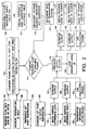
- FIG. 2 is a operational flow diagram for the temperature control system of Figure 1.
- Figure 1 illustrates a demand anticipation control (DAC) system 10 for an exemplary UPDI fluid heater A.
- DAC demand anticipation control
- the DAC system 10 includes a controller 12 incorporating conventional hardware such as a microprocessor-based central processing unit (CPU) 14 and supporting circuits and/or devices (not shown) such as RAM, ROM, I/O, etc. A user may communicate with the controller via an interface 16 such as keyboard or keypad.
- the DAC system 10 provides temperature control for the fluid heater A.
- the fluid heater A is positioned in series between a supply 22 of UPDI water and process equipment 24 which utilizes heated UPDI during the manufacture of semiconductor devices.
- the fluid heater A includes a housing 26 having a fluid inlet 28 coupled to the UPDI water supply 22, and a fluid outlet 30 coupled to the process equipment 24. At least one fluid pathway 32 extends through the housing 26 between the fluid inlet 28 and fluid outlet 30. A heating element 34 also extends through the housing 26 in close proximity to, yet sealed or isolated from, the fluid pathway 32.
- the heating element 34 includes a resistive wire 36 such as a Nichrome (NiCr) resistive wire switchably connected between a source of electrical power 38 and a ground potential 40.
- the resistive wire 36 heats fluid flowing through the fluid pathway 32 by means of conduction, convection, and/or radiation.
- the nominal operating temperature of the Nichrome wire 36 is approximately 1400°-1450°F (760°-788°C) with a maximum operating temperature rating of approximately 1700°F (927°C). It should be appreciated that the heater wire 36 can vary from ambient to the maximum operating temperature (e.g. 1700°F/927°C) based upon the heater design and required output power.
- a first temperature sensor 42 is positioned proximate the fluid inlet 28 and is coupled to the controller 12 via an input line 44.
- the temperature sensor 42 measures or otherwise determines the temperature of the fluid entering the fluid heater A.
- the resulting inlet temperature value is available for use by the controller.
- a second temperature sensor 46 is positioned proximate the fluid outlet 30 and is coupled to the controller 12 via an input line 48. The temperature sensor 46 measures or otherwise determines the temperature of the fluid leaving the fluid heater A.
- a flow sensor 50 is coupled to the controller via an input line 52 and measures or otherwise determines the rate of fluid flowing through the fluid pathway 32.
- An ampere sensor 54 or other device for determining the level of electrical current flowing through the resistive wire 36 is coupled to the controller 12 via an input line 56.
- a voltage sensor 58 or other device for determining the voltage drop across the resistive wire 36 is coupled to the controller via an input line 60.
- a resistance sensor 62 or other device for determining the resistance of the resistive wire 36 is coupled to the controller via an input line 64.
- a switching device 66 controls the application of electrical power to the resistive wire 36.
- a control terminal of the switching device 66 is connected to the controller 12 via an output control line 68.
- the switching device 66 can be a solid-state relay such as a silicon-controlled rectifier (SCR) that provides time-based, duty-cycle control of the power being applied to the resistive wire 36.
- SCR silicon-controlled rectifier
- a third temperature sensor 70 such as a thermocouple, measures or otherwise determines the operating temperature of the resistive wire 36, and is connected to the controller via an input line 72.
- the demand anticipation control system 10 provides accurate temperature control over a broad range of loads. What is meant herein by use of the term “load” is the rate of fluid flowing through the fluid heater, and in particular the fluid pathway 32, such as in litres/minute (LPM) or gallons/minute (GPM).
- LPM litres/minute
- GPM gallons/minute
- a user of the system inputs a desired operating temperature or set point into the controller 12 via the input device 16.
- the controller 1) determines the power required to bring the load to the set point temperature by using the input values measured or otherwise determined by one or more of the sensors, 2) determines the actual power being applied to the resistive wire 36, 3) compares the actual power to the theoretical power level necessary to achieve the set point temperature, and 4) thereafter continuously adjusts the actual power applied to the resistive wire in real time to achieve the set point fluid temperature at the output 30 of the fluid heater.
- This method of calculating the actual power being applied to the resistive wire allows for universal heater application, without the need to define a temperature/resistance curve or look-up table for each type of resistance wire used, as described further below.
- a less accurate and lower cost method of determining the actual power being applied to the resistive wire 36 is to first determine the temperature of the resistive wire, such as by temperature sensor 70.
- the measured temperature value can be compared with a known temperature vs. resistance curve, look-up table, or fourth order polynomial describing the curve, for the particular type of resistance wire used. That is, the resistance of the wire 36 is a function of its operating temperature.
- a user can enter a value into the controller 12 that represents the rated power of the resistive wire 36 when it is operating at the rated temperature.
- the actual resistance for single phase power is about 4.608 ohms.
- the design resistance is only 4.367 ohms. If the resistance did not change with temperature, the power at 480 volts would be 52.76 kW.
- the applied voltage is reduced via the controller 12, the wire temperature cools, and the resistance goes down. Assuming for ease of explanation, that the power needed was one-fourth of the heater capacity. Following Ohm's law equation (4), since it is a square function, one-half of the voltage should produce one-fourth of the power.
- 2402/4.487 12.836 kW, .300 kW more than needed to achieve the set point temperature.
- the resistance value (4.487) falls between the cold resistance value and the design resistance value (the actual value would be determined from a look-up table for NiCr wire. This function corrects for the error by simply changing voltage as a function of percentage of power.
- both the voltage drop across the resistance wire 36, measured by the sensor 58, and the resistance of the resistive wire 36, measured by the sensor 62, are determined in at least substantially real time. Applied power can therefore be determined from equation (2) above.
- a difference value can be obtained (block 114).
- the difference value may be expressed in terms of a percentage increase or percentage decrease of the power being applied to the resistive wire 36. Accordingly, the power being applied to the resistive wire 36 (block 116), is adjusted, in part, based on the difference value obtained in block 114 (block 118).
- Determining all the required parameters, and determining power needed provides instant correction to maintain accurate temperature control over any load within the capabilities of the heater system. Even though the system can respond to these changes, thermal lags in the system can result in temperature droops when going from a small load to a large load, and conversely temperature over-shoots when going from a large load to a small load. To reduce this effect, the DAC system 10 adjusts the power applied to the resistive wire when the rate of change of the fluid temperature up or down exceeds an acceptable range.
- the DAC system 10 boosts, or reduces the power applied to the resistive wire 36 as a function of the rate of temperature change between the inlet fluid temperature and the outlet fluid temperature (block 120). If the rate of fluid temperature change is greater than a user-programmable or factory set point, (block 122), then the power applied to the resistive wire 36 is decreased until the rate of change is reduced to within a predetermined range (block 124). If the rate of fluid temperature change is less than a user programmable or factory set point, (block 126), then the power applied to the resistive wire 36 is increased until the rate of change is increased to within a predetermined range (block 128).
- the power applied to the resistive wire 36 is again continuously adjusted based on the percentage difference between the needed power (block 114) and the actual power (blocks 108, 110, or 112) (block 132).
- the DAC system 10 can also boost, or reduce the power applied to the heating element as a function of the fluid temperature difference (e.g. temperature offset) from the set point. That is, the set point value is compared with the temperature of the fluid at the outlet 30 (block 140), as measured by the temperature sensor 46.
- the fluid temperature difference e.g. temperature offset
- the power applied to the resistive wire 36 is increased until the offset is reduced to within a predetermined range (block 144). If the outlet temperature is greater than the set point by more than a preset difference level (block 146), then the power applied to the resistive wire 36 is decreased until the offset is reduced to within the predetermined range (block 148). Once the outlet temperature is determined to be within an acceptable range of the set point (block 150), then the power level is again adjusted based on the percentage difference between the needed power (block 114) and the actual power (blocks 108, 110, or 112) (block 152).
Landscapes
- Engineering & Computer Science (AREA)
- Physics & Mathematics (AREA)
- Combustion & Propulsion (AREA)
- General Engineering & Computer Science (AREA)
- Mechanical Engineering (AREA)
- Thermal Sciences (AREA)
- Chemical & Material Sciences (AREA)
- Automation & Control Theory (AREA)
- General Physics & Mathematics (AREA)
- Remote Sensing (AREA)
- Fluid Mechanics (AREA)
- Computer Hardware Design (AREA)
- Control Of Resistance Heating (AREA)
- Heat-Pump Type And Storage Water Heaters (AREA)
- Steam Or Hot-Water Central Heating Systems (AREA)
- Resistance Heating (AREA)
- Instantaneous Water Boilers, Portable Hot-Water Supply Apparatuses, And Control Of Portable Hot-Water Supply Apparatuses (AREA)
Claims (15)
- Temperatursteuerungssystem (10) für einen Fluiderwärmer, einschließend ein Gehäuse (26) mit einem Einlaß (28) und einem Auslaß (30), wenigstens einen Fluidweg (32) durch das Gehäuse und ein Heizelement (34) proximal zum Fluidweg zum Erwärmen eines Betriebsfluidflusses durch den Weg, wobei das Steuerungssystem aufweist:einen Einlaßtemperatursensor (42) zur Bestimmung der Temperatur des Betriebsfluids am Einlaß;einen Strömungssensor (50) zum Bestimmen der Rate des Betriebsfluidflusses durch den Fluidweg;eine Schaltvorrichtung (66), die verbunden ist zwischen einer elektrischen Energiequelle/Leistungsquelle (38) und dem Heizelement; undeinen Controller (12) in Verbindung mit dem Temperatursensor, dem Strömungssensor und der Schaltvorrichtung, wobei der Controller beinhaltet:erste/erstes Mittel zur Bestimmung eines ersten Energiewertes/Leistungswertes, basierend auf Eingaben (52,44) vom Einlaßtemperatursensor und dem Strömungssensor, wobei der erste Energiewert/Leistungswert anzeigend ist für einen Energielevel, der benötigt wird, um das Betriebsfluid auf eine Sollwert-Temperatur zu erwärmen,
dadurch gekennzeichnet, daß der Controller weiterhin beinhaltet zweite/zweites Mittel (54,56,58,60) zur Bestimmung eines zweiten Energiewertes/Leistungswertes, korrespondierend zur aktuellen elektrischen Energie/Leistung, die dem Heizelement zugeführt wird, unddritte/drittes Mittel (14) zur Steuerung der Schaltvorrichtung, basierend auf einer Differenz zwischen dem ersten Energiewert/Leistungswert und dem zweiten Energiewert/Leistungswert. - Temperatursteuerungssystem nach Anspruch 1, wobei das Heizelement (34) ein Widerstandsheizelement ist.
- Temperatursteuerungssystem nach Anspruch 2, weiterhin beinhaltend:einen Stromsensor (54) zur Bestimmung eines Stromlevels, der durch das Widerstandsheizelement fließt;einen Spannungssensor (58) zur Bestimmung eines Spannungsabfalls über dem Widerstandsheizelement; unddie zweiten Mittel/das zweite Mittel den zweiten Energiewert/Leistungswert bestimmen/bestimmt, basierend auf den Eingaben aus dem Stromsensor und dem Spannungssensor.
- Temperatursteuerungssystem nach Anspruch 2, weiterhin beinhaltend:einen zweiten Temperatursensor (70) zur Bestimmung einer Betriebstemperatur des Widerstandsheizelementes;Mittel (14) zur Bestimmung eines Widerstandswertes des Widerstandsheizelementes, basierend auf einer Eingabe (72) vom zweiten Temperatursensor;die zweiten Mittel/das zweite Mittel, die/das den zweiten Energiewert/Leistungswert bestimmen/bestimmt, basierend auf dem Widerstandswert.
- Temperatursteuerungssystem nach Anspruch 2, weiterhin beinhaltend:einen Widerstandssensor (62) zur Bestimmung eines Widerstandswertes des Widerstandsheizelementes;einen Spannungssensor (58) zur Bestimmung eines Spannungsabfalls über dem Widerstandsheizelement; unddie zweiten Mittel/das zweite Mittel, die/das den zweiten Energiewert/Leistungswert bestimmen/bestimmt, basierend auf Eingaben (64,60) vom Widerstandssensor und dem Spannungssensor.
- Temperatursteuerungssystem nach Anspruch 1, weiterhin beinhaltend:einen Auslaßtemperatursensor (46) zur Bestimmung einer Temperatur des Fluids am Auslaß; undvierte/viertes Mittel, die/das verbunden sind/ist mit dem Controller zum Überlagern der/des dritten Mittel/Mittels, wenn eine Änderungsrate zwischen der Temperatur des Fluids am Einlaß und der Temperatur des Fluids am Auslaß größer ist als eine erste Änderungssollwertrate oder kleiner als eine zweite Änderungssollwertrate ist.
- Temperatursteuerungssystem nach Anspruch 1, weiterhin beinhaltend:einen Auslaßtemperatursensor (46) zur Bestimmung einer Temperatur des Fluids am Auslaß; undvierte/viertes Mittel, die/das verbunden sind/ist mit dem Controller zum Überlagern der/des dritten Mittel/Mittels, wenn eine Differenz zwischen der Temperatur des Fluids am Einlaß und der Temperatur des Fluids am Auslaß größer ist als ein erster Temperaturdifferenzsollwert oder kleiner als ein zweiter Temperaturdifferenzsollwert ist.
- Temperatursteuerungssystem nach Anspruch 1, wobei die Schaltvorrichtung (66) ein Halbleiterrelais ist.
- Temperatursteuerungssystem nach Anspruch 1, weiterhin beinhaltend eine Benutzerschnittstelle (16), die mit dem Controller zur Eingabe der Sollwert-Temperatur kommuniziert.
- Verfahren zur Steuerung der Temperatur in einem Fluiderwärmer, einschließend ein Gehäuse (26) mit einem Einlaß (28) und einem Auslaß (30), wenigstens einen Fluidweg (32) durch das Gehäuse, ein Heizelement (34) proximal zum Fluidweg zum Erwärmen eines Betriebsfluidflusses durch den Weg, und eine Schaltvorrichtung (66), die verbunden ist zwischen einer elektrischen Energiequelle/Leistungsquelle (38) und dem Heizelement, wobei das Verfahren die folgenden Schritte aufweist:a) Messen der Temperatur des Betriebsfluids am Einlaß;b) Messen der Betriebsfluidflußrate durch den Fluidweg;c) Berechnung eines ersten Energiewertes/Leistungswertes, basierend auf der Temperatur des Betriebsfluids am Einlaß und der Betriebsfluidflußrate durch den Einlaß, wobei der erste Energiewert/Leistungswert anzeigend für einen Energielevel/Leistungslevel ist, der benötigt wird, um das Betriebsfluid auf eine erste Sollwert-Temperatur zu erwärmen;
wobei das Verfahren gekennzeichnet ist durch die Schritte:d) Messen eines zweiten Energiewertes/Leistungswertes, korrespondierend mit der zum Heizelement gespeisten aktuellen elektrischen Energie/Leistung; unde) Steuerung der Schaltvorrichtung, basierend auf einer Differenz zwischen dem ersten Energiewert/ Leistungswert und dem zweiten Energiewert/Leistungswert. - Verfahren nach Anspruch 10, wobei Schritt d) beinhaltet:Messen eines Stromflußlevels durch das Heizelement (34);Messen eines Spannungsabfalls über dem Heizelement; undBestimmung des zweiten Energiewertes/Leistungswertes, basierend auf dem Stromflußlevel durch das Heizelement und dem Spannungsabfall über dem Heizelement.
- Verfahren nach Anspruch 10, wobei Schritt d) beinhaltet:Messen einer Betriebstemperatur des Heizelementes (34) ;Messen eines Widerstandswertes des Heizelementes, basierend auf der Betriebstemperatur des Heizelementes; undBestimmung des zweiten Energiewertes/Leistungswertes, basierend auf dem Widerstandswert des Heizelementes.
- Verfahren nach Anspruch 10, wobei Schritt d) beinhaltet:Messen eines Widerstandswertes des Heizelementes;Messen eines Spannungsabfalls über dem Heizelement; undBestimmung des zweiten Energiewertes/Leistungswertes, basierend auf dem Widerstandswert des Heizelementes und dem Spannungsabfall über dem Heizelement.
- Verfahren nach Anspruch 10, weiterhin beinhaltend:f) Messen einer Temperatur des Betriebsfluids am Auslaß (30); undg) Überlagern des Schrittes e), wenn eine Änderungsrate zwischen der Temperatur des Fluids am Einlaß (28) und der Temperatur des Fluids am Auslaß größer ist als eine erste Änderungssollwertrate oder kleiner ist als eine zweite Änderungssollwertrate.
- Verfahren nach Anspruch 10, weiterhin beinhaltend:f) Messen einer Temperatur des Betriebsfluids am Auslaß (30); undg) Überlagerung des Schrittes e), wenn eine Differenz zwischen der Temperatur des Fluids am Einlaß (28) und der Temperatur des Fluids am Auslaß größer ist als ein erster Temperaturdifferenzsollwert oder kleiner ist als ein zweiter Temperaturdifferenzsollwert.
Applications Claiming Priority (3)
| Application Number | Priority Date | Filing Date | Title |
|---|---|---|---|
| US7232198P | 1998-01-23 | 1998-01-23 | |
| US72321P | 1998-01-23 | ||
| PCT/US1999/001430 WO1999038356A1 (en) | 1998-01-23 | 1999-01-22 | Demand anticipation control system for a high efficiency ultra-pure fluid heater |
Publications (3)
| Publication Number | Publication Date |
|---|---|
| EP1048188A1 EP1048188A1 (de) | 2000-11-02 |
| EP1048188A4 EP1048188A4 (de) | 2002-08-21 |
| EP1048188B1 true EP1048188B1 (de) | 2004-05-26 |
Family
ID=22106875
Family Applications (1)
| Application Number | Title | Priority Date | Filing Date |
|---|---|---|---|
| EP99903327A Expired - Lifetime EP1048188B1 (de) | 1998-01-23 | 1999-01-22 | Steuerungssystem mit vorzeitiger befragung für eine erhitzungsvorrichtung bestimmt für die erwärmung von ultrareinen flüssigkeiten. |
Country Status (6)
| Country | Link |
|---|---|
| US (1) | US6178291B1 (de) |
| EP (1) | EP1048188B1 (de) |
| JP (1) | JP3929699B2 (de) |
| AT (1) | ATE268098T1 (de) |
| DE (1) | DE69917603T2 (de) |
| WO (1) | WO1999038356A1 (de) |
Cited By (1)
| Publication number | Priority date | Publication date | Assignee | Title |
|---|---|---|---|---|
| CN112484311A (zh) * | 2020-12-03 | 2021-03-12 | 芜湖美的厨卫电器制造有限公司 | 用于热水器的控制方法、装置、热水器及处理器 |
Families Citing this family (16)
| Publication number | Priority date | Publication date | Assignee | Title |
|---|---|---|---|---|
| US6229957B1 (en) * | 1999-05-14 | 2001-05-08 | Joseph Baker | Physiological fluid warming process and apparatus |
| FR2835910B3 (fr) * | 2002-02-14 | 2004-03-12 | Rid Soc | Controle de temperature auto adaptable destine a la regulation de generateur de chaleur ou de froid traitant des liquides |
| US6806446B1 (en) | 2002-10-04 | 2004-10-19 | Stephen D. Neale | Power management controls for electric appliances |
| US7712677B1 (en) * | 2003-03-05 | 2010-05-11 | Honeywell International Inc. | Water heater and control |
| US8029454B2 (en) | 2003-11-05 | 2011-10-04 | Baxter International Inc. | High convection home hemodialysis/hemofiltration and sorbent system |
| US7305569B2 (en) * | 2004-06-29 | 2007-12-04 | Intel Corporation | Apparatus, system and method for adjusting a set of actual power states according to a function depending on a set of desired power states |
| US7117825B2 (en) * | 2004-06-30 | 2006-10-10 | Synapse, Inc. | System and method for preventing overheating of water within a water heater tank |
| US8165726B2 (en) * | 2006-01-30 | 2012-04-24 | Honeywell International Inc. | Water heater energy savings algorithm for reducing cold water complaints |
| US8078333B2 (en) | 2007-07-05 | 2011-12-13 | Baxter International Inc. | Dialysis fluid heating algorithms |
| EP2085715A1 (de) * | 2008-01-29 | 2009-08-05 | Societe Des Produits Nestle S.A. | System zum Ändern der Flüssigkeitstemperatur und Verfahren zur Steuerung eines solchen Systems |
| US8770152B2 (en) * | 2008-10-21 | 2014-07-08 | Honeywell International Inc. | Water Heater with partially thermally isolated temperature sensor |
| US8218955B2 (en) * | 2008-12-30 | 2012-07-10 | Hatco Corporation | Method and system for reducing response time in booster water heating applications |
| KR20120111906A (ko) | 2011-04-01 | 2012-10-11 | 웅진코웨이주식회사 | 온수공급장치 및 온수공급방법 |
| US9303897B2 (en) | 2012-06-12 | 2016-04-05 | Emerson Electric Co. | Compensating for sensor thermal lag |
| BR112015025993A2 (pt) | 2013-04-12 | 2020-08-11 | Pentair Pump Group, Inc. | sistema e método de controle de reforçador hidráulico |
| US11060764B2 (en) | 2018-11-13 | 2021-07-13 | White Knight Fluid Handling Inc. | On-demand heater and temperature control system and related process |
Family Cites Families (19)
| Publication number | Priority date | Publication date | Assignee | Title |
|---|---|---|---|---|
| US3952182A (en) * | 1974-01-25 | 1976-04-20 | Flanders Robert D | Instantaneous electric fluid heater |
| US4158764A (en) * | 1975-06-24 | 1979-06-19 | Yane Frank J | Device for heating liquid in a container |
| US4337388A (en) | 1980-05-29 | 1982-06-29 | July Mark E | Rapid-response water heating and delivery system |
| US4567350A (en) * | 1983-01-06 | 1986-01-28 | Todd Jr Alvin E | Compact high flow rate electric instantaneous water heater |
| US4553024A (en) * | 1983-04-07 | 1985-11-12 | Lufran, Inc. | Gas-purged flexible cable-type immersion heater and method for heating highly corrosive liquids |
| GB2148467B (en) * | 1983-10-18 | 1988-04-13 | Gainsborough Electrical | Water heaters |
| US4713525A (en) | 1986-07-23 | 1987-12-15 | Kowah, Inc. | Microcomputer controlled instant electric water heating and delivery system |
| US4835365A (en) * | 1986-09-29 | 1989-05-30 | Etheridge David R | De-ionized fluid heater and control system |
| GB8903744D0 (en) * | 1989-02-18 | 1989-04-05 | Endress & Hauser Ltd | Flowmeter |
| US4970373A (en) * | 1989-12-11 | 1990-11-13 | Keltech, Inc. | Electronic temperature control system for a tankless water heater |
| US5325822A (en) * | 1991-10-22 | 1994-07-05 | Fernandez Guillermo N | Electrtic, modular tankless fluids heater |
| US5396574A (en) * | 1992-03-26 | 1995-03-07 | Process Technology, Inc. | Tubular high efficiency, non-contaminating fluid heater |
| US5438642A (en) | 1993-07-13 | 1995-08-01 | Instantaneous Thermal Systems, Inc. | Instantaneous water heater |
| WO1996002029A1 (en) * | 1994-07-07 | 1996-01-25 | Honeywell Inc. | Trim heater controller |
| US5437003A (en) * | 1994-12-16 | 1995-07-25 | Hot Aqua Industries, Inc. | In line tankless water heater with upper heating compartment, lower wiring compartment, and microswitch compartment disposed therebetween |
| US5590240A (en) | 1995-05-30 | 1996-12-31 | Process Technology Inc | Ultra pure water heater with coaxial helical flow paths |
| AU7016396A (en) * | 1995-10-10 | 1997-04-30 | Donald Kuhnel | Fluid heater with improved heating elements controller |
| US5919386A (en) * | 1996-06-18 | 1999-07-06 | Lufran Incorporated | Purge management system for gas purged immersion heaters |
| US6080971A (en) * | 1997-05-22 | 2000-06-27 | David Seitz | Fluid heater with improved heating elements controller |
-
1999
- 1999-01-22 JP JP2000529107A patent/JP3929699B2/ja not_active Expired - Lifetime
- 1999-01-22 WO PCT/US1999/001430 patent/WO1999038356A1/en active IP Right Grant
- 1999-01-22 DE DE69917603T patent/DE69917603T2/de not_active Expired - Lifetime
- 1999-01-22 EP EP99903327A patent/EP1048188B1/de not_active Expired - Lifetime
- 1999-01-22 AT AT99903327T patent/ATE268098T1/de active
- 1999-01-22 US US09/235,199 patent/US6178291B1/en not_active Expired - Lifetime
Cited By (2)
| Publication number | Priority date | Publication date | Assignee | Title |
|---|---|---|---|---|
| CN112484311A (zh) * | 2020-12-03 | 2021-03-12 | 芜湖美的厨卫电器制造有限公司 | 用于热水器的控制方法、装置、热水器及处理器 |
| CN112484311B (zh) * | 2020-12-03 | 2022-07-15 | 芜湖美的厨卫电器制造有限公司 | 用于热水器的控制方法、装置、热水器及处理器 |
Also Published As
| Publication number | Publication date |
|---|---|
| DE69917603T2 (de) | 2005-05-25 |
| EP1048188A1 (de) | 2000-11-02 |
| JP3929699B2 (ja) | 2007-06-13 |
| JP2002502016A (ja) | 2002-01-22 |
| EP1048188A4 (de) | 2002-08-21 |
| WO1999038356A1 (en) | 1999-07-29 |
| US6178291B1 (en) | 2001-01-23 |
| DE69917603D1 (de) | 2004-07-01 |
| ATE268098T1 (de) | 2004-06-15 |
Similar Documents
| Publication | Publication Date | Title |
|---|---|---|
| EP1048188B1 (de) | Steuerungssystem mit vorzeitiger befragung für eine erhitzungsvorrichtung bestimmt für die erwärmung von ultrareinen flüssigkeiten. | |
| US20230021550A1 (en) | Power converter for a thermal system | |
| CN106873662B (zh) | 温度控制系统及其方法 | |
| US11038431B2 (en) | Isolated power converter for a thermal system | |
| KR20230042686A (ko) | 정수기의 제어장치, 정수기 및 이의 제어방법 | |
| US20130022340A1 (en) | Apparatus for delivering a medium at an adjustable temperature | |
| US7364095B2 (en) | Apparatus for judging target to be temperature-regulated | |
| JP3181511B2 (ja) | ノズルヒータの給電制御方法および給電制御装置 | |
| US20220075399A1 (en) | Method and system for controlling an electric heater using control on energy | |
| JP5313848B2 (ja) | 送水圧力制御システムおよび方法 | |
| GB2375591A (en) | Electric shower with automatic control | |
| FI83926B (fi) | Foerfarande foer reglering av effekten i en elektrisk bastuugn. | |
| JP2002140119A (ja) | ワーク温度制御装置 | |
| JP3809483B2 (ja) | 半導体製造装置の制御方法 | |
| JP2014211386A (ja) | クロマトグラフ用恒温槽 | |
| JPH01203845A (ja) | あと沸き防止装置付き給湯器 | |
| JPS645836Y2 (de) | ||
| WO2021226104A1 (en) | Isolated power converter for a thermal system | |
| JP2020020565A (ja) | 電気湯沸器 | |
| IL300443A (en) | Method and system for providing variable droop control to an electric heater | |
| JP2001201066A (ja) | 電力制御装置 | |
| JPH0827068B2 (ja) | 給湯装置 | |
| JPH0433112A (ja) | ヒータ制御装置 |
Legal Events
| Date | Code | Title | Description |
|---|---|---|---|
| PUAI | Public reference made under article 153(3) epc to a published international application that has entered the european phase |
Free format text: ORIGINAL CODE: 0009012 |
|
| 17P | Request for examination filed |
Effective date: 20000822 |
|
| AK | Designated contracting states |
Kind code of ref document: A1 Designated state(s): AT BE CH CY DE DK ES FI FR GB GR IE IT LI LU MC NL PT SE |
|
| RAP1 | Party data changed (applicant data changed or rights of an application transferred) |
Owner name: TOM RICHARDS, INC. |
|
| A4 | Supplementary search report drawn up and despatched |
Effective date: 20020708 |
|
| AK | Designated contracting states |
Kind code of ref document: A4 Designated state(s): AT BE CH CY DE DK ES FI FR GB GR IE IT LI LU MC NL PT SE |
|
| RIC1 | Information provided on ipc code assigned before grant |
Free format text: 7H 05B 3/04 A, 7H 05B 1/02 B, 7H 05B 3/82 B, 7F 24H 1/10 B, 7F 24H 9/20 B, 7G 05D 23/24 B |
|
| 17Q | First examination report despatched |
Effective date: 20021028 |
|
| GRAP | Despatch of communication of intention to grant a patent |
Free format text: ORIGINAL CODE: EPIDOSNIGR1 |
|
| GRAS | Grant fee paid |
Free format text: ORIGINAL CODE: EPIDOSNIGR3 |
|
| GRAA | (expected) grant |
Free format text: ORIGINAL CODE: 0009210 |
|
| AK | Designated contracting states |
Kind code of ref document: B1 Designated state(s): AT BE CH CY DE DK ES FI FR GB GR IE IT LI LU MC NL PT SE |
|
| PG25 | Lapsed in a contracting state [announced via postgrant information from national office to epo] |
Ref country code: NL Free format text: LAPSE BECAUSE OF FAILURE TO SUBMIT A TRANSLATION OF THE DESCRIPTION OR TO PAY THE FEE WITHIN THE PRESCRIBED TIME-LIMIT Effective date: 20040526 Ref country code: LI Free format text: LAPSE BECAUSE OF FAILURE TO SUBMIT A TRANSLATION OF THE DESCRIPTION OR TO PAY THE FEE WITHIN THE PRESCRIBED TIME-LIMIT Effective date: 20040526 Ref country code: FI Free format text: LAPSE BECAUSE OF FAILURE TO SUBMIT A TRANSLATION OF THE DESCRIPTION OR TO PAY THE FEE WITHIN THE PRESCRIBED TIME-LIMIT Effective date: 20040526 Ref country code: CH Free format text: LAPSE BECAUSE OF FAILURE TO SUBMIT A TRANSLATION OF THE DESCRIPTION OR TO PAY THE FEE WITHIN THE PRESCRIBED TIME-LIMIT Effective date: 20040526 Ref country code: BE Free format text: LAPSE BECAUSE OF FAILURE TO SUBMIT A TRANSLATION OF THE DESCRIPTION OR TO PAY THE FEE WITHIN THE PRESCRIBED TIME-LIMIT Effective date: 20040526 |
|
| REG | Reference to a national code |
Ref country code: GB Ref legal event code: FG4D |
|
| REG | Reference to a national code |
Ref country code: CH Ref legal event code: EP |
|
| REG | Reference to a national code |
Ref country code: IE Ref legal event code: FG4D |
|
| REF | Corresponds to: |
Ref document number: 69917603 Country of ref document: DE Date of ref document: 20040701 Kind code of ref document: P |
|
| PG25 | Lapsed in a contracting state [announced via postgrant information from national office to epo] |
Ref country code: SE Free format text: LAPSE BECAUSE OF FAILURE TO SUBMIT A TRANSLATION OF THE DESCRIPTION OR TO PAY THE FEE WITHIN THE PRESCRIBED TIME-LIMIT Effective date: 20040826 Ref country code: GR Free format text: LAPSE BECAUSE OF FAILURE TO SUBMIT A TRANSLATION OF THE DESCRIPTION OR TO PAY THE FEE WITHIN THE PRESCRIBED TIME-LIMIT Effective date: 20040826 Ref country code: DK Free format text: LAPSE BECAUSE OF FAILURE TO SUBMIT A TRANSLATION OF THE DESCRIPTION OR TO PAY THE FEE WITHIN THE PRESCRIBED TIME-LIMIT Effective date: 20040826 |
|
| PG25 | Lapsed in a contracting state [announced via postgrant information from national office to epo] |
Ref country code: ES Free format text: LAPSE BECAUSE OF FAILURE TO SUBMIT A TRANSLATION OF THE DESCRIPTION OR TO PAY THE FEE WITHIN THE PRESCRIBED TIME-LIMIT Effective date: 20040906 |
|
| REG | Reference to a national code |
Ref country code: CH Ref legal event code: PL |
|
| NLV1 | Nl: lapsed or annulled due to failure to fulfill the requirements of art. 29p and 29m of the patents act | ||
| ET | Fr: translation filed | ||
| PG25 | Lapsed in a contracting state [announced via postgrant information from national office to epo] |
Ref country code: LU Free format text: LAPSE BECAUSE OF NON-PAYMENT OF DUE FEES Effective date: 20050122 Ref country code: CY Free format text: LAPSE BECAUSE OF FAILURE TO SUBMIT A TRANSLATION OF THE DESCRIPTION OR TO PAY THE FEE WITHIN THE PRESCRIBED TIME-LIMIT Effective date: 20050122 |
|
| PG25 | Lapsed in a contracting state [announced via postgrant information from national office to epo] |
Ref country code: IE Free format text: LAPSE BECAUSE OF NON-PAYMENT OF DUE FEES Effective date: 20050124 |
|
| PG25 | Lapsed in a contracting state [announced via postgrant information from national office to epo] |
Ref country code: MC Free format text: LAPSE BECAUSE OF NON-PAYMENT OF DUE FEES Effective date: 20050131 |
|
| PLBE | No opposition filed within time limit |
Free format text: ORIGINAL CODE: 0009261 |
|
| STAA | Information on the status of an ep patent application or granted ep patent |
Free format text: STATUS: NO OPPOSITION FILED WITHIN TIME LIMIT |
|
| 26N | No opposition filed |
Effective date: 20050301 |
|
| REG | Reference to a national code |
Ref country code: IE Ref legal event code: MM4A |
|
| PG25 | Lapsed in a contracting state [announced via postgrant information from national office to epo] |
Ref country code: PT Free format text: LAPSE BECAUSE OF NON-PAYMENT OF DUE FEES Effective date: 20041026 |
|
| REG | Reference to a national code |
Ref country code: FR Ref legal event code: PLFP Year of fee payment: 18 |
|
| REG | Reference to a national code |
Ref country code: FR Ref legal event code: PLFP Year of fee payment: 19 |
|
| REG | Reference to a national code |
Ref country code: FR Ref legal event code: PLFP Year of fee payment: 20 |
|
| PGFP | Annual fee paid to national office [announced via postgrant information from national office to epo] |
Ref country code: FR Payment date: 20171220 Year of fee payment: 20 |
|
| PGFP | Annual fee paid to national office [announced via postgrant information from national office to epo] |
Ref country code: GB Payment date: 20171228 Year of fee payment: 20 |
|
| PGFP | Annual fee paid to national office [announced via postgrant information from national office to epo] |
Ref country code: DE Payment date: 20180109 Year of fee payment: 20 |
|
| PGFP | Annual fee paid to national office [announced via postgrant information from national office to epo] |
Ref country code: IT Payment date: 20180110 Year of fee payment: 20 Ref country code: AT Payment date: 20171228 Year of fee payment: 20 |
|
| REG | Reference to a national code |
Ref country code: DE Ref legal event code: R071 Ref document number: 69917603 Country of ref document: DE |
|
| REG | Reference to a national code |
Ref country code: GB Ref legal event code: PE20 Expiry date: 20190121 |
|
| REG | Reference to a national code |
Ref country code: AT Ref legal event code: MK07 Ref document number: 268098 Country of ref document: AT Kind code of ref document: T Effective date: 20190122 |
|
| PG25 | Lapsed in a contracting state [announced via postgrant information from national office to epo] |
Ref country code: GB Free format text: LAPSE BECAUSE OF EXPIRATION OF PROTECTION Effective date: 20190121 |