EP1047293A2 - Kühlkörperbefestigung und Verfahren - Google Patents
Kühlkörperbefestigung und Verfahren Download PDFInfo
- Publication number
- EP1047293A2 EP1047293A2 EP00303251A EP00303251A EP1047293A2 EP 1047293 A2 EP1047293 A2 EP 1047293A2 EP 00303251 A EP00303251 A EP 00303251A EP 00303251 A EP00303251 A EP 00303251A EP 1047293 A2 EP1047293 A2 EP 1047293A2
- Authority
- EP
- European Patent Office
- Prior art keywords
- ledge
- recited
- heat transfer
- defining
- substrate
- Prior art date
- Legal status (The legal status is an assumption and is not a legal conclusion. Google has not performed a legal analysis and makes no representation as to the accuracy of the status listed.)
- Withdrawn
Links
Images


Classifications
-
- H—ELECTRICITY
- H10—SEMICONDUCTOR DEVICES; ELECTRIC SOLID-STATE DEVICES NOT OTHERWISE PROVIDED FOR
- H10W—GENERIC PACKAGES, INTERCONNECTIONS, CONNECTORS OR OTHER CONSTRUCTIONAL DETAILS OF DEVICES COVERED BY CLASS H10
- H10W40/00—Arrangements for thermal protection or thermal control
- H10W40/60—Securing means for detachable heating or cooling arrangements, e.g. clamps
- H10W40/641—Snap-on arrangements, e.g. clips
Definitions
- the present invention is directed, in general, to a heat transfer device and, more specifically, to a heat transfer device that can be used alone or as a unit in a modular heat control system.
- a principle concern of electronic circuit designers is controlling the heat that is generated during operation of the circuit. Control of heat is vital to prevent component or circuit failure caused by heat buildup.
- the generally preferred method to control circuit and component heat is to dissipate it into the atmosphere around the circuit before temperatures rise to a damaging level. To do this, designers usually associate heat transfer devices, such as heat sinks, with heat generating components in the circuit. Heat sinks are designed to absorb the heat from the components and radiate the heat into the surrounding atmosphere.
- Heat transfer devices are generally composed of a material with favorable heat transfer, or thermal conductive, characteristics; that is, the material should be able to absorb heat and radiate heat into the surrounding atmosphere in an efficient manner.
- Several metals have favorable thermal conductive characteristics, including copper, aluminum, steel, and their alloys. Any one of these materials can be used as a heat sink, but aluminum is generally the preferred material because copper is expensive and steel is not very malleable. Another reason aluminum is favored is that extrusion processes are preferred in the manufacture of heat transfer devices, and such processes favor aluminum.
- heat spreaders can be mounted on the circuit substrate with heat generating components mounted on the spreaders.
- heat generating components mounted on the spreaders.
- spreaders frequently have to be specially designed, which increases the cost of the system and may create ancillary storage and handling problems during manufacture.
- These spreaders are frequently combined with custom heat transfer devices in the design of heat control systems.
- a heat transfer device that can be associated with a circuit and the heat generating components on the circuit using a simple attachment method requiring the use of substantially fewer parts in the assembly process than prior art methods.
- the device should advantageously handle a number of heat generating components and should lend itself to being used in the manufacture of low profile systems. Such a device would be most advantageously employed if it could also function as a component in combination with other devices in a heat control system as well as a stand alone heat control device.
- the present invention provides a heat transfer device for cooling an electronic component mounted to a substrate.
- the present invention also provides for a method to cool electronic components by using the heat transfer device and a method to manufacture the heat transfer device.
- One embodiment of the heat transfer device comprises an elongated body having opposing first and second major surfaces and opposing first and second minor surfaces; a mounting recess extending along a length of the second minor surface; a first ledge extending from the first major surface and defining a first component mounting area of a first lateral dimension; and a second ledge extending from the second major surface and defining a second component mounting area of a second lateral dimension, the second dimension differing from the first dimension.
- the present invention introduces a heat transfer device that can function either on a stand alone basis or as a component of a larger heat transfer system.
- the device has several favorable characteristics that provide a distinct advantage over prior art when used in low profile electronic systems.
- the device can be used alone as a heat transfer device to which heat generating components are attached, or it can be combined with other commercially available heat sinks to provide heat control for a larger number of devices. Because it can be used on a circuit in lieu of spreaders, it permits the design and manufacture of circuits using fewer parts, which provides a distinct cost advantage.
- a version of the device with the mounting recess configured to also serve as a cooling channel.
- Another embodiment provides for a channel extending along the length of the first minor surface, which channel is configured to dissipate heat and provide a receptacle for a spring clip to secure components to the device.
- Other aspects of the invention provide receptacles for spring clips to be used to secure components to the device.
- a first auxiliary ledge extends from the first major surface to parallel the first ledge and define a spring clip receptacle for a spring clip to secure components to the device.
- the device has a second auxiliary ledge extending from the second major surface to parallel the second ledge and define a spring clip receptacle for a spring clip to secure components to the device.
- a particularly advantageous iteration of the invention provides for pins that are press fit into the mounting recess, which pins are used to mount the device on a substrate by press fitting the pins into holes on the substrate.
- Another advantageous iteration of the device permits a heat sink to be releasably fastened to the first ledge or to the second ledge.
- the present invention also provides a method for cooling an electronic component mounted to a substrate.
- the heat transfer device is fastened to a substrate, other heat transfer devices can be combined with it in a modular system, which can be advantageously employed with low profile or compact electronic systems.
- the claimed method calls for extruding the device, which extrusion can include any number of the various embodiments claimed.
- the fact that the extrusion can be cut to any length deemed necessary is a particularly attractive and desirable feature of the invention. It permits the device to be tailored to the size of the substrate on which it will be mounted as well as the number of components with which it will be combined.
- FIGURE 1A illustrated is an isometric view of a heat transfer device 100 constructed according to the principles of the present invention.
- the device 100 represents a particularly favorable embodiment of the present invention.
- the device 100 has an elongated body 110 with opposing first and second major surfaces 120, 130 and opposing first and second minor surfaces 140, 150.
- a mounting recess 155 extends along the length of the second minor surface 150.
- a first ledge 125 extends from the first major surface 120 of the device 100.
- a second component mounting area 131 of a second lateral dimension extendends from the second major surface 130.
- the first lateral dimension A-B differs from the second lateral dimension C-D so that two different sizes of heat generating components can be mounted on the heat transfer device 100. For example, one side can mount only the shorter TO-220 electronic components while the other can accommodate both TO-220 components as well as the larger TO-247 components.
- a beneficial aspect of the illustrated embodiment of the device 100 is the number of cooling features incorporated into the device's 100 structure.
- One such feature is the cooling channel 141 that runs along the length of the first minor surface 140.
- the mounting recess 155 is also configured to serve as a cooling channel that runs the length of the second minor surface 150.
- Other cooling features include the first auxiliary ledge 126 that extends from the first major surface 120 parallel to the first ledge 125.
- the second auxiliary ledge 136 extending from the second major surface 130 parallel to the second ledge 135.
- first major surface 120, second major surface 130, first ledge 125, second ledge 135, first auxiliary ledge 126, second auxiliary ledge 136, cooling channel 141, and mounting recess 155 provides sufficient surface area so that the illustrated device 100 can serve as a stand alone heat sink.
- this stand alone feature represents a significant advantage over prior art because of its increased surface area.
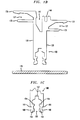
- FIGURE 1B illustrated is an end elevational view of the heat transfer device 100 of FIGURE 1A. To visualize how the device 100 relates to the substrate 170 of a printed wiring or circuit board, the device 100 is illustrated in a suspended position over the substrate 170 on which it is to be mounted.
- first ledge 125 and the first auxiliary ledge 126 both of which extend from the first major surface 120, is clear in this FIGURE 1B, as is the relationship between the second ledge 135 and second auxiliary ledge 136 extending from the second major surface 130.
- the first ledge 125 and first auxiliary ledge 126 are shaped to define a receptacle 127 that receives a spring clip securing components to the device 100.
- a similar receptacle 137 is defined by the second ledge 135 and second auxiliary ledge 136 on the second major surface.
- a similar receptacle 141 is also formed by the cooling channel 141 that extends along the length of the first minor surface 140. All three of the receptacles 127, 137, 141 have a similar shape to receive the same type of spring clip and secure components or other devices to the heat transfer device 100.
- FIGURE 1C illustrated is an end elevational view of the mounting recess 155 of one embodiment of the heat transfer device 100.
- the mounting recess has first and second snap grooves 153,154 inside the mounting recess. This permits the heat transfer device 100 to be mounted on a substrate in two stages. In the first stage the first snap grooves 153 can secure the heat transfer device 100 in a partially mounted position in order to make more room for working around the heat transfer device 100 during the assembly process. When it is determined that the heat transfer device 100 is ready to be completely installed, the second snap grooves 154 hold the device 100 in its fully installed position together with the external snap fit 160.
- a pin stop channel 157 At the top of the mounting recess is a pin stop channel 157 to receive the top of pins in the substrate that the heat transfer device 100 is mounted upon.
- the exterior also has an insulator alignment groove 161 to properly align the heat transfer device.
- FIGURE 2A illustrated is an isometric view of the heat transfer device 100 of FIGURE 1A, along with mounting pins 200 that may be employed to mount the heat transfer device 100 to a substrate.
- One end of the pin 200 may be press-fitted into the mounting recess 155 on the device 100.
- the other end of the pin 200 may then be positioned in a hole on the substrate provided for this purpose and then soldered.
- FIGURE 2B illustrated is a sectional end view of the mounting pins 200 of FIGURE 2A engaged within the mounting recess 155 of the heat transfer device 100 of FIGURES 1A or 2A.
- the mounting recess 155 on this embodiment of the device 100 has channels 156 around the pins 200 that provide an air bypass route for air to circulate through the mounting recess 155 with pins 200 installed.
- This feature provides additional cooling when the device 100 is mounted on a substrate by conduction as well as convection.
- pins 200 are soldered to the substrate, the pins 200 provide an additional cooling mechanism because it provides a conduction route to the copper planes of the substrate.
- the mounting recess 155 is designed so that the pins 200 length is precisely controlled when they are inserted to stop at pin stop 157 as shown on FIGURE 1C.
- the channels 156 in the mounting recess 155, in conjunction with the pins 200 enhance heat transfer characteristics by changing laminar air flow to turbulent air flow.
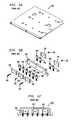
- FIGURE 3A illustrated is an isometric view of a heatsink top plate cover 300 for an assembled electronic circuit (not illustrated).
- the cover 300 is placed over a circuit by fastening it to the top of one or more spreaders 350 of the type illustrated in FIGURE 3B with many screws 361, nuts 363,and clamps 362.
- FIGURE 3B illustrates an exploded isometric view of a prior art spreader assembly that may be employed with the cover 300 of FIGURE 3A.
- FIGURE 3B shows a prior art spreader 350 with the various parts and heat generating components 360 that are required to be assembled in the course of completing an electronic assembly.
- FIGURE 3C illustrates the assembled spreader 350 with electronic components 360 mounted thereon by retainers 362.
- the components 360 are fastened to the spreader 350 by inserting small screws 361 through retainers 362 that hold the components 360 in place, and then through the spreader 350.
- the screws 361 are secured to the spreader 350 by small nuts 363.
- the spreader 350, with components 360 attached, is fastened to a substrate, over which a cover 300 is placed by attaching it to the top of one or more spreaders 350 by multiple screws (not shown).
- the total height of the assembled electronic system should advantageously be at least equal to the height of the tallest electronic component on the substrate, frequently a capacitor or magnetic element. If the desired system height is less than the height of the tallest component, a hole should advantageously be cut in the top plate heat sink cover 300 to accommodate the component.
- An additional disadvantage of covers 300 of the type illustrated, is that most electronic systems require custom made covers 300 that cannot be used on other products. This means that a limited number of pieces in a product line will require a small number of covers 300, with a relatively high cost to make each cover 300. It also complicates inventory control when a number of products are being manufactured if each product requires a different cover. Because the heat transfer device 100 described herein can eliminate the requirement for individually designed covers 300, the cost to manufacture certain electronic systems can be reduced.
- FIGURE 3B The number of small parts required to complete a spreader 350 assembly is apparent in FIGURE 3B.
- a heat spreader 350 assembly such as that illustrated, requires a number of small parts, the total assembly cost is increased because of the additional labor required.
- the present invention offers the opportunity to reduce complexity so no additional fixtures, pneumatic tools or complex assembly procedures are required to complete an electronic system. Costs are further reduced because fixtures do not have to be stored.
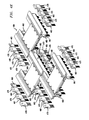
- FIGURES 4A through 4C an advantageous embodiment of the invention is illustrated that addresses certain of the prior art problems discussed above. Illustrated are two heat transfer devices 100 that are to be mounted on a substrate and a commercially available heat sink 400 to provide additional cooling.
- the commercial heat sink 400 also serves as a heat transfer device and protective cover for all or a portion of the circuit.
- FIGURE 4A illustrates an exploded isometric view of two heat transfer devices 100 of the type illustrated in FIGURES 1A and 2A and a commercially available heat sink 400.
- the first major surface 120 on each device 100 is illustrated as facing the first major surface 120 on the other device 100.
- the auxiliary ledges 126 on each device 100 are of the same height and opposite one another.
- the heat sink 400 is mounted on the devices 100 using the auxiliary ledges 126 for support.
- FIGURE 4B illustrated is an assembled isometric view of the assembly of FIGURE 4A.
- the heat sink 400 as a top plate cover.
- heat transfer devices 100 can be cut to different lengths. These different length devices 100 can be combined with different designs and sizes of commercially available mass produced heat sinks 400 to permit circuit designers to use this embodiment of the invention in lieu of custom-made top heat sink covers 300.
- FIGURE 4C illustrated is an end view of the assembly of FIGURE 4B, and two sizes of electronic components 460, 470 held in place by spring clips 455, 456, 457.
- the spring clips 455, 456, and 457 are used to secure the components 460 and 470 and spring clip 458 secures the heat sink 400 to the devices 100.
- the spring clips 455, 457, 458 may be substantially the same if each of three spring receptacles 127, 137, 141 are substantially identical.
- the device 100 permits two different sizes of heat generating components 460, 470 to be fastened to its major surfaces 120, 130. This is possible because two different sizes of component mounting areas 121, 131 are provided.
- the first component mounting area 121 on the first major surface 120 has a heat generating component 460 of one size mounted thereon, while mounted on the second component mounting area 131 on the second major surface 130 is a larger heat generating component 470.
- the second advantageous feature illustrated in FIGURE 4C is the way the electronic components 460, 470 and heat sink 400 are fastened to the device 100.
- the ability to fasten the various components 400, 460, 470 to the devices 100 with spring clips substantially reduces the number of parts required to complete an electronic assembly and, because clips go on easily, the assembly process is improved. These two features are particularly advantageous when used in subcompact electronic assemblies.
- each electronic component 460, 470 Extending from each electronic component 460, 470 are electrical leads 465, 475 to provide electrical connectivity between the components 460, 470 and the circuit on the substrate on which the device 100 is mounted.
- One embodiment of the device described in the above-referenced copending patent application provides for guides to align and connect the leads 465, 475 to the substrate.
- a method to manufacture the invention illustrated herein is to use an extrusion process.
- the device 100 When the device 100 is formed by extrusion, the device 100 can be tailored to a desired length based on the size of the substrate on which it is mounted and the number and size of electronic components 460, 470 to be cooled. Extrusion can include any number of, or variation on, the various embodiments claimed herein. The actual method of manufacturing the device 100 is clear from the foregoing detailed description and illustrations.
- the present invention introduces a heat transfer device 100 that, as described herein, can function either on a stand alone basis or as a component of a larger heat transfer system. Because the device 100 has an abundance of cooling surface, it can be used alone as a heat transfer device to which heat generating components are attached, or it can be combined with other commercially available heat sinks to provide heat control for a larger number of electronic components.
- the design permits the device 100 to be used on a circuit in lieu of heat spreaders, which do not make good stand alone heat sinks, while permitting the design and manufacture of circuits using fewer parts and labor, both of which provide a distinct cost advantage.
- the device 100 has features that provide a distinct advantage over prior art devices when used in low profile electronic systems.
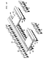
- FIGUREs 4D, 4E, and 4F illustrated are various configurations of heat transfer devices, commercially available heat sinks, and electronic components made possible by the present invention.
- the illustrated configurations clearly demonstrate the usefulness, versatility and flexibility of the invention. Of course, other configurations are clearly within the scope of the present invention.
Landscapes
- Cooling Or The Like Of Electrical Apparatus (AREA)
Applications Claiming Priority (2)
| Application Number | Priority Date | Filing Date | Title |
|---|---|---|---|
| US298427 | 1999-04-23 | ||
| US09/298,427 US6252773B1 (en) | 1999-04-23 | 1999-04-23 | Heat sink attachment apparatus and method |
Publications (2)
| Publication Number | Publication Date |
|---|---|
| EP1047293A2 true EP1047293A2 (de) | 2000-10-25 |
| EP1047293A3 EP1047293A3 (de) | 2002-01-30 |
Family
ID=23150472
Family Applications (1)
| Application Number | Title | Priority Date | Filing Date |
|---|---|---|---|
| EP00303251A Withdrawn EP1047293A3 (de) | 1999-04-23 | 2000-04-18 | Kühlkörperbefestigung und Verfahren |
Country Status (3)
| Country | Link |
|---|---|
| US (1) | US6252773B1 (de) |
| EP (1) | EP1047293A3 (de) |
| JP (1) | JP2000323877A (de) |
Cited By (2)
| Publication number | Priority date | Publication date | Assignee | Title |
|---|---|---|---|---|
| DE20120695U1 (de) * | 2001-12-20 | 2003-04-30 | Gebr. Jordan GmbH & Co KG, 58636 Iserlohn | Befestigungsklammer zum Befestigen eines elektrischen/elektronischen Elementes an einem Kühlkörper |
| EP1555692A3 (de) * | 2003-12-25 | 2011-02-02 | Aisin Seiki Kabushiki Kaisha | Befestigungsvorrichtung für elektronische Bauelemente |
Families Citing this family (19)
| Publication number | Priority date | Publication date | Assignee | Title |
|---|---|---|---|---|
| US6219246B1 (en) * | 1999-07-02 | 2001-04-17 | Powerware Corporation | Heat sink apparatus |
| JP4152575B2 (ja) * | 2000-09-28 | 2008-09-17 | 三菱電機株式会社 | 半導体装置 |
| AU2003225893A1 (en) * | 2002-03-21 | 2003-10-08 | Aavid Thermalloy, Llc | Support clip |
| US6858792B2 (en) * | 2002-12-19 | 2005-02-22 | Hewlett-Packard Development Company, L.P. | Tool-less coupling assembly |
| US6860652B2 (en) * | 2003-05-23 | 2005-03-01 | Intel Corporation | Package for housing an optoelectronic assembly |
| US7255494B2 (en) * | 2003-05-23 | 2007-08-14 | Intel Corporation | Low-profile package for housing an optoelectronic assembly |
| US7151669B2 (en) * | 2003-07-18 | 2006-12-19 | Kechuan K Liu | Configurable heat sink with matrix clipping system |
| US7170751B2 (en) * | 2005-01-05 | 2007-01-30 | Gelcore Llc | Printed circuit board retaining device |
| TWI259755B (en) * | 2004-10-12 | 2006-08-01 | Delta Electronics Inc | Heat sink fixing device |
| US7405944B2 (en) * | 2005-01-05 | 2008-07-29 | Lumination Llc | Printed circuit board retaining device |
| JP4546345B2 (ja) * | 2005-07-13 | 2010-09-15 | 川田工業株式会社 | 移動ロボット用放熱構造 |
| US20080019095A1 (en) * | 2006-07-24 | 2008-01-24 | Kechuan Liu | Configurable heat sink with matrix clipping system |
| TWI303973B (en) * | 2006-09-06 | 2008-12-01 | Delta Electronics Inc | Heat sink fastening device and manufacturing method thereof |
| DE102007050985A1 (de) * | 2007-10-25 | 2009-04-30 | Robert Bosch Gmbh | Befestigungsklammer |
| JP2009252810A (ja) * | 2008-04-02 | 2009-10-29 | Tamura Seisakusho Co Ltd | 発熱素子用ヒートシンク |
| US8072761B2 (en) * | 2009-05-14 | 2011-12-06 | American Power Conversion Corporation | Power semiconductor heatsinking |
| US9287656B2 (en) * | 2013-11-11 | 2016-03-15 | Amphenol Corporation | Heat dissipating electrical connector |
| JP6182474B2 (ja) * | 2014-02-13 | 2017-08-16 | オムロンオートモーティブエレクトロニクス株式会社 | 電子部品の固定構造および固定方法 |
| JP7155571B2 (ja) * | 2018-03-27 | 2022-10-19 | ブラザー工業株式会社 | 電子部品実装装置 |
Family Cites Families (10)
| Publication number | Priority date | Publication date | Assignee | Title |
|---|---|---|---|---|
| US4602315A (en) * | 1984-08-24 | 1986-07-22 | Thermalloy Incorporated | Compensating roll pin for heat sink mounting |
| DE8516915U1 (de) * | 1985-06-10 | 1985-09-26 | Siemens AG, 1000 Berlin und 8000 München | Kühlkörper zur Kühlung eines Halbleiterbausteins |
| US5172756A (en) * | 1991-06-21 | 1992-12-22 | Northern Telecom Limited | Heat sink |
| US5343362A (en) * | 1994-01-07 | 1994-08-30 | Zytec Corporation | Heat sink assembly |
| US5775418A (en) * | 1996-09-20 | 1998-07-07 | Digital Equipment Corporation | T-shaped locking member for engaging a passageway in a heat sink for securement to a mounting board |
| JP3675607B2 (ja) * | 1997-05-12 | 2005-07-27 | アルプス電気株式会社 | 電子機器の放熱構造 |
| DE29709210U1 (de) * | 1997-05-26 | 1997-07-31 | MAN Roland Druckmaschinen AG, 63075 Offenbach | Verbindungselementekombination |
| IT1292590B1 (it) * | 1997-05-30 | 1999-02-08 | El Bo Mec S R L | Dissipatore di calore, in particolare per componenti elettronici. |
| US5875097A (en) * | 1997-06-09 | 1999-02-23 | Power Trends, Inc. | Heat sink for auxiliary circuit board |
| US5909358A (en) * | 1997-11-26 | 1999-06-01 | Todd Engineering Sales, Inc. | Snap-lock heat sink clip |
-
1999
- 1999-04-23 US US09/298,427 patent/US6252773B1/en not_active Expired - Fee Related
-
2000
- 2000-04-18 EP EP00303251A patent/EP1047293A3/de not_active Withdrawn
- 2000-04-24 JP JP2000123008A patent/JP2000323877A/ja active Pending
Cited By (2)
| Publication number | Priority date | Publication date | Assignee | Title |
|---|---|---|---|---|
| DE20120695U1 (de) * | 2001-12-20 | 2003-04-30 | Gebr. Jordan GmbH & Co KG, 58636 Iserlohn | Befestigungsklammer zum Befestigen eines elektrischen/elektronischen Elementes an einem Kühlkörper |
| EP1555692A3 (de) * | 2003-12-25 | 2011-02-02 | Aisin Seiki Kabushiki Kaisha | Befestigungsvorrichtung für elektronische Bauelemente |
Also Published As
| Publication number | Publication date |
|---|---|
| EP1047293A3 (de) | 2002-01-30 |
| US6252773B1 (en) | 2001-06-26 |
| JP2000323877A (ja) | 2000-11-24 |
Similar Documents
| Publication | Publication Date | Title |
|---|---|---|
| US6252773B1 (en) | Heat sink attachment apparatus and method | |
| US5464054A (en) | Spring clamp and heat sink assembly | |
| US7151669B2 (en) | Configurable heat sink with matrix clipping system | |
| US6021044A (en) | Heatsink assembly | |
| US5329426A (en) | Clip-on heat sink | |
| US6950310B2 (en) | System and method for self-leveling heat sink for multiple height devices | |
| US7286352B2 (en) | Thermally expanding base of heatsink to receive fins | |
| US20030227750A1 (en) | Liquid cooled metal thermal stack for high-power dies | |
| US7564687B2 (en) | Heat dissipation device having a fixing base | |
| JPH02305498A (ja) | コールドプレート組立体 | |
| JP2001506428A (ja) | 表面実装電子素子パッケージのヒートシンク装着体 | |
| JPS59217345A (ja) | 放熱組立体 | |
| JP2000208680A (ja) | 電子素子パッケ―ジをヒ―トシンクに取り付ける器具 | |
| US7530388B2 (en) | Heat sink | |
| US6310776B1 (en) | Transverse mountable heat sink for use in an electronic device | |
| US6181561B1 (en) | Heat sink having standoff buttons and a method of manufacturing therefor | |
| WO2006071500A2 (en) | Heat sink and component support assembly | |
| US5999405A (en) | PCB module support system | |
| US6188131B1 (en) | Clip for retaining a heatsink onto an electronic component | |
| US7142428B2 (en) | Locking heatsink apparatus | |
| US5214565A (en) | Fuse holder heat sink bracket | |
| US6154367A (en) | Heat sink for printed circuit board | |
| US6535383B2 (en) | Clamshell heatsink | |
| US6324059B1 (en) | Apparatus and method for improving heat sink component capacity and efficiency | |
| US6359784B1 (en) | Package for an electrical apparatus and method of manufacturing therefore |
Legal Events
| Date | Code | Title | Description |
|---|---|---|---|
| PUAI | Public reference made under article 153(3) epc to a published international application that has entered the european phase |
Free format text: ORIGINAL CODE: 0009012 |
|
| AK | Designated contracting states |
Kind code of ref document: A2 Designated state(s): AT BE CH CY DE DK ES FI FR GB GR IE IT LI LU MC NL PT SE |
|
| AX | Request for extension of the european patent |
Free format text: AL;LT;LV;MK;RO;SI |
|
| PUAL | Search report despatched |
Free format text: ORIGINAL CODE: 0009013 |
|
| AK | Designated contracting states |
Kind code of ref document: A3 Designated state(s): AT BE CH CY DE DK ES FI FR GB GR IE IT LI LU MC NL PT SE |
|
| AX | Request for extension of the european patent |
Free format text: AL;LT;LV;MK;RO;SI |
|
| RIC1 | Information provided on ipc code assigned before grant |
Free format text: 7H 05K 7/20 A, 7H 01L 23/40 B |
|
| AKX | Designation fees paid | ||
| REG | Reference to a national code |
Ref country code: DE Ref legal event code: 8566 |
|
| STAA | Information on the status of an ep patent application or granted ep patent |
Free format text: STATUS: THE APPLICATION IS DEEMED TO BE WITHDRAWN |
|
| 18D | Application deemed to be withdrawn |
Effective date: 20020501 |