EP1047141A2 - Structurally stable, fusible battery separators and method of making same - Google Patents
Structurally stable, fusible battery separators and method of making same Download PDFInfo
- Publication number
- EP1047141A2 EP1047141A2 EP20000108315 EP00108315A EP1047141A2 EP 1047141 A2 EP1047141 A2 EP 1047141A2 EP 20000108315 EP20000108315 EP 20000108315 EP 00108315 A EP00108315 A EP 00108315A EP 1047141 A2 EP1047141 A2 EP 1047141A2
- Authority
- EP
- European Patent Office
- Prior art keywords
- battery separator
- polypropylene
- layer
- membrane
- polymer film
- Prior art date
- Legal status (The legal status is an assumption and is not a legal conclusion. Google has not performed a legal analysis and makes no representation as to the accuracy of the status listed.)
- Withdrawn
Links
- 238000004519 manufacturing process Methods 0.000 title claims description 7
- -1 polyethylene Polymers 0.000 claims abstract description 63
- 239000004743 Polypropylene Substances 0.000 claims abstract description 49
- 229920001155 polypropylene Polymers 0.000 claims abstract description 48
- 238000010791 quenching Methods 0.000 claims abstract description 38
- 239000004698 Polyethylene Substances 0.000 claims abstract description 33
- 229920000573 polyethylene Polymers 0.000 claims abstract description 33
- 229920006254 polymer film Polymers 0.000 claims abstract description 19
- 239000012530 fluid Substances 0.000 claims abstract description 8
- 239000012528 membrane Substances 0.000 claims description 35
- 238000000034 method Methods 0.000 claims description 33
- 238000000137 annealing Methods 0.000 claims description 29
- 229920000642 polymer Polymers 0.000 claims description 12
- 229920001903 high density polyethylene Polymers 0.000 claims description 10
- 239000004700 high-density polyethylene Substances 0.000 claims description 10
- 238000009998 heat setting Methods 0.000 claims description 7
- 239000000203 mixture Substances 0.000 claims description 3
- 239000012982 microporous membrane Substances 0.000 claims 1
- 230000000171 quenching effect Effects 0.000 abstract description 8
- 238000012545 processing Methods 0.000 abstract description 2
- 239000010410 layer Substances 0.000 description 33
- 238000001125 extrusion Methods 0.000 description 27
- 229910001868 water Inorganic materials 0.000 description 14
- 239000000463 material Substances 0.000 description 11
- 239000011347 resin Substances 0.000 description 6
- 229920005989 resin Polymers 0.000 description 6
- 238000010438 heat treatment Methods 0.000 description 5
- PXHVJJICTQNCMI-UHFFFAOYSA-N Nickel Chemical compound [Ni] PXHVJJICTQNCMI-UHFFFAOYSA-N 0.000 description 4
- 238000001816 cooling Methods 0.000 description 4
- 238000000605 extraction Methods 0.000 description 4
- WHXSMMKQMYFTQS-UHFFFAOYSA-N Lithium Chemical compound [Li] WHXSMMKQMYFTQS-UHFFFAOYSA-N 0.000 description 3
- 238000010586 diagram Methods 0.000 description 3
- 229910052744 lithium Inorganic materials 0.000 description 3
- 239000011148 porous material Substances 0.000 description 3
- 238000012360 testing method Methods 0.000 description 3
- XLYOFNOQVPJJNP-UHFFFAOYSA-N water Substances O XLYOFNOQVPJJNP-UHFFFAOYSA-N 0.000 description 3
- IJGRMHOSHXDMSA-UHFFFAOYSA-N Atomic nitrogen Chemical compound N#N IJGRMHOSHXDMSA-UHFFFAOYSA-N 0.000 description 2
- 239000004705 High-molecular-weight polyethylene Substances 0.000 description 2
- 239000003792 electrolyte Substances 0.000 description 2
- 230000001747 exhibiting effect Effects 0.000 description 2
- 238000003475 lamination Methods 0.000 description 2
- 238000005259 measurement Methods 0.000 description 2
- 239000000155 melt Substances 0.000 description 2
- 229910052759 nickel Inorganic materials 0.000 description 2
- 239000000126 substance Substances 0.000 description 2
- 229920013683 Celanese Polymers 0.000 description 1
- 102100023231 Lysosomal alpha-mannosidase Human genes 0.000 description 1
- 101710135169 Lysosomal alpha-mannosidase Proteins 0.000 description 1
- 239000013078 crystal Substances 0.000 description 1
- 238000005520 cutting process Methods 0.000 description 1
- 238000013461 design Methods 0.000 description 1
- 238000011161 development Methods 0.000 description 1
- 230000018109 developmental process Effects 0.000 description 1
- 238000009826 distribution Methods 0.000 description 1
- 239000000945 filler Substances 0.000 description 1
- 239000007788 liquid Substances 0.000 description 1
- 238000011068 loading method Methods 0.000 description 1
- 238000002844 melting Methods 0.000 description 1
- 230000008018 melting Effects 0.000 description 1
- 229910052757 nitrogen Inorganic materials 0.000 description 1
- 239000008188 pellet Substances 0.000 description 1
- 239000003208 petroleum Substances 0.000 description 1
- 229920003023 plastic Polymers 0.000 description 1
- 239000004033 plastic Substances 0.000 description 1
- 229920003223 poly(pyromellitimide-1,4-diphenyl ether) Polymers 0.000 description 1
- 229920001721 polyimide Polymers 0.000 description 1
- 239000002243 precursor Substances 0.000 description 1
- 238000002360 preparation method Methods 0.000 description 1
- 238000003825 pressing Methods 0.000 description 1
- RUOJZAUFBMNUDX-UHFFFAOYSA-N propylene carbonate Chemical compound CC1COC(=O)O1 RUOJZAUFBMNUDX-UHFFFAOYSA-N 0.000 description 1
- 238000012827 research and development Methods 0.000 description 1
- 239000002356 single layer Substances 0.000 description 1
- 238000010998 test method Methods 0.000 description 1
- YFNKIDBQEZZDLK-UHFFFAOYSA-N triglyme Chemical compound COCCOCCOCCOC YFNKIDBQEZZDLK-UHFFFAOYSA-N 0.000 description 1
- 229920000785 ultra high molecular weight polyethylene Polymers 0.000 description 1
- 238000005303 weighing Methods 0.000 description 1
Images



Classifications
-
- H—ELECTRICITY
- H01—ELECTRIC ELEMENTS
- H01M—PROCESSES OR MEANS, e.g. BATTERIES, FOR THE DIRECT CONVERSION OF CHEMICAL ENERGY INTO ELECTRICAL ENERGY
- H01M50/00—Constructional details or processes of manufacture of the non-active parts of electrochemical cells other than fuel cells, e.g. hybrid cells
- H01M50/40—Separators; Membranes; Diaphragms; Spacing elements inside cells
- H01M50/409—Separators, membranes or diaphragms characterised by the material
- H01M50/449—Separators, membranes or diaphragms characterised by the material having a layered structure
-
- B—PERFORMING OPERATIONS; TRANSPORTING
- B29—WORKING OF PLASTICS; WORKING OF SUBSTANCES IN A PLASTIC STATE IN GENERAL
- B29C—SHAPING OR JOINING OF PLASTICS; SHAPING OF MATERIAL IN A PLASTIC STATE, NOT OTHERWISE PROVIDED FOR; AFTER-TREATMENT OF THE SHAPED PRODUCTS, e.g. REPAIRING
- B29C55/00—Shaping by stretching, e.g. drawing through a die; Apparatus therefor
- B29C55/005—Shaping by stretching, e.g. drawing through a die; Apparatus therefor characterised by the choice of materials
-
- B—PERFORMING OPERATIONS; TRANSPORTING
- B29—WORKING OF PLASTICS; WORKING OF SUBSTANCES IN A PLASTIC STATE IN GENERAL
- B29C—SHAPING OR JOINING OF PLASTICS; SHAPING OF MATERIAL IN A PLASTIC STATE, NOT OTHERWISE PROVIDED FOR; AFTER-TREATMENT OF THE SHAPED PRODUCTS, e.g. REPAIRING
- B29C48/00—Extrusion moulding, i.e. expressing the moulding material through a die or nozzle which imparts the desired form; Apparatus therefor
- B29C48/03—Extrusion moulding, i.e. expressing the moulding material through a die or nozzle which imparts the desired form; Apparatus therefor characterised by the shape of the extruded material at extrusion
- B29C48/09—Articles with cross-sections having partially or fully enclosed cavities, e.g. pipes or channels
- B29C48/10—Articles with cross-sections having partially or fully enclosed cavities, e.g. pipes or channels flexible, e.g. blown foils
-
- B—PERFORMING OPERATIONS; TRANSPORTING
- B29—WORKING OF PLASTICS; WORKING OF SUBSTANCES IN A PLASTIC STATE IN GENERAL
- B29C—SHAPING OR JOINING OF PLASTICS; SHAPING OF MATERIAL IN A PLASTIC STATE, NOT OTHERWISE PROVIDED FOR; AFTER-TREATMENT OF THE SHAPED PRODUCTS, e.g. REPAIRING
- B29C48/00—Extrusion moulding, i.e. expressing the moulding material through a die or nozzle which imparts the desired form; Apparatus therefor
- B29C48/25—Component parts, details or accessories; Auxiliary operations
- B29C48/88—Thermal treatment of the stream of extruded material, e.g. cooling
- B29C48/885—External treatment, e.g. by using air rings for cooling tubular films
-
- B—PERFORMING OPERATIONS; TRANSPORTING
- B29—WORKING OF PLASTICS; WORKING OF SUBSTANCES IN A PLASTIC STATE IN GENERAL
- B29C—SHAPING OR JOINING OF PLASTICS; SHAPING OF MATERIAL IN A PLASTIC STATE, NOT OTHERWISE PROVIDED FOR; AFTER-TREATMENT OF THE SHAPED PRODUCTS, e.g. REPAIRING
- B29C48/00—Extrusion moulding, i.e. expressing the moulding material through a die or nozzle which imparts the desired form; Apparatus therefor
- B29C48/25—Component parts, details or accessories; Auxiliary operations
- B29C48/88—Thermal treatment of the stream of extruded material, e.g. cooling
- B29C48/89—Internal treatment, e.g. by applying an internal cooling fluid stream
-
- B—PERFORMING OPERATIONS; TRANSPORTING
- B29—WORKING OF PLASTICS; WORKING OF SUBSTANCES IN A PLASTIC STATE IN GENERAL
- B29C—SHAPING OR JOINING OF PLASTICS; SHAPING OF MATERIAL IN A PLASTIC STATE, NOT OTHERWISE PROVIDED FOR; AFTER-TREATMENT OF THE SHAPED PRODUCTS, e.g. REPAIRING
- B29C48/00—Extrusion moulding, i.e. expressing the moulding material through a die or nozzle which imparts the desired form; Apparatus therefor
- B29C48/25—Component parts, details or accessories; Auxiliary operations
- B29C48/88—Thermal treatment of the stream of extruded material, e.g. cooling
- B29C48/91—Heating, e.g. for cross linking
-
- B—PERFORMING OPERATIONS; TRANSPORTING
- B29—WORKING OF PLASTICS; WORKING OF SUBSTANCES IN A PLASTIC STATE IN GENERAL
- B29C—SHAPING OR JOINING OF PLASTICS; SHAPING OF MATERIAL IN A PLASTIC STATE, NOT OTHERWISE PROVIDED FOR; AFTER-TREATMENT OF THE SHAPED PRODUCTS, e.g. REPAIRING
- B29C48/00—Extrusion moulding, i.e. expressing the moulding material through a die or nozzle which imparts the desired form; Apparatus therefor
- B29C48/25—Component parts, details or accessories; Auxiliary operations
- B29C48/88—Thermal treatment of the stream of extruded material, e.g. cooling
- B29C48/911—Cooling
- B29C48/9115—Cooling of hollow articles
- B29C48/912—Cooling of hollow articles of tubular films
-
- B—PERFORMING OPERATIONS; TRANSPORTING
- B32—LAYERED PRODUCTS
- B32B—LAYERED PRODUCTS, i.e. PRODUCTS BUILT-UP OF STRATA OF FLAT OR NON-FLAT, e.g. CELLULAR OR HONEYCOMB, FORM
- B32B27/00—Layered products comprising a layer of synthetic resin
- B32B27/32—Layered products comprising a layer of synthetic resin comprising polyolefins
-
- H—ELECTRICITY
- H01—ELECTRIC ELEMENTS
- H01M—PROCESSES OR MEANS, e.g. BATTERIES, FOR THE DIRECT CONVERSION OF CHEMICAL ENERGY INTO ELECTRICAL ENERGY
- H01M50/00—Constructional details or processes of manufacture of the non-active parts of electrochemical cells other than fuel cells, e.g. hybrid cells
- H01M50/40—Separators; Membranes; Diaphragms; Spacing elements inside cells
- H01M50/403—Manufacturing processes of separators, membranes or diaphragms
- H01M50/406—Moulding; Embossing; Cutting
-
- H—ELECTRICITY
- H01—ELECTRIC ELEMENTS
- H01M—PROCESSES OR MEANS, e.g. BATTERIES, FOR THE DIRECT CONVERSION OF CHEMICAL ENERGY INTO ELECTRICAL ENERGY
- H01M50/00—Constructional details or processes of manufacture of the non-active parts of electrochemical cells other than fuel cells, e.g. hybrid cells
- H01M50/40—Separators; Membranes; Diaphragms; Spacing elements inside cells
- H01M50/409—Separators, membranes or diaphragms characterised by the material
- H01M50/411—Organic material
-
- H—ELECTRICITY
- H01—ELECTRIC ELEMENTS
- H01M—PROCESSES OR MEANS, e.g. BATTERIES, FOR THE DIRECT CONVERSION OF CHEMICAL ENERGY INTO ELECTRICAL ENERGY
- H01M50/00—Constructional details or processes of manufacture of the non-active parts of electrochemical cells other than fuel cells, e.g. hybrid cells
- H01M50/40—Separators; Membranes; Diaphragms; Spacing elements inside cells
- H01M50/409—Separators, membranes or diaphragms characterised by the material
- H01M50/411—Organic material
- H01M50/414—Synthetic resins, e.g. thermoplastics or thermosetting resins
- H01M50/417—Polyolefins
-
- H—ELECTRICITY
- H01—ELECTRIC ELEMENTS
- H01M—PROCESSES OR MEANS, e.g. BATTERIES, FOR THE DIRECT CONVERSION OF CHEMICAL ENERGY INTO ELECTRICAL ENERGY
- H01M50/00—Constructional details or processes of manufacture of the non-active parts of electrochemical cells other than fuel cells, e.g. hybrid cells
- H01M50/40—Separators; Membranes; Diaphragms; Spacing elements inside cells
- H01M50/409—Separators, membranes or diaphragms characterised by the material
- H01M50/449—Separators, membranes or diaphragms characterised by the material having a layered structure
- H01M50/451—Separators, membranes or diaphragms characterised by the material having a layered structure comprising layers of only organic material and layers containing inorganic material
-
- H—ELECTRICITY
- H01—ELECTRIC ELEMENTS
- H01M—PROCESSES OR MEANS, e.g. BATTERIES, FOR THE DIRECT CONVERSION OF CHEMICAL ENERGY INTO ELECTRICAL ENERGY
- H01M50/00—Constructional details or processes of manufacture of the non-active parts of electrochemical cells other than fuel cells, e.g. hybrid cells
- H01M50/40—Separators; Membranes; Diaphragms; Spacing elements inside cells
- H01M50/409—Separators, membranes or diaphragms characterised by the material
- H01M50/449—Separators, membranes or diaphragms characterised by the material having a layered structure
- H01M50/457—Separators, membranes or diaphragms characterised by the material having a layered structure comprising three or more layers
-
- H—ELECTRICITY
- H01—ELECTRIC ELEMENTS
- H01M—PROCESSES OR MEANS, e.g. BATTERIES, FOR THE DIRECT CONVERSION OF CHEMICAL ENERGY INTO ELECTRICAL ENERGY
- H01M50/00—Constructional details or processes of manufacture of the non-active parts of electrochemical cells other than fuel cells, e.g. hybrid cells
- H01M50/40—Separators; Membranes; Diaphragms; Spacing elements inside cells
- H01M50/489—Separators, membranes, diaphragms or spacing elements inside the cells, characterised by their physical properties, e.g. swelling degree, hydrophilicity or shut down properties
-
- B—PERFORMING OPERATIONS; TRANSPORTING
- B29—WORKING OF PLASTICS; WORKING OF SUBSTANCES IN A PLASTIC STATE IN GENERAL
- B29C—SHAPING OR JOINING OF PLASTICS; SHAPING OF MATERIAL IN A PLASTIC STATE, NOT OTHERWISE PROVIDED FOR; AFTER-TREATMENT OF THE SHAPED PRODUCTS, e.g. REPAIRING
- B29C71/00—After-treatment of articles without altering their shape; Apparatus therefor
- B29C71/02—Thermal after-treatment
- B29C2071/022—Annealing
-
- B—PERFORMING OPERATIONS; TRANSPORTING
- B29—WORKING OF PLASTICS; WORKING OF SUBSTANCES IN A PLASTIC STATE IN GENERAL
- B29C—SHAPING OR JOINING OF PLASTICS; SHAPING OF MATERIAL IN A PLASTIC STATE, NOT OTHERWISE PROVIDED FOR; AFTER-TREATMENT OF THE SHAPED PRODUCTS, e.g. REPAIRING
- B29C48/00—Extrusion moulding, i.e. expressing the moulding material through a die or nozzle which imparts the desired form; Apparatus therefor
- B29C48/03—Extrusion moulding, i.e. expressing the moulding material through a die or nozzle which imparts the desired form; Apparatus therefor characterised by the shape of the extruded material at extrusion
- B29C48/09—Articles with cross-sections having partially or fully enclosed cavities, e.g. pipes or channels
-
- B—PERFORMING OPERATIONS; TRANSPORTING
- B29—WORKING OF PLASTICS; WORKING OF SUBSTANCES IN A PLASTIC STATE IN GENERAL
- B29C—SHAPING OR JOINING OF PLASTICS; SHAPING OF MATERIAL IN A PLASTIC STATE, NOT OTHERWISE PROVIDED FOR; AFTER-TREATMENT OF THE SHAPED PRODUCTS, e.g. REPAIRING
- B29C48/00—Extrusion moulding, i.e. expressing the moulding material through a die or nozzle which imparts the desired form; Apparatus therefor
- B29C48/16—Articles comprising two or more components, e.g. co-extruded layers
- B29C48/18—Articles comprising two or more components, e.g. co-extruded layers the components being layers
- B29C48/21—Articles comprising two or more components, e.g. co-extruded layers the components being layers the layers being joined at their surfaces
-
- B—PERFORMING OPERATIONS; TRANSPORTING
- B29—WORKING OF PLASTICS; WORKING OF SUBSTANCES IN A PLASTIC STATE IN GENERAL
- B29C—SHAPING OR JOINING OF PLASTICS; SHAPING OF MATERIAL IN A PLASTIC STATE, NOT OTHERWISE PROVIDED FOR; AFTER-TREATMENT OF THE SHAPED PRODUCTS, e.g. REPAIRING
- B29C48/00—Extrusion moulding, i.e. expressing the moulding material through a die or nozzle which imparts the desired form; Apparatus therefor
- B29C48/25—Component parts, details or accessories; Auxiliary operations
- B29C48/30—Extrusion nozzles or dies
- B29C48/32—Extrusion nozzles or dies with annular openings, e.g. for forming tubular articles
- B29C48/335—Multiple annular extrusion nozzles in coaxial arrangement, e.g. for making multi-layered tubular articles
-
- B—PERFORMING OPERATIONS; TRANSPORTING
- B29—WORKING OF PLASTICS; WORKING OF SUBSTANCES IN A PLASTIC STATE IN GENERAL
- B29K—INDEXING SCHEME ASSOCIATED WITH SUBCLASSES B29B, B29C OR B29D, RELATING TO MOULDING MATERIALS OR TO MATERIALS FOR MOULDS, REINFORCEMENTS, FILLERS OR PREFORMED PARTS, e.g. INSERTS
- B29K2023/00—Use of polyalkenes or derivatives thereof as moulding material
- B29K2023/04—Polymers of ethylene
- B29K2023/06—PE, i.e. polyethylene
-
- B—PERFORMING OPERATIONS; TRANSPORTING
- B29—WORKING OF PLASTICS; WORKING OF SUBSTANCES IN A PLASTIC STATE IN GENERAL
- B29K—INDEXING SCHEME ASSOCIATED WITH SUBCLASSES B29B, B29C OR B29D, RELATING TO MOULDING MATERIALS OR TO MATERIALS FOR MOULDS, REINFORCEMENTS, FILLERS OR PREFORMED PARTS, e.g. INSERTS
- B29K2023/00—Use of polyalkenes or derivatives thereof as moulding material
- B29K2023/10—Polymers of propylene
- B29K2023/12—PP, i.e. polypropylene
-
- B—PERFORMING OPERATIONS; TRANSPORTING
- B29—WORKING OF PLASTICS; WORKING OF SUBSTANCES IN A PLASTIC STATE IN GENERAL
- B29K—INDEXING SCHEME ASSOCIATED WITH SUBCLASSES B29B, B29C OR B29D, RELATING TO MOULDING MATERIALS OR TO MATERIALS FOR MOULDS, REINFORCEMENTS, FILLERS OR PREFORMED PARTS, e.g. INSERTS
- B29K2105/00—Condition, form or state of moulded material or of the material to be shaped
- B29K2105/04—Condition, form or state of moulded material or of the material to be shaped cellular or porous
-
- B—PERFORMING OPERATIONS; TRANSPORTING
- B29—WORKING OF PLASTICS; WORKING OF SUBSTANCES IN A PLASTIC STATE IN GENERAL
- B29L—INDEXING SCHEME ASSOCIATED WITH SUBCLASS B29C, RELATING TO PARTICULAR ARTICLES
- B29L2031/00—Other particular articles
- B29L2031/34—Electrical apparatus, e.g. sparking plugs or parts thereof
- B29L2031/3468—Batteries, accumulators or fuel cells
-
- H—ELECTRICITY
- H01—ELECTRIC ELEMENTS
- H01M—PROCESSES OR MEANS, e.g. BATTERIES, FOR THE DIRECT CONVERSION OF CHEMICAL ENERGY INTO ELECTRICAL ENERGY
- H01M10/00—Secondary cells; Manufacture thereof
- H01M10/05—Accumulators with non-aqueous electrolyte
- H01M10/052—Li-accumulators
-
- H—ELECTRICITY
- H01—ELECTRIC ELEMENTS
- H01M—PROCESSES OR MEANS, e.g. BATTERIES, FOR THE DIRECT CONVERSION OF CHEMICAL ENERGY INTO ELECTRICAL ENERGY
- H01M50/00—Constructional details or processes of manufacture of the non-active parts of electrochemical cells other than fuel cells, e.g. hybrid cells
- H01M50/40—Separators; Membranes; Diaphragms; Spacing elements inside cells
- H01M50/489—Separators, membranes, diaphragms or spacing elements inside the cells, characterised by their physical properties, e.g. swelling degree, hydrophilicity or shut down properties
- H01M50/491—Porosity
-
- Y—GENERAL TAGGING OF NEW TECHNOLOGICAL DEVELOPMENTS; GENERAL TAGGING OF CROSS-SECTIONAL TECHNOLOGIES SPANNING OVER SEVERAL SECTIONS OF THE IPC; TECHNICAL SUBJECTS COVERED BY FORMER USPC CROSS-REFERENCE ART COLLECTIONS [XRACs] AND DIGESTS
- Y02—TECHNOLOGIES OR APPLICATIONS FOR MITIGATION OR ADAPTATION AGAINST CLIMATE CHANGE
- Y02E—REDUCTION OF GREENHOUSE GAS [GHG] EMISSIONS, RELATED TO ENERGY GENERATION, TRANSMISSION OR DISTRIBUTION
- Y02E60/00—Enabling technologies; Technologies with a potential or indirect contribution to GHG emissions mitigation
- Y02E60/10—Energy storage using batteries
Definitions
- the present invention relates to battery separators and particularly to battery separators exhibiting an extended high electrical resistance profile over temperatures to 180°C or more.
- Batteries separators may be prepared by various techniques, for example, by way of extraction, or by way of a multi-step annealing/stretching process. This latter process was discovered by the Celanese Plastics Company of Summit, New Jersey in the early 1970's.
- a crystalline polymer, such as polypropylene is first extruded into a film under conditions which enhance stress in the molten polymer. It is desirable to anneal the film in an untensioned or low tensioned state to perfect the necessary crystalline structure.
- the precursor thus prepared is elongated in the machine direction to introduce a network of slit-like voids.
- the deformation process may be used to control the pore size and pore size distribution as well as the overall porosity.
- United States Patent No. 4,650,730 to Lundquist et al. discloses a multiply polymeric sheet useful as a battery separator.
- the sheet includes a first layer in the form of a microporous sheet (unfilled) and a second, filled microporous sheet.
- the microporous component sheets are produced by an extraction process, then laminated together to form the structure, which will become non-porous at elevated temperatures.
- the claims specify a thickness of less than 10 mils per layer, various pore sizes and filler loadings. See also United States Patent No. 4,731,304 to Lundquist et al.
- United States Patent No. 5,240,655 to Troffkin et al. describes yet another possible process for making a multi-ply battery separator.
- the process therein described includes a first co-extrusion step, followed by cold (liquid nitrogen) stretching, followed by warm stretching, followed by annealing.
- Japanese Patent Application Nos. 98394 and 98395 of Kurauchi et al. teach a porous film. Both documents refer to co-extrusion as a fabrication possibility, however, note that lamination of films is the preferred option, followed by heat treatment and two-step stretching to impart porosity.
- United States Patent No. 5,667,911 to Yu et al. teaches a process for making seamless, cross-piled battery separators. The method described involves extruding a tubular film, collapsing the film, annealing, cold stretching, hot stretching and heat setting to produce microporous membranes. The membranes are then spirally slit and subsequently laminated.
- United States Patent No. 5,565, 281 to Yu et al. teaches a process not unlike the '911 patent as applied to making a thin, bi-layer shutdown battery separator of high puncture strength. Particular parameters appear in the specification and claims. See also , United States Patent No. 5, 691,077 directed to making a thin tri-layer membrane including two outer polypropylene membranes sandwiching a microporous polyethylene membrane. Note Table 8, column 9.
- U.K. Publication No. 2,298,817 discloses a porous film prepared by forming a non-porous laminate, stretching the laminate to impart porosity, followed by heat treatment. See p. 9 and following.
- the laminate may be prepared initially by co-extrusion as set forth in example 1, p. 13 and following.
- a similar process to prepare A/B/A tri-layer films is described in Kokai 8-250097. Note working examples. See also European Publication No. 0 794 583 at p. 5, lines 48 and following. Note Figure 1(c) thereof.
- a membrane designed for service where a thermal shut-down is desired should radically increase its impedance at a first temperature threshold of 120-130°C or so and continue exhibiting increased impedance as long as it is possible, up to the crystalline melting point of the polymer or beyond at high rates of temperature increase.
- the porous membranes are prepared by way of extraction from high molecular weight polyethylene and maximum impedance temperatures at scan rates of 2°C per minute are reported to be up to about 25°C higher than the temperature at which impedance initially begins to rise.
- United States Patent No. 5,480,745 to Nishiyama et al. discloses co-extruded porous bi-layer films, where one layer is polypropylene and one layer is a mixture of polyethylene and polypropylene.
- the membranes are reported to exhibit a rise in impedance at about 130°C and a decay in impedance at about 170°C.
- membranes with enhanced resistance performance against temperature are prepared by rapidly quenching a molten film prior to imparting porosity to the separator.
- a battery separator formed of a microporous polyolefinic membrane generally capable of maintaining an electrical resistance greater than about 10,000 ohms per square centimeter at a temperature of at least about 185°C as measured at a scan rate of 60°C per minute.
- the membrane is capable of maintaining an electrical resistance of greater than about 10,000 ohms per square centimeter at a temperature of at least about 185°C at a scan rate of 2°C per minute; while, preferably, membranes in accordance with the invention are capable of maintaining an electrical resistance greater than about 10,000 ohms per square centimeter at temperatures from about 130°C to at least 185°C as measured at a scan rate of either 60°C per minute or 2°C per minute. Most preferably the foregoing high resistance is maintained to 195°C or more, such as 200°C or more at scan rates of 2°C per minute or 60°C per minute.
- the separator in accordance with the invention may be made from a variety of polymers including high density polyethylene, isotactic polypropylene or combinations thereof. Other polypropylenes and polyethylenes such as ultra high molecular weight polyethylenes may be employed. In the most preferred embodiments, multi-layer membranes are employed having at least one polypropylene layer and at least one polyethylene layer. Tri-layer membranes are particularly preferred.
- a method of making a battery separator including the steps of: extruding a polymer film in a molten state in the form of a cylindrical parison having first and second surfaces; applying a low temperature fluid stream to both the first and second surfaces of the cylindrical parison, the low temperature fluid stream being operative to quench the molten polymer film such that it is in a substantially solidified state; followed by imparting microporosity to said polymer film to make the battery separator.
- the process includes co-extruding a polymer film with at least one polyethylene layer and at least one polypropylene layer.
- microporosity is most preferably imparted to the film by annealing the film to enhance its crystalline structure, elongating the film and heat setting it to provide dimensional stability.
- the step of elongating the film preferably includes elongating the film by at least about 20% at a low temperature (15-35°C) followed by further elongating the film at an elevated temperature (110°C-130°C) by at least about 100%. Relaxation upon heat setting is typically about 8% to about 15%.
- the preferred process by which the inventive separators are made broadly comprises the following steps: extruding a polymer film to form a sheet; annealing the sheet to enhance the crystal structure and stretching the annealed sheet.
- the inventive process shall be described by explaining differences between the prior art and the inventive method for making battery separators in accordance with the invention.
- process improvements which produce films in accordance with the present invention involve utilizing an apparatus which applies a quenching fluid, such as air, to both sides of the polymer sheet as illustrated in connection with Figures 1 and 2.
- a quenching fluid such as air
- An extrusion apparatus 10 includes generally a first extruder 12 and a second extruder 14 connected to a die assembly 16 .
- Assembly 16 defines a cylindrical mandrel type of die orifice indicated at 18 as well as an outer air quench ring 20 and an inner quench ring apparatus 22 , as shown in Figures 1 and 2.
- Cooling air is supplied by way of a fan 24 to die assembly 16 and inner quench ring apparatus 22 .
- Another fan 26 supplies cooling air to the outer quench ring 20 .
- a plurality of valves 28 , 30 control air flow; while polymer flow can be controlled by shut off valves 32 and 34 .
- polymer pellets 36, 38 are melted in extruders 12, 14 and fed through valves 32, 34 to die assembly 16 .
- One may choose to feed only one polymer to make it monolayer film if so desired by utilizing only one extruder, or employ more than two extruders to make multi-layer separators.
- a suitable die is configured to extrude one layer or co-extrude multiple layers.
- Apparatus 22 includes an exit suction orifice indicated at 48 , so that the volume of air stream 44 can exit a cavity 50 defined by cylindrical film 40 as is desired in order to control pressure.
- Apparatus 60 includes a die exit 62 from which molten polymer exits the die to form a cylindrical parison 64 . There is also provided an outer air ring 66 and an inner air ring 68 to provide quenching air to both sides of film parison 64 . Air paths are thus defined as shown by arrows 70 , 72 . Each air ring defines an adjustable gap 74 , 76 which may be set as desired and is located at an adjustable height 78 , 80 above die exit 62 as noted in the examples which follow. The gaps are adjusted along with the various pressures and valves to regulate air flow as desired.
- a blower 82 provides air to outer air ring 66 as shown and the pressure may be measured at 85 , while another blower 86 provides air to inner ring 68 where the pressure is measured by a gauge at 87 . Air flows to the inner ring as indicated by arrows 88 , 89 .
- an exhaust blower 90 which is provided with a control valve 92 to control flow out of the interior of cylindrical prison 64 as shown by arrows 94, 96, 97 and 98 which indicate the inside air ring return path.
- a quenching air stream is applied to both sides of a cylindrical prison as it exits a circular die to provide a double sided quench of the molten polymer as it exits the die.
- Blowers 82 , 86 are provided with chillers to cool the output air, typically to a temperature of from about 15° to about 25°C.
- the film thickness of the parison is generally from about 0.2 to about 2 thousandths of an inch (mils).
- the heights 78 , 80 are typically set at from about 1 ⁇ 2 of an inch to about 6 inches, while air gaps 74 , 76 are typically set at from about 80 to about 250 mils.
- the air pressure to each air ring is typically from about 0.8 inches of water to about 8 inches of water depending on the cooling desired.
- cylindrical prison 64 typically has a diameter of about 11.5 to about 12.5 inches; while the degree of expansion can be manipulated by way of the air flow and particularly by way of valve 92 .
- Gurley ASTM-D726(B) Gurley is a resistance to air flow measured by the Gurley densometer (e.g. Model 4120). Gurley is the time in seconds required to pass 10cc of air through one square inch of product under a pressure of 12.2 inches of water.
- Basis Weight Basis weight is determined by cutting three - one square foot samples across the width of the sample and weighing them on a precision balance with accuracy to 0.000 1 grams.
- Thickness Method T411 om-83 developed under the auspices of the Technical Association of the Pulp and Paper Industry. Thickness is determined using a precision micrometer with a 1 ⁇ 2 inch diameter, circular shoe contacting the sample at seven (7) PSI. Ten (10) individual micrometer readings taken across the width of the sample are averaged. Shrinkage, MD ASTM D-1204 (60 min. @ 90°C.) Three separate lengths of stretched product of approximately ten centimeters are measured across the width of the sample in the machine direction (MD). The sample is exposed to air at 90°C. for one hour, the lengths are re-measured, the percentage shrinkage of the original length is calculated for each sample, and the results averaged.
- a 1 mil in thickness polypropylene/polyethylene/polypropylene microporous battery separator was prepared utilizing the apparatus shown in Figures 1 and 2.
- the inner and outer quench rings were supplied with air at room temperature and were positioned slightly over 3 inches in height from the die exit. Extrusion conditions are given in Table 2. Following extrusion, the sheet was annealed, stretched in a two step process and heat set under the conditions of Table 3. Product characteristics appear in Table 4. Summary of Materials and Extrusion Conditions for Battery Separator of Example 1 Equipment: .
- Example 2 Following the procedure of Example 1, another polypropylene/polyethylene/polypropylene tri-layer battery separator was prepared in accordance with the present invention. A summary of the materials and extrusion conditions appear in Table 8. Annealing, stretching and heat setting conditions are given in Table 9, while Table 10 sets forth product characteristics.
- a polyethylene/polypropylene/polyethylene tri-layer battery separator was prepared in according to the Example 1 above. Extrusion particulars appear in Table 11, along with the equipment and materials employed. Annealing, stretching and heat setting conditions are given in Table 12, while representative product characteristics appear in Table 13.
- Example 2 Following the procedure of Example 1, another polypropylene/polyethylene/polypropylene tri-layer battery separator was prepared in accordance with the invention. Particulars as to equipment, materials, and extrusion conditions appear in Table 17. Table 18 lists annealing, stretching and heat setting parameters. Table 19 lists product characteristics.
- Figures 4A and 4B illustrate a measurement cell useful for characterizing the electrical properties of a battery separator versus temperature.
- Cell 100 includes four 0.375 inch diameter nickel disks 102, 104, 106 and 108 all of which are 3 mils thick embedded in a Kapton® polyimide film, 110 , 112 which is also 3 mils thick.
- Figure 4A illustrates the top of the test cell, while Figure 4B illustrates the bottom of the test cell.
- the disks are fitted with nickel tabs indicated at 109 .
- Top assembly 114 and bottom assembly 116 are used to sandwich a separator by placing the separator there between and pressing the electrodes in a Carver press at a 125 psi with heated platens.
- the platens were heated at a constant rate from 60°C to 200°C using a Eurotherm® model 808 controller.
- the temperature of the electrode surface was sensed by two type E thermocouples indicated at 118 , 120 (0.5 mil thick, not shown) which were located between a pair of electrodes positioned adjacent to the electrodes holding the separator.
- Figure 5 shows typical electrical resistance curves versus temperature for commercially available battery separators measured as above at a heating rate or scan rate of 60°C per minute.
- Separator A is a polypropylene battery separator
- Separator B is a polyethylene battery separator
- Separator C is a polypropylene/polyethylene/polypropylene tri-layer separator. Separator C was also tested at a scan rate of 1° per minute and it was found that the high resistance exhibited above 130°C or so exhibited a slightly lower upper temperature limit.
- Figure 6 shows electrical properties of five different separators measured as described above at scan rates of 60°C per minute.
- Separators 6(a), 6(b), and 6(c) were polyethylene/polypropylene/polyethylene membranes prepared in accordance with Example 5.
- Separator D was a polypropylene/polyethylene/ polypropylene commercially available separator, while Separator E was a commercially available high molecular weight polyethylene separator.
Landscapes
- Engineering & Computer Science (AREA)
- Chemical & Material Sciences (AREA)
- Mechanical Engineering (AREA)
- Electrochemistry (AREA)
- General Chemical & Material Sciences (AREA)
- Chemical Kinetics & Catalysis (AREA)
- Thermal Sciences (AREA)
- Physics & Mathematics (AREA)
- Manufacturing & Machinery (AREA)
- Inorganic Chemistry (AREA)
- Cell Separators (AREA)
- Secondary Cells (AREA)
- Extrusion Moulding Of Plastics Or The Like (AREA)
- Shaping By String And By Release Of Stress In Plastics And The Like (AREA)
- Laminated Bodies (AREA)
Abstract
A fusible, structurally stabilized battery separator is disclosed. The
separator is formed by extruding a cylindrical parison of a polymer film and
quenching the film on both sides with a low temperature fluid stream prior to
processing the film to impart microporosity. Most preferably, the film includes at
least a polyethylene layer and polypropylene layer.
Description
- The present invention relates to battery separators and particularly to battery separators exhibiting an extended high electrical resistance profile over temperatures to 180°C or more.
- Batteries separators may be prepared by various techniques, for example, by way of extraction, or by way of a multi-step annealing/stretching process. This latter process was discovered by the Celanese Plastics Company of Summit, New Jersey in the early 1970's. A crystalline polymer, such as polypropylene is first extruded into a film under conditions which enhance stress in the molten polymer. It is desirable to anneal the film in an untensioned or low tensioned state to perfect the necessary crystalline structure. The precursor thus prepared is elongated in the machine direction to introduce a network of slit-like voids. The deformation process may be used to control the pore size and pore size distribution as well as the overall porosity. See Bierenbaum, H.S., Isaacson, R.B., Druin, M.L., and Plovan, S.G., Microporous Polymeric Films, I & EC PRODUCT RESEARCH AND DEVELOPMENT, Vol. 13, pp. 2-9, March, 1974.
- As battery design requirements became more sophisticated, the characteristics of battery separators over various temperature ranges has also been refined. Fusible separators with suitable "shut down" characteristics are particularly desirable as is apparent from the most recent literature.
- United States Patent No. 4,650,730 to Lundquist et al. discloses a multiply polymeric sheet useful as a battery separator. Typically, the sheet includes a first layer in the form of a microporous sheet (unfilled) and a second, filled microporous sheet. The microporous component sheets are produced by an extraction process, then laminated together to form the structure, which will become non-porous at elevated temperatures. Note column 11, example 1. The claims specify a thickness of less than 10 mils per layer, various pore sizes and filler loadings. See also United States Patent No. 4,731,304 to Lundquist et al.
- United States Patent No. 5,281,491 to Rein et al. is directed to a multi-ply unfilled sheet product reported to be useful as a "shut-down" battery separator. The product is formed by co-extrusion (blown film) followed by extraction. See Columns 6-8; examples 1-6. It is noted in
Column 10 that uniaxial stretching can be used to impart porosity. - United States Patent No. 5,240,655 to Troffkin et al. describes yet another possible process for making a multi-ply battery separator. The process therein described includes a first co-extrusion step, followed by cold (liquid nitrogen) stretching, followed by warm stretching, followed by annealing.
- Japanese Patent Application Nos. 98394 and 98395 of Kurauchi et al. teach a porous film. Both documents refer to co-extrusion as a fabrication possibility, however, note that lamination of films is the preferred option, followed by heat treatment and two-step stretching to impart porosity.
- United States Patent No. 5,667,911 to Yu et al. teaches a process for making seamless, cross-piled battery separators. The method described involves extruding a tubular film, collapsing the film, annealing, cold stretching, hot stretching and heat setting to produce microporous membranes. The membranes are then spirally slit and subsequently laminated.
- United States Patent No. 5,565, 281 to Yu et al. teaches a process not unlike the '911 patent as applied to making a thin, bi-layer shutdown battery separator of high puncture strength. Particular parameters appear in the specification and claims. See also, United States Patent No. 5, 691,077 directed to making a thin tri-layer membrane including two outer polypropylene membranes sandwiching a microporous polyethylene membrane. Note Table 8, column 9.
- U.K. Publication No. 2,298,817 discloses a porous film prepared by forming a non-porous laminate, stretching the laminate to impart porosity, followed by heat treatment. See p. 9 and following. The laminate may be prepared initially by co-extrusion as set forth in example 1, p. 13 and following. A similar process to prepare A/B/A tri-layer films is described in Kokai 8-250097. Note working examples. See also European Publication No. 0 794 583 at p. 5,
lines 48 and following. Note Figure 1(c) thereof. - Additional tri-layer membranes are disclosed in Japanese Patent Application Nos. 8-266398 and 8-293612 and Kokai 10-154499.
- As can be seen from the foregoing, there has been continuous refinement of battery separator preparation, particularly in connection with multi-layer separators. Early developments involve making a plurality of porous structures followed by lamination to complete fabrication. Thereafter non-porous films, separately prepared, were laminated together and the multi-layer non-porous structures were further processed to impart porosity to the product. Most recently multiple layers are co-extruded into a single non-porous structure which is processed into a porous structure thereby minimizing the number of processing steps needed to make the product.
- So also, it is desirable to improve the thermal characteristics of battery separators, particularly with respect to "shut-down" properties desirable in the high performance market. Ideally, a membrane designed for service where a thermal shut-down is desired should radically increase its impedance at a first temperature threshold of 120-130°C or so and continue exhibiting increased impedance as long as it is possible, up to the crystalline melting point of the polymer or beyond at high rates of temperature increase. Some of the more recent literature in the field recognize such desirable characteristics.
- Asahi Chemical Industry Co., Ltd. Discloses in Laid-Open Application No. 3-203160 a temperature resistant battery separator with a maximum impedance at least about 10°C higher than the temperature at which the impedance of the separator initially rises to 10 times its value at room temperature (R25). The porous membranes are prepared by way of extraction from high molecular weight polyethylene and maximum impedance temperatures at scan rates of 2°C per minute are reported to be up to about 25°C higher than the temperature at which impedance initially begins to rise.
- United States Patent No. 5,480,745 to Nishiyama et al., discloses co-extruded porous bi-layer films, where one layer is polypropylene and one layer is a mixture of polyethylene and polypropylene. The membranes are reported to exhibit a rise in impedance at about 130°C and a decay in impedance at about 170°C.
- It has been found in accordance with the present invention that membranes with enhanced resistance performance against temperature are prepared by rapidly quenching a molten film prior to imparting porosity to the separator.
- There is provided in accordance with the present invention a battery separator formed of a microporous polyolefinic membrane generally capable of maintaining an electrical resistance greater than about 10,000 ohms per square centimeter at a temperature of at least about 185°C as measured at a scan rate of 60°C per minute. Typically the membrane is capable of maintaining an electrical resistance of greater than about 10,000 ohms per square centimeter at a temperature of at least about 185°C at a scan rate of 2°C per minute; while, preferably, membranes in accordance with the invention are capable of maintaining an electrical resistance greater than about 10,000 ohms per square centimeter at temperatures from about 130°C to at least 185°C as measured at a scan rate of either 60°C per minute or 2°C per minute. Most preferably the foregoing high resistance is maintained to 195°C or more, such as 200°C or more at scan rates of 2°C per minute or 60°C per minute.
- The separator in accordance with the invention may be made from a variety of polymers including high density polyethylene, isotactic polypropylene or combinations thereof. Other polypropylenes and polyethylenes such as ultra high molecular weight polyethylenes may be employed. In the most preferred embodiments, multi-layer membranes are employed having at least one polypropylene layer and at least one polyethylene layer. Tri-layer membranes are particularly preferred.
- In another aspect of the invention, there is provided a method of making a battery separator including the steps of: extruding a polymer film in a molten state in the form of a cylindrical parison having first and second surfaces; applying a low temperature fluid stream to both the first and second surfaces of the cylindrical parison, the low temperature fluid stream being operative to quench the molten polymer film such that it is in a substantially solidified state; followed by imparting microporosity to said polymer film to make the battery separator. Most preferably the process includes co-extruding a polymer film with at least one polyethylene layer and at least one polypropylene layer.
- Following quenching of the polymer film in accordance with the inventive process, microporosity is most preferably imparted to the film by annealing the film to enhance its crystalline structure, elongating the film and heat setting it to provide dimensional stability. The step of elongating the film preferably includes elongating the film by at least about 20% at a low temperature (15-35°C) followed by further elongating the film at an elevated temperature (110°C-130°C) by at least about 100%. Relaxation upon heat setting is typically about 8% to about 15%.
- The invention is described in detail below in connection with numerous examples and various drawings. In the drawings:
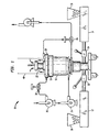
- Figure 1 is a schematic diagram illustrating an extrusion apparatus useful for manufacturing membranes in accordance with the present invention;
- Figure 2 is a detail of the apparatus of Figure 1 showing the operation of the quench of both sides of the cylindrical polymer film parison;
- Figure 3 is another more detailed schematic diagram illustrating operation of the inventive process.
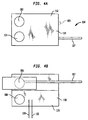
- Figures 4A and 4B are schematic diagrams of a test cell used to measure electrical resistance of a microporous battery separator as a function of temperature;
- Figure 5 is a plot of electrical resistance versus temperature for various commercially available membranes at a scan (heating) rate of 60°C per minute; and
- Figure 6 is a plot of electrical resistance versus temperature for membranes manufactured in accordance with the present invention as well as two other commercially available membranes.
-
- The invention is described in detail below with reference to numerous examples which are provided for purposes of illustration only. The spirit and scope of the present invention is defined in the appended claims.
- The preferred process by which the inventive separators are made broadly comprises the following steps: extruding a polymer film to form a sheet; annealing the sheet to enhance the crystal structure and stretching the annealed sheet. The following references, as well as the reference cited therein, illustrate the state of the art of the preferred process and are incorporated herein by reference: United States Patent No. 5,565,281 of Yu et al.; United States Patent No. 5,691,077 of Yu; and United States Patent No. 5,667,911 of Yu et al. Knowledge of these methods being readily available to those of skill in the art, the inventive process shall be described by explaining differences between the prior art and the inventive method for making battery separators in accordance with the invention.
- Broadly, process improvements which produce films in accordance with the present invention involve utilizing an apparatus which applies a quenching fluid, such as air, to both sides of the polymer sheet as illustrated in connection with Figures 1 and 2.
- There is shown in Figure 1 a schematic representation of an extrusion apparatus capable of co-extruding a multi-layer cylindrical parison. An
extrusion apparatus 10 includes generally afirst extruder 12 and asecond extruder 14 connected to adie assembly 16.Assembly 16 defines a cylindrical mandrel type of die orifice indicated at 18 as well as an outer air quenchring 20 and an inner quenchring apparatus 22, as shown in Figures 1 and 2. Cooling air is supplied by way of afan 24 to dieassembly 16 and inner quenchring apparatus 22. Anotherfan 26 supplies cooling air to the outer quenchring 20. A plurality ofvalves valves - In operation,
polymer pellets extruders valves assembly 16. One may choose to feed only one polymer to make it monolayer film if so desired by utilizing only one extruder, or employ more than two extruders to make multi-layer separators. In each case, a suitable die is configured to extrude one layer or co-extrude multiple layers. - Fully molten polymers are fed to die
assembly 16 and extruded throughorifice 18. Upon exit,cylindrical film parison 40 is molten as it meets the cooling air streams on both sides of the film, as is better illustrated in connection with Figure 2. - In Figure 2, like parts are indicated with the same numerals as in Figure 1. As
cylindrical film 40 exits orifice 18 it is molten and there is applied about its entire outer periphery an outer quenching air stream indicated at 42 and about its entire inner periphery another quenching air stream indicated at 44. Both air streams 42, 44, are low temperature air streams generally from about 0°C to about 45°C, with about 15-30°C being more typical. Air streams 42, 44 are operative to fully quench the melt phase offilm 40 such that it is in a substantially solidified state at 46. -
Apparatus 22 includes an exit suction orifice indicated at 48, so that the volume ofair stream 44 can exit a cavity 50 defined bycylindrical film 40 as is desired in order to control pressure. - There is shown in Figure 3 a more detailed quench
apparatus 60 utilized in connection with the examples which follow.Apparatus 60 includes adie exit 62 from which molten polymer exits the die to form acylindrical parison 64. There is also provided anouter air ring 66 and aninner air ring 68 to provide quenching air to both sides offilm parison 64. Air paths are thus defined as shown byarrows adjustable gap adjustable height die exit 62 as noted in the examples which follow. The gaps are adjusted along with the various pressures and valves to regulate air flow as desired. - A
blower 82 provides air toouter air ring 66 as shown and the pressure may be measured at 85, while anotherblower 86 provides air toinner ring 68 where the pressure is measured by a gauge at 87. Air flows to the inner ring as indicated byarrows - There is further provided an
exhaust blower 90 which is provided with acontrol valve 92 to control flow out of the interior ofcylindrical prison 64 as shown byarrows - In the foregoing manner, a quenching air stream is applied to both sides of a cylindrical prison as it exits a circular die to provide a double sided quench of the molten polymer as it exits the die.
Blowers - The film thickness of the parison is generally from about 0.2 to about 2 thousandths of an inch (mils). The
heights air gaps cylindrical prison 64 typically has a diameter of about 11.5 to about 12.5 inches; while the degree of expansion can be manipulated by way of the air flow and particularly by way ofvalve 92. - Following extrusion of the film as described above it is annealed, elongated and heat set as is further described in connection with the examples which follow. A series of multi-layer microporous battery separators were prepared as described in detail hereinafter. Product characteristics are reported in accordance with the following table:
Test Methods Gurley ASTM-D726(B) Gurley is a resistance to air flow measured by the Gurley densometer (e.g. Model 4120). Gurley is the time in seconds required to pass 10cc of air through one square inch of product under a pressure of 12.2 inches of water. Basis Weight Basis weight is determined by cutting three - one square foot samples across the width of the sample and weighing them on a precision balance with accuracy to 0.000 1 grams. The three (3) samples are averaged and compared to tolerance limits. Thickness Method: T411 om-83 developed under the auspices of the Technical Association of the Pulp and Paper Industry. Thickness is determined using a precision micrometer with a ½ inch diameter, circular shoe contacting the sample at seven (7) PSI. Ten (10) individual micrometer readings taken across the width of the sample are averaged. Shrinkage, MD ASTM D-1204 (60 min. @ 90°C.) Three separate lengths of stretched product of approximately ten centimeters are measured across the width of the sample in the machine direction (MD). The sample is exposed to air at 90°C. for one hour, the lengths are re-measured, the percentage shrinkage of the original length is calculated for each sample, and the results averaged. - A 1 mil in thickness polypropylene/polyethylene/polypropylene microporous battery separator was prepared utilizing the apparatus shown in Figures 1 and 2. The inner and outer quench rings were supplied with air at room temperature and were positioned slightly over 3 inches in height from the die exit. Extrusion conditions are given in Table 2. Following extrusion, the sheet was annealed, stretched in a two step process and heat set under the conditions of Table 3. Product characteristics appear in Table 4.
Summary of Materials and Extrusion Conditions for Battery Separator of Example 1 Equipment: . Alpine 3 layer Co-extrusion die; 210 mil Mandrel gap, 300 mm die diameter Resin: Fina (Dallas, TX) PP 3362 isotactic polypropylene, Mitsu Petroleum Chemical (Tokyo, JP) HIZEX® HDPE 5202B polyethylene Polypropylene Extruder Barrel Temperature: 195°C Polyethylene Extruder Barrel Temperature: 185°C Die Temperature: 185°C Line Speed: 105 ft/sec Quench Ring Height from Die Exit; inner, outer: 3 5/16 inches, 3 5/16 inches Quench Ring Air Pressure; inner, outer: 7.0 inches H2O, 7.0 inches H20 Quench Ring Gap; inner, outer (inches) 0.200 inches, 0.150 inches Summary of Annealing/Stretching Conditions for Battery Separator of Example 1 Annealing Temperature: 120°C Annealing Time: 15 minutes Cold Stretch Temperature: 25°C Cold Stretch Elongation: 25% Hot Stretch Temperature: 120°C Hot Stretch Elongation: 100% Heat Set Temperature: 120°C Average Product Characteristics for Battery Separator of Example 1 Gurley Secs Thickness mils Shrinkage % Base Weight mg/ cm2 Porosity % 26 0.9 3.5 1.26 37.2 - Following the procedure of Example 1, a bi-layer polyethylene/polypropylene microporous battery separator was prepared. Materials, equipment and extrusion conditions appear in Table 5, while annealing and stretching conditions appear in Table 6. Average product characteristics appear in Table 7.
Summary of Materials and Extrusion Conditions for Battery Separator of Example 2 equipment: Alpine two layer co-extrusion Die, 210 mil mandrel gap, 300 mm die diameter resin: Fina PP 3271 isotactic polypropylene, HIZEX®5202B high density polyethylene Polypropylene Extruder Barrel Temperature: 200°C Polyethylene Extruder Barrel Temperature: 190°C Die Temperature: 200°C Line Speed: 100 ft/minute Quench Ring Height from Die Exit; inner, outer: 3 inches, 3 5/16 inches Quench Ring Air Pressure: inner, outer: 4 inches H2O, 8 inches H2O Quench Ring Gap; inner, outer: 0.200 inches, 0.150 inches Summary of Annealing/Stretching Conditions for Battery Separator of Example 2 Annealing Temperature: 120°C Annealing Time: 12 minutes Cold Stretch Temperature: 25°C Cold Stretch Elongation: 25% Hot Stretch Temperature: 120° Hot Stretch Elongation: 130% Heat Set Temperature: 120° Average Product Characteristics for Battery Separator of Example 2 Gurley Sec Thickness mils Shrinkage % Base Weight mg/cm2 Porosity % 25 1.0 4.5 1.32 43.0 - Following the procedure of Example 1, another polypropylene/polyethylene/polypropylene tri-layer battery separator was prepared in accordance with the present invention. A summary of the materials and extrusion conditions appear in Table 8. Annealing, stretching and heat setting conditions are given in Table 9, while Table 10 sets forth product characteristics.
Summary of Materials and Extrusion Conditions for Battery Separator of Example 3 Equipment: Alpine 3 layer co-extrusion die, 210 mil mandrel gap, 300 mm die diameter Resin: Fina 3271 isotactic polypropylene, HIZEX® HDPE 5202B high density polyethylene Polypropylene Extruder Barrel Temperature: 190°C Polyethylene Extruder Barrel Temperature: 185°C Die Temperature: 200°C Line Speed: 85 ft/sec. Quench Ring Height from Die Exit; inner, outer: 3 13/16 inches, 3 1/2 inches Quench Ring Air Pressure; inner, outer: 4 inches H2O; 4 inches H2O Quench Ring Gap; inner, outer: 0.250, 0.100 Summary of Annealing/Stretching Conditions for Battery Separator of Example 3 Annealing Temperature: 122°C Annealing Time: 12 minutes Cold Stretch Temperature: 25°C Cold Stretch Elongation: 45% Hot Stretch Temperature: 122° Hot Stretch Elongation: 120% Heat Set Temperature: 122°C Average Product Characteristics for Battery Separator of Example 3 Gurley sec Thickness mils Shrinkage 5 Base Weight mg/ cm2 Porosity % 30 0.86 2.1 1.25 37 - A polyethylene/polypropylene/polyethylene tri-layer battery separator was prepared in according to the Example 1 above. Extrusion particulars appear in Table 11, along with the equipment and materials employed. Annealing, stretching and heat setting conditions are given in Table 12, while representative product characteristics appear in Table 13.
Summary of Materials and Extrusion Conditions For Battery Separator of Example 4 Equipment: Alpine Three layer co-extrusion Die; 140 mil gap/300 mm die diameter Resin: Fina, 3271 isotactic polypropylene; HIZEX® 5202B high density polyethylene Polypropylene Extruder Barrel Temperature: 195°C Polyethylene Extruder Barrel Temperature: 185°C Die Temperature: 200°C Line Speed: 80 ft/min Quench Ring Height from Die Exit; inner, outer: 2 3/4 inches, 3 5 /16 inches Quench Ring Air Pressure; inner, outer: 4 inches, 7 inches H2O Quench Ring Air Gap; inner, outer: 0.150 inches, 0.200 inches Summary of Annealing/Stretching Conditions for the Battery Separator of Example 4 Annealing Temperature: 120°C Annealing Time: 12 minutes Cold Stretch Temperature: 25°C Cold Stretch Elongation: 25% Hot Stretch Temperature: 120° Hot Stretch Elongation: 130% Heat Set Temperature: 120° Average Product Characteristics for Battery Separator of Example 4 Gurley Sec Thickness mils Shrinkage % Base Weight mg/cm2 Porosity % 33 1.07 3 1.4 41 - Another polyethylene/polypropylene/polyethylene tri-layer battery separator was prepared in accordance wit Example 4. Materials, equipment and extrusion conditions are listed in Table 14. Table 15 gives annealing, heat treating and stretching conditions, while Table 16 lists available product characteristics.
Summary of Materials and Extrusion Conditions for Battery Separator Example 5 Equipment: Alpine 3 layer co-extrusion die; 140 mil mandrel gap, 300 mm die diameter Resin: Fina 3271 isotactic polypropylene HIZEX® 5202B high density polyethylene Polypropylene Extruder Barrel Temperature: 195°C Polyethylene Extruder Barrel Temperature: 190°C Die Temperature: 193°C Line Speed: 90 ft/min. Quench Ring Height from Die Exit; inner, outer: 3 ½ inches, 3 5/16 inches Quench Ring Air Pressure; inner, outer: 4 inches H2O, 6 inches H2O Quench Ring Gap; inner, outer: 0.200 inches, 0.080 inches Summary of Annealing/Stretching Conditions for Battery Separator of Example 5 Annealing Temperature: 120°C Annealing Time: 12 minutes Cold Stretch Temperature: 25° Cold Stretch Elongation: 25% Hot Stretch Temperature: 120° Hot Stretch Elongation: 130% Heat Set Temperature: 120°C Average Product Characteristics for Battery Separator of Example 5 Gurley Sec Thickness mils Shrinkage % Base Weight mg/cm2 Porosity % 17 0.50 -- -- -- - Following the procedure of Example 1, another polypropylene/polyethylene/polypropylene tri-layer battery separator was prepared in accordance with the invention. Particulars as to equipment, materials, and extrusion conditions appear in Table 17. Table 18 lists annealing, stretching and heat setting parameters. Table 19 lists product characteristics.
Summary of Materials and Extrusion Conditions for Battery Separator of Example 6 Equipment: Alpine 3 layer co-extrusion die, 140 mil mandrel gap, 300 mm die diameter Resin: Fina 3271 isotatic polypropylene, HIZEX® 5202B high density polyethylene Polypropylene Extruder Barrel Temperature: 195°C Polyethylene Extruder Barrel Temperature: 185°C Die Temperature: 198°C Line Speed: 80 ft/min Quench Ring Height from Die Exit; inner, outer: 3 inches, 3 5/16 inches Quench Ring Air Pressure; inner, outer: 2 inches H2O, 3 inches H2O Quench Ring Gap; inner, outer: 0.080 inches, 0.200 inches Summary of Annealing/Stretching Conditions for Battery Separator of Example 6 Annealing Temperature: 125°C Annealing Time: 8 minutes Cold Stretch Temperature: 25°C Cold Stretch Elongation: 45% Hot Stretch Temperature: 118°C Hot Stretch Elongation: 200% Heat Set Temperature: 125°C Average Product Characteristics for Battery Separator of Example 6 Gurley Sec Thickness mils Shrinkage % Base Weight mg/ cm2 Porosity % 24 15 8 0.70 48 - Despite the industry interest in shut down or fusible battery separators, there has been little work done on characterizing the phenomena involved. It is believed that in a thermal runaway situation in a battery, the temperature may rise at 100°C per minute or more, perhaps multiples of such a heating rate. It is believed desirable for battery separators to exhibit large increases in electrical resistance at 120-130°C and maintain such high resistance, say 10,000 ohms per square centimeter or so, as long as possible. Polypropylene/polyethylene membranes have been employed wherein polyethylene melts at a lower temperature so as to block the microporous structure, while the polypropylene maintains it structure to a higher temperature. Figures 4A and 4B illustrate a measurement cell useful for characterizing the electrical properties of a battery separator versus temperature.
Cell 100 includes four 0.375 inchdiameter nickel disks -
Top assembly 114 andbottom assembly 116 are used to sandwich a separator by placing the separator there between and pressing the electrodes in a Carver press at a 125 psi with heated platens. The platens were heated at a constant rate from 60°C to 200°C using a Eurotherm® model 808 controller. The temperature of the electrode surface was sensed by two type E thermocouples indicated at 118, 120 (0.5 mil thick, not shown) which were located between a pair of electrodes positioned adjacent to the electrodes holding the separator. - The apparatus of Figures of 4A and 4B is operated as described by Geiger et. al., "Advanced Separators for Lithium Batteries", 11th International Seminar on Primary and Secondary Battery Technology and Application, Feb. 28-Mar. 3, 1994. An electrolyte consisting of 1M lithium trifluoromethanane- sulfonimide (HQ-115, 3M3 Co.) in a 1:1 by volume solution of propylene carbonate (Aldrich), and triethylene glycol dimethyl ether (Aldrich) was used. The conductivity of this electrolyte does not vary significantly over the temperature range employed. Electrical resistance measurements were made using an RLC bridge (GenRad Model 1659) at 1 KHZ as described by Laman et. al., "Impedance Studies for Separators in Rechargeable Lithium Batteries", J. Electrochem. Soc., Vol. 140, No. 4, April, 1993, pp. L51-53.
- Figure 5 shows typical electrical resistance curves versus temperature for commercially available battery separators measured as above at a heating rate or scan rate of 60°C per minute. Separator A is a polypropylene battery separator, Separator B is a polyethylene battery separator and Separator C is a polypropylene/polyethylene/polypropylene tri-layer separator. Separator C was also tested at a scan rate of 1° per minute and it was found that the high resistance exhibited above 130°C or so exhibited a slightly lower upper temperature limit.
- Figure 6 shows electrical properties of five different separators measured as described above at scan rates of 60°C per minute. Separators 6(a), 6(b), and 6(c) were polyethylene/polypropylene/polyethylene membranes prepared in accordance with Example 5. Separator D was a polypropylene/polyethylene/ polypropylene commercially available separator, while Separator E was a commercially available high molecular weight polyethylene separator.
- It can be seen from Figure 6 that only the membranes in accordance with the invention exhibit electrical resistance greater than 10,000 ohms per square centimeters between 130°C and 185°C. This characteristic is unique to the separators of the present invention which is further defined in the appended claims.
Claims (20)
- A battery separator comprising a microporous polyolefinic membrane capable of maintaining an electrical resistance greater than about 10,000 ohms per square centimeter at a temperature of at least about 185°C as measured at a scan rate of 60°C per minute.
- The battery separator according to Claim 1, wherein said polyolefinic membrane is capable of maintaining an electrical resistance greater than about 10,000 ohms per square centimeter at a temperature of at least about 185°C as measured as a scan rate of 2°C per minute.
- The battery separator according to Claim 1, wherein said polyolefinic membrane is characterized by maintaining an electrical resistance greater than about 10,000 ohms per square centimeter over a temperature range of from about 130°C to about 185°C as measured at a scan rate of 60°C per minute.
- The battery separator according to Claim 2, wherein said polyolefinic membrane is characterized by maintaining an electrical resistance greater than about 10,000 ohms per square centimeter over a temperature range of from about 130°C to about 185°C as measured at a scan rate of 2°C per minute.
- The battery separator according to Claim 1 wherein said polyolefinic membrane is formed of a polymer selected from the group consisting of polyethylene, polypropylene and mixtures thereof.
- The battery separator according to Claim 5 wherein said polyolefinic membrane comprises a microporous polyolefinic formed of isotactic polypropylene.
- The battery separator according to Claim 5 wherein said polyolefinic membrane comprises a microporous membrane formed of high density polyethylene.
- The battery separator according to Claim 1 wherein said polyolefinic membrane is a multilayer polyolefinic membrane including at least one layer formed of polypropylene and at least one layer formed of polyethylene.
- The battery separator according to Claim 8, wherein said polyolefinic membrane is a bi-layer membrane.
- The battery separator according to Claim 8, wherein said membrane is a polypropylene-polyethylene-polypropylene tri-layer membrane.
- A method of making a battery separator comprising:(a) extruding a cylindrical parison of a polymer film in a molten state having inner and outer surfaces;(b) applying a low temperature fluid stream to said inner and outer surfaces of said cylindrical prison, said low temperature fluid stream being operative to quench said molten polymer film on both surfaces such that it is in a substantially solidified state; and(c) imparting porosity to said polymer film to make said microporous separator.
- The method according to Claim 11, wherein said method of extruding said polymer film includes co-extruding a polymer film with at least 2 layers of different composition.
- The method according to Claim 12, wherein said polymer film includes a polyethylene layer and a polypropylene layer.
- The method according to Claim 13, wherein said polyethylene layer is formed of high density polyethylene and said polypropylene layer is formed of isotactic polypropylene.
- A method of making a battery separator comprising:(a) extruding a cylindrical prison of a polymer film in a molten state having inner and outer surfaces;(b) applying a low temperature fluid stream to said inner and outer surfaces of said polymer film, said low temperature fluid stream being operative to quench said molten polymer film on both surfaces such that it is in a substantially solidified state;(c) annealing said polymer film to enhance its crystalline structure;(d) elongating said film; and(e) heat setting said film.
- The method according to Claim 15, wherein said step of elongating said film comprises:(f) elongating said film by at least about 20 per cent at a low temperature followed by;(g) elongating said film at an elevated temperature by at least about 100 per cent.
- 17. The method according to claim 16, wherein said low temperature is from about 15 to about 35°C.
- The method according to Claim 16, wherein said high temperature is from about 110°C to about 135°C.
- The method according to Claim 15, wherein said polymer film includes a polyethylene layer and a polypropylene layer.
- The method according to Claim 19, wherein said polypropylene layer is formed of isotactic polypropylene.
Applications Claiming Priority (2)
| Application Number | Priority Date | Filing Date | Title |
|---|---|---|---|
| US09/296,682 US6346350B1 (en) | 1999-04-20 | 1999-04-20 | Structurally stable fusible battery separators and method of making same |
| US296682 | 1999-04-20 |
Publications (1)
| Publication Number | Publication Date |
|---|---|
| EP1047141A2 true EP1047141A2 (en) | 2000-10-25 |
Family
ID=23143080
Family Applications (1)
| Application Number | Title | Priority Date | Filing Date |
|---|---|---|---|
| EP20000108315 Withdrawn EP1047141A2 (en) | 1999-04-20 | 2000-04-15 | Structurally stable, fusible battery separators and method of making same |
Country Status (7)
| Country | Link |
|---|---|
| US (1) | US6346350B1 (en) |
| EP (1) | EP1047141A2 (en) |
| JP (1) | JP2000340207A (en) |
| KR (1) | KR20000071722A (en) |
| CN (1) | CN1271184A (en) |
| CA (1) | CA2301453A1 (en) |
| SG (1) | SG97881A1 (en) |
Cited By (8)
| Publication number | Priority date | Publication date | Assignee | Title |
|---|---|---|---|---|
| EP1348540A1 (en) * | 2002-03-27 | 2003-10-01 | Celgard Inc. | Multilayer battery separators |
| WO2006069307A3 (en) * | 2004-12-22 | 2006-08-17 | Entegris Inc | Multilayer porous membrane and process of manufacture |
| WO2009132802A3 (en) * | 2008-05-02 | 2010-01-28 | Treofan Germany Gmbh & Co. Kg | Micro-porous multi-layer membrane film based on polypropylene for batteries with a cut-off function |
| WO2011086823A1 (en) * | 2010-01-13 | 2011-07-21 | Toray Tonen Specialty Separator Godo Kaisha | Microporous membranes and methods for producing and using such membranes |
| EP2089922A4 (en) * | 2006-11-17 | 2011-08-10 | Celgard Llc | CO-EXTRUDED MULTILAYER SEPARATOR |
| EP1930156A4 (en) * | 2005-09-28 | 2011-11-23 | Toray Tonen Specialty Separato | Process for producing microporous polyethylene film and separator for cell |
| US8551610B2 (en) | 2008-05-02 | 2013-10-08 | Treofan Germany Gmbh & Co. Kg | Single-layer polypropylene membrane film for batteries, having a shut-off function |
| US9067392B2 (en) | 2008-05-02 | 2015-06-30 | Treofan Germany Gmbh & Co. Kg | Membrane file for batteries, having a shut-off function |
Families Citing this family (24)
| Publication number | Priority date | Publication date | Assignee | Title |
|---|---|---|---|---|
| US6432586B1 (en) | 2000-04-10 | 2002-08-13 | Celgard Inc. | Separator for a high energy rechargeable lithium battery |
| US8007940B2 (en) * | 2001-12-11 | 2011-08-30 | Eveready Battery Company, Inc. | High discharge capacity lithium battery |
| US20050112462A1 (en) * | 2003-11-21 | 2005-05-26 | Marple Jack W. | High discharge capacity lithium battery |
| US6796554B2 (en) * | 2002-09-13 | 2004-09-28 | Hewlett-Packard Development Company, L.P. | Apparatus for stacking folded paper sheets |
| US7501008B2 (en) * | 2003-01-31 | 2009-03-10 | Microcell Corporation | Hydrogen storage systems and fuel cell systems with hydrogen storage capacity |
| US20050031943A1 (en) * | 2003-08-07 | 2005-02-10 | Call Ronald W. | Battery separator and method of making same |
| US20050233214A1 (en) * | 2003-11-21 | 2005-10-20 | Marple Jack W | High discharge capacity lithium battery |
| US8283071B2 (en) | 2003-11-21 | 2012-10-09 | Eveready Battery Company, Inc. | High discharge capacity lithium battery |
| US8124274B2 (en) * | 2003-11-21 | 2012-02-28 | Eveready Battery Company, Inc. | High discharge capacity lithium battery |
| US20050244717A1 (en) * | 2004-04-30 | 2005-11-03 | Celgard Inc. | Battery separator with antistatic properties |
| CN101228650B (en) * | 2005-07-25 | 2010-12-08 | 帝人株式会社 | Separator for non-aqueous secondary battery and manufacturing method thereof |
| WO2007046473A1 (en) * | 2005-10-19 | 2007-04-26 | Tonen Chemical Corporation | Process for producing multilayered microporous polyolefin film |
| PT103380B (en) * | 2005-11-09 | 2007-09-13 | Univ Do Minho | LINE OF EXTRUSION LABORATORIAL FOR THE PRODUCTION OF TUBULAR FILM CONVENTIONAL AND BIORIENTED, WITH SIMPLE SWITCHING BETWEEN THE TWO TECHNIQUES |
| CN101641406B (en) * | 2007-01-19 | 2012-12-26 | 东丽电池隔膜株式会社 | Polymeric material and its manufacture and use |
| JP4801705B2 (en) * | 2008-09-03 | 2011-10-26 | 三菱樹脂株式会社 | Laminated porous film for separator and method for producing the same |
| JP5519682B2 (en) * | 2008-10-24 | 2014-06-11 | 東レバッテリーセパレータフィルム株式会社 | Multilayer microporous membranes and methods for making and using such membranes |
| CN102820444B (en) * | 2011-06-10 | 2015-09-30 | 比亚迪股份有限公司 | A kind of battery diaphragm and preparation method thereof |
| KR101295525B1 (en) * | 2011-06-17 | 2013-08-12 | (주)이쎌텍 | Apparatus and Method for manufacturing microporous film for a separator of battery |
| JP5883379B2 (en) * | 2011-09-08 | 2016-03-15 | 日新製鋼株式会社 | Battery exterior laminate, method for producing the same, and secondary battery |
| CN103035864B (en) * | 2011-09-30 | 2017-06-06 | 天津东皋膜技术有限公司 | With the resistant to elevated temperatures coated separator of elasticity of compression Thermal shutdown |
| CN102700222B (en) * | 2012-05-02 | 2015-07-01 | 达尼特材料科技(芜湖)有限公司 | Porous film and manufacturing method thereof |
| CN103128975B (en) * | 2012-12-28 | 2014-10-15 | 深圳中兴创新材料技术有限公司 | Preparation method of polypropylene microporous membrane, polypropylene microporous membrane and application of polypropylene microporous membrane |
| KR20180026790A (en) * | 2015-07-31 | 2018-03-13 | 셀가드 엘엘씨 | Improved laminated multilayer film, separator, battery, and method |
| PL3350854T3 (en) * | 2015-09-18 | 2023-01-30 | Celgard, Llc | Improved membranes, calendered microporous membranes, battery separators and related methods |
Family Cites Families (27)
| Publication number | Priority date | Publication date | Assignee | Title |
|---|---|---|---|---|
| US3679538A (en) * | 1970-10-28 | 1972-07-25 | Celanese Corp | Novel open-celled microporous film |
| CA1028440A (en) * | 1973-02-26 | 1978-03-21 | Uop Inc. | Polymer compositions with treated filler |
| EP0099228A3 (en) * | 1982-07-06 | 1985-05-15 | Exxon Research And Engineering Company | Electrosensitive transfer film |
| US4539256A (en) * | 1982-09-09 | 1985-09-03 | Minnesota Mining And Manufacturing Co. | Microporous sheet material, method of making and articles made therewith |
| US4436888A (en) * | 1982-10-05 | 1984-03-13 | E. I. Du Pont De Nemours And Company | Method for making balanced low shrink tension polyolefin film |
| US4634739A (en) * | 1984-12-27 | 1987-01-06 | E. I. Du Pont De Nemours And Company | Blend of polyethylene and polypropylene |
| US4650730A (en) * | 1985-05-16 | 1987-03-17 | W. R. Grace & Co. | Battery separator |
| US4882466A (en) * | 1988-05-03 | 1989-11-21 | Raychem Corporation | Electrical devices comprising conductive polymers |
| JP2642206B2 (en) | 1989-12-28 | 1997-08-20 | 旭化成工業株式会社 | Explosion-proof secondary battery |
| US5851610A (en) * | 1991-02-07 | 1998-12-22 | Applied Extrusion Technologies, Inc. | Shrink films and articles including the same |
| JPH0698395A (en) | 1991-09-30 | 1994-04-08 | Iwatsu Electric Co Ltd | Sound source diaphragm |
| US5281491A (en) | 1991-12-20 | 1994-01-25 | W. R. Grace & Co. | Battery separator |
| US5240655A (en) | 1991-12-20 | 1993-08-31 | W. R. Grace & Co.-Conn. | Process of making a battery separator |
| JPH0698394A (en) | 1992-09-11 | 1994-04-08 | Pioneer Cone Corp | Production of speaker vibrating parts |
| JP3352801B2 (en) | 1994-01-31 | 2002-12-03 | 日東電工株式会社 | Porous film, its production method and its use |
| US5667911A (en) * | 1994-11-17 | 1997-09-16 | Hoechst Celanese Corporation | Methods of making cross-ply microporous membrane battery separator, and the battery separators made thereby |
| US5565281A (en) | 1994-12-02 | 1996-10-15 | Hoechst Celanese Corporation | Shutdown, bilayer battery separator |
| TW297171B (en) * | 1994-12-20 | 1997-02-01 | Hoechst Celanese Corp | |
| JPH08250097A (en) | 1995-03-15 | 1996-09-27 | Kureha Chem Ind Co Ltd | Interpole separator for electrochemical device |
| JPH08244152A (en) * | 1995-03-15 | 1996-09-24 | Nitto Denko Corp | Porous film and method for producing the same |
| JPH08266398A (en) | 1995-03-30 | 1996-10-15 | Nippon Sanso Kk | Insulated cooking pot |
| JP3508295B2 (en) | 1995-04-24 | 2004-03-22 | カシオ計算機株式会社 | Method for manufacturing thin film transistor |
| JP3203160B2 (en) | 1995-08-09 | 2001-08-27 | 三菱電機株式会社 | Volume rendering apparatus and method |
| JP3939778B2 (en) * | 1996-02-09 | 2007-07-04 | 日東電工株式会社 | Battery separator |
| JPH10154499A (en) * | 1996-11-22 | 1998-06-09 | Nitto Denko Corp | Battery separator and non-aqueous secondary battery using the same |
| US5993954A (en) * | 1997-04-29 | 1999-11-30 | 3M Innovative Properties Company | Temperature-sensitive microporous film |
| US5888640A (en) * | 1997-07-09 | 1999-03-30 | Mobil Oil Corporation | Metallized uniaxially shrinkable biaxially oriented polypropylene film |
-
1999
- 1999-04-20 US US09/296,682 patent/US6346350B1/en not_active Expired - Lifetime
-
2000
- 2000-03-21 CA CA002301453A patent/CA2301453A1/en not_active Abandoned
- 2000-04-04 SG SG200001906A patent/SG97881A1/en unknown
- 2000-04-15 EP EP20000108315 patent/EP1047141A2/en not_active Withdrawn
- 2000-04-18 KR KR1020000020321A patent/KR20000071722A/en not_active Ceased
- 2000-04-19 CN CN00106839A patent/CN1271184A/en active Pending
- 2000-04-20 JP JP2000119291A patent/JP2000340207A/en active Pending
Cited By (16)
| Publication number | Priority date | Publication date | Assignee | Title |
|---|---|---|---|---|
| CN1300862C (en) * | 2002-03-27 | 2007-02-14 | 思凯德公司 | Multilayer battery diaphragm |
| EP1348540A1 (en) * | 2002-03-27 | 2003-10-01 | Celgard Inc. | Multilayer battery separators |
| US8758887B2 (en) | 2004-12-22 | 2014-06-24 | Entegris, Inc. | Multilayer porous membrane and process |
| WO2006069307A3 (en) * | 2004-12-22 | 2006-08-17 | Entegris Inc | Multilayer porous membrane and process of manufacture |
| EP1930156A4 (en) * | 2005-09-28 | 2011-11-23 | Toray Tonen Specialty Separato | Process for producing microporous polyethylene film and separator for cell |
| US10818899B2 (en) | 2006-11-17 | 2020-10-27 | Celgard, Llc | Co-extruded, multi-layered battery separator |
| US10003058B2 (en) | 2006-11-17 | 2018-06-19 | Celgard, Llc | Method of making a co-extruded, multi-layered battery separator |
| EP2089922A4 (en) * | 2006-11-17 | 2011-08-10 | Celgard Llc | CO-EXTRUDED MULTILAYER SEPARATOR |
| US9067392B2 (en) | 2008-05-02 | 2015-06-30 | Treofan Germany Gmbh & Co. Kg | Membrane file for batteries, having a shut-off function |
| US8551610B2 (en) | 2008-05-02 | 2013-10-08 | Treofan Germany Gmbh & Co. Kg | Single-layer polypropylene membrane film for batteries, having a shut-off function |
| US8906540B2 (en) | 2008-05-02 | 2014-12-09 | Treofan Germany Gmbh & Co. Kg | Micro-porous multi-layer membrane film based on polypropylene for batteries with a cut-off function |
| WO2009132802A3 (en) * | 2008-05-02 | 2010-01-28 | Treofan Germany Gmbh & Co. Kg | Micro-porous multi-layer membrane film based on polypropylene for batteries with a cut-off function |
| US9044716B2 (en) | 2010-01-13 | 2015-06-02 | Toray Battery Separator Film Co., Ltd. | Microporous membranes and methods for producing and using such membranes |
| CN102740956A (en) * | 2010-01-13 | 2012-10-17 | 东丽电池隔膜合同会社 | Microporous membranes and methods for producing and using such membranes |
| CN102740956B (en) * | 2010-01-13 | 2015-11-25 | 东丽电池隔膜株式会社 | Microporosity film and the method for the preparation of the film such with use |
| WO2011086823A1 (en) * | 2010-01-13 | 2011-07-21 | Toray Tonen Specialty Separator Godo Kaisha | Microporous membranes and methods for producing and using such membranes |
Also Published As
| Publication number | Publication date |
|---|---|
| CN1271184A (en) | 2000-10-25 |
| JP2000340207A (en) | 2000-12-08 |
| KR20000071722A (en) | 2000-11-25 |
| CA2301453A1 (en) | 2000-10-20 |
| SG97881A1 (en) | 2003-08-20 |
| US6346350B1 (en) | 2002-02-12 |
Similar Documents
| Publication | Publication Date | Title |
|---|---|---|
| US6346350B1 (en) | Structurally stable fusible battery separators and method of making same | |
| KR100699120B1 (en) | Battery Separator with Reduced Cleavage | |
| TWI425045B (en) | Multilayer microporous polyolefin film, preparation method thereof, and battery separator prepared therefrom | |
| KR100554637B1 (en) | Multilayer battery separator | |
| CN110815763B (en) | Apparatus and method for preparing high-strength high-modulus polyolefin film and high-strength high-modulus polyolefin film | |
| KR100512540B1 (en) | Manufacturing method of three-layer battery separator | |
| TWI413657B (en) | Polyolefin multi-layered micro-porous film, method of manufacturing the same, separator for battery and battery | |
| KR101404451B1 (en) | Multilayer polyolefin-based microporous membrane and method for manufacturing the same | |
| EP2660277A1 (en) | Polyolefin porous membrane and method of producing the same | |
| JP4516796B2 (en) | Battery separator and manufacturing method thereof | |
| JP7047382B2 (en) | Polyolefin microporous membrane, lithium ion secondary battery and polyolefin microporous membrane manufacturing method | |
| EP0715364A1 (en) | Shutdown, bilayer battery separator | |
| JPH05251070A (en) | Manufacture of separator for battery | |
| JPWO2018043335A1 (en) | Microporous membrane, lithium ion secondary battery and method of producing microporous membrane | |
| KR101452945B1 (en) | Microporous polyolefin multi layer film and preparing method thereof | |
| EP0924780B1 (en) | Penta-layer battery separator | |
| JP2025183380A (en) | Manufacturing method of multilayer separator |
Legal Events
| Date | Code | Title | Description |
|---|---|---|---|
| PUAI | Public reference made under article 153(3) epc to a published international application that has entered the european phase |
Free format text: ORIGINAL CODE: 0009012 |
|
| AK | Designated contracting states |
Kind code of ref document: A2 Designated state(s): AT BE CH CY DE DK ES FI FR GB GR IE IT LI LU MC NL PT SE |
|
| AX | Request for extension of the european patent |
Free format text: AL;LT;LV;MK;RO;SI |
|
| STAA | Information on the status of an ep patent application or granted ep patent |
Free format text: STATUS: THE APPLICATION HAS BEEN WITHDRAWN |
|
| 18W | Application withdrawn |
Effective date: 20060216 |