EP0924780B1 - Penta-layer battery separator - Google Patents
Penta-layer battery separator Download PDFInfo
- Publication number
- EP0924780B1 EP0924780B1 EP98123315A EP98123315A EP0924780B1 EP 0924780 B1 EP0924780 B1 EP 0924780B1 EP 98123315 A EP98123315 A EP 98123315A EP 98123315 A EP98123315 A EP 98123315A EP 0924780 B1 EP0924780 B1 EP 0924780B1
- Authority
- EP
- European Patent Office
- Prior art keywords
- penta
- membranes
- separator
- layer
- polypropylene
- Prior art date
- Legal status (The legal status is an assumption and is not a legal conclusion. Google has not performed a legal analysis and makes no representation as to the accuracy of the status listed.)
- Expired - Lifetime
Links
Images
Classifications
-
- H—ELECTRICITY
- H01—ELECTRIC ELEMENTS
- H01M—PROCESSES OR MEANS, e.g. BATTERIES, FOR THE DIRECT CONVERSION OF CHEMICAL ENERGY INTO ELECTRICAL ENERGY
- H01M50/00—Constructional details or processes of manufacture of the non-active parts of electrochemical cells other than fuel cells, e.g. hybrid cells
- H01M50/40—Separators; Membranes; Diaphragms; Spacing elements inside cells
- H01M50/409—Separators, membranes or diaphragms characterised by the material
- H01M50/449—Separators, membranes or diaphragms characterised by the material having a layered structure
-
- B—PERFORMING OPERATIONS; TRANSPORTING
- B32—LAYERED PRODUCTS
- B32B—LAYERED PRODUCTS, i.e. PRODUCTS BUILT-UP OF STRATA OF FLAT OR NON-FLAT, e.g. CELLULAR OR HONEYCOMB, FORM
- B32B27/00—Layered products comprising a layer of synthetic resin
- B32B27/06—Layered products comprising a layer of synthetic resin as the main or only constituent of a layer, which is next to another layer of the same or of a different material
- B32B27/08—Layered products comprising a layer of synthetic resin as the main or only constituent of a layer, which is next to another layer of the same or of a different material of synthetic resin
-
- B—PERFORMING OPERATIONS; TRANSPORTING
- B32—LAYERED PRODUCTS
- B32B—LAYERED PRODUCTS, i.e. PRODUCTS BUILT-UP OF STRATA OF FLAT OR NON-FLAT, e.g. CELLULAR OR HONEYCOMB, FORM
- B32B27/00—Layered products comprising a layer of synthetic resin
- B32B27/32—Layered products comprising a layer of synthetic resin comprising polyolefins
-
- B—PERFORMING OPERATIONS; TRANSPORTING
- B32—LAYERED PRODUCTS
- B32B—LAYERED PRODUCTS, i.e. PRODUCTS BUILT-UP OF STRATA OF FLAT OR NON-FLAT, e.g. CELLULAR OR HONEYCOMB, FORM
- B32B37/00—Methods or apparatus for laminating, e.g. by curing or by ultrasonic bonding
- B32B37/14—Methods or apparatus for laminating, e.g. by curing or by ultrasonic bonding characterised by the properties of the layers
- B32B37/15—Methods or apparatus for laminating, e.g. by curing or by ultrasonic bonding characterised by the properties of the layers with at least one layer being manufactured and immediately laminated before reaching its stable state, e.g. in which a layer is extruded and laminated while in semi-molten state
- B32B37/153—Methods or apparatus for laminating, e.g. by curing or by ultrasonic bonding characterised by the properties of the layers with at least one layer being manufactured and immediately laminated before reaching its stable state, e.g. in which a layer is extruded and laminated while in semi-molten state at least one layer is extruded and immediately laminated while in semi-molten state
-
- B—PERFORMING OPERATIONS; TRANSPORTING
- B32—LAYERED PRODUCTS
- B32B—LAYERED PRODUCTS, i.e. PRODUCTS BUILT-UP OF STRATA OF FLAT OR NON-FLAT, e.g. CELLULAR OR HONEYCOMB, FORM
- B32B38/00—Ancillary operations in connection with laminating processes
- B32B38/0036—Heat treatment
-
- H—ELECTRICITY
- H01—ELECTRIC ELEMENTS
- H01M—PROCESSES OR MEANS, e.g. BATTERIES, FOR THE DIRECT CONVERSION OF CHEMICAL ENERGY INTO ELECTRICAL ENERGY
- H01M50/00—Constructional details or processes of manufacture of the non-active parts of electrochemical cells other than fuel cells, e.g. hybrid cells
- H01M50/40—Separators; Membranes; Diaphragms; Spacing elements inside cells
- H01M50/409—Separators, membranes or diaphragms characterised by the material
- H01M50/411—Organic material
- H01M50/414—Synthetic resins, e.g. thermoplastics or thermosetting resins
- H01M50/417—Polyolefins
-
- H—ELECTRICITY
- H01—ELECTRIC ELEMENTS
- H01M—PROCESSES OR MEANS, e.g. BATTERIES, FOR THE DIRECT CONVERSION OF CHEMICAL ENERGY INTO ELECTRICAL ENERGY
- H01M50/00—Constructional details or processes of manufacture of the non-active parts of electrochemical cells other than fuel cells, e.g. hybrid cells
- H01M50/40—Separators; Membranes; Diaphragms; Spacing elements inside cells
- H01M50/409—Separators, membranes or diaphragms characterised by the material
- H01M50/449—Separators, membranes or diaphragms characterised by the material having a layered structure
- H01M50/457—Separators, membranes or diaphragms characterised by the material having a layered structure comprising three or more layers
-
- H—ELECTRICITY
- H01—ELECTRIC ELEMENTS
- H01M—PROCESSES OR MEANS, e.g. BATTERIES, FOR THE DIRECT CONVERSION OF CHEMICAL ENERGY INTO ELECTRICAL ENERGY
- H01M50/00—Constructional details or processes of manufacture of the non-active parts of electrochemical cells other than fuel cells, e.g. hybrid cells
- H01M50/40—Separators; Membranes; Diaphragms; Spacing elements inside cells
- H01M50/489—Separators, membranes, diaphragms or spacing elements inside the cells, characterised by their physical properties, e.g. swelling degree, hydrophilicity or shut down properties
-
- B—PERFORMING OPERATIONS; TRANSPORTING
- B32—LAYERED PRODUCTS
- B32B—LAYERED PRODUCTS, i.e. PRODUCTS BUILT-UP OF STRATA OF FLAT OR NON-FLAT, e.g. CELLULAR OR HONEYCOMB, FORM
- B32B38/00—Ancillary operations in connection with laminating processes
- B32B38/0012—Mechanical treatment, e.g. roughening, deforming, stretching
- B32B2038/0028—Stretching, elongating
-
- B—PERFORMING OPERATIONS; TRANSPORTING
- B32—LAYERED PRODUCTS
- B32B—LAYERED PRODUCTS, i.e. PRODUCTS BUILT-UP OF STRATA OF FLAT OR NON-FLAT, e.g. CELLULAR OR HONEYCOMB, FORM
- B32B2323/00—Polyalkenes
- B32B2323/04—Polyethylene
-
- B—PERFORMING OPERATIONS; TRANSPORTING
- B32—LAYERED PRODUCTS
- B32B—LAYERED PRODUCTS, i.e. PRODUCTS BUILT-UP OF STRATA OF FLAT OR NON-FLAT, e.g. CELLULAR OR HONEYCOMB, FORM
- B32B2323/00—Polyalkenes
- B32B2323/10—Polypropylene
-
- B—PERFORMING OPERATIONS; TRANSPORTING
- B32—LAYERED PRODUCTS
- B32B—LAYERED PRODUCTS, i.e. PRODUCTS BUILT-UP OF STRATA OF FLAT OR NON-FLAT, e.g. CELLULAR OR HONEYCOMB, FORM
- B32B2457/00—Electrical equipment
- B32B2457/10—Batteries
-
- Y—GENERAL TAGGING OF NEW TECHNOLOGICAL DEVELOPMENTS; GENERAL TAGGING OF CROSS-SECTIONAL TECHNOLOGIES SPANNING OVER SEVERAL SECTIONS OF THE IPC; TECHNICAL SUBJECTS COVERED BY FORMER USPC CROSS-REFERENCE ART COLLECTIONS [XRACs] AND DIGESTS
- Y02—TECHNOLOGIES OR APPLICATIONS FOR MITIGATION OR ADAPTATION AGAINST CLIMATE CHANGE
- Y02E—REDUCTION OF GREENHOUSE GAS [GHG] EMISSIONS, RELATED TO ENERGY GENERATION, TRANSMISSION OR DISTRIBUTION
- Y02E60/00—Enabling technologies; Technologies with a potential or indirect contribution to GHG emissions mitigation
- Y02E60/10—Energy storage using batteries
Definitions
- the invention is directed to a penta-layer shutdown battery separator.
- a battery normally comprises electrodes, electrolyte, and a battery separator.
- Battery separators are located between the anode and cathode in a battery to prevent direct contact between electrodes of opposite polarity and to contain electrolyte.
- a shutdown battery separator is a microporous membrane which closes its pores at some temperature well below the melting and/or ignition point of lithium to minimize the negative impact of thermal runaway.
- a microporous shutdown separator should also be thin enough to minimize the space it occupies in the battery and to reduce electrical resistance. Moreover, the shutdown separator must also have sufficient resistance to splitting, and puncture strength. These two attributes are essential during handling or manufacture.
- Microporous membranes made of polypropylene generally have higher puncture strength; but, they melt at temperatures too near the melting point of lithium.
- polyethylene membranes generally have low melting temperatures but low puncture strength.
- trilayer shutdown batteries were developed comprising both microporous polypropylene and polyethylene membranes. See: Japanese Patent Application Nos. 98395/1994 and 98394/1994 both filed May 20, 1994 by Ube Industries, Ltd. (the Ube trilayer separator); U.S. Patent No. 5,691,077 by Hoechst Celanese Corporation (the CELGARD® separator); Japanese Patent Application No. 55550/1995 filed March 15, 1995 by Nitto Denko Kogyo K.K. (the Nitto Denko trilayer separator); and Japanese Patent Application No. 56320/1995 filed March 15, 1995 by Kureha Chemical Industry Co., Ltd. (the Kureha trilayer separator).
- trilayer battery separators are prone to splitting, i.e., the tearing of the separator during handling or battery manufacture.
- Split separators are ineffective in preventing thermal runaway. Thus, if the separator splits, the battery is defective.
- This invention provides a battery separator of improved resistance to splitting and puncture strength having five microporous membranes laminated together.
- the first, third, and fifth membranes are strength layers, and preferably are polypropylene.
- the second and fourth layers are shutdown layers, and preferably are polyethylene.
- the present invention is based on the discovery that a penta-layer separator having a construction of polypropylene-polyethylene-polypropylene-polyethylene-polypropylene has much greater resistance to splitting than a trilayer separator having a polypropylene-polyethylene-polypropylene construction with the same thickness.
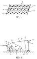
- FIG 1 illustrates the construction of the penta-layer battery separator of this invention.
- Figure 2 is a schematic illustration of a deplying and penta-layer formation setup.
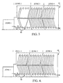
- Figure 3 shows the oven string-up for co-bonding and co-annealing the penta-layer precursor.
- Figure 4 illustrates the oven string-up for stretching the co-bonded and co-annealed penta-layer precursor.
- a battery is an electrochemical device that generates electric current by converting chemical energy to electrical energy. Its essential components are: positive and negative electrodes made of more or less electrically conductive materials; a separator; and an electrolyte. Batteries may be either primary (non-reversible or disposable) or secondary (reversible or rechargeable). The electrolyte may be aqueous or non-aqueous. Batteries are typically either spiral wound or prismatical (rectangular). These shapes are indicative of their method of manufacture. In the present invention, the preferred battery is lithium battery. The most preferred battery is a lithium ion secondary battery.
- FIG. 1 illustrates a preferred embodiment of shutdown battery separator 10 which comprises a microporous film for use in electrochemical cells, e.g., batteries, particularly rechargeable batteries, such as lithium batteries.
- This penta-layer separator has five microporous membranes stacked together.
- the first (12), third (16) and fifth (20) membranes, i.e., the two outer layers and the center layer, are strength layers.
- the second (14) and fourth (18) membranes are shutdown layers.
- the shutdown layers are capable of melting and filling the pores at a temperature (shutdown temperature) substantially below the melting point of the strength layers.
- shutdown temperature substantially below the melting point of the strength layers.
- the strength layers can be composed of, for example, a polyolefin such as polypropylene or a blend comprising substantially polypropylene or copolymer of polypropylene.
- An exemplary polypropylene is Fina PP 3271 resin commercially available from Fina Oil and Chemical Company, Dallas TX.
- the shutdown layers can be composed of polyethylene or a blend comprising substantially polyethylene or a copolymer comprising substantially polyethylene.
- An exemplary polyethylene is Fina HDPE 7208 resin commercially available from Fina Oil and Chemical Company, Dallas TX.
- the preferred embodiment of the invention has a polypropylene-polyethylene-polypropylene-polyethylene-polypropylene construction.
- the separator has a thickness of less than 2 mils (about 50 ⁇ m) preferably less than about 1.7 mil (about 42 ⁇ m) and more preferably has a thickness of less than about 1 mil (about 25 ⁇ m).
- the permeability of the separator as measured by Gurley, is less than about 50 seconds, and preferably less than about 40 seconds.
- the puncture strength of the separator is more than about 4.6N (470 grams-force (gf)), preferably more than 4.9N (500 gf).
- the penta-layer battery separator in accordance with the present invention has improved puncture strength and resistance to splitting.
- a 25.4 ⁇ m (1 mil) thick trilayer separator of polypropylene-polyethylene-polypropylene construction prepared by laminating PP and PE CELGARD® membranes has a puncture strength of about 4.4N (450 gf).
- a 25.4 ⁇ m (1 mil) penta-layer separator in accordance with the present invention has a puncture strength of about 5.1 N (520 gf), which is about 15% higher than a polypropylene-polyethylene-polypropylene separator with the same thickness of 25.4 ⁇ m (1-mil).
- the penta-layer separator of this invention can be made using any of the various methods generally known in the art for making microporous films or shutdown battery separators.
- the strength layers and the shutdown layers can be co-extruded or extruded separately. They can be bonded and annealed together before being converted to porous structure.
- Individual membranes can also be made porous and subsequently bonded and annealed into the penta-layer separator of this invention. The individual membranes may also be crossplied (i.e., see, U.S. Patent No. 5,667,911).
- a penta-layer separator is made in the following steps: extruding a non-porous strength layer precursor; extruding a non-porous shutdown layer precursor; forming a non-porous penta-layer precursor; bonding the penta-layer precursor; annealing the penta-layer precursor; and stretching the bonded and annealed, non-porous penta-layer precursor to form the microporous penta-layer shutdown separator.
- a 1.02 mm (40 mil) die gap in, e.g., a 68.6cm (27") width die is used for making the polypropylene and polyethylene precursors of the less than 25.4 ⁇ m (1-mil) penta-layer, whereas a 1.78 mm (70 mil) die gap is used for the precursors of thicker penta-layers;
- a die temperature for extruding the polypropylene precursor is in the range of 224°C (for 9.4 ⁇ m (0.37 mil) polypropylene precursor) to 234°C (for 6.1 ⁇ m (0.24 mil) polypropylene precursor);
- the die temperature for polyethylene precursors is in the range of 200°C (for 9.7 ⁇ m (0.38 mil) precursor) to 210°C (for 5.6 ⁇ m (0.22 mil) precursor);
- the barrel temperature is in the range of 200°C (for polyethylene) to 210°C (for polypropylene).
- the penta-layer precursor may be formed as shown in scheme 10 of Figure 2.
- the polypropylene precursors 24 are unwound from unwind stations 12 and 16.
- the polyethylene precursors 26 are unwound from unwind station 14.
- Two plies are supplied from each roll supported by an unwind station.
- Guide rollers 22 are used to assist in deplying the precursors. Only one ply supplied by the unwind station 16 is used in the formation of the penta-layer precursor. The other ply is rewound onto the roll supported by rewind station 18.
- the penta-layer precursor 20 is forwarded to the next processing operation (not shown).
- the non-porous films may be bonded and annealed before stretching.
- Co-bonding and co-annealing of the trilayer precursor may be performed in a multizone oven 40 of Figure 3, in which each zone is capable of maintaining a distinct temperature.
- Bonding is for joining together the single layers in the polypropylene-polyethylene-polypropylene-polyethylene- ⁇ polypropylene precursors. Bonding may be performed at a temperature ranging from 125-135°C between nip rollers 50. Preferably, bonding is performed at a temperature ranging from 128-130°C.
- the annealing step is used to form crystal structures in the polymers to facilitate pore formation in the later stretching step. Annealing is influenced by temperature and time. Annealing of the penta-layer precursor should be performed at temperatures ranging from 105-135°C, preferably from about 110-130°C.
- the penta-layer precursor is stretched a multizone oven 40 of Figure 4. Stretching the bonded and annealed penta-layer precursor causes the formation of micropores in the structure of the separator precursors. Stretching can include several steps, e.g., a cold drawing step, a hot drawing step, and a relax or heat-treating step. The relax or heat-treating step is to reduce internal stress within the separator and may be accomplished with either negative draw ratio or substantially no draw tension at various heat profiles. Stretching can be a continuous process performed in ovens containing draw frame.
- the cold drawing step can be conducted at ambient temperature and at a draw ratio in the range of 10-40%, preferably 15-25%.
- the hot drawing step can be conducted at temperatures ranging from 110-125°C, preferably 115-123°C, and at draw ratios ranging from 105-130%, preferably 110-125%.
- the relax or heat-treating step is conducted at temperatures ranging from 110-125°C and at a draw ratio in the range of -15% to -50%, preferably 115-123°C and at a draw ratio in the range of -20 to -40%.
- the penta-layer battery separators After stretching, the penta-layer battery separators are slit to desired widths and wound up into rolls.
- the penta-layer battery separator of this invention can be made by other methods generally known in the art for making two or three-layer shutdown battery separators with necessary modifications.
- the modifications needed should be apparent to a person skilled in the art in view of the method detailed above.
- suitable methods include, but not limited to: (1) co-stretching the bonded and annealed non-porous films that are separately extruded; (2) forming porous precursors before bonding them into penta-layer separators; and (3) stretching a co-extruded penta-layer precursor.
- cross-plied penta-layer microporous membranes comprising first, third and fifth microporous polypropylene membranes and second and forth microporous polyethylene membranes may also be made by cross-ply laminating the microporous membranes such that at least one layer is angularly oriented relative to at least another layer.
- Methods of making cross-ply microporous battery separator are disclosed in U.S. Patent No. 5,667,911.
- Gurley ASTM-D726(B) Gurley is a resistance to air flow measured time in seconds required to pass 10cc of air through 6.45 cm 2 (one square inch) of product under a pressure 31.0cm (12.2 inches) of water.
- Thickness T411om-83 developed under the auspices of the Technical Association of the Pulp and Paper Industry. Thickness is determined using a precision micrometer with a 1,27cm (1/2 inch) diameter, circular shoe contacting the sample at seven 48 kPa ((7) PSI). Ten (10) individual micrometer readings taken across the width of the sample are averaged.
- Porosity ASTM D-2873 Puncture Strength Ten measurements are made across the width of the stretched product and averaged.
- a Mitech Stevens LFRA Texture Analyzer is used.
- the needle is 1.65 mm in diameter with 0.5 mm radius.
- the rate of descent is 2 mm/sec and the amount of deflection is 6 mm.
- the film is held tight in the clamping device with a central hole of 11.3 mm.
- the displacement (in mm) of the film that was pierced by the needle was recorded against the resistance force 0.0098N (in gram force) developed by the tested film.
- the maximum resistance force is the puncture strength.
- the polyethylene precursor was extruded from Fina HDPE 7208 resin with a 1.02 mm (40-mil) die gap set-up to form a 0.22 mil (about 5.5 ⁇ m) thick film.
- the polypropylene precursor was extruded from Fina PP3271 resin with a 1.02 mm (40-mil) die gap set-up to form a 0.24 mil (about 6.0 ⁇ m) thick film.
- the penta-layer precursor was formed as shown in Figure 2.
- the bonding and annealing of the precursor was accomplished as follows: the precursor was strung-up with the oven configured as in Figure 3; the oven 40 has 4 zones.
- the nip rollers 50 are located in zone 2. Zones 2 was set at a temperature of 128°C or 130°C. Zone 3 and 4 were set at a temperature of 110°C.
- the line speed was 12.2 m/min. (40 ft/min).
- the pentalayer precursor was then stretched under various conditions to yield the penta-layer separator. The results are set forth in Table 1.
- the polyethylene precursor was extruded from Fina HDPE 7208 resin up to form a 0.38 mil (about 9.5 ⁇ m) thick film.
- the polypropylene precursor was extruded from Escorene PP 4292 resin to form a 0.37 mil (about 9.25 ⁇ m) thick film.
- the penta-layer precursor was formed as shown in Figure 2.
- the bonding and annealing of the precursor was accomplished as follows: the precursor was strung-up with the oven configured as in Figure 3.
- the oven 40 of Figure 3 has 4 zones.
- the nip rollers 50 are located in zone 2.
- Zones 2 was set at a temperature of 128°C or 130°C.
- Zone 3 and 4 were set at a temperature of 110°C.
- the line speed was 12.2 m/min (40 ft/min).
- the pentalayer precursor was then stretched under various conditions to yield the penta-layer separator. The results are set forth in Table 2.
Description
- The invention is directed to a penta-layer shutdown battery separator.
- A battery normally comprises electrodes, electrolyte, and a battery separator. Battery separators are located between the anode and cathode in a battery to prevent direct contact between electrodes of opposite polarity and to contain electrolyte.
- In lithium batteries which are increasingly popular, short circuiting is a problem as it tends to cause thermal runaway and battery rupture. Thus, shutdown separators have been developed to cope with this problem. For example, see: US Patent No. 4,650,730 and US Patent No. 4,731,304. A shutdown battery separator is a microporous membrane which closes its pores at some temperature well below the melting and/or ignition point of lithium to minimize the negative impact of thermal runaway.
- In addition to the shutdown function, a microporous shutdown separator should also be thin enough to minimize the space it occupies in the battery and to reduce electrical resistance. Moreover, the shutdown separator must also have sufficient resistance to splitting, and puncture strength. These two attributes are essential during handling or manufacture.
- Microporous membranes made of polypropylene generally have higher puncture strength; but, they melt at temperatures too near the melting point of lithium. On the other hand, polyethylene membranes generally have low melting temperatures but low puncture strength. Thus, trilayer shutdown batteries were developed comprising both microporous polypropylene and polyethylene membranes. See: Japanese Patent Application Nos. 98395/1994 and 98394/1994 both filed May 20, 1994 by Ube Industries, Ltd. (the Ube trilayer separator); U.S. Patent No. 5,691,077 by Hoechst Celanese Corporation (the CELGARD® separator); Japanese Patent Application No. 55550/1995 filed March 15, 1995 by Nitto Denko Kogyo K.K. (the Nitto Denko trilayer separator); and Japanese Patent Application No. 56320/1995 filed March 15, 1995 by Kureha Chemical Industry Co., Ltd. (the Kureha trilayer separator).
- All of foregoing claim trilayer battery separators comprising two layers of microporous polypropylene membrane sandwiching one layer of microporous polyethylene membrane. In addition, the Ube \ applications also disclose that porous laminate film can be obtained by stretching a laminate film of three or more alternate layers of polypropylene and polyethylene.
- One problem with trilayer battery separators is that they are prone to splitting, i.e., the tearing of the separator during handling or battery manufacture. Split separators are ineffective in preventing thermal runaway. Thus, if the separator splits, the battery is defective. In addition, it was observed that when samples of trilayer membranes are punctured by a needle, the membranes fail starting from the transverse direction, which indicates that the tendency to split also reduces the puncture strength of the membrane. Therefore, there is need to increase resistance to splitting in shutdown separators.
- This invention provides a battery separator of improved resistance to splitting and puncture strength having five microporous membranes laminated together. The first, third, and fifth membranes are strength layers, and preferably are polypropylene. The second and fourth layers are shutdown layers, and preferably are polyethylene. The present invention is based on the discovery that a penta-layer separator having a construction of polypropylene-polyethylene-polypropylene-polyethylene-polypropylene has much greater resistance to splitting than a trilayer separator having a polypropylene-polyethylene-polypropylene construction with the same thickness.
- For the purpose of explaining the invention, there is shown in the drawings various preferred aspects of the invention; it being understood, however, that this invention is not limited to the precise arrangements and instrumentalities shown.
- Figure 1 illustrates the construction of the penta-layer battery separator of this invention.
- Figure 2 is a schematic illustration of a deplying and penta-layer formation setup.
- Figure 3 shows the oven string-up for co-bonding and co-annealing the penta-layer precursor.
- Figure 4 illustrates the oven string-up for stretching the co-bonded and co-annealed penta-layer precursor.
- The present invention shall be described in further detail below by way of the following detailed description and the non-limiting examples.
- A battery is an electrochemical device that generates electric current by converting chemical energy to electrical energy. Its essential components are: positive and negative electrodes made of more or less electrically conductive materials; a separator; and an electrolyte. Batteries may be either primary (non-reversible or disposable) or secondary (reversible or rechargeable). The electrolyte may be aqueous or non-aqueous. Batteries are typically either spiral wound or prismatical (rectangular). These shapes are indicative of their method of manufacture. In the present invention, the preferred battery is lithium battery. The most preferred battery is a lithium ion secondary battery.
- Figure 1 illustrates a preferred embodiment of
shutdown battery separator 10 which comprises a microporous film for use in electrochemical cells, e.g., batteries, particularly rechargeable batteries, such as lithium batteries. This penta-layer separator has five microporous membranes stacked together. The first (12), third (16) and fifth (20) membranes, i.e., the two outer layers and the center layer, are strength layers. The second (14) and fourth (18) membranes are shutdown layers. The shutdown layers are capable of melting and filling the pores at a temperature (shutdown temperature) substantially below the melting point of the strength layers. Thus, when the micropores collapse at the shutdown temperature, the strength layers retain substantially their elastic energy and thus maintain the integrity of the separator in the event of short circuit and prevent the ion flow between the electrodes. - The strength layers can be composed of, for example, a polyolefin such as polypropylene or a blend comprising substantially polypropylene or copolymer of polypropylene. An exemplary polypropylene is Fina PP 3271 resin commercially available from Fina Oil and Chemical Company, Dallas TX. The shutdown layers can be composed of polyethylene or a blend comprising substantially polyethylene or a copolymer comprising substantially polyethylene. An exemplary polyethylene is Fina HDPE 7208 resin commercially available from Fina Oil and Chemical Company, Dallas TX. Thus, the preferred embodiment of the invention has a polypropylene-polyethylene-polypropylene-polyethylene-polypropylene construction. The separator has a thickness of less than 2 mils (about 50 µm) preferably less than about 1.7 mil (about 42 µm) and more preferably has a thickness of less than about 1 mil (about 25 µm). The permeability of the separator, as measured by Gurley, is less than about 50 seconds, and preferably less than about 40 seconds. The puncture strength of the separator is more than about 4.6N (470 grams-force (gf)), preferably more than 4.9N (500 gf).
- The penta-layer battery separator in accordance with the present invention has improved puncture strength and resistance to splitting. For example, a 25.4 µm (1 mil) thick trilayer separator of polypropylene-polyethylene-polypropylene construction prepared by laminating PP and PE CELGARD® membranes has a puncture strength of about 4.4N (450 gf). Surprisingly, a 25.4 µm (1 mil) penta-layer separator in accordance with the present invention has a puncture strength of about 5.1 N (520 gf), which is about 15% higher than a polypropylene-polyethylene-polypropylene separator with the same thickness of 25.4 µm (1-mil). As is known to a person skilled in the art, it is important to have thin separators, so that the electrical resistance across the separator, as well as, the size of the battery, may be reduced. Therefore, this invention, by increasing resistance to splitting without sacrificing the thinness, has great significance to battery separator manufacture.
- The penta-layer separator of this invention can be made using any of the various methods generally known in the art for making microporous films or shutdown battery separators. The strength layers and the shutdown layers can be co-extruded or extruded separately. They can be bonded and annealed together before being converted to porous structure. Individual membranes can also be made porous and subsequently bonded and annealed into the penta-layer separator of this invention. The individual membranes may also be crossplied (i.e., see, U.S. Patent No. 5,667,911).
- In the case of separate extrusion, preferably, a penta-layer separator is made in the following steps: extruding a non-porous strength layer precursor; extruding a non-porous shutdown layer precursor; forming a non-porous penta-layer precursor; bonding the penta-layer precursor; annealing the penta-layer precursor; and stretching the bonded and annealed, non-porous penta-layer precursor to form the microporous penta-layer shutdown separator.
- The methods for extruding non-porous precursor layers, which are thicker than the membranes in this invention, are disclosed in, by way of non-limiting example, U.S. Patent Nos.: 3,426,754; 3,558, 764; 3,679,538; 3,801,404; 3,801,692; 3,843,761; 3,853,601; 4,138,459; 4,539,256; 4,726,989; 4,994,335, and 5,691,077.
- In the preferred extrusion methods in the present invention: (1) a 1.02 mm (40 mil) die gap in, e.g., a 68.6cm (27") width die is used for making the polypropylene and polyethylene precursors of the less than 25.4 µm (1-mil) penta-layer, whereas a 1.78 mm (70 mil) die gap is used for the precursors of thicker penta-layers; (2) a die temperature for extruding the polypropylene precursor is in the range of 224°C (for 9.4 µm (0.37 mil) polypropylene precursor) to 234°C (for 6.1µm (0.24 mil) polypropylene precursor); (3) the die temperature for polyethylene precursors is in the range of 200°C (for 9.7µm (0.38 mil) precursor) to 210°C (for 5.6 µm (0.22 mil) precursor); (4) the barrel temperature is in the range of 200°C (for polyethylene) to 210°C (for polypropylene).
- The penta-layer precursor may be formed as shown in
scheme 10 of Figure 2. Thepolypropylene precursors 24 are unwound from unwindstations polyethylene precursors 26 are unwound from unwindstation 14. Two plies are supplied from each roll supported by an unwind station.Guide rollers 22 are used to assist in deplying the precursors. Only one ply supplied by the unwindstation 16 is used in the formation of the penta-layer precursor. The other ply is rewound onto the roll supported byrewind station 18. The penta-layer precursor 20 is forwarded to the next processing operation (not shown). - After the extrusion, the non-porous films may be bonded and annealed before stretching. Co-bonding and co-annealing of the trilayer precursor may be performed in a
multizone oven 40 of Figure 3, in which each zone is capable of maintaining a distinct temperature. Bonding is for joining together the single layers in the polypropylene-polyethylene-polypropylene-polyethylene- \ polypropylene precursors. Bonding may be performed at a temperature ranging from 125-135°C between niprollers 50. Preferably, bonding is performed at a temperature ranging from 128-130°C. The annealing step is used to form crystal structures in the polymers to facilitate pore formation in the later stretching step. Annealing is influenced by temperature and time. Annealing of the penta-layer precursor should be performed at temperatures ranging from 105-135°C, preferably from about 110-130°C. - Following the bonding and annealing steps, the penta-layer precursor is stretched a
multizone oven 40 of Figure 4. Stretching the bonded and annealed penta-layer precursor causes the formation of micropores in the structure of the separator precursors. Stretching can include several steps, e.g., a cold drawing step, a hot drawing step, and a relax or heat-treating step. The relax or heat-treating step is to reduce internal stress within the separator and may be accomplished with either negative draw ratio or substantially no draw tension at various heat profiles. Stretching can be a continuous process performed in ovens containing draw frame. - The cold drawing step can be conducted at ambient temperature and at a draw ratio in the range of 10-40%, preferably 15-25%. The hot drawing step can be conducted at temperatures ranging from 110-125°C, preferably 115-123°C, and at draw ratios ranging from 105-130%, preferably 110-125%. The relax or heat-treating step is conducted at temperatures ranging from 110-125°C and at a draw ratio in the range of -15% to -50%, preferably 115-123°C and at a draw ratio in the range of -20 to -40%.
- After stretching, the penta-layer battery separators are slit to desired widths and wound up into rolls.
- Alternatively, the penta-layer battery separator of this invention can be made by other methods generally known in the art for making two or three-layer shutdown battery separators with necessary modifications. The modifications needed should be apparent to a person skilled in the art in view of the method detailed above. Examples of suitable methods include, but not limited to: (1) co-stretching the bonded and annealed non-porous films that are separately extruded; (2) forming porous precursors before bonding them into penta-layer separators; and (3) stretching a co-extruded penta-layer precursor. These methods are disclosed in the following patents and patent applications:
- U.S. Pat. Nos.: 4,650,730; 4,471,304; 5,240,655; 5,281,491; 5,667,911; 5,565,281; Japanese Applications JP 98394/1994; 98395/1994; 7-56320; and UK Application GB 2298817.
- In addition, cross-plied penta-layer microporous membranes comprising first, third and fifth microporous polypropylene membranes and second and forth microporous polyethylene membranes may also be made by cross-ply laminating the microporous membranes such that at least one layer is angularly oriented relative to at least another layer. Methods of making cross-ply microporous battery separator are disclosed in U.S. Patent No. 5,667,911.
- The invention is further illustrated with reference to the examples set forth below. In the examples, the following methods are employed to for testing:
Test Methods Gurley ASTM-D726(B) Gurley is a resistance to air flow measured time in seconds required to pass 10cc of air through 6.45 cm2 (one square inch) of product under a pressure 31.0cm (12.2 inches) of water. Thickness T411om-83 developed under the auspices of the Technical Association of the Pulp and Paper Industry. Thickness is determined using a precision micrometer with a 1,27cm (1/2 inch) diameter, circular shoe contacting the sample at seven 48 kPa ((7) PSI). Ten (10) individual micrometer readings taken across the width of the sample are averaged. Porosity ASTM D-2873 Puncture Strength Ten measurements are made across the width of the stretched product and averaged. A Mitech Stevens LFRA Texture Analyzer is used. The needle is 1.65 mm in diameter with 0.5 mm radius. The rate of descent is 2 mm/sec and the amount of deflection is 6 mm. The film is held tight in the clamping device with a central hole of 11.3 mm. The displacement (in mm) of the film that was pierced by the needle was recorded against the resistance force 0.0098N (in gram force) developed by the tested film. The maximum resistance force is the puncture strength. Peel Strength Peel strength is measured using a tension and compression tester to determine the force in 0.0098N (grams) required to separate two 2.54 cm (one-inch) wide sections of bonded membrane. The peel rate is 15.24 cm/min (6 inches/minute). Three measurements are taken across the web and averaged. Shrinkage The sample in the machine direction is marked Li (Li = 9.99cm) apart, and then suspended in a convection oven set at 90°C for one hour. After taking out of the oven, the sample is then measured the distance, Lf, between the marks. The shrinkage is calculated as follows: (%) Shrinkage = (Li - Lf) X 100/Lf. - The polyethylene precursor was extruded from Fina HDPE 7208 resin with a 1.02 mm (40-mil) die gap set-up to form a 0.22 mil (about 5.5 µm) thick film. The polypropylene precursor was extruded from Fina PP3271 resin with a 1.02 mm (40-mil) die gap set-up to form a 0.24 mil (about 6.0 µm) thick film. The penta-layer precursor was formed as shown in Figure 2.
- The bonding and annealing of the precursor was accomplished as follows: the precursor was strung-up with the oven configured as in Figure 3; the
oven 40 has 4 zones. The niprollers 50 are located inzone 2.Zones 2 was set at a temperature of 128°C or 130°C. Zone Trial # Gurley ± range, sec Thickness ±σ, 25.4µm (mil) Shrinkage % Puncture Strength, ±σ, 0.0098 N (gf) Base Weight, mg/cm2 Roll Length,(30.48cm) (ft) 1 43.4+4.3 1.05+0.04 1.3 1.61 700 2 39.4+6.5 1.02+0.03 1.3 516+44 1.59 700 3 40.3+1.8 1.05+0.02 1.3 1.57 700 4 41.2+7.7 1.00+0.04 1.3 1.57 700 5 34.1+5.4 1.03+0.03 1.2 1.55 700 6 33.0+4.2 1.01+0.04 1.3 1.52 700 7 36.3+7.0 1.05+0.03 1.4 1.54 700 8 35.2+8.4 1.01+0.02 1.2 1.53 700 9 35.1+4.0 1.04+0.03 1.5 527+32 1.58 1600 10 34.3+3.4 1.05+0.08 1.4 1.60 1600 11 34.0+6.0 1.02+0.02 1.5 1.58 1600 12 36.0+5.0 1.04+0.03 1.4 1.61 1600 Where σ is standard deviation - The polyethylene precursor was extruded from Fina HDPE 7208 resin up to form a 0.38 mil (about 9.5 µm) thick film. The polypropylene precursor was extruded from Escorene PP 4292 resin to form a 0.37 mil (about 9.25 µm) thick film. The penta-layer precursor was formed as shown in Figure 2.
- The bonding and annealing of the precursor was accomplished as follows: the precursor was strung-up with the oven configured as in Figure 3. The
oven 40 of Figure 3 has 4 zones. The niprollers 50 are located inzone 2.Zones 2 was set at a temperature of 128°C or 130°C. Zone Trial # Gurley ± range, sec Thickness ±σ, (mil) 25,4µm Shrinkage % Puncture Strength, ±σ (0,0098 N) (gf) Base Weight, mg/cm2 Roil Length, (30,48cm) (ft) 1 39.6+9.5 1.65+0.02 1.3 2.35 700 2 44.6+5.9 1.65+0.02 1.3 742+18 2.33 700 3 38.1+6.2 1.66+0.02 1.3 2.37 700 4 43.4+6.2 1.65+0.06 1.3 2.32 700 5 34.4+4.2 1.60+0.04 0.8 2.18 700 6 35.5+6.0 1.59+0.04 0.8 2.20 700 7 33.2+2.5 1.59+0.03 0.8 2.18 700 8 35.4+9.04 1.61+0.03 0.8 2.24 700 Where σ is standard deviation
Claims (8)
- A battery separator comprising:
five microporous membranes stacked together, wherein the first, third, and fifth membranes are strength layers, and second and fourth membranes are shutdown layers. - A battery separator according to claim 1, wherein the first, third and fifth membranes are polypropylene and the second and fourth membranes are polyethylene.
- A battery separator according to claim 1 or 2 wherein the separator has a thickness of no greater than 25.4 µm (1 mil).
- A cross-ply microporous penta-layer battery separator comprising:
five microporous membranes stacked together, the first, third and fifth membranes being polypropylene and the second and fourth membranes being polyethylene, wherein the uniaxial orientation of at least one ply is at an angle relative to the uniaxial orientation of at least one other ply. - A battery comprising an anode, a cathode, an electrolyte and a separator, the electrolyte being contained in the separator, the anode and the cathode sandwiching the separator, so that the electrolyte is in ion communication therebetween, and the separator of claims 1 or 2 or 4.
- A method for making a penta-layer separator comprising the step of:extruding a polyethylene precursor;extruding a polypropylene precursor;forming a penta-layer precursor wherein the first, third and fifth membranes are polypropylene precursors, and the second and forth membranes are polyethylene precursors;simultaneously bonding and annealing the penta-layer precursor to form a bonded and annealed penta-layer precursor;stretching the bonded and annealed penta-layer precursor; andforming thereby the battery separator.
- A method for making a penta-layer battery separator comprising:forming microporous polypropylene membranes and microporous polyethylene membranes;laminating said membranes into a penta-layer precursor wherein the first, third and fifth membranes are polypropylene, and the second and forth membranes are polyethylene; andbonding said penta-layer precursor to form the penta-layer battery separator.
- A method of making a penta-layer battery separator comprising:co-extruding a penta-layer precursor wherein the first, third and fifth membranes are polypropylene precursors, and the second and forth membranes are polyethylene precursors;annealing said penta-layer precursor; and forming microporous structure in the annealed penta-layer precursor.
Applications Claiming Priority (2)
| Application Number | Priority Date | Filing Date | Title |
|---|---|---|---|
| US99520597A | 1997-12-19 | 1997-12-19 | |
| US995205 | 1997-12-19 |
Publications (2)
| Publication Number | Publication Date |
|---|---|
| EP0924780A1 EP0924780A1 (en) | 1999-06-23 |
| EP0924780B1 true EP0924780B1 (en) | 2001-07-11 |
Family
ID=25541519
Family Applications (1)
| Application Number | Title | Priority Date | Filing Date |
|---|---|---|---|
| EP98123315A Expired - Lifetime EP0924780B1 (en) | 1997-12-19 | 1998-12-08 | Penta-layer battery separator |
Country Status (6)
| Country | Link |
|---|---|
| EP (1) | EP0924780B1 (en) |
| JP (1) | JPH11250888A (en) |
| KR (1) | KR19990063109A (en) |
| CA (1) | CA2253017A1 (en) |
| DE (1) | DE69801093T2 (en) |
| TW (1) | TW420886B (en) |
Cited By (1)
| Publication number | Priority date | Publication date | Assignee | Title |
|---|---|---|---|---|
| US9227346B2 (en) | 2004-10-22 | 2016-01-05 | Dow Global Technologies Llc | Plastic composite articles and methods of making same |
Families Citing this family (11)
| Publication number | Priority date | Publication date | Assignee | Title |
|---|---|---|---|---|
| US6602593B1 (en) * | 1999-08-30 | 2003-08-05 | Celgard Inc. | Battery separators with reduced splitting propensity |
| US6749961B1 (en) * | 2000-04-10 | 2004-06-15 | Celgard Inc. | Shutdown battery separator made with a blend of polymer and oligomer |
| TW595035B (en) * | 2000-08-30 | 2004-06-21 | Sumitomo Chemical Co | Separator for non-aqueous electrolyte secondary battery, and non-aqueous electrolyte secondary battery |
| US8945753B2 (en) * | 2005-01-26 | 2015-02-03 | Medtronic, Inc. | Implantable battery having thermal shutdown separator |
| US10003058B2 (en) | 2006-11-17 | 2018-06-19 | Celgard, Llc | Method of making a co-extruded, multi-layered battery separator |
| WO2010048395A2 (en) * | 2008-10-24 | 2010-04-29 | Tonen Chemical Corporation | Multilayer microporous membranes, methods of making such membranes and the use of such membranes on battery separator film |
| US8697272B2 (en) * | 2009-09-01 | 2014-04-15 | Samsung Sdi Co., Ltd. | Secondary battery having an insulating member |
| US11495865B2 (en) * | 2016-11-11 | 2022-11-08 | Celgard, Llc | Microlayer membranes, improved battery separators, and related methods |
| WO2020060886A1 (en) * | 2018-09-17 | 2020-03-26 | Celgard, Llc | Multilayer membranes, separators, batteries, and methods |
| CN109980164A (en) * | 2019-03-18 | 2019-07-05 | 宁德新能源科技有限公司 | Isolation film and electrochemical appliance |
| CN115411458A (en) * | 2022-09-09 | 2022-11-29 | 深圳市博盛新材料有限公司 | Five-layer co-extrusion diaphragm and preparation method thereof |
Family Cites Families (6)
| Publication number | Priority date | Publication date | Assignee | Title |
|---|---|---|---|---|
| US4863792A (en) * | 1988-10-14 | 1989-09-05 | Minnesota Mining And Manufacturing Company | Multi-layer laminates of microporous films |
| WO1993013565A1 (en) * | 1991-12-20 | 1993-07-08 | W.R. Grace & Co.-Conn. | Multi-ply battery separator and process of forming |
| US5691047A (en) * | 1994-05-12 | 1997-11-25 | Ube Industries, Ltd. | Porous multi-layer film |
| JP3011309B2 (en) * | 1994-05-12 | 2000-02-21 | 宇部興産株式会社 | Battery separator and method of manufacturing the same |
| TW297171B (en) * | 1994-12-20 | 1997-02-01 | Hoechst Celanese Corp | |
| JPH08250097A (en) * | 1995-03-15 | 1996-09-27 | Kureha Chem Ind Co Ltd | Interpole separator for electrochemical device |
-
1998
- 1998-11-03 TW TW087118270A patent/TW420886B/en not_active IP Right Cessation
- 1998-11-05 CA CA002253017A patent/CA2253017A1/en not_active Abandoned
- 1998-12-08 EP EP98123315A patent/EP0924780B1/en not_active Expired - Lifetime
- 1998-12-08 DE DE69801093T patent/DE69801093T2/en not_active Expired - Fee Related
- 1998-12-16 KR KR1019980055397A patent/KR19990063109A/en not_active Application Discontinuation
- 1998-12-18 JP JP10359899A patent/JPH11250888A/en active Pending
Cited By (1)
| Publication number | Priority date | Publication date | Assignee | Title |
|---|---|---|---|---|
| US9227346B2 (en) | 2004-10-22 | 2016-01-05 | Dow Global Technologies Llc | Plastic composite articles and methods of making same |
Also Published As
| Publication number | Publication date |
|---|---|
| JPH11250888A (en) | 1999-09-17 |
| DE69801093T2 (en) | 2002-04-18 |
| KR19990063109A (en) | 1999-07-26 |
| TW420886B (en) | 2001-02-01 |
| EP0924780A1 (en) | 1999-06-23 |
| DE69801093D1 (en) | 2001-08-16 |
| CA2253017A1 (en) | 1999-06-19 |
Similar Documents
| Publication | Publication Date | Title |
|---|---|---|
| EP0872900B1 (en) | Method of making a trilayer battery separator | |
| EP0892448B1 (en) | Shutdown, trilayer battery separator and process of manufacture | |
| US11731407B2 (en) | Low electrical resistance microporous battery separator membranes, separators, cells, batteries, and related methods | |
| US11101525B2 (en) | Laminated multilayer membranes, separators, batteries, and methods | |
| EP0715364B1 (en) | Shutdown, bilayer battery separator | |
| US6602593B1 (en) | Battery separators with reduced splitting propensity | |
| US9112214B2 (en) | Battery separator and method of making same | |
| JP6257228B2 (en) | Method for producing microporous multilayer film for battery separator | |
| EP0723304A2 (en) | Methods of making cross-ply microporous membrane battery separator, and the battery separators made thereby | |
| US20070207376A1 (en) | Multilayer battery separators | |
| JP2007311332A (en) | Multi-layer separation film with improved strength and stability | |
| EP0924780B1 (en) | Penta-layer battery separator | |
| JP3436055B2 (en) | Battery separator | |
| JPH11115084A (en) | Laminated porous film | |
| JP3508510B2 (en) | Laminated porous film and method for producing the same |
Legal Events
| Date | Code | Title | Description |
|---|---|---|---|
| PUAI | Public reference made under article 153(3) epc to a published international application that has entered the european phase |
Free format text: ORIGINAL CODE: 0009012 |
|
| AK | Designated contracting states |
Kind code of ref document: A1 Designated state(s): DE FR GB IT |
|
| AX | Request for extension of the european patent |
Free format text: AL;LT;LV;MK;RO;SI |
|
| 17P | Request for examination filed |
Effective date: 19991119 |
|
| AKX | Designation fees paid |
Free format text: DE FR GB IT |
|
| RAP1 | Party data changed (applicant data changed or rights of an application transferred) |
Owner name: CELGARD INC. |
|
| 17Q | First examination report despatched |
Effective date: 20000414 |
|
| GRAG | Despatch of communication of intention to grant |
Free format text: ORIGINAL CODE: EPIDOS AGRA |
|
| GRAG | Despatch of communication of intention to grant |
Free format text: ORIGINAL CODE: EPIDOS AGRA |
|
| GRAH | Despatch of communication of intention to grant a patent |
Free format text: ORIGINAL CODE: EPIDOS IGRA |
|
| GRAH | Despatch of communication of intention to grant a patent |
Free format text: ORIGINAL CODE: EPIDOS IGRA |
|
| GRAA | (expected) grant |
Free format text: ORIGINAL CODE: 0009210 |
|
| AK | Designated contracting states |
Kind code of ref document: B1 Designated state(s): DE FR GB IT |
|
| REF | Corresponds to: |
Ref document number: 69801093 Country of ref document: DE Date of ref document: 20010816 |
|
| ITF | It: translation for a ep patent filed |
Owner name: MODIANO & ASSOCIATI S.R.L. |
|
| ET | Fr: translation filed | ||
| REG | Reference to a national code |
Ref country code: GB Ref legal event code: IF02 |
|
| PLBE | No opposition filed within time limit |
Free format text: ORIGINAL CODE: 0009261 |
|
| STAA | Information on the status of an ep patent application or granted ep patent |
Free format text: STATUS: NO OPPOSITION FILED WITHIN TIME LIMIT |
|
| 26N | No opposition filed |
Opponent name: KONINKLIJKE PHILIPS ELECTRONICS N.V. |
|
| PGFP | Annual fee paid to national office [announced via postgrant information from national office to epo] |
Ref country code: GB Payment date: 20051104 Year of fee payment: 8 |
|
| PGFP | Annual fee paid to national office [announced via postgrant information from national office to epo] |
Ref country code: FR Payment date: 20051201 Year of fee payment: 8 |
|
| PGFP | Annual fee paid to national office [announced via postgrant information from national office to epo] |
Ref country code: DE Payment date: 20051230 Year of fee payment: 8 |
|
| PGFP | Annual fee paid to national office [announced via postgrant information from national office to epo] |
Ref country code: IT Payment date: 20061231 Year of fee payment: 9 |
|
| PG25 | Lapsed in a contracting state [announced via postgrant information from national office to epo] |
Ref country code: DE Free format text: LAPSE BECAUSE OF NON-PAYMENT OF DUE FEES Effective date: 20070703 |
|
| GBPC | Gb: european patent ceased through non-payment of renewal fee |
Effective date: 20061208 |
|
| REG | Reference to a national code |
Ref country code: FR Ref legal event code: ST Effective date: 20070831 |
|
| PG25 | Lapsed in a contracting state [announced via postgrant information from national office to epo] |
Ref country code: GB Free format text: LAPSE BECAUSE OF NON-PAYMENT OF DUE FEES Effective date: 20061208 |
|
| PG25 | Lapsed in a contracting state [announced via postgrant information from national office to epo] |
Ref country code: FR Free format text: LAPSE BECAUSE OF NON-PAYMENT OF DUE FEES Effective date: 20070102 |
|
| PG25 | Lapsed in a contracting state [announced via postgrant information from national office to epo] |
Ref country code: IT Free format text: LAPSE BECAUSE OF NON-PAYMENT OF DUE FEES Effective date: 20071208 |