EP1046974A2 - Actuating device for a radiator valve - Google Patents
Actuating device for a radiator valve Download PDFInfo
- Publication number
- EP1046974A2 EP1046974A2 EP00201025A EP00201025A EP1046974A2 EP 1046974 A2 EP1046974 A2 EP 1046974A2 EP 00201025 A EP00201025 A EP 00201025A EP 00201025 A EP00201025 A EP 00201025A EP 1046974 A2 EP1046974 A2 EP 1046974A2
- Authority
- EP
- European Patent Office
- Prior art keywords
- ring
- housing
- union nut
- attachment according
- attachment
- Prior art date
- Legal status (The legal status is an assumption and is not a legal conclusion. Google has not performed a legal analysis and makes no representation as to the accuracy of the status listed.)
- Granted
Links
Images

Classifications
-
- G—PHYSICS
- G05—CONTROLLING; REGULATING
- G05D—SYSTEMS FOR CONTROLLING OR REGULATING NON-ELECTRIC VARIABLES
- G05D23/00—Control of temperature
- G05D23/01—Control of temperature without auxiliary power
- G05D23/02—Control of temperature without auxiliary power with sensing element expanding and contracting in response to changes of temperature
- G05D23/021—Control of temperature without auxiliary power with sensing element expanding and contracting in response to changes of temperature the sensing element being a non-metallic solid, e.g. elastomer, paste
- G05D23/023—Control of temperature without auxiliary power with sensing element expanding and contracting in response to changes of temperature the sensing element being a non-metallic solid, e.g. elastomer, paste the sensing element being placed outside a regulating fluid flow
Definitions
- the invention relates to a radiator valve control unit with a housing, an attachment piece with a internal mesh geometry and an external thread, a union nut that can be turned on the external thread and a ring to cover a gap between Housing and union nut.
- Such an attachment is known from DE 44 42 402 C1.
- the ring is designed as a sleeve which is axially from an assembly position in which the union nut is accessible is in a position of use in which the attachment piece is covered with the union nut, is adjustable.
- you can change the visual appearance of the assembled radiator valve control unit improve because of the gap between the actual Valve and the housing of the control unit covered becomes.
- the handling is such Control unit not unproblematic during assembly.
- the sleeve must also be a bit in the assembled position protrude from the case so that they can be gripped can. In this area, however, it can be a finger Hinder assemblers or a tool to tighten the mother is used.
- the invention has for its object a space between the union nut and the housing cover without hindering assembly.
- This task is done with a radiator valve control unit of the type mentioned in that the ring is rotatably arranged on the housing and with the Union nut is in rotary engagement.
- the ring can not only be used to cover the gap used between the union nut and the housing but also as an assembly aid. If you do that Ring turns, then the union nut is also twisted. It can be adjusted axially on the external thread and thus the control unit at the desired Set the radiator valve.
- the ring on the housing is preferably in the axial direction fixed. If in the following by axial, radial or Circumferential direction, these directions refer on the axis of the external thread. If the Ring is fixed on the housing in the axial direction, then there can be no axial displacements that the Change the desired visual impression of the control unit could. It is always ensured that none annoying gap between the housing and the union nut arises, not even with an accidental mishandling or failure to do so of resetting the ring. This increases the assembly security.
- the union nut is preferably on the external thread can be positioned so close to the housing that outer end areas of the attachment socket can be deformed radially outwards are.
- the attachment nozzle in axially extending slots on a peripheral wall, so that the attachment piece by resilient radially outwards Legs is formed. These legs can then overlap Move the protrusions on the radiator valve away. If the Then union nut towards the axial outer Screwed at the end of the attachment socket, these are Legs on the corresponding part of the radiator valve created and held. If you take care of it now carries that the union nut on the nozzle screwed relatively far towards the housing assembly can be made easier. The The mother is so close to the housing that the legs can easily spring outwards.
- the ring is advantageously in a circumferential groove Housing led. This makes it easier to twist on the one hand and the definition in the axial direction on the other ensure.
- the ring and the housing are preferably together locked. This makes production easier. One can slide the ring onto the housing and by axial Pressure with opposite projections engage one after the other, assemble. Of course it is also possible the ring from several parts, for example to put together two parts, in this Fall the latch between the housing and the ring can be done that the two ring parts with each other be locked.
- the ring is advantageously opposite the union nut freely rotatable by a limited angle.
- the Ring must be capable of a certain torque transfer to the union nut to the union nut to be able to twist on the external thread. This However, turning intervention does not have to extend over the entire scope can be done. If the ring can be turned freely then you can take advantage of this opportunity to for example, a more pleasing visual design achieve or take action that is better Ensure ventilation of the control unit.
- the latter is particularly advantageous if the tax attachment is designed as a thermostat attachment.
- the limited relative rotatability is preferred realized in that the union nut at least one radially outward and the ring at least one has a radially inwardly projecting projection that each other cover at least partially in the circumferential direction, the gap between protrusions on one Part is larger than the width of the protrusions on the other Part.
- the ring becomes like this for torque transmission turned long until his lead or his Projections on the corresponding projections of the union nut issue. Another twist of the ring causes its projections to match the mother's projections push in front of you and thus the desired torque transferred to the union nut. Will the Direction of rotation of the ring changed, then the Protrusions from each other.
- the ring can now be relative twisted in the other direction to the union nut until its ledges on the other end of the Gap between the projections on the union nut with the torque application surfaces not previously applied of the corresponding head start. Then the twist of the union nut in the opposite direction.
- At least two pairs of projections are preferably rotationally symmetrical arranged to the axis of rotation. So that will also the torque transmission when screwing in and out the union nut kept symmetrical, and the The risk of accidental damage remains small.
- the ring can at least have two opposing openings. In this case there is also an air flow through the Enables space that in and of itself is covered by the ring is.
- the ring advantageously has at its radial An arrangement of torque application surfaces on the outside on. This makes it easier to apply torque and the nut already by hand with a certain Screw on strength. If necessary you can also attach a tool to the ring that the torque application area is sufficient Torque transmission enabled.
- the arrangement is a Has a plurality of webs projecting radially outwards, whose width in the circumferential direction is the width of corresponding webs on the outside of the union nut corresponds.
- This configuration has two advantages. On the one hand, this creates a pleasing appearance.
- the "pattern" on the outside of the ring is correct essentially with the "pattern” on the outside of the Cap nut. On the other hand you can then for twisting the two parts ring and union nut use the same tool.
- a radiator valve control attachment is in the present Embodiment designed as a thermostat attachment 1 with a housing 2, in which a thermostat element 3 is arranged is.
- the axial position of the thermostat element 3 can be changed using a rotary handle 4 be connected to the housing via a thread 5 is.
- the thermostat element 3 acts via an actuator 6 on a tappet surface 7 on which in the assembled State (Fig. 4) a plunger 8 of a radiator valve 9 is present. The further the plunger 8 is pressed becomes, the more the radiator valve 9 throttles.
- valve can also be used for control a heating surface used in underfloor heating become.
- the thermostat attachment 1 To attach the thermostat attachment 1 to the valve 9 is an attachment piece 10 with an engagement geometry 11 provided.
- the engagement geometry 11 has, for example an inwardly projecting projection 12, the behind a corresponding counter projection 13 on Radiator valve 9 can be brought to the plant.
- the Attachment neck 11 has distributed in the circumferential direction four axially extending slots 14 between legs 15 form which are radial due to the slots 14 can spring slightly outwards around the projections 12, 13 to be able to pass each other.
- the external thread 16 extends to the housing 2 so that the union nut 17 on the entire length of the nozzle 10 in any desired Position can be set. So you can for example screwed up to the housing 2, so that when you put the thermostat attachment 1 on the valve 9 does not hinder the extension of the legs 15.
- the Union nut 17 two projections projecting radially outwards 26 on, while the ring 19 two radially after has projections 27 projecting inside.
- the Gaps between the two projections 27 in the circumferential direction larger than the width of the projections 26 in the circumferential direction and vice versa.
- the ring 19 can be turned clockwise take the union nut 17 with you, i.e. a torque transferred to the union nut. Will the ring 19 rotated counterclockwise, then is one free rotation over an angular range of 180 ° minus the width of the two projections 26, 27 possible, before the respective projection 27 on the projection 26 comes to the plant, which he has not yet applied Has.
- This can be a friction-increasing Layer on the inside of the ring or the outside of the nut, for example made of rubber, be provided.
- ring 19 on his Circumferential surface a number of radially protruding and in has essential axially extending webs 31, the serve as torque application surfaces. These webs 31 have essentially the same in the circumferential direction Width like corresponding webs 32, which act as torque application surfaces used on the union nut 17 become. You can then, if necessary, by twisting of the ring 19, the webs 31, 32 in alignment with each other bring to the visual appearance too improve. You can also use a single tool turn both the ring 19 and the union nut 17, if this after rotation of the ring 19th protrudes far enough from the ring 19.
- FIG. 5 shows a slightly modified embodiment. All that has been added is that the ring 19 ' Has openings 33 through which the air flow 29 'pass can to cool the valve 9 or dissipate heat. Of course, it is also possible that air through the annular gap 28 occurs. This air path was out Not shown for reasons of clarity.
- the openings 33 can now by the free rotatability of the Ring 19 'opposite the housing 2 and the union nut 17 are aligned so that they are vertically one above the other. The flow is in this orientation the cheapest.
Abstract
Description
Die Erfindung betrifft einen Heizkörperventil-Steueraufsatz mit einem Gehäuse, einem Aufsatzstutzen mit einer inneren Eingriffsgeometrie und einem Außengewinde, einer Überwurfmutter, die auf dem Außengewinde verdrehbar ist, und einem Ring zum Abdecken einer Lücke zwischen Gehäuse und Überwurfmutter.The invention relates to a radiator valve control unit with a housing, an attachment piece with a internal mesh geometry and an external thread, a union nut that can be turned on the external thread and a ring to cover a gap between Housing and union nut.
Ein derartiger Aufsatz ist aus DE 44 42 402 C1 bekannt. Dort ist der Ring als Hülse ausgebildet, der axial von einer Montagelage, in der die Überwurfmutter zugänglich ist, in eine Gebrauchslage, in der der Aufsatzstutzen mit der Überwurfmutter abgedeckt ist, verstellbar ist. Mit Hilfe der Hülse kann man das optische Erscheinungsbild des montierten Heizkörperventil-Steueraufsatzes verbessern, weil die Lücke zwischen dem eigentlichen Ventil und dem Gehäuse des Steueraufsatzes abgedeckt wird. Allerdings ist die Handhabung eines derartigen Steueraufsatzes bei der Montage nicht unproblematisch. Die Hülse muß auch in der Montagelage ein Stück weit aus dem Gehäuse vorstehen, damit sie ergriffen werden kann. In diesem Bereich kann sie aber die Finger eines Monteurs oder ein Werkzeug behindern, das zum Festziehen der Mutter verwendet wird.Such an attachment is known from DE 44 42 402 C1. There the ring is designed as a sleeve which is axially from an assembly position in which the union nut is accessible is in a position of use in which the attachment piece is covered with the union nut, is adjustable. With the help of the sleeve you can change the visual appearance of the assembled radiator valve control unit improve because of the gap between the actual Valve and the housing of the control unit covered becomes. However, the handling is such Control unit not unproblematic during assembly. The sleeve must also be a bit in the assembled position protrude from the case so that they can be gripped can. In this area, however, it can be a finger Hinder assemblers or a tool to tighten the mother is used.
Der Erfindung liegt die Aufgabe zugrunde, einen Zwischenraum zwischen der Überwurfmutter und dem Gehäuse abzudecken, ohne die Montage zu behindern.The invention has for its object a space between the union nut and the housing cover without hindering assembly.
Diese Aufgabe wird bei einem Heizkörperventil-Steueraufsatz der eingangs genannten Art dadurch gelöst, daß der Ring am Gehäuse drehbar angeordnet ist und mit der Überwurfmutter in Dreheingriff steht.This task is done with a radiator valve control unit of the type mentioned in that the ring is rotatably arranged on the housing and with the Union nut is in rotary engagement.
Damit kann der Ring nicht nur zum Abdecken der Lücke zwischen der Überwurfmutter und dem Gehäuse verwendet werden, sondern auch als Montagehilfe. Wenn man den Ring dreht, dann wird auch die Überwurfmutter verdreht. Sie kann damit auf dem Außengewinde axial verstellt werden und somit den Steueraufsatz an dem gewünschten Heizkörperventil festlegen. Der Gebrach eines zusätzlichen Werkzeuges zum Festziehen der Überwurfmutter ist, wenn überhaupt, lediglich am Ende des Befestigungsvorgangs erforderlich. In diesem Fall ist die Überwurfmutter aber axial weit genug unter dem Ring hervorgetreten, so daß ein Werkzeug angesetzt werden kann. In den übrigen Abschnitten des Befestigungsvorganges reicht das mit Hilfe des Ringes auf die Überwurfmutter übertragene Drehmoment aus, um die Verschraubung zu bewirken.So the ring can not only be used to cover the gap used between the union nut and the housing but also as an assembly aid. If you do that Ring turns, then the union nut is also twisted. It can be adjusted axially on the external thread and thus the control unit at the desired Set the radiator valve. The use of an additional Tool for tightening the union nut, if at all, only at the end of the fastening process required. In this case, the union nut but emerged axially far enough under the ring so that a tool can be attached. In the remaining sections of the fastening process is sufficient the one transferred to the union nut using the ring Torque to effect the screw connection.
Vorzugsweise ist der Ring am Gehäuse in Axialrichtung festgelegt. Wenn im folgenden von Axial-, Radial- oder Umfangsrichtung die Rede ist, beziehen sich diese Richtungsangaben auf die Achse des Außengewindes. Wenn der Ring am Gehäuse in Axialrichtung festgelegt ist, dann können keine axialen Verschiebungen erfolgen, die den gewünschten optischen Eindruck des Steueraufsatzes verändern könnten. Es ist immer sichergestellt, daß kein störender Spalt zwischen dem Gehäuse und der Überwurfmutter entsteht, und zwar auch nicht bei einer versehentlichen falschen Handhabung oder bei einem Unterlassen des Rückstellens des Ringes. Dies erhöht die Montagesicherheit.The ring on the housing is preferably in the axial direction fixed. If in the following by axial, radial or Circumferential direction, these directions refer on the axis of the external thread. If the Ring is fixed on the housing in the axial direction, then there can be no axial displacements that the Change the desired visual impression of the control unit could. It is always ensured that none annoying gap between the housing and the union nut arises, not even with an accidental mishandling or failure to do so of resetting the ring. This increases the assembly security.
Vorzugsweise ist die Überwurfmutter auf dem Außengewinde so dicht am Gehäuse positionierbar, daß äußere Endbereiche des Aufsatzstutzens radial nach außen verformbar sind. In vielen Fällen weist der Autsatzstutzen in einer Umfangswand axial verlaufende Schlitze auf, so daß der Aufsatzstutzen durch radial nach außen federnde Beine gebildet wird. Diese Beine können sich dann über Vorsprünge am Heizkörperventil hinweg bewegen. Wenn die Überwurfmutter dann in Richtung auf das axiale äußere Ende des Aufsatzstutzens geschraubt wird, werden diese Beine an den entsprechenden Teil des Heizkörperventils angelegt und festgehalten. Wenn man nun dafür Sorge trägt, daß die Überwurfmutter auf dem Aufsatzstutzen relativ weit in Richtung auf das Gehäuse geschraubt werden kann, dann wird die Montage erleichtert. Die Mutter wird nämlich so dicht am Gehäuse festgelegt, daß die Beine problemlos nach außen federn können. Erst mit einer gewollten Veränderung der axialen Lage der Mutter, wie sie über das Drehen mit Hilfe des Ringes bewirkt wird, wird die Montageendposition erreicht. Dies verhindert, daß die Überwurfmutter bei einer versehentlich falschen Handhabung, wenn beispielsweise das axiale Ende des Aufsatzstutzens nach unten gehalten wird, in eine Position fällt, wo sie das Aufspreizen der Beine verhindert.The union nut is preferably on the external thread can be positioned so close to the housing that outer end areas of the attachment socket can be deformed radially outwards are. In many cases, the attachment nozzle in axially extending slots on a peripheral wall, so that the attachment piece by resilient radially outwards Legs is formed. These legs can then overlap Move the protrusions on the radiator valve away. If the Then union nut towards the axial outer Screwed at the end of the attachment socket, these are Legs on the corresponding part of the radiator valve created and held. If you take care of it now carries that the union nut on the nozzle screwed relatively far towards the housing assembly can be made easier. The The mother is so close to the housing that the legs can easily spring outwards. First with a deliberate change in the axial position of the nut, as it does by turning with the help of the ring the assembly end position is reached. This prevents the cap nut from accidentally mishandling, if for example the axial End of the nozzle is held down, falls into a position where she is spreading her legs prevented.
Mit Vorteil ist der Ring in einer umlaufenden Nut am Gehäuse geführt. Dies erleichtert es, die Verdrehbarkeit einerseits und die Festlegung in Axialrichtung andererseits sicherzustellen.The ring is advantageously in a circumferential groove Housing led. This makes it easier to twist on the one hand and the definition in the axial direction on the other ensure.
Vorzugsweise sind der Ring und das Gehäuse miteinander verrastet. Dies erleichtert die Produktion. Man kann den Ring auf das Gehäuse aufschieben und durch axialen Druck, bei dem einander entgegengesetzte Vorsprünge hintereinander einrasten, montieren. Natürlich ist es auch möglich, den Ring aus mehreren Teilen, beispielsweise zwei Teilen, zusammenzusetzen, wobei in diesem Fall die Verrastung zwischen Gehäuse und Ring dadurch erfolgen kann, daß die beiden Ringteile miteinander verrastet werden.The ring and the housing are preferably together locked. This makes production easier. One can slide the ring onto the housing and by axial Pressure with opposite projections engage one after the other, assemble. Of course it is also possible the ring from several parts, for example to put together two parts, in this Fall the latch between the housing and the ring can be done that the two ring parts with each other be locked.
Vorteilhafterweise ist der Ring gegenüber der Überwurfmutter um einen begrenzten Winkel frei verdrehbar. Der Ring muß zwar in der Lage sein, ein gewisses Drehmoment auf die Überwurfmutter zu übertragen, um die Überwurfmutter auf dem Außengewinde verdrehen zu können. Dieser Dreheingriff muß jedoch nicht über den gesamten Umfang erfolgen können. Wenn der Ring im übrigen frei verdrehbar ist, dann kann man diese Möglichkeit ausnutzen, um beispielsweise eine gefälligere optische Gestaltung zu erzielen oder Maßnahmen zu treffen, die eine bessere Durchlüftung des Steueraufsatzes gewährleisten. Letzteres ist insbesondere dann von Vorteil, wenn der Steueraufsatz als Thermostataufsatz ausgebildet ist.The ring is advantageously opposite the union nut freely rotatable by a limited angle. The Ring must be capable of a certain torque transfer to the union nut to the union nut to be able to twist on the external thread. This However, turning intervention does not have to extend over the entire scope can be done. If the ring can be turned freely then you can take advantage of this opportunity to for example, a more pleasing visual design achieve or take action that is better Ensure ventilation of the control unit. The latter is particularly advantageous if the tax attachment is designed as a thermostat attachment.
Die begrenzte relative Verdrehbarkeit wird vorzugsweise dadurch realisiert, daß die Überwurfmutter mindestens einen radial nach außen und der Ring mindestens einen radial nach innen ragenden Vorsprung aufweist, die einander in Umfangsrichtung zumindest teilweise überdecken, wobei die Lücke zwischen Vorsprüngen an einem Teil größer ist als die Breite der Vorsprünge am anderen Teil. Zur Drehmomentübertragung wird der Ring so lange gedreht, bis sein Vorsprung beziehungsweise seine Vorsprünge an den entsprechenden Vorsprüngen der Überwurfmutter anliegen. Ein weiteres Verdrehen des Ringes bewirkt, daß dessen Vorsprünge die Vorsprünge der Mutter vor sich herschieben und damit das gewünschte Drehmoment auf die Überwurfmutter übertragen. Wird die Drehrichtung des Ringes geändert, dann heben sich die Vorsprünge voneinander ab. Der Ring kann nun relativ zur Überwurfmutter so lange in die andere Richtung verdreht werden, bis seine Vorsprünge am anderen Ende der Lücke zwischen den Vorsprüngen an der Überwurfmutter mit den vorher nicht beaufschlagten Drehmomentangriffsflächen des entsprechenden Vorsprungs zur Anlage kommen. Dann kann die Verdrehung der Überwurfmutter in die entgegengesetzte Richtung erfolgen.The limited relative rotatability is preferred realized in that the union nut at least one radially outward and the ring at least one has a radially inwardly projecting projection that each other cover at least partially in the circumferential direction, the gap between protrusions on one Part is larger than the width of the protrusions on the other Part. The ring becomes like this for torque transmission turned long until his lead or his Projections on the corresponding projections of the union nut issue. Another twist of the ring causes its projections to match the mother's projections push in front of you and thus the desired torque transferred to the union nut. Will the Direction of rotation of the ring changed, then the Protrusions from each other. The ring can now be relative twisted in the other direction to the union nut until its ledges on the other end of the Gap between the projections on the union nut with the torque application surfaces not previously applied of the corresponding head start. Then the twist of the union nut in the opposite direction.
Vorzugsweise sind mindestens zwei Vorsprungspaare rotationsymmetrisch zur Drehachse angeordnet. Damit wird auch die Drehmomentübertragung beim Ein- und Ausschrauben der Überwurfmutter symmetrisch gehalten, und die Gefahr von versehentlichen Beschädigungen bleibt klein.At least two pairs of projections are preferably rotationally symmetrical arranged to the axis of rotation. So that will also the torque transmission when screwing in and out the union nut kept symmetrical, and the The risk of accidental damage remains small.
In einer besonders bevorzugten Ausgestaltung ist vorgesehen, daß zwischen der Überwurfmutter und dem Ring ein achsparalleler Ringspalt angeordnet ist, der von Dreheingriffselementen unterbrochen und in beide axialen Richtungen offen ist. Diese Ausgestaltung ist vor allem dann von Vorteil, wenn der Steueraufsatz mit einem Thermostatelement versehen ist, das das Heizkörperventil thermostatisch steuert. In diesem Fall möchte man Maßnahmen treffen können, um die Wärmeübertragung vom Ventilgehäuse auf das Gehäuse des Steueraufsatzes und damit auf das Thermostatelement klein zu halten. Wenn man nun den Ringraum vorsieht, ermöglicht man eine Luftströmung, die einen Teil der Wärme abführt. Der Thermostataufsatz wird dann hauptsächlich von der Umgebungsluft beaufschlagt.In a particularly preferred embodiment, that between the cap nut and the ring axially parallel annular gap is arranged, that of rotary engagement elements interrupted and in both axial Directions is open. This configuration is above all then an advantage if the control unit with a Thermostat element is provided that the radiator valve controls thermostatically. In this case you want Measures can be taken to prevent heat transfer from the Valve housing on the housing of the control unit and to keep it small on the thermostat element. If if you now provide the annulus, you enable one Air flow that dissipates part of the heat. The Thermostat attachment is then mainly from the ambient air acted upon.
Alternativ oder zusätzlich kann der Ring mindestens zwei einander gegenüberliegende Öffnungen aufweisen. In diesem Fall wird ebenfalls eine Luftströmung durch den Raum ermöglicht, der an und für sich durch den Ring abgedeckt ist.Alternatively or additionally, the ring can at least have two opposing openings. In In this case there is also an air flow through the Enables space that in and of itself is covered by the ring is.
Vorteilhafterweise weist der Ring an seiner radialen Außenseite eine Anordnung von Drehmomentangriffsflächen auf. Dies erleichtert es, ein Drehmoment aufzubringen und die Überwurfmutter bereits von Hand mit einer gewissen Festigkeit aufzuschrauben. Gegebenenfalls kann man auch an dem Ring ein Werkzeug ansetzen, das aufgrund der Drehmomentangriffsfläche eine ausreichende Momentenübertragung ermöglicht.The ring advantageously has at its radial An arrangement of torque application surfaces on the outside on. This makes it easier to apply torque and the nut already by hand with a certain Screw on strength. If necessary you can also attach a tool to the ring that the torque application area is sufficient Torque transmission enabled.
Hierbei ist besonders bevorzugt, daß die Anordnung eine Mehrzahl von radial nach außen vorstehenden Stegen aufweist, deren Breite in Umfangsrichtung der Breite von entsprechenden Stegen auf der Außenseite der Überwurfmutter entspricht. Dies Ausgestaltung hat zwei Vorteile. Zum einen ergibt sich dadurch ein gefälliges Äußeres. Das "Muster" auf der Außenseite des Ringes stimmt im wesentlichen mit dem "Muster" auf der Außenseite der Überwurfmutter überein. Zum anderen kann man dann für das Verdrehen der beiden Teile Ring und Überwurfmutter das gleiche Werkzeug verwenden.It is particularly preferred that the arrangement is a Has a plurality of webs projecting radially outwards, whose width in the circumferential direction is the width of corresponding webs on the outside of the union nut corresponds. This configuration has two advantages. On the one hand, this creates a pleasing appearance. The "pattern" on the outside of the ring is correct essentially with the "pattern" on the outside of the Cap nut. On the other hand you can then for twisting the two parts ring and union nut use the same tool.
Die Erfindung wird im folgenden anhand von bevorzugten Ausführungsbeispielen in Verbindung mit der Zeichnung beschrieben. Hierin zeigen:
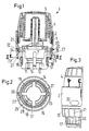
- Fig. 1
- ein en Längsschnitt durch einen Heizkörperventil-Thermostataufsatz.
- Fig. 2
- einen Schnitt II-II nach Fig. 1,
- Fig. 3
- eine Außenansicht des Aufsatzes,
- Fig. 4
- den Thermostataufsatz im montierten Zustand an einem Heizkörperventil und
- Fig. 5
- eine abgewandelte Ausführungsform.
- Fig. 1
- a longitudinal section through a radiator valve thermostat attachment.
- Fig. 2
- 2 shows a section II-II according to FIG. 1,
- Fig. 3
- an external view of the essay,
- Fig. 4
- the thermostat attachment when installed on a radiator valve and
- Fig. 5
- a modified embodiment.
Ein Heizkörperventil-Steueraufsatz ist im vorliegenden
Ausführungsbeispiel als Thermostataufsatz 1 ausgebildet
mit einem Gehäuse 2, in dem ein Thermostatelement 3 angeordnet
ist. Die axiale Position des Thermostatelements
3 kann mit Hilfe eines Drehgriffs 4 verändert
werden, der mit dem Gehäuse über ein Gewinde 5 verbunden
ist. Das Thermostatelement 3 wirkt über ein Betätigungsglied
6 auf eine Stößelfläche 7, an der im montierten
Zustand (Fig. 4) ein Stößel 8 eines Heizkörperventils
9 anliegt. Je weiter der Stößel 8 eingedrückt
wird, desto stärker drosselt das Heizkörperventil 9.A radiator valve control attachment is in the present
Embodiment designed as a thermostat attachment 1
with a
Selbstverständlich kann das Ventil auch zur Steuerung einer Heizfläche bei einer Fußbodenheizung verwendet werden.Of course, the valve can also be used for control a heating surface used in underfloor heating become.
Zur Befestigung des Thermostataufsatzes 1 am Ventil 9
ist ein Aufsatzstutzen 10 mit einer Eingriffsgeometrie
11 vorgesehen. Die Eingriffsgeometrie 11 weist beispielsweise
einen nach innen ragenden Vorsprung 12 auf,
der hinter einem entsprechenden Gegenvorsprung 13 am
Heizkörperventil 9 zur Anlage gebracht werden kann. Der
Aufsatzstutzen 11 weist in Umfangsrichtung verteilt
vier axial verlaufende Schlitze 14 auf, die zwischen
sich Beine 15 bilden, die aufgrund der Schlitze 14 radial
etwas nach außen federn können, um die Vorsprünge
12, 13 aneinander vorbeiführen zu können.To attach the thermostat attachment 1 to the valve 9
is an
Auf der Außenseite des Aufsatzstutzens 10 ist ein Außengewinde
16 angebracht, auf das eine Überwurfmutter
17 geschraubt ist. Das Außengewinde 16 erstreckt sich
bis zum Gehäuse 2, so daß die Überwurfmutter 17 auf der
gesamten Länge des Aufsatzstutzens 10 in jeder gewünschten
Position festgelegt werden kann. Sie kann also
beispielsweise bis zum Gehäuse 2 geschraubt werden,
so daß sie beim Aufsetzen des Thermostataufsatzes 1 auf
das Ventil 9 das Ausfedern der Beine 15 nicht behindert.There is an external thread on the outside of the
Im montierten Zustand (Fig. 4), d.h. dann, wenn die Überwurfmutter
17 so weit weg wie möglich vom Gehäuse 2
geschraubt worden ist, entsteht zwischen dem Gehäuse 2
und der Überwurfmutter 17 eine Lücke oder ein Spalt 18.
Dieser Spalt 18 ist durch einen Ring 19 abgedeckt, der
über eine Rastverbindung 20 so mit dem Gehäuse verbunden
ist, daß er in Axialrichtung festgelegt ist, gegenüber
dem Gehäuse 2 aber frei verdreht werden kann.
Hierzu weist das Gehäuse 2 eine umlaufende Nut 21 auf,
in die ein Vorsprung 22, der ebenfalls umlaufend ausgebildet
sein kann, am Ring 19 eingreift. Der Ring 19
kann seinerseits ebenfalls eine Nut 23 aufweisen, in
die ein Vorsprung 24 am Gehäuse eingreift. Durch entsprechend
abgeschrägte Flächen am Ring 19 und am Gehäuse
2 läßt sich der Ring 19 am Gehäuse 2 einrasten.
Hierzu wird er axial auf das Gehäuse 2 aufgeschoben. Er
weitet sich kurzzeitig radial auf und schnappt dann
wieder radial zusammen.In the assembled state (Fig. 4), i.e. then when the
Sämtliche Richtungsangaben beziehen sich auf die Rotationsachse
25 des Außengewindes 16.All directions refer to the axis of
Wie insbesondere aus Fig. 2 zu erkennen ist, weist die
Überwurfmutter 17 zwei radial nach außen ragende Vorsprünge
26 auf, während der Ring 19 zwei radial nach
innen ragende Vorsprünge 27 aufweist. Hierbei sind die
Lücken zwischen den beiden Vorsprüngen 27 in Umfangsrichtung
größer als die Breite der Vorsprünge 26 in Umfangsrichtung
und umgekehrt. In der in Fig. 2 dargestellten
Lage kann der Ring 19 bei Drehung im Uhrzeigersinn
die Überwurfmutter 17 mitnehmen, also ein Drehmoment
auf die Überwurfmutter übertragen. Wird der Ring
19 hingegen im Gegenuhrzeigersinn gedreht, dann ist eine
freie Drehung über einen Winkelbereich von 180° abzüglich
der Breite der beiden Vorsprünge 26, 27 möglich,
bevor der jeweilige Vorsprung 27 an den Vorsprung
26 zur Anlage kommt, den er bislang noch nicht beaufschlagt
hat. Diese Ausgestaltung hat zwei Vorteile. Zum
einen läßt sich die Winkelposition des Ringes 19 in gewissen
Grenzen nach erfolgter Montage wieder frei einstellen,
so daß man ein gefälliges Äußeres des Thermostataufsatzes
1 erzielen kann. Zum anderen wird zwischen
dem Ring 19 und der Überwurfmutter 17 ein Ringspalt 28
belassen, der nur durch die Vorsprünge 26, 27 unterbrochen
ist, ansonsten aber an beiden axialen Enden offen
ist. Dies erlaubt es, wie aus Fig. 4 zu erkennen ist,
daß eine durch einen Pfeil 29 dargestellte Luftströmung
den Teil des Ventils 9 umstreicht, der in Richtung auf
den Thermostataufsatz 1 vorsteht. Damit wird eine gewisse
Wärmemenge abgeführt, die dann nicht mehr das
Thermostatelement 2 beeinflussen kann. Die Beeinflussung
des Thermostatelements 3 erfolgt dann überwiegend
durch die Umgebungsluft bzw. durch Luft, die durch Öffnungen
30 an das Thermostatelement 3 gelangt.As can be seen in particular from FIG. 2, the
Natürlich können auch mehr als die beiden Vorsprungspaare
26, 27 vorgesehen sein. In allen Fällen sollte
aber gewährleistet sein, daß die Anordnung der Vorsprungspaare
26, 27 rotationssymmetrisch ist, so daß
die Einleitung eines Drehmoments vom Ring 19 auf die
Überwurfmutter 17 ebenfalls in Umfangsrichtung gleichmäßig
erfolgt.Of course, more can be done than the two pairs of
Man kann das Drehmoment vom Ring 19 auf die Überwurfmutter
17 auch auf eine andere Weise übertragen, beispielsweise
durch Reibung. Hierzu kann noch eine reibungserhöhende
Schicht auf der Innenseite des Ringes
oder der Außenseite der Mutter, beispielsweise aus Gummi,
vorgesehen sein. You can turn the torque from the
Aus Fig. 3 ist zu erkennen, daß der Ring 19 auf seiner
Umfangsfläche eine Reihe von radial vorstehenden und im
wesentlichen axial verlaufenden Stegen 31 aufweist, die
als Drehmomentangriffsflächen dienen. Diese Stege 31
haben in Umfangsrichtung im wesentlichen die gleiche
Breite wie entsprechende Stege 32, die als Drehmomentangriffsflächen
auf der Überwurfmutter 17 verwendet
werden. Man kann dann gegebenenfalls durch Verdrehen
des Ringes 19 die Stege 31, 32 in Ausrichtung zueinander
bringen, um das optische Erscheinungsbild zu
verbessern. Mann kann auch mit einem einzigen Werkzeug
sowohl den Ring 19 als auch die Überwurfmutter 17 verdrehen,
wenn diese nach erfolgter Drehung des Ringes 19
weit genug aus dem Ring 19 vorsteht.From Fig. 3 it can be seen that the
Aus Fig. 1 ist zu erkennen, daß die Vorsprünge 27 am
Ring eine so große axiale Erstreckung aufweisen, daß
die Überwurfmutter 17 über ihren gesamten Bewegungsbereich
mit Hilfe des Ringes 19 gedreht werden kann. Die
Vorsprünge 26 bleiben dabei im gesamten Bewegungsbereich
innerhalb des Ringes 19, so daß sie nach außen
nicht optisch störend in Erscheinung treten.From Fig. 1 it can be seen that the
Fig. 5 zeigt eine geringfügig abgewandelte Ausführungsform.
Hinzugekommen ist lediglich, daß der Ring 19'
Öffnungen 33 aufweist, durch die der Luftstrom 29' treten
kann, um das Ventil 9 zu kühlen bzw. Wärme abzuführen.
Natürlich ist es zusätzlich möglich, daß Luft
durch den Ringspalt 28 tritt. Dieser Luftpfad wurde aus
Gründen der Übersicht nicht mit eingezeichnet. Die Öffnungen
33 können nun durch die freie Verdrehbarkeit des
Ringes 19' gegenüber dem Gehäuse 2 und der Überwurfmutter
17 so ausgerichtet werden, daß sie vertikal übereinanderliegen.
In dieser Ausrichtung ist die Durchströmung
am günstigsten.5 shows a slightly modified embodiment.
All that has been added is that the ring 19 '
Has
Claims (12)
Applications Claiming Priority (2)
| Application Number | Priority Date | Filing Date | Title |
|---|---|---|---|
| DE19917780 | 1999-04-20 | ||
| DE19917780A DE19917780C1 (en) | 1999-04-20 | 1999-04-20 | Radiator valve control unit |
Publications (3)
| Publication Number | Publication Date |
|---|---|
| EP1046974A2 true EP1046974A2 (en) | 2000-10-25 |
| EP1046974A3 EP1046974A3 (en) | 2001-11-28 |
| EP1046974B1 EP1046974B1 (en) | 2005-05-18 |
Family
ID=7905177
Family Applications (1)
| Application Number | Title | Priority Date | Filing Date |
|---|---|---|---|
| EP00201025A Expired - Lifetime EP1046974B1 (en) | 1999-04-20 | 2000-03-21 | Actuating device for a radiator valve |
Country Status (9)
| Country | Link |
|---|---|
| EP (1) | EP1046974B1 (en) |
| CN (1) | CN1143086C (en) |
| AT (1) | ATE295973T1 (en) |
| CZ (1) | CZ294403B6 (en) |
| DE (1) | DE19917780C1 (en) |
| ES (1) | ES2242577T3 (en) |
| PL (1) | PL194830B1 (en) |
| RU (1) | RU2182686C2 (en) |
| UA (1) | UA59414C2 (en) |
Cited By (1)
| Publication number | Priority date | Publication date | Assignee | Title |
|---|---|---|---|---|
| EP1235128A2 (en) * | 2001-02-27 | 2002-08-28 | Behr Thermot-tronik GmbH | Means for applying an actuator or a thermostat head on a valve |
Families Citing this family (5)
| Publication number | Priority date | Publication date | Assignee | Title |
|---|---|---|---|---|
| DE20302855U1 (en) * | 2003-02-21 | 2003-06-12 | F W Oventrop Gmbh & Co Kg | Method fitting control valve to heating or cooling system has an security sleeve fitted over the securing nut to prevent unauthorised dismantling |
| DE102004032517B4 (en) * | 2004-05-18 | 2006-09-07 | F.W. Oventrop Gmbh & Co. Kg | thermostat |
| CN100467923C (en) * | 2004-05-18 | 2009-03-11 | F·W·奥文特罗普有限责任两合公司 | Thermostat |
| CN101625050B (en) * | 2008-07-10 | 2011-06-29 | 天佰立(北京)新技术发展有限公司 | Temperature controlling valve capable of cleaning valve core on line |
| CN104763840A (en) * | 2015-03-17 | 2015-07-08 | 刘银明 | High pressure water pipe depressurizing valve rotator |
Citations (5)
| Publication number | Priority date | Publication date | Assignee | Title |
|---|---|---|---|---|
| FR1554407A (en) * | 1967-03-23 | 1969-01-17 | ||
| DE2905307A1 (en) * | 1979-02-12 | 1980-08-21 | Heimeier Gmbh Metall Theodor | Heating valve thermostat head - has element housing turned by tool inserted through cap end |
| US4232817A (en) * | 1977-08-17 | 1980-11-11 | Braukmann Armaturen Ag | Adjustment control for a thermostatic valve |
| DE4442402C1 (en) * | 1994-11-30 | 1996-04-18 | Oventrop Sohn Kg F W | Thermostat head for heating valve |
| EP0859303A1 (en) * | 1997-02-14 | 1998-08-19 | Pegler Limited | Thermostatic valve control head |
-
1999
- 1999-04-20 DE DE19917780A patent/DE19917780C1/en not_active Expired - Lifetime
-
2000
- 2000-03-21 ES ES00201025T patent/ES2242577T3/en not_active Expired - Lifetime
- 2000-03-21 AT AT00201025T patent/ATE295973T1/en active
- 2000-03-21 PL PL339178A patent/PL194830B1/en unknown
- 2000-03-21 EP EP00201025A patent/EP1046974B1/en not_active Expired - Lifetime
- 2000-04-18 UA UA2000042235A patent/UA59414C2/en unknown
- 2000-04-19 RU RU2000109488/06A patent/RU2182686C2/en not_active IP Right Cessation
- 2000-04-19 CN CNB001067915A patent/CN1143086C/en not_active Expired - Fee Related
- 2000-04-20 CZ CZ20001456A patent/CZ294403B6/en not_active IP Right Cessation
Patent Citations (5)
| Publication number | Priority date | Publication date | Assignee | Title |
|---|---|---|---|---|
| FR1554407A (en) * | 1967-03-23 | 1969-01-17 | ||
| US4232817A (en) * | 1977-08-17 | 1980-11-11 | Braukmann Armaturen Ag | Adjustment control for a thermostatic valve |
| DE2905307A1 (en) * | 1979-02-12 | 1980-08-21 | Heimeier Gmbh Metall Theodor | Heating valve thermostat head - has element housing turned by tool inserted through cap end |
| DE4442402C1 (en) * | 1994-11-30 | 1996-04-18 | Oventrop Sohn Kg F W | Thermostat head for heating valve |
| EP0859303A1 (en) * | 1997-02-14 | 1998-08-19 | Pegler Limited | Thermostatic valve control head |
Cited By (2)
| Publication number | Priority date | Publication date | Assignee | Title |
|---|---|---|---|---|
| EP1235128A2 (en) * | 2001-02-27 | 2002-08-28 | Behr Thermot-tronik GmbH | Means for applying an actuator or a thermostat head on a valve |
| EP1235128A3 (en) * | 2001-02-27 | 2003-12-03 | Behr Thermot-tronik GmbH | Means for applying an actuator or a thermostat head on a valve |
Also Published As
| Publication number | Publication date |
|---|---|
| CZ20001456A3 (en) | 2001-05-16 |
| EP1046974B1 (en) | 2005-05-18 |
| CN1143086C (en) | 2004-03-24 |
| ATE295973T1 (en) | 2005-06-15 |
| EP1046974A3 (en) | 2001-11-28 |
| CN1271080A (en) | 2000-10-25 |
| DE19917780C1 (en) | 2001-01-04 |
| PL194830B1 (en) | 2007-07-31 |
| RU2182686C2 (en) | 2002-05-20 |
| PL339178A1 (en) | 2000-10-23 |
| CZ294403B6 (en) | 2004-12-15 |
| ES2242577T3 (en) | 2005-11-16 |
| UA59414C2 (en) | 2003-09-15 |
Similar Documents
| Publication | Publication Date | Title |
|---|---|---|
| EP1215401A2 (en) | Device for connecting structural components | |
| EP1180605A1 (en) | Device for connecting structural components | |
| DE202016107404U1 (en) | Reset for the piston of the wheel brake cylinder | |
| DE4318816C1 (en) | Safety device for a thermostat | |
| DE4344773A1 (en) | Thermostat attachment for radiator valves | |
| EP1903268A2 (en) | Adjusting handle for a water valve | |
| EP0530471A1 (en) | Actuating device for a mixing valve | |
| EP1046974B1 (en) | Actuating device for a radiator valve | |
| WO2018054785A1 (en) | Tolerance compensating element | |
| DE2527132C3 (en) | Connection device for a radiator | |
| DE102005060120B4 (en) | Radiator Valve Installation | |
| EP0683341B1 (en) | Sanitary armature | |
| DE102007018339B3 (en) | Spraying device for automated spraying, e.g. used with robots, has a casing and a covering plate with an adjusting device to seal the casing | |
| EP0552452B1 (en) | Actuating device for a mixing valve | |
| DE10153988A1 (en) | Actuator for a mixing valve | |
| EP1102142B1 (en) | Valve, in particular a thermostatic valve for heating systems | |
| EP0496103B1 (en) | Sanitary valve with swivelling spout | |
| DE2932884C2 (en) | Thermostat attachment for a radiator valve | |
| DE102004004636B4 (en) | Thermostatic valve top housing | |
| DE10236572B4 (en) | Handle attachment for sanitary fittings | |
| DE19739109C2 (en) | Radiator valve | |
| EP3755930B1 (en) | Actuating drive for a valve, and arrangement having a valve of this type, and method for the assembly thereof | |
| DE4242664A1 (en) | Thermostat locking nut cover on heating valves | |
| DE2852820C2 (en) | Thermostatic head for heating valves | |
| DE10358771B4 (en) | Valve with an operating handle |
Legal Events
| Date | Code | Title | Description |
|---|---|---|---|
| PUAI | Public reference made under article 153(3) epc to a published international application that has entered the european phase |
Free format text: ORIGINAL CODE: 0009012 |
|
| AK | Designated contracting states |
Kind code of ref document: A2 Designated state(s): AT BE CH CY DE DK ES FI FR GB GR IE IT LI LU MC NL PT SE |
|
| AX | Request for extension of the european patent |
Free format text: AL;LT;LV;MK;RO;SI |
|
| PUAL | Search report despatched |
Free format text: ORIGINAL CODE: 0009013 |
|
| AK | Designated contracting states |
Kind code of ref document: A3 Designated state(s): AT BE CH CY DE DK ES FI FR GB GR IE IT LI LU MC NL PT SE |
|
| AX | Request for extension of the european patent |
Free format text: AL;LT;LV;MK;RO;SI |
|
| 17P | Request for examination filed |
Effective date: 20011220 |
|
| AKX | Designation fees paid |
Free format text: AT BE CH CY DE DK ES FI FR GB GR IE IT LI LU MC NL PT SE |
|
| 17Q | First examination report despatched |
Effective date: 20021107 |
|
| GRAP | Despatch of communication of intention to grant a patent |
Free format text: ORIGINAL CODE: EPIDOSNIGR1 |
|
| GRAS | Grant fee paid |
Free format text: ORIGINAL CODE: EPIDOSNIGR3 |
|
| RBV | Designated contracting states (corrected) |
Designated state(s): AT BE CH CY DK ES FI FR GB GR IE IT LI LU MC NL PT SE |
|
| GRAA | (expected) grant |
Free format text: ORIGINAL CODE: 0009210 |
|
| REG | Reference to a national code |
Ref country code: DE Ref legal event code: 8566 |
|
| AK | Designated contracting states |
Kind code of ref document: B1 Designated state(s): AT BE CH CY DK ES FI FR GB GR IE IT LI LU MC NL PT SE |
|
| PG25 | Lapsed in a contracting state [announced via postgrant information from national office to epo] |
Ref country code: IE Free format text: LAPSE BECAUSE OF FAILURE TO SUBMIT A TRANSLATION OF THE DESCRIPTION OR TO PAY THE FEE WITHIN THE PRESCRIBED TIME-LIMIT Effective date: 20050518 Ref country code: NL Free format text: LAPSE BECAUSE OF FAILURE TO SUBMIT A TRANSLATION OF THE DESCRIPTION OR TO PAY THE FEE WITHIN THE PRESCRIBED TIME-LIMIT Effective date: 20050518 Ref country code: FI Free format text: LAPSE BECAUSE OF FAILURE TO SUBMIT A TRANSLATION OF THE DESCRIPTION OR TO PAY THE FEE WITHIN THE PRESCRIBED TIME-LIMIT Effective date: 20050518 |
|
| REG | Reference to a national code |
Ref country code: GB Ref legal event code: FG4D Free format text: NOT ENGLISH |
|
| REG | Reference to a national code |
Ref country code: CH Ref legal event code: EP |
|
| REG | Reference to a national code |
Ref country code: IE Ref legal event code: FG4D Free format text: LANGUAGE OF EP DOCUMENT: GERMAN |
|
| PG25 | Lapsed in a contracting state [announced via postgrant information from national office to epo] |
Ref country code: GR Free format text: LAPSE BECAUSE OF FAILURE TO SUBMIT A TRANSLATION OF THE DESCRIPTION OR TO PAY THE FEE WITHIN THE PRESCRIBED TIME-LIMIT Effective date: 20050818 Ref country code: DK Free format text: LAPSE BECAUSE OF FAILURE TO SUBMIT A TRANSLATION OF THE DESCRIPTION OR TO PAY THE FEE WITHIN THE PRESCRIBED TIME-LIMIT Effective date: 20050818 |
|
| REG | Reference to a national code |
Ref country code: SE Ref legal event code: TRGR |
|
| GBT | Gb: translation of ep patent filed (gb section 77(6)(a)/1977) |
Effective date: 20050816 |
|
| PG25 | Lapsed in a contracting state [announced via postgrant information from national office to epo] |
Ref country code: PT Free format text: LAPSE BECAUSE OF FAILURE TO SUBMIT A TRANSLATION OF THE DESCRIPTION OR TO PAY THE FEE WITHIN THE PRESCRIBED TIME-LIMIT Effective date: 20051024 |
|
| REG | Reference to a national code |
Ref country code: ES Ref legal event code: FG2A Ref document number: 2242577 Country of ref document: ES Kind code of ref document: T3 |
|
| NLV1 | Nl: lapsed or annulled due to failure to fulfill the requirements of art. 29p and 29m of the patents act | ||
| REG | Reference to a national code |
Ref country code: IE Ref legal event code: FD4D |
|
| PLBE | No opposition filed within time limit |
Free format text: ORIGINAL CODE: 0009261 |
|
| STAA | Information on the status of an ep patent application or granted ep patent |
Free format text: STATUS: NO OPPOSITION FILED WITHIN TIME LIMIT |
|
| ET | Fr: translation filed | ||
| PG25 | Lapsed in a contracting state [announced via postgrant information from national office to epo] |
Ref country code: BE Free format text: LAPSE BECAUSE OF NON-PAYMENT OF DUE FEES Effective date: 20060331 Ref country code: MC Free format text: LAPSE BECAUSE OF NON-PAYMENT OF DUE FEES Effective date: 20060331 Ref country code: LU Free format text: LAPSE BECAUSE OF NON-PAYMENT OF DUE FEES Effective date: 20060331 Ref country code: CH Free format text: LAPSE BECAUSE OF NON-PAYMENT OF DUE FEES Effective date: 20060331 Ref country code: LI Free format text: LAPSE BECAUSE OF NON-PAYMENT OF DUE FEES Effective date: 20060331 |
|
| 26N | No opposition filed |
Effective date: 20060221 |
|
| REG | Reference to a national code |
Ref country code: CH Ref legal event code: PL |
|
| PGFP | Annual fee paid to national office [announced via postgrant information from national office to epo] |
Ref country code: ES Payment date: 20070417 Year of fee payment: 8 |
|
| BERE | Be: lapsed |
Owner name: DANFOSS A/S Effective date: 20060331 |
|
| PG25 | Lapsed in a contracting state [announced via postgrant information from national office to epo] |
Ref country code: CY Free format text: LAPSE BECAUSE OF FAILURE TO SUBMIT A TRANSLATION OF THE DESCRIPTION OR TO PAY THE FEE WITHIN THE PRESCRIBED TIME-LIMIT Effective date: 20050518 |
|
| REG | Reference to a national code |
Ref country code: ES Ref legal event code: FD2A Effective date: 20080322 |
|
| PG25 | Lapsed in a contracting state [announced via postgrant information from national office to epo] |
Ref country code: ES Free format text: LAPSE BECAUSE OF NON-PAYMENT OF DUE FEES Effective date: 20080322 |
|
| PGFP | Annual fee paid to national office [announced via postgrant information from national office to epo] |
Ref country code: AT Payment date: 20110228 Year of fee payment: 12 Ref country code: IT Payment date: 20110316 Year of fee payment: 12 |
|
| REG | Reference to a national code |
Ref country code: AT Ref legal event code: MM01 Ref document number: 295973 Country of ref document: AT Kind code of ref document: T Effective date: 20120321 |
|
| PG25 | Lapsed in a contracting state [announced via postgrant information from national office to epo] |
Ref country code: AT Free format text: LAPSE BECAUSE OF NON-PAYMENT OF DUE FEES Effective date: 20120321 |
|
| PG25 | Lapsed in a contracting state [announced via postgrant information from national office to epo] |
Ref country code: IT Free format text: LAPSE BECAUSE OF NON-PAYMENT OF DUE FEES Effective date: 20120321 |
|
| REG | Reference to a national code |
Ref country code: FR Ref legal event code: PLFP Year of fee payment: 16 |
|
| REG | Reference to a national code |
Ref country code: FR Ref legal event code: PLFP Year of fee payment: 17 |
|
| REG | Reference to a national code |
Ref country code: FR Ref legal event code: PLFP Year of fee payment: 18 |
|
| REG | Reference to a national code |
Ref country code: FR Ref legal event code: PLFP Year of fee payment: 19 |
|
| PGFP | Annual fee paid to national office [announced via postgrant information from national office to epo] |
Ref country code: GB Payment date: 20180321 Year of fee payment: 19 |
|
| PGFP | Annual fee paid to national office [announced via postgrant information from national office to epo] |
Ref country code: FR Payment date: 20180226 Year of fee payment: 19 Ref country code: SE Payment date: 20180313 Year of fee payment: 19 |
|
| REG | Reference to a national code |
Ref country code: SE Ref legal event code: EUG |
|
| PG25 | Lapsed in a contracting state [announced via postgrant information from national office to epo] |
Ref country code: SE Free format text: LAPSE BECAUSE OF NON-PAYMENT OF DUE FEES Effective date: 20190322 |
|
| GBPC | Gb: european patent ceased through non-payment of renewal fee |
Effective date: 20190321 |
|
| PG25 | Lapsed in a contracting state [announced via postgrant information from national office to epo] |
Ref country code: GB Free format text: LAPSE BECAUSE OF NON-PAYMENT OF DUE FEES Effective date: 20190321 |
|
| PG25 | Lapsed in a contracting state [announced via postgrant information from national office to epo] |
Ref country code: FR Free format text: LAPSE BECAUSE OF NON-PAYMENT OF DUE FEES Effective date: 20190331 |