EP1046762A2 - Supporting element for the frontal fastening of the longitudinal ends of a vaulted roof skylight - Google Patents
Supporting element for the frontal fastening of the longitudinal ends of a vaulted roof skylight Download PDFInfo
- Publication number
- EP1046762A2 EP1046762A2 EP00106653A EP00106653A EP1046762A2 EP 1046762 A2 EP1046762 A2 EP 1046762A2 EP 00106653 A EP00106653 A EP 00106653A EP 00106653 A EP00106653 A EP 00106653A EP 1046762 A2 EP1046762 A2 EP 1046762A2
- Authority
- EP
- European Patent Office
- Prior art keywords
- profile
- bearing element
- frame
- rungs
- plate
- Prior art date
- Legal status (The legal status is an assumption and is not a legal conclusion. Google has not performed a legal analysis and makes no representation as to the accuracy of the status listed.)
- Withdrawn
Links
- 230000000284 resting effect Effects 0.000 claims abstract 3
- 229920003023 plastic Polymers 0.000 description 6
- 238000005452 bending Methods 0.000 description 2
- 238000004873 anchoring Methods 0.000 description 1
- 230000000149 penetrating effect Effects 0.000 description 1
- 238000007789 sealing Methods 0.000 description 1
Images


Classifications
-
- E—FIXED CONSTRUCTIONS
- E04—BUILDING
- E04D—ROOF COVERINGS; SKY-LIGHTS; GUTTERS; ROOF-WORKING TOOLS
- E04D13/00—Special arrangements or devices in connection with roof coverings; Protection against birds; Roof drainage ; Sky-lights
- E04D13/03—Sky-lights; Domes; Ventilating sky-lights
- E04D13/032—Supports or connecting means for sky-lights of vaulted shape
-
- E—FIXED CONSTRUCTIONS
- E04—BUILDING
- E04D—ROOF COVERINGS; SKY-LIGHTS; GUTTERS; ROOF-WORKING TOOLS
- E04D3/00—Roof covering by making use of flat or curved slabs or stiff sheets
- E04D3/02—Roof covering by making use of flat or curved slabs or stiff sheets of plane slabs, slates, or sheets, or in which the cross-section is unimportant
- E04D3/06—Roof covering by making use of flat or curved slabs or stiff sheets of plane slabs, slates, or sheets, or in which the cross-section is unimportant of glass or other translucent material; Fixing means therefor
- E04D3/08—Roof covering by making use of flat or curved slabs or stiff sheets of plane slabs, slates, or sheets, or in which the cross-section is unimportant of glass or other translucent material; Fixing means therefor with metal glazing bars
- E04D2003/0868—Mutual connections and details of glazing bars
- E04D2003/0881—Mutual connections and details of glazing bars on the eaves of the roof
Definitions
- the invention relates to a bearing element for an end Attachment of the longitudinal ends of a barrel-shaped Light band of a roof structure according to the generic term of Claim 1.
- a bearing element of this type is, for example, from DE 35 33 144 A1 known.
- the invention deals with the problem of one if possible large area of such a bearing element for attachment use differently structured light strips can. Different light strips can be worn in particular regarding the height of their rungs and the height of the plate elements.
- the invention is based on the general idea that opposite the base profile swiveling angle profile of the bearing element to be designed so that different in this high rungs only in one facing the base profile Partial area rest on the second leg. In this area openings are provided in this second leg, through the screws to attach a rung to it Legs are feasible.
- the frame profile to accommodate the Plate elements is each an independent, to the plate thickness adapted part that with the second leg of the Profile angle is screwed.
- a gable bearing element for receiving a gable-side plate of a light band, attached at right angles to the bearing element according to claim 1 can be, is the subject of claim 5.
- Die In this version, the gable wall can be flush with the respective longitudinal end face of a bearing element according to claim Complete 1.
- the light strip 1 is composed of curved in detail transparent plate elements 4 made of plastic, the rest on curved rungs 5 and firmly connected to them are.
- the light strip 1 is made of curved side by side Built up plate elements 4, these plate elements limit 4 lying on a common rung 5 against each other, wherein the abutting area by an overlying, cover rail connected to the rung and serving as a seal 6 is sealed.
- the rungs 5 are supported on the bearing elements 2, with to whom they are firmly connected.
- the bearing elements 2 exist from a screwed to the frame 3 of the roof structure Base profile 7 on which an angle profile 8 can be pivoted about an axis parallel to the longitudinal extent of the frame 3 is articulated.
- the rungs are supported at this angle 8 5 of the light band 1.
- the angle profile 8 consists of a first leg 9, which is articulated with the base profile 7 is connected and a second leg 10 which is rectangular protrudes from the first leg 9.
- the second leg 10 lies on one end face of the rungs 5 and is via screws 11 which through openings 12 in the grab the second leg 10 with the adjacent one Rung 5 firmly connected.
- the screws 11 engage within the rungs 5 into the screw channels 13 provided there.
- b clamping angle 16 is provided, which are anchored within the rungs 5 and the screwed to the cover rails 6 via clamping screws 17 are.
- the anchoring of the clamping angle 16 within the Rungs 5 is given by the fact that the clamping angle 16 in receiving rails 18 provided within the rungs 5 are positively inserted. Grab the clamping screws 17 through openings within the clamping angle 16 in inside of the cover rails 6 provided screw channels 20.
- the production of a light band in the execution according to the 3a, b can be made as follows.
- the bearing elements 2 are on the opposite frames 3, between which the light band 1 is to be formed, permanently installed.
- the assembly takes place in such a way that the Swivel axis between the base profiles 7 and the profile angle 8 of the bearing elements 2 in the edge area of the frames 3 still lies in the area of the respective frame. This ensures that from the light strip on the bearing elements 2 transferred forces not on a freely projecting area of the base profile 7 can attack.
- This is not a special one Stiffening of a cantilevered base profile area necessary because the basic profile is subject to its high stress Areas on the frame 3 below are sufficient can support safely.
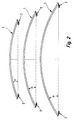
- the rungs 5 correspond to the barrel shape of the light strip pre-bent and have, for example, a radius of curvature of 2,800 mm.
- equally curved rungs 5 can be used as shown in FIG. 2.
- the bearing elements 2 can be used by the articulated there Compensate profile angle 8.
- the rungs 5 are in the permanently mounted bearing elements 2 inserted and screwed. Then it becomes flexible Plate element 4 on one of the two opposite Bearing elements 2 firmly anchored and after bending around the Rungs 5 then with the opposite bearing element 2 tense. In the case of panel elements to be juxtaposed 4 is followed accordingly.
- the cover rail 6 is each bent and at their two ends over one each Clamping angle 16 fixed relative to the assigned rung 5 tense. Sealing elements are located in the cover rail 6, with which a seal between cover rails 6 and assigned Plate elements 4 is ensured.
- the cover rails 6 are only anchored at the end to the respective rung 5.
- the frame profiles 14, in which the ends of the plate elements 4 are bordered, are in the occupied by the clamping angles 16 Areas interrupted.
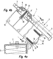
- the screw connection with the rung 5 ' is given by a screw 19, through an opening within the frame profile 14 'engages in a screw channel 20 of the rungs 5.
- the Screw channel 20 extends over the entire length of the Rungs 5 'and is U-shaped to the upper outside of the Rungs 5 designed open.
- the Decksehiene 6 is in the 4a, b, over their length several times through this cover rail penetrating screws 21 with the Rungs 5 'screwed, the screws 21 in the Engage screw channel 20 of rungs 5 '.
- the production of the light strip 1 according to FIGS. 4a, b is similar to that after the above-described execution and differs only in that already during bending the plate elements 4 and the cover rails 6 a screw the cover rails 6 on the rung 5 in the longitudinal direction the cover rails 6 progressively takes place.
- the rigidity of the rungs 5 according to FIGS. 3a, b can increased by inserting an additional inner profile 22 become.
- a flat, if possible transparent plastic plate 23 may be attached on a gable side of the light strip 1.
- a bearing element 2 'permanently mounted To attach this plastic plate 23 to an associated Frame 3 of the roof structure is on this frame 3 a bearing element 2 'permanently mounted.
- This bearing element 2 ' consists of a base profile firmly screwed to the frame 3 7 'and one suspended on its long side Gable frame profile 24.
- This bearing element shown in FIG. 1 2 ' enables a flush application in a simple manner the plastic plate 23 to the face of an adjacent one Bearing element 2.
- the connection of the gable frame profile 24 to the base profile 7 'of the bearing element 2' given by a kind of tongue and groove connection 25.
- the attachment the gable-side plastic plate 23 to the Rungs 5 and 5 ' are carried out in the usual way by a Gable angle 26 corresponding to FIG. 1.
- the advantage of the embodiment according to the invention is one modular structure of the light strip such that for different designed light strips as many of the same as possible Parts can be used.
Landscapes
- Engineering & Computer Science (AREA)
- Architecture (AREA)
- Civil Engineering (AREA)
- Structural Engineering (AREA)
- Roof Covering Using Slabs Or Stiff Sheets (AREA)
Abstract
Description
Die Erfindung betrifft ein Lagerelement für eine stirnseitige
Befestigung der Längsenden eines tonnenförmig gebogenen
Lichtbandes einer Dachkonstruktion nach dem Oberbegriff des
Patentanspruchs 1.The invention relates to a bearing element for an end
Attachment of the longitudinal ends of a barrel-shaped
Light band of a roof structure according to the generic term of
Ein Lagerelement dieser Art ist beispielsweise aus DE 35 33 144 A1 bekannt.A bearing element of this type is, for example, from DE 35 33 144 A1 known.
Die Erfindung beschäftigt sich mit dem Problem, einen möglichst großen Bereich eines solchen Lagerelementes zur Befestigung unterschiedlich aufgebauter Lichtbänder verwenden zu können. Unterschiedlich können zu tragende Lichtbänder insbesondere bezüglich der Höhe ihrer Sprossen sowie der Höhe der Plattenelemente sein.The invention deals with the problem of one if possible large area of such a bearing element for attachment use differently structured light strips can. Different light strips can be worn in particular regarding the height of their rungs and the height of the plate elements.
Eine Lösung zu dem vorstehenden Problem zeigt eine gattungsgemäße
Lagerelementausführung mit den kennzeichnenden Merkmalen
des Patentanspruchs 1 auf. A solution to the above problem is shown by a generic one
Bearing element design with the characteristic features
of
Zweckmäßige Verbindungen solcher Lagerelemente mit den zu
tragenden Elementen des Lichtbandes, nämlich dessen Sprossen
und der die Plattenelemente mit den Sprossen verbindenden
Rahmenprofilen sind Gegenstand der Patentansprüche 2 bis 4.Appropriate connections of such bearing elements with the
load-bearing elements of the light strip, namely its rungs
and that connecting the plate elements to the rungs
Frame profiles are the subject of
Die Erfindung beruht auf dem allgemeinen Gedanken, daß gegenüber dem Basisprofil schwenkbare Winkelprofil des Lagerelementes derart zu gestalten, daß in diesem unterschiedlich hohe Sprossen lediglich in einem dem Basisprofil zugewandten Teilbereich an dem zweiten Schenkel anliegen. In diesem Bereich sind in diesem zweiten Schenkel Öffnungen vorgesehen, durch die Schrauben zur Befestigung einer Sprosse an diesem Schenkel führbar sind. Das Rahmenprofil zur Aufnahme der Plattenelemente ist jeweils ein selbständiges, an die Plattendicke angepaßtes Teil, das mit dem zweiten Schenkel des Profilwinkels verschraubt wird.The invention is based on the general idea that opposite the base profile swiveling angle profile of the bearing element to be designed so that different in this high rungs only in one facing the base profile Partial area rest on the second leg. In this area openings are provided in this second leg, through the screws to attach a rung to it Legs are feasible. The frame profile to accommodate the Plate elements is each an independent, to the plate thickness adapted part that with the second leg of the Profile angle is screwed.
Je nachdem, wie die tonnenförmig gebogenen Plattenelemente an ihren Längsenden mit den Sprossen verbunden sind, sind die Längsenden der Plattenelemente einfassenden Rahmenprofile ausschließlich mit dem jeweils zweiten Schenkel des Profilwinkels eines Lagerelementes verbunden oder zusätzlich auch noch durch Schrauben an den längsseitigen Stirnenden an den Sprossen. Näheres hierzu wird noch bei der Beschreibung verschiedener Ausführungsbeispiele der Erfindung erläutert werden.Depending on how the barrel-shaped curved plate elements are connected at their longitudinal ends to the rungs frame profiles enclosing the longitudinal ends of the plate elements exclusively with the second leg of the Profile angle of a bearing element connected or in addition also by screwing on the long ends the rungs. More details will be given in the description Various embodiments of the invention explained become.
Eine vorteilhafte Ausgestaltung eines Giebel-Lagerelementes
zur Aufnahme einer giebelseitigen Platte eines Lichtbandes,
das rechtwinklig an das Lagerelement nach Anspruch 1 angesetzt
werden kann, ist Gegenstand des Patentanspruchs 5. Die
Giebelwand kann bei dieser Ausführung bündig mit der jeweils
längsseitigen Stirnseite eines Lagerelementes nach Anspruch
1 abschließen.An advantageous embodiment of a gable bearing element
for receiving a gable-side plate of a light band,
attached at right angles to the bearing element according to
Ausführungsbeispiele der Erfindung sind in der Zeichnung dargestellt.Embodiments of the invention are in the drawing shown.
In dieser zeigen
- Fig. 1
- eine perspektivische Ansicht auf ein in seiner Länge und Breite aufgebrochen dargestelltes Lichtband mit Lagerelementen auf bauseitigen Zargen,
- Fig. 2
- drei verschieden lange Lichtbänder in schematisch dargestellter Seitenansicht,
- Fig. 3a
- eine Seitenansicht eines die Längsstirnseiten des Lichtbandes tragenden Lagerelementes aus Fig. 1 in vergrößerter Darstellung,
- Fig. 3b
- einen Schnitt nach Linie IIIb-IIIb in Fig. 3a,
- Fig. 4a
- die Seitenansicht eines Lagerelementes nach Fig. 3a mit einer Anbindung an eine höhere Lichtband-Sprosse als in Fig. 3a,
- Fig. 4b
- einen Schnitt nach Linie IVb-IVb in Fig. 4a,
- Fig. 5
- einen Schnitt quer durch das Lichtband mit einer an einer Seitenfläche dargestellten Giebelplatte und deren bauseitige Lagerung.
- Fig. 1
- 1 shows a perspective view of a light strip, broken open in its length and width, with bearing elements on on-site frames,
- Fig. 2
- three light strips of different lengths in a schematically represented side view,
- Fig. 3a
- 2 shows an enlarged side view of a bearing element from FIG. 1 carrying the longitudinal end faces of the light strip,
- Fig. 3b
- 4 shows a section along line IIIb-IIIb in FIG. 3a,
- Fig. 4a
- 3 a shows a side view of a bearing element according to FIG. 3 a with a connection to a higher light strip rung than in FIG. 3 a,
- Fig. 4b
- 3 shows a section along line IVb-IVb in FIG. 4a,
- Fig. 5
- a section across the light band with a gable plate shown on a side surface and its on-site storage.
Innerhalb einer Dachkonstruktion befindet sich ein tonnenförmig
gebogenes Lichtband 1, das sich über Lagerelemente 2
und 2' auf Zargen 3 einer in der Zeichnung nicht dargestellten
Dachkonstruktion abstützt.There is a barrel shape inside a roof structure
Das Lichtband 1 setzt sich im einzelnen zusammen aus gebogenen
durchsichtigen Plattenelementen 4 aus Kunststoff, die
auf gebogenen Sprossen 5 aufliegen und fest mit diesen verbunden
sind.The
Ist das Lichtband 1 aus nebeneinanderliegenden gebogenen
Plattenelementen 4 aufgebaut, grenzen diese Plattenelemente
4 auf einer gemeinsamen Sprosse 5 aufliegend aneinander, wobei
der aneinanderstoßende Bereich durch eine aufliegende,
mit der Sprosse verbundene, als Dichtung dienende Deckschiene
6 gedichtet ist.The
Die Sprossen 5 stützen sich an den Lagerelementen 2 ab, mit
denen sie fest verbunden sind. Die Lagerelemente 2 bestehen
aus einem fest mit der Zarge 3 der Dachkonstruktion verschraubten
Basisprofil 7, an dem ein Winkelprofil 8 schwenkbar
um eine zur Längserstreckung der Zarge 3 parallele Achse
angelenkt ist. In diesem Winkel 8 stützen sich die Sprossen
5 des Lichtbandes 1 ab. Das Winkelprofil 8 besteht dabei aus
einem ersten Schenkel 9, der gelenkig mit dem Basisprofil 7
verbunden ist und einem zweiten Schenkel 10, der rechtwinklig
von dem ersten Schenkel 9 abragt. Der zweite Schenkel 10
liegt jeweils an einer endseitigen Stirnseite der Sprossen 5
an und ist über Schrauben 11, die durch Öffnungen 12 in den
zweiten Schenkel 10 greifen, mit der jeweils anliegenden
Sprosse 5 fest verbunden. Die Schrauben 11 greifen innerhalb
der Sprossen 5 in dort vorgesehene Schraubkanäle 13 ein.The
Die den Lagerelementen 2 zugeordneten Stirnseiten der Plattenelemente
4 sind in Rahmenprofilen 14 (Fig. 3a, b) eingefaßt,
die mit den zweiten Schenkeln 10 des Winkelprofiles 8
über einzelne Schrauben 15 verschraubt sind.The end faces of the plate elements assigned to the
Zur Befestigung der Deckschienen 6 an den Sprossen 5 sind
bei der Ausführung nach den Fig. 3a, b Spannwinkel 16 vorgesehen,
die innerhalb der Sprossen 5 verankert sind und die
über Spannschrauben 17 mit den Deckschienen 6 verschraubt
sind. Die Verankerung der Spannwinkel 16 innerhalb der
Sprossen 5 ist dadurch gegeben, daß die Spannwinkel 16 in
innerhalb der Sprossen 5 vorgesehene Aufnahmeschienen 18
formschlüssig eingeschoben sind. Die Spannschrauben 17 greifen
durch Öffnungen innerhalb des Spannwinkels 16 in innerhalb
der Deckschienen 6 vorgesehene Schraubkanäle 20.To attach the cover rails 6 to the
Die Herstellung eines Lichtbandes in der Ausführung nach den Fig. 3a, b kann wie folgt vorgenommen werden. The production of a light band in the execution according to the 3a, b can be made as follows.
Die Lagerelemente 2 werden auf den gegenüberliegenden Zargen
3, zwischen denen das Lichtband 1 ausgebildet werden soll,
fest montiert. Die Montage erfolgt dabei derart, daß die
Schwenkachse zwischen den Basisprofilen 7 und dem Profilwinkel
8 der Lagerelemente 2 im Kantenbereich der Zargen 3 noch
im Bereich der jeweiligen Zarge liegt. Dadurch wird sichergestellt,
daß die von dem Lichtband auf die Lagerelemente 2
übertragenen Kräfte nicht an einem frei auskragenden Bereich
des Basisprofils 7 angreifen können. Hierdurch ist keine besondere
Versteifung eines auskragenden Basisprofilbereiches
notwendig, da das Basisprofil sich in seinen kraftbeanspruchten
Bereichen auf der darunterliegenden Zarge 3 ausreichend
sicher abstützen kann.The
Die Sprossen 5 sind der Tonnenform des Lichtbandes entsprechend
vorgebogen und besitzen beispielsweise einen Krümmungsradius
von 2.800 mm. Für unterschiedlich lange Lichtbänder
1 können jeweils gleich gekrümmte Sprossen 5 verwendet
werden, wie dies in Fig. 2 gezeigt ist. Je nach unterschiedlicher
Länge des Lichtbandes verändern sich bei dem
Einsatz gleich gebogener Sprossen 5 die Einlaufwinkel α an
den Lagerelementen 2. Diese unterschiedlichen Einlaufwinkel
können die Lagerelemente 2 durch die dort schwenkbar angelenkten
Profilwinkel 8 ausgleichen.The
In die fest montierten Lagerelemente 2 werden die Sprossen 5
eingesetzt und verschraubt. Sodann wird jeweils ein biegsames
Plattenelement 4 an einem der beiden gegenüberliegenden
Lagerelemente 2 fest verankert und nach Biegung um die
Sprossen 5 sodann mit dem gegenüberliegenden Lagerelement 2
verspannt. Bei nebeneinander anzuardnenden Plattenelementen
4 wird entsprechend vorgegangen. Die Deckschiene 6 wird jeweils
gebogen und an ihren beiden Enden über jeweils einen
Spannwinkel 16 gegenüber der zugeordneten Sprosse 5 fest
verspannt. In der Deckschiene 6 befinden sich Dichtelemente,
mit denen eine Dichtung zwischen Deckschienen 6 und zugeordneten
Plattenelementen 4 sichergestellt ist. Bei der Ausführung
nach den Fig. 3a, b sind die Deckschienen 6 lediglich
endseitig mit der jeweils zugeordneten Sprosse 5 verankert.
Die Rahmenprofile 14, in denen die Enden der Plattenelemente
4 eingefaßt sind, sind in den von den Spannwinkeln 16 eingenommenen
Bereichen unterbrochen.The
Bei der Ausführung des Lichtbandes nach den Fig. 4a, b, die
für Spannweiten des Lichtbandes von beispielsweise über 3 m
geeignet ist, sind gegenüber der Ausführung nach den Fig.
3a, b höhere und damit tragstabilere Sprossen 5' eingesetzt.
Diese Sprossen 5' können von gegenüber der Ausführung nach
Fig. 3a, b unverändert bleibenden Lagerelementen 2 aufgenommen
und in ebenfalls gleicher Weise mit diesen verschraubt
werden. Hier wird gegenüber der Ausführung nach den Fig. 3a,
b lediglich ein verändertes Rahmenprofil 14' zur Aufnahme
des Plattenelementes 4 verwendet. Dieses Rahmenprofil 14'
ist einerseits wiederum mit dem zweiten Schenkel 10 des Winkelprofils
8 des Lagerelementes 2 und andererseits zusätzlich
noch direkt mit den Sprossen 5' verschraubt. Die Verschraubung
mit der Sprosse 5' ist durch eine Schraube 19 gegeben,
die durch eine Öffnung innerhalb des Rahmenprofils
14' in einen Schraubkanal 20 der Sprossen 5 eingreift. Der
Schraubkanal 20 erstreckt sich über die gesamte Länge der
Sprossen 5' und ist U-förmig zur oberen Außenseite der
Sprossen 5 offen ausgestaltet. Die Decksehiene 6 ist bei der
Ausführung nach den Fig. 4a, b, über deren Länge mehrfach
durch diese Deckschiene durchgreifende Schrauben 21 mit den
Sprossen 5' verschraubt, wobei die Schrauben 21 in den
Schraubkanal 20 der Sprossen 5' eingreifen.4a, b, the
for spans of the light band of, for example, over 3 m
is suitable, compared to the embodiment according to FIGS.
3a, b higher and thus more stable rungs 5 'used.
These rungs 5 'can be compared to the design according to
Fig. 3a, b
Die Herstellung des Lichtbandes 1 nach den Fig. 4a, b ist
ähnlich derjenigen nach der vorbeschriebenen Ausführung und
unterscheidet sich lediglich dadurch, daß bereits beim Biegen
der Plattenelemente 4 und der Deckschienen 6 eine Verschraubung
der Deckschienen 6 an der Sprosse 5 in Längsrichtung
der Deckschienen 6 fortschreitend erfolgt.The production of the
Die Steifigkeit der Sprossen 5 nach den Fig. 3a, b kann
durch das Einschieben eines Zusatz-Innenprofiles 22 erhöht
werden.The rigidity of the
An einer Giebelseite des Lichtbandes 1 kann eine ebene, möglichst
durchsichtige Kunststoffplatte 23 angebracht sein.
Zur Befestigung dieser Kunststoffplatte 23 an einer zugeordneten
Zarge 3 der Dachkonstruktion ist auf dieser Zarge 3
ein Lagerelement 2' fest montiert. Dieses Lagerelement 2'
besteht aus einem fest mit der Zarge 3 verschraubten Basisprofil
7' und einem an dessen Längsseite eingehängten
Giebelrahmenprofil 24. Dieses aus Fig. 1 ersichtliche Lagerelement
2' ermöglicht auf einfache Weise ein bündiges Anliegen
der Kunststoffplatte 23 an die Stirnseite eines benachbarten
Lagerelementes 2. Die Anbindung des Giebelrahmenprofiles
24 an das Basisprofil 7' des Lagerelementes 2' ist
durch eine Art Nut- und Federverbindung 25 gegeben. Die Befestigung
der giebelseitigen Kunststoffplatte 23 an die
Sprossen 5 bzw. 5' erfolgt in üblicher Weise durch einen
Giebelwinkel 26 entsprechend der Fig. 1.On a gable side of the
Ein aus mehreren gebogenen Plattenelementen 4 zusammengesetztes
Lichtband 1 ist in Fig. 5 dargestellt, wobei dort
nur eine Giebelseite vollständig gezeichnet ist.One composed of several curved plate elements 4
Der Vorteil der erfindungsgemäßen Ausführung besteht in einem modulartigen Aufbau des Lichtbandes derart, daß für unterschiedlich gestaltete Lichtbänder möglichst viele gleiche Teile einsetzbar sind. The advantage of the embodiment according to the invention is one modular structure of the light strip such that for different designed light strips as many of the same as possible Parts can be used.
- 11
- LichtbandLight band
- 2, 2'2, 2 '
- LagerelementBearing element
- 33rd
- Zargeframe
- 44th
- PlattenelementPlate element
- 5, 5'5, 5 '
- Sprosserung
- 66
- DeckschieneCover rail
- 7, 7'7, 7 '
- BasisprofilBase profile
- 88th
- WinkelprofilAngle profile
- 99
- erster Schenkelfirst leg
- 1010th
- zweiter Schenkelsecond leg
- 1111
- Schraubescrew
- 1212th
- Öffnungopening
- 1313
- SchraubenkanalScrew channel
- 14, 14'14, 14 '
- RahmenprofilFrame profile
- 1515
- Schraubescrew
- 1616
- SpannwinkelRake angle
- 1717th
- SpannschraubeClamping screw
- 1818th
- AufnahmeschieneMounting rail
- 1919th
- Schraubescrew
- 2020th
- SchraubkanalScrew channel
- 2121
- Schraubescrew
- 2222
- Zusatz-InnenprofilAdditional inner profile
- 2323
- Kunststoffplatte Plastic plate
- 2424th
- GiebelrahmenprofilGable frame profile
- 2525th
- Nut- und FederverbindungTongue and groove connection
- 2626
- GiebelwinkelGable angle
Claims (5)
dadurch gekennzeichnet,
daß der zweite Schenkel (10) ohne eine die Sprossen (5, 5') oder die Plattenelemente (4) hinterschnittartig umgreifende Auflagefläche ausgebildet ist.Bearing element (2, 2 ') for frontal fastening of the longitudinal ends of a barrel-shaped light strip (1) of a roof structure with at least one translucent, curved plate element (4) resting on rungs (5, 5') and from above on the edges of the Plate element (4), cover rails (6) resting on the rungs (5, 5 ') and frame elements (4, 4') which surround the plate element (4) and are supported by the bearing element, the bearing element consisting of a frame (3) mountable base profile (7) and an angle profile (8) pivotally attached to this base profile (7) with a first leg (9) articulated to the base profile (7) and a second leg (10) projecting therefrom, and furthermore the frame profiles (14) are each detachably connected to the second leg (10) of the angle profile (8),
characterized,
that the second leg (10) is formed without an undercut-like support surface encompassing the rungs (5, 5 ') or the plate elements (4).
dadurch gekennzeichnet,
daß in dem zweiten Schenkel (10) des Winkelprofils (8) Öffnungen für das Durchführen von Schrauben (11, 15) zur Befestigung einer Sprosse einerseits und eines Rahmenprofils (14, 14') zur Aufnahme des Längsendes eines Plattenelementes (4) andererseits vorgesehen sind.Bearing element according to claim 1.1
characterized,
that in the second leg (10) of the angle profile (8) openings for the passage of screws (11, 15) for fastening a rung on the one hand and a frame profile (14, 14 ') for receiving the longitudinal end of a plate element (4) on the other are provided .
dadurch gekennzeichnet,
daß das Rahmenprofil (14, 14') für das aufzunehmende Plattenelement (4) U-förmig ausgebildet ist und mit einem seitlich etwa rechtwinklig abragenden Steg zur Befestigung an dem zweiten Schenkel (10) des Winkelprofils (8) und/oder den Sprossen (5') versehen ist.Bearing element according to claim 1 or 2,
characterized,
that the frame profile (14, 14 ') for the plate element (4) to be received is U-shaped and with a laterally approximately perpendicularly projecting web for attachment to the second leg (10) of the angle profile (8) and / or the rungs (5 ') is provided.
dadurch gekennzeichnet,
daß die Befestigung eine Befestigung durch Schrauben (19, 15) ist.Bearing element according to one of the preceding claims,
characterized,
that the attachment is an attachment by screws (19, 15).
dadurch gekennzeichnet,
daß das Giebel-Lagerelement (2') aus einem auf einer Zarge (3) zu montierenden Giebel-Basisprofil (7') und einem an einer der Längsseiten des Basisprofils (7') eingehängten U-förmigen Rahmenprofil (24) zur Aufnahme der Giebel-Platte (23) besteht.Gable bearing element (2 ') for a right-angled connection to a bearing element (2) to be mounted on a frame (3) according to Claim 1 for holding a gable plate (23) which closes the light strip according to Claim 1,
characterized,
that the gable bearing element (2 ') from a gable base profile (7') to be mounted on a frame (3) and a U-shaped frame profile (24) suspended on one of the long sides of the base profile (7 ') for receiving the gable -Plate (23).
Applications Claiming Priority (2)
| Application Number | Priority Date | Filing Date | Title |
|---|---|---|---|
| DE19918631 | 1999-04-23 | ||
| DE1999118631 DE19918631A1 (en) | 1999-04-23 | 1999-04-23 | Bearing element for frontal fastening of the longitudinal ends of a barrel-shaped light strip of a roof structure |
Publications (2)
| Publication Number | Publication Date |
|---|---|
| EP1046762A2 true EP1046762A2 (en) | 2000-10-25 |
| EP1046762A3 EP1046762A3 (en) | 2001-05-23 |
Family
ID=7905715
Family Applications (1)
| Application Number | Title | Priority Date | Filing Date |
|---|---|---|---|
| EP00106653A Withdrawn EP1046762A3 (en) | 1999-04-23 | 2000-03-29 | Supporting element for the frontal fastening of the longitudinal ends of a vaulted roof skylight |
Country Status (2)
| Country | Link |
|---|---|
| EP (1) | EP1046762A3 (en) |
| DE (1) | DE19918631A1 (en) |
Cited By (2)
| Publication number | Priority date | Publication date | Assignee | Title |
|---|---|---|---|---|
| DE10320415A1 (en) * | 2003-05-07 | 2004-12-02 | Heinrich Strunz Gmbh | Trunking system with thermal foot and load-carrying jack |
| US7364007B2 (en) | 2004-01-08 | 2008-04-29 | Schlumberger Technology Corporation | Integrated acoustic transducer assembly |
Families Citing this family (2)
| Publication number | Priority date | Publication date | Assignee | Title |
|---|---|---|---|---|
| DE102022129042B3 (en) | 2022-11-03 | 2023-09-21 | additiveStream4D GmbH | Calibration system and calibration method for calibrating a building platform system in an additive manufacturing device |
| WO2024094255A1 (en) | 2022-11-03 | 2024-05-10 | additiveStream4D GmbH | Construction platform system for additive manufacturing |
Citations (1)
| Publication number | Priority date | Publication date | Assignee | Title |
|---|---|---|---|---|
| DE3533144A1 (en) | 1985-09-17 | 1987-04-02 | Eternit Ag | ARCHED ROOF OVERLIGHT ON A MOUNTING WREATH OR THE LIKE |
Family Cites Families (5)
| Publication number | Priority date | Publication date | Assignee | Title |
|---|---|---|---|---|
| NL7801905A (en) * | 1978-02-21 | 1979-08-23 | Jacobus Kuin | Pivoting coupling securing building element to a support - has beads threading one into the other lengthways |
| US4539783A (en) * | 1983-09-12 | 1985-09-10 | O'keeffe's, Inc. | Barrell vault skylight system |
| NL8501419A (en) * | 1985-05-17 | 1986-12-16 | Kuin Beheer B V | Mounting for double-walled transparent plastic panel on roof curb - has two L=sections with overlapping flanges on panel edge screwed together and spaced by rib to clamp other flanges on panel sides |
| FR2709780B1 (en) * | 1993-09-06 | 1997-07-11 | Guy Biguet | Range of frames for translucent walls and their manufacturing device. |
| FR2727165B1 (en) * | 1994-11-22 | 1996-12-27 | Audo Daniel | ASSEMBLY OF TRANSLUCENT PANELS WITH NON-VISIBLE EXTERNAL MECHANICAL FIXING |
-
1999
- 1999-04-23 DE DE1999118631 patent/DE19918631A1/en not_active Withdrawn
-
2000
- 2000-03-29 EP EP00106653A patent/EP1046762A3/en not_active Withdrawn
Patent Citations (1)
| Publication number | Priority date | Publication date | Assignee | Title |
|---|---|---|---|---|
| DE3533144A1 (en) | 1985-09-17 | 1987-04-02 | Eternit Ag | ARCHED ROOF OVERLIGHT ON A MOUNTING WREATH OR THE LIKE |
Cited By (2)
| Publication number | Priority date | Publication date | Assignee | Title |
|---|---|---|---|---|
| DE10320415A1 (en) * | 2003-05-07 | 2004-12-02 | Heinrich Strunz Gmbh | Trunking system with thermal foot and load-carrying jack |
| US7364007B2 (en) | 2004-01-08 | 2008-04-29 | Schlumberger Technology Corporation | Integrated acoustic transducer assembly |
Also Published As
| Publication number | Publication date |
|---|---|
| EP1046762A3 (en) | 2001-05-23 |
| DE19918631A1 (en) | 2000-10-26 |
Similar Documents
| Publication | Publication Date | Title |
|---|---|---|
| DE19536950C1 (en) | Shaped frame struts for construction of switch-cabinet housing | |
| EP0087647A1 (en) | Combined covering frame for skylights embedded side by side | |
| EP0429431A2 (en) | Façade covering by cavity wall elements with behind ventilation | |
| DE2844015C2 (en) | Sealing profile for roller shutter boxes | |
| DE19854452B4 (en) | Joinable rails for covering, bridging and / or bordering the edges of floor and / or wall coverings | |
| EP1046762A2 (en) | Supporting element for the frontal fastening of the longitudinal ends of a vaulted roof skylight | |
| DE9003900U1 (en) | Wood-metal frames for windows, doors, etc. | |
| DE2929215A1 (en) | Roof mounted solar heating system - uses rectangular frames made of sheet metal angles with strengthening ribs for heat collectors (AT 15.4.80) | |
| DE3340476A1 (en) | Vehicle window with a displaceable window pane | |
| DE3301940A1 (en) | WINDOWS OR DOORS WITH WOOD OR PLASTIC PANELS | |
| DE3426027C2 (en) | ||
| DE3943087C1 (en) | ||
| EP0477544B1 (en) | Filling piece for glazing beads | |
| DE2735975A1 (en) | Plastics or sheet metal gutter - has angled flat side pieces and base to resemble wooden construction | |
| DE9400115U1 (en) | Sealing profile | |
| DE8810264U1 (en) | Connecting corner strip | |
| EP0023969A2 (en) | Securing device for cambered plastic panels of roofings | |
| DE2914474C2 (en) | ||
| DE19918632A1 (en) | Hollow profile rung of a barrel-shaped light strip of a roof structure | |
| DE4321466A1 (en) | Case for a window | |
| DE8601903U1 (en) | Exposure device | |
| DE2509071C2 (en) | Awning box with bearing for a roll of fabric | |
| DE10043544B4 (en) | Sealing strip for a frame with an integrated sash | |
| DE2553801A1 (en) | Section assembled door or window frame - comprises homologous adjacent frame parts with clamp units engaging counter pieces | |
| EP1653579B1 (en) | Profiled rail for constructing a frame, particulary for an electrical cabinet |
Legal Events
| Date | Code | Title | Description |
|---|---|---|---|
| PUAI | Public reference made under article 153(3) epc to a published international application that has entered the european phase |
Free format text: ORIGINAL CODE: 0009012 |
|
| AK | Designated contracting states |
Kind code of ref document: A2 Designated state(s): AT CH DE LI |
|
| AX | Request for extension of the european patent |
Free format text: AL;LT;LV;MK;RO;SI |
|
| PUAL | Search report despatched |
Free format text: ORIGINAL CODE: 0009013 |
|
| AK | Designated contracting states |
Kind code of ref document: A3 Designated state(s): AT BE CH CY DE DK ES FI FR GB GR IE IT LI LU MC NL PT SE |
|
| AX | Request for extension of the european patent |
Free format text: AL;LT;LV;MK;RO;SI |
|
| RIC1 | Information provided on ipc code assigned before grant |
Free format text: 7E 04D 13/03 A, 7E 04D 3/08 B |
|
| 17P | Request for examination filed |
Effective date: 20010717 |
|
| AKX | Designation fees paid |
Free format text: AT CH DE LI |
|
| RAP1 | Party data changed (applicant data changed or rights of an application transferred) |
Owner name: J. EBERSPAECHER GMBH & CO. KG |
|
| 17Q | First examination report despatched |
Effective date: 20040126 |
|
| STAA | Information on the status of an ep patent application or granted ep patent |
Free format text: STATUS: THE APPLICATION IS DEEMED TO BE WITHDRAWN |
|
| 18D | Application deemed to be withdrawn |
Effective date: 20040608 |