EP1046535B1 - Dispositif de régulation thermique pour chaíne de traction d'un véhicule automobile - Google Patents
Dispositif de régulation thermique pour chaíne de traction d'un véhicule automobile Download PDFInfo
- Publication number
- EP1046535B1 EP1046535B1 EP00401108A EP00401108A EP1046535B1 EP 1046535 B1 EP1046535 B1 EP 1046535B1 EP 00401108 A EP00401108 A EP 00401108A EP 00401108 A EP00401108 A EP 00401108A EP 1046535 B1 EP1046535 B1 EP 1046535B1
- Authority
- EP
- European Patent Office
- Prior art keywords
- battery
- circuit
- control device
- previous
- temperature
- Prior art date
- Legal status (The legal status is an assumption and is not a legal conclusion. Google has not performed a legal analysis and makes no representation as to the accuracy of the status listed.)
- Expired - Lifetime
Links
Images
Classifications
-
- H—ELECTRICITY
- H01—ELECTRIC ELEMENTS
- H01M—PROCESSES OR MEANS, e.g. BATTERIES, FOR THE DIRECT CONVERSION OF CHEMICAL ENERGY INTO ELECTRICAL ENERGY
- H01M16/00—Structural combinations of different types of electrochemical generators
- H01M16/003—Structural combinations of different types of electrochemical generators of fuel cells with other electrochemical devices, e.g. capacitors, electrolysers
- H01M16/006—Structural combinations of different types of electrochemical generators of fuel cells with other electrochemical devices, e.g. capacitors, electrolysers of fuel cells with rechargeable batteries
-
- H—ELECTRICITY
- H01—ELECTRIC ELEMENTS
- H01M—PROCESSES OR MEANS, e.g. BATTERIES, FOR THE DIRECT CONVERSION OF CHEMICAL ENERGY INTO ELECTRICAL ENERGY
- H01M8/00—Fuel cells; Manufacture thereof
- H01M8/04—Auxiliary arrangements, e.g. for control of pressure or for circulation of fluids
- H01M8/04082—Arrangements for control of reactant parameters, e.g. pressure or concentration
- H01M8/04089—Arrangements for control of reactant parameters, e.g. pressure or concentration of gaseous reactants
-
- H—ELECTRICITY
- H01—ELECTRIC ELEMENTS
- H01M—PROCESSES OR MEANS, e.g. BATTERIES, FOR THE DIRECT CONVERSION OF CHEMICAL ENERGY INTO ELECTRICAL ENERGY
- H01M2250/00—Fuel cells for particular applications; Specific features of fuel cell system
- H01M2250/20—Fuel cells in motive systems, e.g. vehicle, ship, plane
-
- H—ELECTRICITY
- H01—ELECTRIC ELEMENTS
- H01M—PROCESSES OR MEANS, e.g. BATTERIES, FOR THE DIRECT CONVERSION OF CHEMICAL ENERGY INTO ELECTRICAL ENERGY
- H01M8/00—Fuel cells; Manufacture thereof
- H01M8/04—Auxiliary arrangements, e.g. for control of pressure or for circulation of fluids
- H01M8/04007—Auxiliary arrangements, e.g. for control of pressure or for circulation of fluids related to heat exchange
-
- Y—GENERAL TAGGING OF NEW TECHNOLOGICAL DEVELOPMENTS; GENERAL TAGGING OF CROSS-SECTIONAL TECHNOLOGIES SPANNING OVER SEVERAL SECTIONS OF THE IPC; TECHNICAL SUBJECTS COVERED BY FORMER USPC CROSS-REFERENCE ART COLLECTIONS [XRACs] AND DIGESTS
- Y02—TECHNOLOGIES OR APPLICATIONS FOR MITIGATION OR ADAPTATION AGAINST CLIMATE CHANGE
- Y02E—REDUCTION OF GREENHOUSE GAS [GHG] EMISSIONS, RELATED TO ENERGY GENERATION, TRANSMISSION OR DISTRIBUTION
- Y02E60/00—Enabling technologies; Technologies with a potential or indirect contribution to GHG emissions mitigation
- Y02E60/10—Energy storage using batteries
-
- Y—GENERAL TAGGING OF NEW TECHNOLOGICAL DEVELOPMENTS; GENERAL TAGGING OF CROSS-SECTIONAL TECHNOLOGIES SPANNING OVER SEVERAL SECTIONS OF THE IPC; TECHNICAL SUBJECTS COVERED BY FORMER USPC CROSS-REFERENCE ART COLLECTIONS [XRACs] AND DIGESTS
- Y02—TECHNOLOGIES OR APPLICATIONS FOR MITIGATION OR ADAPTATION AGAINST CLIMATE CHANGE
- Y02E—REDUCTION OF GREENHOUSE GAS [GHG] EMISSIONS, RELATED TO ENERGY GENERATION, TRANSMISSION OR DISTRIBUTION
- Y02E60/00—Enabling technologies; Technologies with a potential or indirect contribution to GHG emissions mitigation
- Y02E60/30—Hydrogen technology
- Y02E60/50—Fuel cells
-
- Y—GENERAL TAGGING OF NEW TECHNOLOGICAL DEVELOPMENTS; GENERAL TAGGING OF CROSS-SECTIONAL TECHNOLOGIES SPANNING OVER SEVERAL SECTIONS OF THE IPC; TECHNICAL SUBJECTS COVERED BY FORMER USPC CROSS-REFERENCE ART COLLECTIONS [XRACs] AND DIGESTS
- Y02—TECHNOLOGIES OR APPLICATIONS FOR MITIGATION OR ADAPTATION AGAINST CLIMATE CHANGE
- Y02T—CLIMATE CHANGE MITIGATION TECHNOLOGIES RELATED TO TRANSPORTATION
- Y02T90/00—Enabling technologies or technologies with a potential or indirect contribution to GHG emissions mitigation
- Y02T90/40—Application of hydrogen technology to transportation, e.g. using fuel cells
Definitions
- the present invention relates to a thermal regulation device for a motor vehicle battery.
- This device can be everything particularly used in an electric or hybrid vehicle comprising a fuel cell.
- the electrochemical reaction that occurs in a fuel cell between the oxygen of the air and hydrogen generates electric current and water.
- the electricity is stored partly in a buffer battery.
- hydrogen is often stored in a reservoir in liquid form at a temperature of about -250 ° C; however, it is necessary that the flow of hydrogen entering the cell is at a temperature above 0 ° C so to avoid any problem deicing in the fuel cell.
- DE 4040350 shows a device according to the preamble of claim 1.
- US-5,577,747 discloses a system in which the warming of hydrogen is supplied via a heat exchanger by a coolant of cooling of auxiliary components (oil, inverter).
- the vehicle's battery remains cooled by air, a technique that effective if the outside temperature remains below optimal operating temperature of the battery. Indeed, a too high operating temperature of the battery results in a loss of efficiency when charging or even an impossibility to charge the battery if the outside temperature is too high and / or a degradation of its life time and its autonomy.
- the air cooling mainly implement a mechanism of convective heat transfer, which involves a large temperature gradient near the walls and an increase in the characteristic time of the heat transfer which is translated by the storage of the heat produced in the heat capacity of the drums.
- the average thermal power generated in a battery of traction of an electric vehicle during a typical approximately the power required to bring the temperature from -250 ° C to + 10 ° C hydrogen flow temperature feeding a conventional fuel cell (typical average flow rate of the order of 0.2 g / s).
- the subject of the invention is a device for the thermal regulation of a traction chain of a vehicle according to the features of claim 1 equipped with a power generator, a battery and a generator supply fluid reservoir, said reservoir and generator being hydraulically connected by a supply circuit, characterized in that the generator supply circuit co-operates thermally with a battery cooling circuit.
- the circuit of cooling of the battery and the power circuit cooperate thermally via a heat exchanger.
- the circuit of cooling of the battery can be hydraulically connected via a circuit of diversion to a cooling circuit of accessories of the traction chain.
- the activation of the circuit deriving from the exceeding of a threshold of the temperature of the drums is a condition in which the activation of the circuit deriving from the exceeding of a threshold of the temperature of the drums.
- the circuit of cooling of the battery and the cooling circuit of the accessories are interconnected via a three-way valve controlled by a signal representative of the temperature of the battery.
- a resistance of heating is incorporated in the battery cooling circuit.
- a non-return valve is incorporated in the branch circuit.
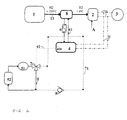
- the generator of power consists of a fuel cell supplied with air A and H2, via a feed circuit 11, at a temperature greater than 0 ° C to prevent icing of the fuel cell.
- Hydrogen is stored in liquid form at a temperature of about -250 ° C in the tank 1. Before being injected into the fuel cell, the hydrogen liquid is heated by a heat transfer fluid cooling a battery 4 at the level of a heat exchanger 8.
- the heat transfer fluid of the battery circulates in a circuit 61.
- a heating resistor 6 integrated in the circuit 61 makes it possible to heat the coolant when the temperature of the battery is insufficient, especially at startup.
- the group 3 is connected to fuel cell 2 and battery 4 respectively by electrical connections 31 and 32.
- a cooling circuit 5 of auxiliary elements 52 of vehicle such as for example an inverter, a compressor and a radiator 51.
- a coolant circulates in the circuit 5, the latter being connectable via a three-way valve 7.
- This valve 7 is controlled by a sensor 410 of temperature of the battery 4 via a link 41.
- the valve 7 and a non-return valve 9 ensure a complete seal between the circuits 5 and 71 when the two circuits must operate independently of one another.
- the solicitations to which the battery is subjected cause its internal heating which requires its cooling for the battery operates under optimal conditions of use.
- the two circuits 5 and 61 are isolated by the valve 7 and the valve 9.
- the heat taken from the battery by the fluid coolant circulating in the circuit 61 is then sufficient to ensure alone, at level of the exchanger 8, the passage of hydrogen to an enthalpy level sufficient to be usable by the battery 2.
- Auxiliary cooling 52 is then ensured only by the radiator 51.
- the combination of the two circuits 5 and 61 allows a heat transfer of auxiliary to hydrogen, which makes it possible to meet the constraints of use in battery temperature and warm enough hydrogen before entering the fuel cell.
- the two circuits 5 and 61 are isolated by the valve 7 and the valve 9 and the coolant of the circuit 61 is brought to a sufficient temperature to heat the hydrogen through the resistor 6 4. As soon as the temperature of the coolant at the inlet of the exchanger 8 will be sufficient, the resistor 6 will no longer be powered by the battery 4.
- the device according to the invention not only allows to cool effectively the battery by freeing itself from the constraint of the temperature of the air outside which is very penalizing for air cooling systems but again to heat the hydrogen regardless of the solicitation of the battery.
- the device according to the invention can be applied to any vehicle possessing a cold source at low temperature.
Landscapes
- Life Sciences & Earth Sciences (AREA)
- Engineering & Computer Science (AREA)
- Sustainable Development (AREA)
- Sustainable Energy (AREA)
- Chemical & Material Sciences (AREA)
- Chemical Kinetics & Catalysis (AREA)
- Electrochemistry (AREA)
- General Chemical & Material Sciences (AREA)
- Manufacturing & Machinery (AREA)
- Electric Propulsion And Braking For Vehicles (AREA)
- Fuel Cell (AREA)
Description
Claims (6)
- Dispositif de régulation thermique d'une chaíne de traction d'un véhicule équipé d'un générateur d'énergie électrique (2), d'une batterie (4) et d'un réservoir (1) de fluide d'alimentation du générateur, ledit réservoir (1) et générateur étant reliés hydrauliquement par un circuit d'alimentation (11), caractérisé en ce que le circuit d'alimentation du générateur coopère thermiquement avec un circuit de refroidissement (61) de la batterie via un échangeur (8) et le générateur (2) d'énergie électrique est une pile à combustible.
- Dispositif de régulation selon la revendication précédente, caractérisé en ce que le circuit de refroidissement (61) de la batterie (4) peut être relié hydrauliquement via un circuit de dérivation (71) à un circuit de refroidissement (5) d'accessoires de la chaíne de traction.
- Dispositif de régulation selon l'une quelconque des revendications précédentes, caractérisé en ce que l'activation du circuit de dérivation (71) résulte du dépassement d'un seuil de la température de la batterie (4).
- Dispositif de régulation selon la revendication précédente, caractérisé en ce que le circuit de refroidissement de la batterie et le circuit de refroidissement des accessoires sont interconnectés via une vanne trois voies (7) commandée par un signal représentatif de la température de la batterie.
- Dispositif de régulation selon l'une quelconque des revendications précédentes, caractérisé en ce qu'une résistance de chauffage (6) est incorporée dans le circuit de refroidissement de la batterie.
- Dispositif de régulation selon l'une quelconque des revendications précédentes, caractérisé en ce qu'un clapet anti-retour (9) est incorporé dans le circuit de dérivation (71).
Applications Claiming Priority (2)
| Application Number | Priority Date | Filing Date | Title |
|---|---|---|---|
| FR9905105 | 1999-04-22 | ||
| FR9905105A FR2792578B1 (fr) | 1999-04-22 | 1999-04-22 | Dispositif de regulation thermique pour chaine de traction d'un vehicule automobile |
Publications (2)
| Publication Number | Publication Date |
|---|---|
| EP1046535A1 EP1046535A1 (fr) | 2000-10-25 |
| EP1046535B1 true EP1046535B1 (fr) | 2005-03-02 |
Family
ID=9544742
Family Applications (1)
| Application Number | Title | Priority Date | Filing Date |
|---|---|---|---|
| EP00401108A Expired - Lifetime EP1046535B1 (fr) | 1999-04-22 | 2000-04-20 | Dispositif de régulation thermique pour chaíne de traction d'un véhicule automobile |
Country Status (4)
| Country | Link |
|---|---|
| EP (1) | EP1046535B1 (fr) |
| DE (1) | DE60018321T2 (fr) |
| ES (1) | ES2234535T3 (fr) |
| FR (1) | FR2792578B1 (fr) |
Families Citing this family (6)
| Publication number | Priority date | Publication date | Assignee | Title |
|---|---|---|---|---|
| JP4644704B2 (ja) * | 2007-11-14 | 2011-03-02 | アイシン精機株式会社 | 燃料電池システム |
| DE102013011057B4 (de) | 2013-07-02 | 2023-02-09 | Cellcentric Gmbh & Co. Kg | Kühlsystem für ein Brennstoffzellensystem |
| DE102017000802A1 (de) | 2017-01-28 | 2018-08-02 | Daimler Ag | Vorrichtung zur Erwärmung von Wasserstoff |
| CN109962313B (zh) * | 2017-12-14 | 2021-06-01 | 郑州宇通客车股份有限公司 | 一种燃料电池混合动力车辆及其低温启动控制方法、装置 |
| CN110635150B (zh) * | 2019-10-12 | 2020-10-27 | 中国科学院大连化学物理研究所 | 一种多燃料电池模块联用的热管理系统和方法 |
| KR20220080757A (ko) * | 2020-12-07 | 2022-06-15 | 현대자동차주식회사 | 연료전지-배터리 시스템 및 그 제어방법 |
Family Cites Families (2)
| Publication number | Priority date | Publication date | Assignee | Title |
|---|---|---|---|---|
| DE4040350C2 (de) * | 1990-12-17 | 2000-02-17 | Eckart Berling | Hybrid-Antriebsaggregat für KFZ bestehend aus photovoltaischen Zellen, Niedertemperatur- Supraleiter- Elektromotor/-Speicherspule und Flüssigwasserstoff- Verbrennungsmotor |
| JP3317560B2 (ja) | 1993-10-19 | 2002-08-26 | 本田技研工業株式会社 | 電動車両の電池冷却構造 |
-
1999
- 1999-04-22 FR FR9905105A patent/FR2792578B1/fr not_active Expired - Fee Related
-
2000
- 2000-04-20 ES ES00401108T patent/ES2234535T3/es not_active Expired - Lifetime
- 2000-04-20 DE DE60018321T patent/DE60018321T2/de not_active Expired - Lifetime
- 2000-04-20 EP EP00401108A patent/EP1046535B1/fr not_active Expired - Lifetime
Also Published As
| Publication number | Publication date |
|---|---|
| EP1046535A1 (fr) | 2000-10-25 |
| FR2792578B1 (fr) | 2001-05-25 |
| DE60018321D1 (de) | 2005-04-07 |
| ES2234535T3 (es) | 2005-07-01 |
| FR2792578A1 (fr) | 2000-10-27 |
| DE60018321T2 (de) | 2006-04-06 |
Similar Documents
| Publication | Publication Date | Title |
|---|---|---|
| FR2724875A1 (fr) | Dispositif pour chauffer l'habitacle d'un vehicule electrique | |
| FR2792259A1 (fr) | Dispositif de refroidissement pour vehicule electrique a pile a combustible | |
| EP1291949A2 (fr) | Système de pile à combustible, son méthode de commande et véhicule monté avec celui-ci | |
| FR2936980A1 (fr) | Vehicule automobile a moteur electrique comportant un circuit de refroidissement du circuit electronique de puissance connecte a un radiateur de chauffage de l'habitacle | |
| FR2934087A3 (fr) | Systeme et procede de refroidissement d'une batterie de vehicule electrique, batterie et station de refroidissement d'une batterie | |
| FR2966776A1 (fr) | Dispositif de conditionnement thermique d'une chaine de traction et d'un habitacle de vehicule. | |
| EP3899225B1 (fr) | Dispositif de gestion thermique d'un circuit de fluide caloporteur d'un véhicule hybride | |
| EP1046535B1 (fr) | Dispositif de régulation thermique pour chaíne de traction d'un véhicule automobile | |
| EP2108210B1 (fr) | Dispositif et procede de chauffage d'une batterie de vehicule hybride | |
| WO2021204684A1 (fr) | Agencement pour refroidir une pile à combustible et un moteur électrique de traction et/ou de propulsion de véhicule | |
| EP1255317A1 (fr) | Dispositif de gestion thermique d'un véhicule automobile | |
| EP1733446B1 (fr) | Dispositif et procede de refroidissement d'un module de puissance d'une pile a combustible | |
| EP2912395B1 (fr) | Module de refroidissement d'un moteur de véhicule automobile, et procédé de pilotage correspondant | |
| FR2784334A1 (fr) | Dispositif thermostatique de recuperation de la chaleur des gaz d'echappement d'un vehicule | |
| EP3849833B1 (fr) | Circuit de liquide caloporteur | |
| FR2813994A1 (fr) | Pile a combustible et procede de protection d'une telle pile contre le gel | |
| FR2962072A1 (fr) | Vehicule hybride comprenant un chargeur embarque | |
| FR2911092A1 (fr) | Systeme et procede de gestion thermique multifonction pour vehicule hybride | |
| FR3142125A1 (fr) | Système et procédé de gestion thermique d’un véhicule automobile comprenant une chaîne d’entraînement électrique et une pile à combustible | |
| EP4195335A1 (fr) | Système de gestion thermique d'un système hybride pile à combustible batterie rechargeable | |
| FR2868605A1 (fr) | Dispositif et procede de refroidissement d'un module de puissance d'une pile a combustible | |
| FR2805666A1 (fr) | Dispositif de refroidissement d'un vehicule electrique alimente par une pile a combustible | |
| FR2824785A1 (fr) | Dispositif et procede de recuperation de chaleur pour vehicule equipe d'une pile a combustible | |
| FR2865854A1 (fr) | Procede de mise en temperature d'un generateur electrique a pile a combustible et generateur electrique mettant en oeuvre ce procede. | |
| FR3128588A1 (fr) | Système de refroidissement d’une pile à combustible embarquée dans un véhicule, véhicule et méthode de régulation associés |
Legal Events
| Date | Code | Title | Description |
|---|---|---|---|
| PUAI | Public reference made under article 153(3) epc to a published international application that has entered the european phase |
Free format text: ORIGINAL CODE: 0009012 |
|
| AK | Designated contracting states |
Kind code of ref document: A1 Designated state(s): DE ES GB IT |
|
| AX | Request for extension of the european patent |
Free format text: AL;LT;LV;MK;RO;SI |
|
| 17P | Request for examination filed |
Effective date: 20010417 |
|
| AKX | Designation fees paid |
Free format text: DE ES GB IT |
|
| RAP1 | Party data changed (applicant data changed or rights of an application transferred) |
Owner name: RENAULT S.A.S. |
|
| 17Q | First examination report despatched |
Effective date: 20020816 |
|
| GRAP | Despatch of communication of intention to grant a patent |
Free format text: ORIGINAL CODE: EPIDOSNIGR1 |
|
| GRAS | Grant fee paid |
Free format text: ORIGINAL CODE: EPIDOSNIGR3 |
|
| GRAA | (expected) grant |
Free format text: ORIGINAL CODE: 0009210 |
|
| AK | Designated contracting states |
Kind code of ref document: B1 Designated state(s): DE ES GB IT |
|
| REG | Reference to a national code |
Ref country code: GB Ref legal event code: FG4D Free format text: NOT ENGLISH |
|
| REF | Corresponds to: |
Ref document number: 60018321 Country of ref document: DE Date of ref document: 20050407 Kind code of ref document: P |
|
| GBT | Gb: translation of ep patent filed (gb section 77(6)(a)/1977) |
Effective date: 20050511 |
|
| REG | Reference to a national code |
Ref country code: ES Ref legal event code: FG2A Ref document number: 2234535 Country of ref document: ES Kind code of ref document: T3 |
|
| PLBE | No opposition filed within time limit |
Free format text: ORIGINAL CODE: 0009261 |
|
| STAA | Information on the status of an ep patent application or granted ep patent |
Free format text: STATUS: NO OPPOSITION FILED WITHIN TIME LIMIT |
|
| 26N | No opposition filed |
Effective date: 20051205 |
|
| PGFP | Annual fee paid to national office [announced via postgrant information from national office to epo] |
Ref country code: ES Payment date: 20110426 Year of fee payment: 12 Ref country code: DE Payment date: 20110421 Year of fee payment: 12 |
|
| PGFP | Annual fee paid to national office [announced via postgrant information from national office to epo] |
Ref country code: GB Payment date: 20110421 Year of fee payment: 12 |
|
| PGFP | Annual fee paid to national office [announced via postgrant information from national office to epo] |
Ref country code: IT Payment date: 20110421 Year of fee payment: 12 |
|
| GBPC | Gb: european patent ceased through non-payment of renewal fee |
Effective date: 20120420 |
|
| PG25 | Lapsed in a contracting state [announced via postgrant information from national office to epo] |
Ref country code: GB Free format text: LAPSE BECAUSE OF NON-PAYMENT OF DUE FEES Effective date: 20120420 |
|
| REG | Reference to a national code |
Ref country code: DE Ref legal event code: R119 Ref document number: 60018321 Country of ref document: DE Effective date: 20121101 |
|
| PG25 | Lapsed in a contracting state [announced via postgrant information from national office to epo] |
Ref country code: IT Free format text: LAPSE BECAUSE OF NON-PAYMENT OF DUE FEES Effective date: 20120420 |
|
| REG | Reference to a national code |
Ref country code: ES Ref legal event code: FD2A Effective date: 20130716 |
|
| PG25 | Lapsed in a contracting state [announced via postgrant information from national office to epo] |
Ref country code: ES Free format text: LAPSE BECAUSE OF NON-PAYMENT OF DUE FEES Effective date: 20120421 |
|
| PG25 | Lapsed in a contracting state [announced via postgrant information from national office to epo] |
Ref country code: DE Free format text: LAPSE BECAUSE OF NON-PAYMENT OF DUE FEES Effective date: 20121101 |