EP1046215B1 - Electric motor fan wheel combination and method for the production thereof - Google Patents
Electric motor fan wheel combination and method for the production thereof Download PDFInfo
- Publication number
- EP1046215B1 EP1046215B1 EP99950472A EP99950472A EP1046215B1 EP 1046215 B1 EP1046215 B1 EP 1046215B1 EP 99950472 A EP99950472 A EP 99950472A EP 99950472 A EP99950472 A EP 99950472A EP 1046215 B1 EP1046215 B1 EP 1046215B1
- Authority
- EP
- European Patent Office
- Prior art keywords
- armature
- hub
- bearing
- fan impeller
- electric motor
- Prior art date
- Legal status (The legal status is an assumption and is not a legal conclusion. Google has not performed a legal analysis and makes no representation as to the accuracy of the status listed.)
- Expired - Lifetime
Links
Images

Classifications
-
- H—ELECTRICITY
- H02—GENERATION; CONVERSION OR DISTRIBUTION OF ELECTRIC POWER
- H02K—DYNAMO-ELECTRIC MACHINES
- H02K7/00—Arrangements for handling mechanical energy structurally associated with dynamo-electric machines, e.g. structural association with mechanical driving motors or auxiliary dynamo-electric machines
- H02K7/08—Structural association with bearings
-
- F—MECHANICAL ENGINEERING; LIGHTING; HEATING; WEAPONS; BLASTING
- F04—POSITIVE - DISPLACEMENT MACHINES FOR LIQUIDS; PUMPS FOR LIQUIDS OR ELASTIC FLUIDS
- F04D—NON-POSITIVE-DISPLACEMENT PUMPS
- F04D29/00—Details, component parts, or accessories
- F04D29/05—Shafts or bearings, or assemblies thereof, specially adapted for elastic fluid pumps
- F04D29/052—Axially shiftable rotors
-
- F—MECHANICAL ENGINEERING; LIGHTING; HEATING; WEAPONS; BLASTING
- F04—POSITIVE - DISPLACEMENT MACHINES FOR LIQUIDS; PUMPS FOR LIQUIDS OR ELASTIC FLUIDS
- F04D—NON-POSITIVE-DISPLACEMENT PUMPS
- F04D29/00—Details, component parts, or accessories
- F04D29/26—Rotors specially for elastic fluids
- F04D29/263—Rotors specially for elastic fluids mounting fan or blower rotors on shafts
-
- H—ELECTRICITY
- H02—GENERATION; CONVERSION OR DISTRIBUTION OF ELECTRIC POWER
- H02K—DYNAMO-ELECTRIC MACHINES
- H02K7/00—Arrangements for handling mechanical energy structurally associated with dynamo-electric machines, e.g. structural association with mechanical driving motors or auxiliary dynamo-electric machines
- H02K7/08—Structural association with bearings
- H02K7/083—Structural association with bearings radially supporting the rotary shaft at both ends of the rotor
-
- Y—GENERAL TAGGING OF NEW TECHNOLOGICAL DEVELOPMENTS; GENERAL TAGGING OF CROSS-SECTIONAL TECHNOLOGIES SPANNING OVER SEVERAL SECTIONS OF THE IPC; TECHNICAL SUBJECTS COVERED BY FORMER USPC CROSS-REFERENCE ART COLLECTIONS [XRACs] AND DIGESTS
- Y10—TECHNICAL SUBJECTS COVERED BY FORMER USPC
- Y10T—TECHNICAL SUBJECTS COVERED BY FORMER US CLASSIFICATION
- Y10T29/00—Metal working
- Y10T29/49—Method of mechanical manufacture
- Y10T29/49229—Prime mover or fluid pump making
- Y10T29/49295—Push rod or rocker arm making
Definitions
- the invention relates to an electric motor-fan combination according to the preamble of claim 1.
- the US Patent 3,264,506 discloses an electric motor-fan combination with a housing, with an armature and a collector in the housing, with two plain bearings in the housing, with a mounted on the bearings and the armature and the collector-bearing armature shaft, a having armature shaft end protruding from the housing and having a fan wheel having a hub fixed on the armature shaft end.
- Both slide bearings tiltably arranged plain bearing bushes with frontal bearing surfaces, so that the plain bearing bushes together with the armature shaft two radial bearings and that directed to the armature and the collector frontal bearing surfaces of the two plain bearing bushes together with between this and the armature and the collector and the armature shaft surrounding annular discs additionally form two thrust bearings.
- the housing of the electric motor consists of two substantially pot-like housing parts, one of which is telescopically inserted into the other to reduce the originally too large anchor longitudinal play to the desired value, the less noisy in operation to expect the electric motor.
- welds are attached to the two housing parts, so that the mutual alignment of the housing parts and thus the set axial play are maintained.
- the hub of the fan wheel has an axial distance from an adjacent bearing bush.
- the annular discs are for example made of sheet steel and formed on the periphery plate edge-like, so that they serve in addition to the provision of Axiallagergleit vom as sling rings for oil, with which the porous trained plain bearing shells are impregnated.
- US Pat. No. 3,624,434 discloses an electric motor provided for example for combination with the fan wheel according to the already mentioned US Pat. No. 3,264,506.
- This electric motor has a housing, an armature, a collector and two plain bearings in the housing, mounted by means of the plain bearings and the armature and the collector-bearing armature shaft having an outstanding from the housing armature shaft end on which a hub of a fan wheel is attached, wherein both plain bearings have the armature shaft receiving plain bearing bushes with end bearing surfaces and both end bearing surfaces of the plain bearing bushes together with a between the collector and this plain bearing bush to the armature shaft arranged annular disc and formed with a beyond the annular disc on a through the plain bearing bush inserted, free end of the armature shaft pressed axial stop ring acting in two directions thrust bearing for the armature shaft.
- the sliding bearing formed from the annular disc and the axial stop ring and the sliding bush located therebetween according to German usage is a so-called fixed bearing
- the other plain bearing to which the armature shaft end for the fan is connected, according to German usage is a so-called floating bearing.
- the annular disc as part of the thrust bearing is formed of sheet metal and has an edge similar to a plate, so that the annular disc in addition to providing an axial bearing surface as an oil slinger serves to prevent the migration of oil from the porous trained plain bearing bush towards the collector.
- the electric motor-fan combination according to the invention with the characterizing features of claim 1 is inexpensive because an already necessary hub of the Lüftrades saves the task of the axial stop ring according to the prior art for the formation of a thrust bearing. Therefore, a housing provided in the housing of the electric motor of the prior art for the axial stop ring installation space is saved.
- the characterizing feature of claim 2 provides the advantage of an elastic and thus noise-reducing limitation of the displaceability of the armature shaft relative to the housing of the electric motor. Accordingly, hard hitting the hub of the fan wheel on the plain bearing bush and thereby the emission of annoying clack noise is avoided by the housing of the electric motor or the fan.
- the characterizing feature of claim 3 is an inexpensively producible embodiment.
- claims 4 and 5 are alternatively applicable and offer the advantage of easier mounting of the hub of the fan wheel on the armature shaft end characterized in that a claim 3 according to the press fit is less tightly formed.
- a sliding fit fits the arrangement of the respective hub on the armature shaft end.
- the method with the characterizing features of claim 6 gives the advantage that for adjusting the axial clearance no feeler gauge between the plain bearing bush and the hub of the fan wheel is to be introduced.
- the hub there can be a number of fan blades carrying support body like a shell and thereby the electric motor on a part of its length, are formed surrounding.
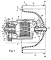
- FIG. 1 shows a first embodiment of the electric motor-fan combination according to the invention in longitudinal section
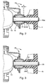
- Figure 2 shows a development of the embodiment of Figure 1
- Figure 3 shows a third embodiment
- Figure 4 shows a fourth embodiment of an electric motor-fan combination according to the invention.
- the first exemplary embodiment of an electric motor-fan-wheel combination 2 according to FIG. 1 consists of an electric motor 3 and a fan wheel 4 that can be driven by it.
- the electric motor 3 has a housing 5, which consists of a tubular return body 6 and attached thereto, substantially pot-like housing parts 7 and 8, at least one arranged in the return body 6 permanent magnet 9, an armature 10 with associated collector 11, at least one carbon brush 12 and carbon brush guide means 13, an armature shaft 14 and the armature shaft 14 receiving sliding bearings 15, 16.
- the plain bearing bushes in a conventional manner dome-shaped zones 19 on the tiltable receptacle in the housing parts 7 and 8.
- the housing parts 7 and 8 funnel-like formations 19, against which the plain bearing bushings 17 are pressed by spring tongues 20, the assume tensioning glasses 21.
- an element 22 is inserted, which surrounds the armature shaft 14 in the manner of an annular disc and is shaped like a dish in the region of its outer edge to serve as a slinger, for such oil, if necessary crawls out of the plain bearing bushing 17 along the armature shaft and is to be kept away from the collector 11.
- An identical element 22 is also inserted between the armature 10 and the plain bearing bushing 17 of the sliding bearing 15.
- the element 22 serves as a with a front-side bearing surface 18 of the plain bearing bush 17 cooperating annular thrust washer.
- this element 22 is made of a rubber-like elastic material, for example a thermoplastic elastomer.
- the armature shaft 14 has an armature shaft end 23, which protrudes through the plain bearing bushing 17 from the housing part 7, for supporting and driving the fan wheel 4.
- the fan 4 has an armature shaft end 23 comprehensive hub 24, which is pressed onto the armature shaft end 23 in the first embodiment is.
- the hub 24 is sufficiently secured relative to the armature shaft end 23 in both the axial and circumferential directions.
- the hub 24 has an axial stop surface 25 toward the adjacent bearing surface 18 of the plain bearing bushing 17.
- the element 22 serving as a thrust washer is indirectly supported in the axial direction relative to the armature 18 in any manner, for example related to the prior art.
- the element 22 is shown abutting against a bearing surface 18 of the slide bearing bushing 17 located in the housing part 7, whereas between the other bearing surface 18 belonging to this plain bearing bush 17 and the axial stop surface 25 of the hub 24, an axial distance A is shown is.
- This axial distance A is adjustable by axial alignment of the hub 24 relative to the indirectly supported on the armature 10 element 22.
- This axial clearance A is shown exaggerated in Figure 1 and is set in practice, for example, to 0.1 mm.
- a distance B is provided between the plain bearing bush 17 in the housing part 8 and the element 22 accommodated there.
- This distance ⁇ B is intentionally greater than the described distance A.
- the armature shaft in the desired manner within the bearing bushing 17 carried by the housing part 8 is freely longitudinally displaceable, whereas the displaceability of Anchor shaft 14 is limited relative to the held in the housing part 7 plain bearing bush 17 on the measure of the axial distance A.
- the supported by the housing part 7 slide bearing 15 is both a radial sliding bearing and acting in two directions thrust bearing and thus according to the German usage a so-called fixed bearing
- the other plain bearing 16 as already indicated by the not limited in itself displaceability of the armature shaft 14, a so-called floating bearing.
- the first embodiment example essentially bowl-shaped wheel disc 26 which carries on its periphery fan blades 27. These are shown in simplified form and are fixed at an axial distance from the wheel disc 26 relative to each other by means of a ring 28.
- the hub 24, the wheel disc 26, the fan blades 27 and the ring 28 are injected in the example as an integral component made of a thermoplastic material.
- the fan 4 according to US Patent 3,264,506 can be mounted on the armature shaft end 23.
- the second embodiment of an electric motor-fan combination 2a according to the figure 2 differs from the embodiment of Figure 1 in that between the hub 24 of the fan 4 and the adjacent plain bearing bush 17 of the sliding bearing 15, a buffer ring 30 is inserted.
- This buffer ring 30 is, for example, like the element 22 of a rubbery elastic material manufactured as thermoplastic elastomer and acts, as the name expresses, as a buffer element on the one hand and on the other hand, but also as a ring-like thrust washer so that the sliding bearing 15 as in the example of Figure 1 also acts as a thrust bearing.
- an axial clearance A of this slide bearing 15 is shown exaggerated between the plain bearing bushing 17 and the buffer ring 30.
- the third embodiment of an electric motor-fan combination 2b according to the figure 3 differs from the first embodiment shown in Figure 1, characterized in that a hub 24 b of a fan 4b is configured to receive at least one clamping screw 31.
- this clamping screw 31 has a per se known hexagon socket 32, is headless and therefore has the form of a so-called threaded pin.
- Such a clamping screw 31 can be arranged as an additional fastening means to the above-described press fit of the hub 24 on the armature shaft end 23 of the embodiment described above.
- a less tight interference fit or a transition fit are provided to a sliding seat. This facilitates the adjustment of the hub 24 b relative to the armature 10.
- the fourth embodiment of an electric motor-fan combination 2c according to the figure 4 differs from the third embodiment according to the figure 3, characterized in that a hub 24c of a fan 4c has an anchor shaft end 23 inclined groove 33 into which a wedge 34 is driven. This can be dispensed with a tight interference fit of the first embodiment. For example, for the alignment of the hub 24c on the armature shaft end 23, a push fit can be provided and a displacement resistance that is advantageous for adjusting axial play A can be generated by means of the wedge 34 by sliding in the groove 33.
Abstract
Description
Die Erfindung geht aus von einer Elektromotor-Lüfterrad-Kombination nach der Gattung des Patentanspruchs 1.The invention relates to an electric motor-fan combination according to the preamble of claim 1.
Die US-Patentschrift 3.264.506 offenbart eine Elektromotor-Lüfterrad-Kombination mit einem Gehäuse, mit einem Anker und einem Kollektor im Gehäuse, mit zwei Gleitlagern im Gehäuse, mit einer mittels den Gleitlagern gelagerten und den Anker und den Kollektor tragenden Ankerwelle, die ein aus dem Gehäuse herausragendes Ankerwellenende aufweist, und mit einem Lüfterrad, das eine Nabe aufweist, die auf dem Ankerwellenende befestigt ist. Dabei weisen beide Gleitlager kippbeweglich angeordnete Gleitlagerbuchsen mit stirnseitigen Lagerflächen auf, so daß die Gleitlagerbuchsen zusammen mit der Ankerwelle zwei Radiallager und daß zu dem Anker und dem Kollektor gerichtete stirnseitige Lagerflächen der beiden Gleitlagerbuchsen zusammen mit zwischen diese und dem Anker und dem Kollektor eingebauten und die Ankerwelle umgebenden Ringscheiben zusätzlich zwei Axiallager bilden. Diese Axiallager begrenzen die Verschiebbarkeit der Ankerwelle in axialer Richtung. Damit das Axialspiel auf eine Größe von beispielsweise im wesentlichen 0,125 mm einstellbar ist, besteht das Gehäuse des Elektromotors aus zwei im wesentlichen topfartigen Gehäuseteilen, von denen das eine teleskopartig in das andere einschiebbar ist zum Verringern des ursprünglich zu großen Ankerlängsspieles auf den gewünschten Wert, der weniger Geräuscherzeugurig im Betrieb des Elektromotors erwarten läßt. Nach dem Einstellen des Axialspiels auf den gewollten Wert werden an den beiden Gehäuseteilen Schweißnähte angebracht, so daß die gegenseitige Ausrichtung der Gehäuseteile und damit das eingestellte Axialspiel erhalten bleiben. In diesem Zustand hat die Nabe des Lüfterrades einen axialen Abstand von einer benachbarten Lagerbuchse. Die Ringscheiben sind beispielsweise aus Stahlblech hergestellt und am Umfang tellerrandartig ausgebildet, so daß sie zusätzlich zur Bereitstellung von Axiallagergleitflächen auch als Schleuderringe für Öl dienen, mit dem die porös ausgebildeten Gleitlagerschalen getränkt sind.The US Patent 3,264,506 discloses an electric motor-fan combination with a housing, with an armature and a collector in the housing, with two plain bearings in the housing, with a mounted on the bearings and the armature and the collector-bearing armature shaft, a having armature shaft end protruding from the housing and having a fan wheel having a hub fixed on the armature shaft end. Both slide bearings tiltably arranged plain bearing bushes with frontal bearing surfaces, so that the plain bearing bushes together with the armature shaft two radial bearings and that directed to the armature and the collector frontal bearing surfaces of the two plain bearing bushes together with between this and the armature and the collector and the armature shaft surrounding annular discs additionally form two thrust bearings. These thrust bearings limit the displaceability of the armature shaft in the axial direction. So that the axial play on a size of, for example, substantially 0.125 mm is adjustable, the housing of the electric motor consists of two substantially pot-like housing parts, one of which is telescopically inserted into the other to reduce the originally too large anchor longitudinal play to the desired value, the less noisy in operation to expect the electric motor. After adjusting the axial clearance to the desired value welds are attached to the two housing parts, so that the mutual alignment of the housing parts and thus the set axial play are maintained. In this state, the hub of the fan wheel has an axial distance from an adjacent bearing bush. The annular discs are for example made of sheet steel and formed on the periphery plate edge-like, so that they serve in addition to the provision of Axiallagergleitflächen as sling rings for oil, with which the porous trained plain bearing shells are impregnated.
Die US-Patentschrift 3.624.434 offenbart einen Elektromotor, der beispielsweise zur Kombination mit dem Lüfterrad gemäß der bereits genannten US-Patentschrift 3.264.506 vorgesehen ist. Dieser Elektromotor hat ein Gehäuse, einen Anker, einen Kollektor und zwei Gleitlager im Gehäuse, eine mittels den Gleitlagern gelagerte und den Anker sowie den Kollektor tragende Ankerwelle, die ein aus dem Gehäuse herausragendes Ankerwellenende aufweist, auf dem eine Nabe eines Lüfterrades befestigt wird, wobei beide Gleitlager die Ankerwelle aufnehmende Gleitlagerbuchsen mit stirnseitigen Lagerflächen aufweisen und beide stirnseitigen Lagerflächen einer der Gleitlagerbuchsen zusammen mit einer zwischen dem Kollektor und dieser Gleitlagerbuchse um die Ankerwelle angeordneten Ringscheibe und mit einem jenseits der Ringscheibe auf einem durch die Gleitlagerbuchse hindurchgesteckten, freien Ende der Ankerwelle aufgepreßten axialen Anschlagring ein in zwei Richtungen wirkendes Axiallager für die Ankerwelle bildet. Hierdurch ist das aus der Ringscheibe und dem axialen Anschlagring und der dazwischen befindlichen Gleitbuchse gebildete Gleitlager gemäß dem deutschen Sprachgebrauch ein sogenanntes Festlager, wogegen das andere Gleitlager, an das das für das Lüfterrad bestimmte Ankerwellenende sich anschließt, nach deutschem Sprachgebrauch ein sogenanntes Loslager ist. Damit ist gemeint, daß dieses Loslager lediglich radiale Lagerkräfte erzeugt und einer Verschiebung der Ankerwelle keinen Widerstand entgegensetzt, also in axialer Richtung die Ankerwelle lose aufnimmt. Die Ringscheibe als Bestandteil des Axiallagers ist aus Blech geformt und hat einen Rand ähnlich einem Teller, so daß die Ringscheibe zusätzlich zum Bereitstellen einer axialen Lagerfläche auch als Ölschleuderring dient zur Vermeidung des Wanderns von Öl aus der porös ausgebildeten Gleitlagerbuchse hin zu dem Kollektor.US Pat. No. 3,624,434 discloses an electric motor provided for example for combination with the fan wheel according to the already mentioned US Pat. No. 3,264,506. This electric motor has a housing, an armature, a collector and two plain bearings in the housing, mounted by means of the plain bearings and the armature and the collector-bearing armature shaft having an outstanding from the housing armature shaft end on which a hub of a fan wheel is attached, wherein both plain bearings have the armature shaft receiving plain bearing bushes with end bearing surfaces and both end bearing surfaces of the plain bearing bushes together with a between the collector and this plain bearing bush to the armature shaft arranged annular disc and formed with a beyond the annular disc on a through the plain bearing bush inserted, free end of the armature shaft pressed axial stop ring acting in two directions thrust bearing for the armature shaft. As a result, the sliding bearing formed from the annular disc and the axial stop ring and the sliding bush located therebetween according to German usage is a so-called fixed bearing, whereas the other plain bearing to which the armature shaft end for the fan is connected, according to German usage is a so-called floating bearing. This means that this floating bearing generates only radial bearing forces and a resistance to displacement of the armature shaft opposes, so loosely receives the armature shaft in the axial direction. The annular disc as part of the thrust bearing is formed of sheet metal and has an edge similar to a plate, so that the annular disc in addition to providing an axial bearing surface as an oil slinger serves to prevent the migration of oil from the porous trained plain bearing bush towards the collector.
Die erfindungsgemäße Elektromotor-Lüfterrad-Kombination mit den kennzeichnenden Merkmalen des Anspruches 1 ist preisgünstig, weil eine ohnehin notwendige Nabe des Lüftrades die Aufgabe des axialen Anschlagringes gemäß dem Stand der Technik für die Bildung eines Axiallagers einspart. Deshalb wird ein im Gehäuse des Elektromotors des Standes der Technik für den axialen Anschlagring vorgesehener Einbauraum eingespart.The electric motor-fan combination according to the invention with the characterizing features of claim 1 is inexpensive because an already necessary hub of the Lüftrades saves the task of the axial stop ring according to the prior art for the formation of a thrust bearing. Therefore, a housing provided in the housing of the electric motor of the prior art for the axial stop ring installation space is saved.
Durch die in den weiteren Ansprüchen aufgeführten Maßnahmen sind vorteilhafte Ausgestaltungen der im Patentanspruch 1 angegebenen Elektromotor-Lüfterrad-Kombination möglich.The measures listed in the other claims advantageous embodiments of the specified in claim 1 electric motor-fan combination are possible.
Das kennzeichnende Merkmal des Anspruches 2 ergibt den Vorteil einer elastischen und dadurch geräuschmindernden Begrenzung der Verschiebbarkeit der Ankerwelle relativ zu dem Gehäuse des Elektromotors. Demgemäß ist hartes Anschlagen der Nabe des Lüfterrades an der Gleitlagerbuchse und dadurch das Abstrahlen von störendem Klack-Geräusch durch das Gehäuse des Elektromotors oder das Lüfterrad vermieden.The characterizing feature of
Das kennzeichnende Merkmal des Anspruches 3 gibt ein preisgünstig herstellbares Ausführungsbeispiel an.The characterizing feature of
Die kennzeichnenden Merkmale der Ansprüche 4 und 5 sind alternativ anwendbar und bieten den Vorteil einer erleichterten Montage der Nabe des Lüfterrades auf dem Ankerwellenende dadurch, daß eine dem Anspruch 3 gemäße Preßpassung weniger stramm ausbildbar ist. Für die Ausbildungsbeispiele der Ansprüche 4 und 5 genügt eine Schiebesitzpassung zur Anordnung der jeweiligen Nabe auf dem Ankerwellenende.The characterizing features of
Das Verfahren mit den kennzeichnenden Merkmalen des Anspruches 6 ergibt den Vorteil, daß zum Einstellen des Axialspiels keine Fühlerlehre zwischen die Gleitlagerbuchse und die Nabe des Lüfterrades einzuführen ist. Dadurch kann, von der Nabe ausgehend ein eine Anzahl Lüfterschaufeln tragender Tragkörper schalenartig und dabei den Elektromotor auf einem Teil seiner Länge,umgebend ausgebildet werden.The method with the characterizing features of
Das Verfahren mit den kennzeichnenden Merkmalen des Anspruches 7 wird angewandt zur Herstellung der Elektromotor-Lüfterrad-Kombination gemäß dem Anspruch 3.The method with the characterizing features of
Vier Ausführungsbeispiele der erfindungsgemäßen Elektromotor-Lüfter-Kombination sind in der Zeichnung dargestellt und in der nachfolgenden Beschreibung näher erläutert. Es zeigen Figur 1 ein erstes Ausführungsbeispiel der erfindungsgemäßen Elektromotor-Lüfterrad-Kombination im Längsschnitt, Figur 2 eine Weiterbildung des Ausführungsbeispiels der Figur 1, Figur 3 ein drittes Ausführungsbeispiel und Figur 4 ein viertes Ausführungsbeispiel einer erfindungsgemäßen Elektromotor-Lüfterrad-Kombination.Four embodiments of the electric motor-fan combination according to the invention are shown in the drawing and explained in more detail in the following description. 1 shows a first embodiment of the electric motor-fan combination according to the invention in longitudinal section, Figure 2 shows a development of the embodiment of Figure 1, Figure 3 shows a third embodiment and Figure 4 shows a fourth embodiment of an electric motor-fan combination according to the invention.
Das erste Ausführungsbeispiel einer Elektromotor-Lüfterrad-Kombination 2 gemäß der Figur 1 besteht aus einem Elektromotor 3 und einem von diesem antreibbaren Lüfterrad 4.The first exemplary embodiment of an electric motor-fan-
Der Elektromotor 3 besitzt ein Gehäuse 5, das aus einem rohrartigen Rückschlußkörper 6 und daran angesetzten, im wesentlichen topfartigen Gehäuseteilen 7 und 8 besteht, wenigstens einen in dem Rückschlußkörper 6 angeordneten Permanentmagnet 9, einen Anker 10 mit zugeordnetem Kollektor 11, wenigstens eine Kohlebürste 12 und Kohlebürstenführungsmittel 13, eine Ankerwelle 14 und zwei die Ankerwelle 14 aufnehmende Gleitlager 15, 16. Im Ausführungsbeispiel weisen die Gleitlager 16 Gleitlagerbuchsen 17 auf, die stirnseitig Lagerflächen 18 aufweisen, die vorzugsweise eben ausgebildet sind und dadurch kreisringartig verlaufen. Außen weisen die Gleitlagerbuchsen in an sich bekannter Weise kalottenartig geformte Zonen 19 auf zur kippbeweglichen Aufnahme in den Gehäuseteilen 7 und 8. Zu diesem Zweck weisen die Gehäuseteile 7 und 8 trichterähnliche Ausformungen 19 auf, gegen die die Gleitlagerbuchsen 17 angedrückt sind mittels Federzungen 20, die von Spannbrillen 21 ausgehen.The
Zwischen dem Kollektor 11 und dem Gleitlager 16 bzw. deren Gleitlagerbuchse 17 ist ein Element 22 eingefügt, das nach Art einer Ringscheibe die Ankerwelle 14 umgibt und im Bereich seines äußeren Randes tellerartig geformt ist, um als Ölschleuderring zu dienen, für solches Öl, das gegebenenfalls aus der Gleitlagerbuchse 17 heraus entlang der Ankerwelle kriecht und vom Kollektor 11 fernzuhalten ist. Ein baugleiches Element 22 ist auch eingefügt zwischen den Anker 10 und die Gleitlagerbuchse 17 des Gleitlagers 15. Hier dient das Element 22 als eine mit einer stirnseitigen Lagerfläche 18 der Gleitlagerbuchse 17 zusammen arbeitende ringförmige Anlaufscheibe. Beispielsweise ist dieses Element 22 aus einem gummiartig elastischen Werkstoff, beispielsweise einem thermoplastischen Elastomer, hergestellt. Dadurch vermeidet das Element 22 das Entstehen von metallischen Aufschlaggeräuschen anläßlich unvermeidlicher Relativbewegungen des Ankers 10 in Richtung der im Gehäuseteil 7 gehaltenen Gleitlagerbuchse 17.Between the
Die Ankerwelle 14 hat ein Ankerwellenende 23, das durch die Gleitlagerbuchse 17 hindurch aus dem Gehäuseteil 7 herausragt, zum Tragen und Antreiben des Lüfterrades 4. Hierfür besitzt das Lüfterrad 4 eine das Ankerwellenende 23 umfassende Nabe 24, die im ersten Ausführungsbeispiel auf das Ankerwellenende 23 aufgepreßt ist. Dadurch ist die Nabe 24 relativ zum Ankerwellenende 23 sowohl in axialer als auch in Umfangsrichtung ausreichend befestigt. Zur benachbarten Lagerfläche 18 der Gleitlagerbuchse 17 hin hat die Nabe 24 eine axiale Anschlagfläche 25. Das hier als Anlaufscheibe dienende Element 22 ist in irgendeiner, beispielsweise zum Stand der Technik gehörenden Weise mittelbar in axialer Richtung relativ zum Anker 18 abgestützt. In der Figur 1 ist das Element 22 an einer Lagerfläche 18 der in dem Gehäuseteil 7 befindlichen Gleitlagerbuchse 17 anliegend dargestellt, wogegen zwischen der anderen Lagerfläche 18, die zu dieser Gleitlagerbuchse 17 gehört, und der axialen Anschlagfläche 25 der Nabe 24 ein axialer Abstand A dargestellt ist. Dieser axiale Abstand A ist einstellbar durch axiale Ausrichtung der Nabe 24 relativ zu dem mittelbar am Anker 10 abgestützten Element 22. Dieses axiale Spiel A ist in der Figur 1 übertrieben groß dargestellt und wird in der Praxis beispielsweise auf 0,1 mm eingestellt.The
Zwischen der Gleitlagerbuchse 17 im Gehäuseteil 8 und dem dort untergebrachten Element 22 ist ein Abstand B vorgesehen. Dieser Abstand·B ist gewollt größer als der beschriebene Abstand A. Dies hat zur Folge, daß die Ankerwelle in gewollter Weise innerhalb der vom Gehäuseteil 8 getragenen Gleitlagerbuchse 17 unbehindert längsverschieblich ist, wogegen die Verschieblichkeit der Ankerwelle 14 relativ zu der im Gehäuseteil 7 gehaltenen Gleitlagerbuchse 17 begrenzt ist auf das Maß des axialen Abstandes A. Dadurch ist das vom Gehäuseteil 7 getragene Gleitlager 15 sowohl ein Radialgleitlager als auch ein in zwei Richtungen wirkendes Axiallager und somit gemäß dem deutschen Sprachgebrauch ein sogenanntes Festlager. Im Unterschied dazu ist das andere Gleitlager 16, so wie dies bereits durch die an sich nicht begrenzte Verschieblichkeit der Ankerwelle 14 angedeutet ist, ein sogenanntes Loslager.Between the
An die Nabe 24 des Lüfterrades 4 schließt sich eine im ersten Ausführungsbeispiel Beispiel im wesentlichen schüsselartig ausgebildete Radscheibe 26 an, die an ihrem Umfang Lüfterradschaufeln 27 trägt. Diese sind vereinfacht dargestellt und werden in axialem Abstand von der Radscheibe 26 relativ zueinander fixiert mittels eines Ringes 28. Die Nabe 24, die Radscheibe 26, die Lüfterradschaufeln 27 und der Ring 28 sind im Beispiel als integrales Bauteil aus einem thermoplastischen Werkstoff gespritzt. Jedoch steht es einem Konstrukteur frei, das Lüfterrad 4 zumindest teilweise aus einem metallischen Werkstoff herzustellen. Beispielsweise kann auch das Lüfterrad 4 gemäß der US-Patentschrift 3,264,506 auf dem Ankerwellenende 23 befestigt werden.To the
Wenn, wie im dargestellten Beispiel gemäß der Figur 1, die schüsselartig ausgebildete Radscheibe 26 den Zugang zu dem mit A bezeichneten Axialspiel zwischen der Gleitlagerbuchse 17 und der axialen Anschlagfläche 25 der Nabe 24 erschwert oder verhindert, wird das Axialspiel A gemäß dem folgend beschriebenen Verfahren eingestellt:
- Eine beim
Gehäuseteil 8befindliche Stirnseite 29 derAnkerwelle 14 wird nach dem Zusammenbau desElektromotors 3 in einer nicht dargestellten Weise abgestützt. Dann wird gegen die nicht dargestellte Abstützung die Nabe 24 in Ausrichtung zumAnkerwellenende 23 gebracht und entlang diesem auf dieAnkerwelle 14 aufgepreßt unter Belassung eines axialen Abstandes zwischen der axialen - Anschlagfläche 25 und der
zugeordneten Gleitlagerbuchse 17, wobei dieser axiale Abstand mit Sicherheit größer als der einzustellende axiale Abstand A ist. Dann wird beispielsweise dasGehäuse 5 desElektromotors 3 relativ zu derAnkerwelle 14 verschoben und dabei die Größe des Verschiebeweges gemessen, beispielsweise unter Berücksichtigung einer dabei stattfindenden elastischen Zusammendrückung desElementes 22, das demGleitlager 15 zugeordnet ist. Von dem dabei ermittelten Verschiebemaß wird ein Wert in der Größe des gewollten Axialspieles A abgezogen, wonach das erhaltene Ergebnis ein Verschiebemaß angibt für eine weitere Verschiebung der Nabe 24 relativ zu demAnker 10 mittels einer Presse. Dieses Verfahren ist beispielsweise von Hand oder maschinell durchführbar. Im letzteren Fall braucht man eine Steuerung für die Presse, die ihre Vorgaben aus einer automatischen Verschiebewegmeßeinrichtung erhält.
- An end face 29 of the
armature shaft 14 located on thehousing part 8 is supported after assembly of theelectric motor 3 in a manner not shown. Then, against the support not shown, thehub 24 is brought into alignment with thearmature shaft end 23 and pressed along this on thearmature shaft 14, leaving an axial distance between the axial - Stop surface 25 and the associated
plain bearing bushing 17, wherein this axial distance is certainly greater than the axial distance A to be set. Then, for example, thehousing 5 of theelectric motor 3 is displaced relative to thearmature shaft 14 and thereby measured the size of the displacement, for example, taking into account a taking place thereby elastic compression of theelement 22, which is associated with the slidingbearing 15. From the thus determined displacement measure a value in the size of the desired axial clearance A is subtracted, after which the result obtained indicates a shift measure for a further displacement of thehub 24 relative to thearmature 10 by means of a press. This method can be performed, for example, by hand or by machine. In the latter case, one needs a control for the press, which receives its specifications from an automatic Verschiewewegmeßeinrichtung.
Das zweite Ausführungsbeispiel einer Elektromotor-Lüfterrad-Kombination 2a gemäß der Figur 2 unterscheidet sich vom Ausführungsbeispiel gemäß der Figur 1 dadurch, daß zwischen die Nabe 24 des Lüfterrades 4 und die benachbarte Gleitlagerbuchse 17 des Gleitlagers 15 ein Pufferring 30 eingefügt ist. Dieser Pufferring 30 ist beispielsweise wie das Element 22 aus einem gummiartig elastischen Werkstoff wie thermoplastischem Elastomer hergestellt und wirkt, wie dies der Name ausdrückt, als Pufferelement einerseits und andererseits aber auch als eine ringartige Anlaufscheibe, damit das Gleitlager 15 wie im Beispiel der Figur 1 auch als ein Axiallager wirkt. Wiederum ist ein Axialspiel A dieses Gleitlagers 15 übertrieben groß dargestellt zwischen der Gleitlagerbuchse 17 und dem Pufferring 30. Das Axialspiel A ist deshalb an dieser Stelle eingezeichnet, weil durch die im beschriebenen Verfahren genannte Relativverschiebung des Gehäuses 5 relativ zur Ankerwelle 14 und damit dem Anker 10 dann, wenn der Pufferring 30 mit radialer Spannung das Ankerwellenende 23 A umschließt, dazu neigt, an der Nabe 24 zu verbleiben. Erkennbar ist, daß durch Anordnung des Pufferringes 30 direkter mechanischer Kontakt zwischen der normalerweise aus Metall gefertigten Gleitlagerbuchse 17 und der aus relativ hartem Kunststoff oder Metall hergestellten Nabe 24 des Lüfterrades 4 vermieden wird. Die Verhinderung eines harten mechanischen Kontaktes mittels des Pufferringes 30 ist also eine geräuschmindernde Maßnahme.The second embodiment of an electric motor-
Das dritte Ausführungsbeispiel einer Elektromotor-Lüfterrad-Kombination 2b gemäß der Figur 3 unterscheidet sich vom ersten Ausführungsbeispiel gemäß der Figur 1 dadurch, daß eine Nabe 24 b eines Lüfterrades 4b ausgestaltet ist zur Aufnahme wenigstens einer Klemmschraube 31. Beispielsweise hat diese Klemmschraube 31 einen an sich bekannten Innensechskant 32, ist kopflos und hat deshalb die Form eines sogenannten Gewindestiftes. Eine solche Klemmschraube 31 kann als ein zusätzliches Befestigungsmittel zu dem voranstehend beschriebenen Preßsitz der Nabe 24 auf dem Ankerwellenende 23 des voranstehend beschriebenen Ausführungsbeispiels angeordnet werden. Andererseits kann aber auch Dank der Anordnung der wenigstens einen Klemmschraube 31 ein weniger strammer Preßsitz oder aber eine Übergangspassung bis hin zu einem Schiebesitz vorgesehen werden. Dies erleichtert das Einstellen der Nabe 24b relativ zum Anker 10.The third embodiment of an electric motor-
Das vierte Ausführungsbeispiel einer Elektromotor-Lüfterrad-Kombination 2c gemäß der Figur 4 unterscheidet sich vom dritten Ausführungsbeispiel gemäß der Figur 3 dadurch, daß eine Nabe 24c eines Lüfterrades 4c eine zum Ankerwellenende 23 geneigte Nut 33 aufweist, in die ein Keil 34 eintreibbar ist. Dadurch kann auf eine stramme Preßpassung des ersten Ausführungsbeispiels verzichtet werden. Beispielsweise kann für das Ausrichten der Nabe 24c auf dem Ankerwellenende 23 eine Schiebepassung vorgesehen werden und ein für das Einstellen von Axialspiel A vorteilhafter Verschiebewiderstand kann mittels des Keils 34 durch Verschieben in der Nut 33 erzeugt werden.The fourth embodiment of an electric motor-
Aus der Beschreibung der Unterschiede bezüglich der Befestigungen der unterschiedlichen Naben 24, 24b und 24c auf dem jeweiligen Ankerwellenende 23 geht hervor, daß der Gedanke, unter Zuhilfenahme einer axialen Anschlagfläche, die sich an einer Nabe eines Lüfterrades befindet, ein Axiallager mit einstellbarem Axialspiel A zu schaffen unabhängig davon ist, in welcher Weise letztlich die betreffende Nabe betriebssicher auf dem zugeordneten Ankerwellenende befestigt wird. Beispielsweise könnte man, wenn eine solche Nabe aus Stahl besteht, eine Sicherung per Schweißnahtanordnung vornehmen.From the description of the differences in the attachments of the
Das voranstehend beschriebene Verwenden einer Nabe eines Lüfterrades als ein Bestandteil eines Axiallagers, das eine Gleitlagerbuchse 17 mit stirnseitigen Lagerflächen 18 aufweist, ist nicht gebunden an die in der Figur 1 dargestellte Anordnung eines Kollektors 11. Vielmehr kann ein Axiallager der beschriebenen Art auch verwendet werden bei einem andersartig gestaltetem Elektromotor einer Elektromotor-Lüfterrad-Kombination.The above-described use of a hub of a fan as a component of a thrust bearing, which has a
Claims (7)
- Electric motor/fan impeller combination (2) having a housing (5), having an armature (10) in the housing, having two plain bearings (15, 16) in the housing, having an armature shaft (14) which is mounted by means of the plain bearings and supports the armature and has an armature-shaft end (23) which protrudes from the housing, and having a fan impeller (4) which has a hub (24) which is secured on the armature-shaft end, with the two plain bearings (15, 16) having plain bearing bushes (17) which hold the armature shaft (14) and have end-face bearing areas (18), and the two end-face bearing areas of one of the plain bearing bushes together with an annular disc-like element (22), which is arranged around the armature shaft between the armature (10) and this plain bearing bush, and an axial stop, which is oriented towards the opposite end-face bearing area of this plain bearing bush (17) and is secured on the armature shaft, forming an axial bearing which acts in two directions, characterized in that the hub (24, 24b, 24c) of the fan impeller (4, 4b, 4c) forms the axial stop (25) of the axial bearing (15; 17, 22, 23, 24).
- Electric motor/fan impeller combination according to Claim 1, characterized in that a buffer ring (30) which surrounds the armature-shaft end (23) and is composed of a rubbery elastic material is fitted between the hub (24) of the fan impeller (4) and an end-face bearing area (18) of the plain bearing bush (17) of the plain bearing (15).
- Electric motor/fan impeller combination according to Claim 1 or 2, characterized in that the hub (24) of the fan impeller (4) is pressed onto the armature-shaft end (23, 23a).
- Electric motor/fan impeller combination according to Claim 1 or 2, characterized in that the hub (24b) of the fan impeller (4b) is fixed on the armature-shaft end (23) by means of at least one clamping screw (31).
- Electric motor/fan impeller combination according to Claim 1 or 2, characterized in that the hub (24c) of the fan impeller (4c) is fixed on the armature-shaft end (23) by means of a wedge (34).
- Method for producing an electric motor/fan impeller combination (2) having a housing (5), having an armature (10) in the housing, having two plain bearings (15, 16) in the housing, having an armature shaft (14) which is mounted by means of the plain bearings and supports the armature and has an armature-shaft end (23) which protrudes from the housing, and having a fan impeller (4) which has a hub (24) which is secured on the armature-shaft end, with the two plain bearings (15, 16) having plain bearing bushes (17) which hold the armature shaft and have end-face bearing areas, and the two end-face bearing areas (18) of one of the two plain bearing bushes together with an annular disc-like element (22), which is arranged around the armature shaft between the armature and this plain bearing bush, with an axial stop, which is oriented towards the opposite end-face bearing area (18) of this plain bearing bush, forming an axial bearing which acts in two directions, with the hub (24) of the fan impeller (4) forming an axial stop with an end which is directed towards one bearing area of the plain bearing bush, characterized in that, after the electric motor (3) is assembled, the hub (24, 24b, 24c) of the fan impeller (4, 4b, 4c) is pushed onto the armature-shaft end (23, 23a) while leaving a space for the closest bearing area (18) of the closest plain bearing bush (17), in that the armature shaft (14) is moved at least once, in that the movement distance is measured, in that a value of the magnitude (A) of the desired axial play (A) is subtracted from the measured value of the movement distance, and in that a movement device is controlled on the basis of a calculated value of this type in order to move the hub (24, 24b, 24c) on the armature-shaft end (23, 23a) in the direction of the armature (10) by a movement distance which is associated with the calculated value.
- Method according to Claim 6, characterized in that the movement device used is a controllable press which is pressed against the end face of the hub (24, 24b, 25c) such that it acts in the direction of the armature (10), while the end face of the armature shaft (14) is supported.
Applications Claiming Priority (3)
| Application Number | Priority Date | Filing Date | Title |
|---|---|---|---|
| DE19846919 | 1998-10-12 | ||
| DE19846919A DE19846919A1 (en) | 1998-10-12 | 1998-10-12 | Electric motor and fan wheel assembly has hub of fan fixed to motor shaft carried in two bearing bushes and axial movement is limited by hub and adjacent bush |
| PCT/DE1999/002349 WO2000022717A1 (en) | 1998-10-12 | 1999-07-30 | Electric motor fan wheel combination and method for the production thereof |
Publications (2)
| Publication Number | Publication Date |
|---|---|
| EP1046215A1 EP1046215A1 (en) | 2000-10-25 |
| EP1046215B1 true EP1046215B1 (en) | 2006-12-13 |
Family
ID=7884162
Family Applications (1)
| Application Number | Title | Priority Date | Filing Date |
|---|---|---|---|
| EP99950472A Expired - Lifetime EP1046215B1 (en) | 1998-10-12 | 1999-07-30 | Electric motor fan wheel combination and method for the production thereof |
Country Status (8)
| Country | Link |
|---|---|
| US (1) | US6382936B1 (en) |
| EP (1) | EP1046215B1 (en) |
| JP (1) | JP2002528031A (en) |
| KR (1) | KR100634033B1 (en) |
| BR (1) | BR9906865A (en) |
| DE (2) | DE19846919A1 (en) |
| ES (1) | ES2278458T3 (en) |
| WO (1) | WO2000022717A1 (en) |
Families Citing this family (11)
| Publication number | Priority date | Publication date | Assignee | Title |
|---|---|---|---|---|
| JP2002137620A (en) * | 2000-11-01 | 2002-05-14 | Asmo Co Ltd | Air conditioning motor for vehicle and air conditioner for vehicle |
| US6890159B2 (en) * | 2002-03-19 | 2005-05-10 | Denso Corporation | Air blower with fan unable to contact motor housing |
| US6995487B2 (en) * | 2003-07-25 | 2006-02-07 | Siemens Vdo Automotive Inc. | Endplay adjustment and bearing decoupling in an electric motor |
| US20060058788A1 (en) * | 2004-08-27 | 2006-03-16 | Hammer Michael A | Multi-axial connection system |
| DE102005030871A1 (en) * | 2005-07-01 | 2007-01-11 | Robert Bosch Gmbh | Bearing device, method for mounting a bearing device and electric machine with a bearing device |
| JP5574628B2 (en) * | 2009-02-17 | 2014-08-20 | 山洋電気株式会社 | Centrifugal fan |
| DE102010062691A1 (en) * | 2010-12-09 | 2012-06-14 | Robert Bosch Gmbh | Method for adjusting the axial clearance between a motor armature and a bearing and a bearing of an armature shaft |
| JP2012215099A (en) * | 2011-03-31 | 2012-11-08 | Minebea Motor Manufacturing Corp | Impeller and centrifugal fan |
| KR101216588B1 (en) | 2011-09-22 | 2012-12-31 | 동양팬 주식회사 | Out rotor type fan motor |
| US9995305B2 (en) | 2013-10-08 | 2018-06-12 | Regal Beloit America, Inc. | Fluid flow apparatus, fan assembly and associated method |
| KR101912428B1 (en) * | 2016-07-29 | 2018-10-26 | 산일테크(주) | Fan motor |
Family Cites Families (8)
| Publication number | Priority date | Publication date | Assignee | Title |
|---|---|---|---|---|
| FR1129253A (en) * | 1955-07-27 | 1957-01-17 | Improvements to fans for automobile engines and the like | |
| US3240517A (en) * | 1963-03-12 | 1966-03-15 | Torrington Mfg Co | Fan hub |
| US3624434A (en) * | 1970-11-20 | 1971-11-30 | Gen Motors Corp | Bearing support assembly for dynamoelectric machines and a method of manufacture therefor |
| FR2486324A1 (en) * | 1980-07-02 | 1982-01-08 | Paris & Du Rhone | Ventilation fan for automobile alternator or dynamo - has resilient washer between fan blade and hub absorbing machine vibrations |
| DE9014322U1 (en) * | 1990-10-16 | 1992-02-13 | Robert Bosch Gmbh, 7000 Stuttgart, De | |
| JP3381356B2 (en) * | 1994-02-16 | 2003-02-24 | 松下電器産業株式会社 | Motor fan |
| US5996685A (en) * | 1995-08-03 | 1999-12-07 | Valeo Thermique Moteur | Axial flow fan |
| DE19606146A1 (en) * | 1996-02-20 | 1997-08-21 | Vorwerk Co Interholding | High-speed electric motor |
-
1998
- 1998-10-12 DE DE19846919A patent/DE19846919A1/en not_active Withdrawn
-
1999
- 1999-07-30 US US09/581,342 patent/US6382936B1/en not_active Expired - Fee Related
- 1999-07-30 ES ES99950472T patent/ES2278458T3/en not_active Expired - Lifetime
- 1999-07-30 JP JP2000576527A patent/JP2002528031A/en active Pending
- 1999-07-30 WO PCT/DE1999/002349 patent/WO2000022717A1/en active IP Right Grant
- 1999-07-30 EP EP99950472A patent/EP1046215B1/en not_active Expired - Lifetime
- 1999-07-30 KR KR1020007006227A patent/KR100634033B1/en not_active IP Right Cessation
- 1999-07-30 DE DE59914057T patent/DE59914057D1/en not_active Expired - Lifetime
- 1999-07-30 BR BR9906865-6A patent/BR9906865A/en not_active IP Right Cessation
Also Published As
| Publication number | Publication date |
|---|---|
| KR100634033B1 (en) | 2006-10-17 |
| BR9906865A (en) | 2000-10-17 |
| WO2000022717A1 (en) | 2000-04-20 |
| ES2278458T3 (en) | 2007-08-01 |
| DE19846919A1 (en) | 2000-04-13 |
| KR20010024704A (en) | 2001-03-26 |
| EP1046215A1 (en) | 2000-10-25 |
| US6382936B1 (en) | 2002-05-07 |
| JP2002528031A (en) | 2002-08-27 |
| DE59914057D1 (en) | 2007-01-25 |
Similar Documents
| Publication | Publication Date | Title |
|---|---|---|
| DE69737869T2 (en) | Geared motor, in particular for driving accessories in motor vehicles | |
| DE60033457T2 (en) | Micromotor and its manufacturing process | |
| DE4340607B4 (en) | Bearing for rotatably supporting a shaft | |
| EP3431815B1 (en) | Belt tensioning device | |
| EP2000699B1 (en) | Torque oscillation attenuator or decoupler with coiled wire springs in a drive disc | |
| DE3200610A1 (en) | BELT TENSIONING DEVICE FOR A DRIVE BELT DRIVEN BY A MOTOR FOR AUXILIARY SENSORS OF MOTOR VEHICLES | |
| DE8510144U1 (en) | Belt tensioning device for the automatic tensioning of an endless drive belt | |
| EP1046215B1 (en) | Electric motor fan wheel combination and method for the production thereof | |
| DE102004041074A1 (en) | Electric machine with an axial spring element | |
| DE4404421B4 (en) | Electromagnetic coupling | |
| DE60025682T2 (en) | fan | |
| DE19839407C1 (en) | Electric drive unit | |
| EP0472828B1 (en) | Bearing for a gear shift lever | |
| DE112009002345T5 (en) | Processing video data in devices with limited resources | |
| WO2006032587A1 (en) | Electric machine | |
| DE19839640B4 (en) | Motor with a spherical bearing that can be fixed in a bearing seat with axial play adjustment for a rotor shaft and method for axial play adjustment for a rotor shaft | |
| DE19833982B4 (en) | Spherical plain bearings | |
| DE4039453C2 (en) | Vehicle windscreen wiper motor - has spring between inner ring of bearing and armature shaft securing ring to absorb axial thrust | |
| DE19818059B4 (en) | Rolling bearing assembly for small electric motors | |
| EP0572821A1 (en) | Vehicle steering column | |
| DE3832543A1 (en) | Bearing for the elastic support of a shaft, especially a centre bearing for the prop shaft of a vehicle drive | |
| WO2011160984A2 (en) | Electric machine | |
| DE102013209202A1 (en) | Drive device, in particular adjusting device in a vehicle | |
| DE10056342B4 (en) | Torsionsdämpfer for a friction clutch, in particular for motor vehicles | |
| EP1071188B1 (en) | Electric motor |
Legal Events
| Date | Code | Title | Description |
|---|---|---|---|
| PUAI | Public reference made under article 153(3) epc to a published international application that has entered the european phase |
Free format text: ORIGINAL CODE: 0009012 |
|
| AK | Designated contracting states |
Kind code of ref document: A1 Designated state(s): AT BE CH CY DE DK ES FI FR GB GR IE IT LI LU MC NL PT SE |
|
| 17P | Request for examination filed |
Effective date: 20001020 |
|
| RBV | Designated contracting states (corrected) |
Designated state(s): DE ES FR GB IT |
|
| GRAP | Despatch of communication of intention to grant a patent |
Free format text: ORIGINAL CODE: EPIDOSNIGR1 |
|
| GRAS | Grant fee paid |
Free format text: ORIGINAL CODE: EPIDOSNIGR3 |
|
| GRAA | (expected) grant |
Free format text: ORIGINAL CODE: 0009210 |
|
| AK | Designated contracting states |
Kind code of ref document: B1 Designated state(s): DE ES FR GB IT |
|
| REG | Reference to a national code |
Ref country code: GB Ref legal event code: FG4D Free format text: NOT ENGLISH |
|
| REF | Corresponds to: |
Ref document number: 59914057 Country of ref document: DE Date of ref document: 20070125 Kind code of ref document: P |
|
| GBT | Gb: translation of ep patent filed (gb section 77(6)(a)/1977) |
Effective date: 20070321 |
|
| ET | Fr: translation filed | ||
| REG | Reference to a national code |
Ref country code: ES Ref legal event code: FG2A Ref document number: 2278458 Country of ref document: ES Kind code of ref document: T3 |
|
| PLBE | No opposition filed within time limit |
Free format text: ORIGINAL CODE: 0009261 |
|
| STAA | Information on the status of an ep patent application or granted ep patent |
Free format text: STATUS: NO OPPOSITION FILED WITHIN TIME LIMIT |
|
| 26N | No opposition filed |
Effective date: 20070914 |
|
| PGFP | Annual fee paid to national office [announced via postgrant information from national office to epo] |
Ref country code: FR Payment date: 20090720 Year of fee payment: 11 Ref country code: ES Payment date: 20090724 Year of fee payment: 11 |
|
| PGFP | Annual fee paid to national office [announced via postgrant information from national office to epo] |
Ref country code: GB Payment date: 20090724 Year of fee payment: 11 |
|
| PGFP | Annual fee paid to national office [announced via postgrant information from national office to epo] |
Ref country code: IT Payment date: 20090730 Year of fee payment: 11 |
|
| GBPC | Gb: european patent ceased through non-payment of renewal fee |
Effective date: 20100730 |
|
| REG | Reference to a national code |
Ref country code: FR Ref legal event code: ST Effective date: 20110331 |
|
| PG25 | Lapsed in a contracting state [announced via postgrant information from national office to epo] |
Ref country code: IT Free format text: LAPSE BECAUSE OF NON-PAYMENT OF DUE FEES Effective date: 20100730 Ref country code: FR Free format text: LAPSE BECAUSE OF NON-PAYMENT OF DUE FEES Effective date: 20100802 |
|
| PG25 | Lapsed in a contracting state [announced via postgrant information from national office to epo] |
Ref country code: GB Free format text: LAPSE BECAUSE OF NON-PAYMENT OF DUE FEES Effective date: 20100730 |
|
| REG | Reference to a national code |
Ref country code: ES Ref legal event code: FD2A Effective date: 20110818 |
|
| PG25 | Lapsed in a contracting state [announced via postgrant information from national office to epo] |
Ref country code: ES Free format text: LAPSE BECAUSE OF NON-PAYMENT OF DUE FEES Effective date: 20100731 |
|
| REG | Reference to a national code |
Ref country code: DE Ref legal event code: R084 Ref document number: 59914057 Country of ref document: DE |
|
| PGFP | Annual fee paid to national office [announced via postgrant information from national office to epo] |
Ref country code: DE Payment date: 20120927 Year of fee payment: 14 |
|
| REG | Reference to a national code |
Ref country code: DE Ref legal event code: R084 Ref document number: 59914057 Country of ref document: DE Effective date: 20121109 |
|
| REG | Reference to a national code |
Ref country code: DE Ref legal event code: R119 Ref document number: 59914057 Country of ref document: DE Effective date: 20140201 |
|
| PG25 | Lapsed in a contracting state [announced via postgrant information from national office to epo] |
Ref country code: DE Free format text: LAPSE BECAUSE OF NON-PAYMENT OF DUE FEES Effective date: 20140201 |