EP1045468B1 - Fuel cell stack with fastening means - Google Patents
Fuel cell stack with fastening means Download PDFInfo
- Publication number
- EP1045468B1 EP1045468B1 EP00108120A EP00108120A EP1045468B1 EP 1045468 B1 EP1045468 B1 EP 1045468B1 EP 00108120 A EP00108120 A EP 00108120A EP 00108120 A EP00108120 A EP 00108120A EP 1045468 B1 EP1045468 B1 EP 1045468B1
- Authority
- EP
- European Patent Office
- Prior art keywords
- fuel cell
- cell stack
- fastening
- laminate body
- flanges
- Prior art date
- Legal status (The legal status is an assumption and is not a legal conclusion. Google has not performed a legal analysis and makes no representation as to the accuracy of the status listed.)
- Expired - Lifetime
Links
- 239000000446 fuel Substances 0.000 title claims description 129
- 239000007787 solid Substances 0.000 claims description 23
- 229920005597 polymer membrane Polymers 0.000 claims description 17
- 238000003475 lamination Methods 0.000 claims description 7
- 238000010030 laminating Methods 0.000 claims description 5
- 229910001220 stainless steel Inorganic materials 0.000 claims description 4
- 239000010935 stainless steel Substances 0.000 claims description 4
- 210000004027 cell Anatomy 0.000 description 143
- 238000006243 chemical reaction Methods 0.000 description 16
- 238000010276 construction Methods 0.000 description 14
- 239000001257 hydrogen Substances 0.000 description 14
- 229910052739 hydrogen Inorganic materials 0.000 description 14
- UFHFLCQGNIYNRP-UHFFFAOYSA-N Hydrogen Chemical compound [H][H] UFHFLCQGNIYNRP-UHFFFAOYSA-N 0.000 description 13
- QVGXLLKOCUKJST-UHFFFAOYSA-N atomic oxygen Chemical compound [O] QVGXLLKOCUKJST-UHFFFAOYSA-N 0.000 description 13
- 239000001301 oxygen Substances 0.000 description 13
- 229910052760 oxygen Inorganic materials 0.000 description 13
- 239000007789 gas Substances 0.000 description 11
- 239000012528 membrane Substances 0.000 description 11
- 239000000498 cooling water Substances 0.000 description 6
- 229920000642 polymer Polymers 0.000 description 4
- 210000005056 cell body Anatomy 0.000 description 3
- 238000009792 diffusion process Methods 0.000 description 3
- 239000005518 polymer electrolyte Substances 0.000 description 3
- 239000000376 reactant Substances 0.000 description 3
- 239000012495 reaction gas Substances 0.000 description 3
- 238000003915 air pollution Methods 0.000 description 2
- 238000002485 combustion reaction Methods 0.000 description 2
- 230000003247 decreasing effect Effects 0.000 description 2
- 239000012530 fluid Substances 0.000 description 2
- 239000002737 fuel gas Substances 0.000 description 2
- 230000001590 oxidative effect Effects 0.000 description 2
- 230000036647 reaction Effects 0.000 description 2
- 238000003466 welding Methods 0.000 description 2
- 230000002950 deficient Effects 0.000 description 1
- 230000003467 diminishing effect Effects 0.000 description 1
- 238000007599 discharging Methods 0.000 description 1
- 230000000694 effects Effects 0.000 description 1
- 239000002803 fossil fuel Substances 0.000 description 1
- 239000003502 gasoline Substances 0.000 description 1
- -1 hydrogen ions Chemical class 0.000 description 1
- 239000000463 material Substances 0.000 description 1
- 238000000465 moulding Methods 0.000 description 1
- 238000011084 recovery Methods 0.000 description 1
- 238000007789 sealing Methods 0.000 description 1
Images




Classifications
-
- H—ELECTRICITY
- H01—ELECTRIC ELEMENTS
- H01M—PROCESSES OR MEANS, e.g. BATTERIES, FOR THE DIRECT CONVERSION OF CHEMICAL ENERGY INTO ELECTRICAL ENERGY
- H01M8/00—Fuel cells; Manufacture thereof
- H01M8/24—Grouping of fuel cells, e.g. stacking of fuel cells
- H01M8/2465—Details of groupings of fuel cells
- H01M8/247—Arrangements for tightening a stack, for accommodation of a stack in a tank or for assembling different tanks
-
- Y—GENERAL TAGGING OF NEW TECHNOLOGICAL DEVELOPMENTS; GENERAL TAGGING OF CROSS-SECTIONAL TECHNOLOGIES SPANNING OVER SEVERAL SECTIONS OF THE IPC; TECHNICAL SUBJECTS COVERED BY FORMER USPC CROSS-REFERENCE ART COLLECTIONS [XRACs] AND DIGESTS
- Y02—TECHNOLOGIES OR APPLICATIONS FOR MITIGATION OR ADAPTATION AGAINST CLIMATE CHANGE
- Y02E—REDUCTION OF GREENHOUSE GAS [GHG] EMISSIONS, RELATED TO ENERGY GENERATION, TRANSMISSION OR DISTRIBUTION
- Y02E60/00—Enabling technologies; Technologies with a potential or indirect contribution to GHG emissions mitigation
- Y02E60/30—Hydrogen technology
- Y02E60/50—Fuel cells
Definitions
- the present invention relates to a fuel cell stack prepared by making integral a fuel cell laminate body consisting of a plurality of solid polymer type fuel cells each having a solid polymer membrane by a fastening means.
- PEFC polymer electrolyte fuel cell
- FIG. 7 shows the basic construction of a solid polymer type fuel cell.
- a cell body 1 comprises a solid polymer membrane 2.
- An oxygen electrode 3 and a hydrogen electrode 4 are attached to both surfaces of the solid polymer membrane 2 to form an integral structure.
- the integral structure is prepared by attaching the oxygen electrode 3 and the hydrogen electrode 4 to both surfaces of the solid polymer membrane 2, followed by applying a hot press to the resultant structure.
- a reaction membrane 5a and a gas diffusion membrane 6a are attached to both surfaces of the oxygen electrode 3 such that the reaction membrane 5a is in contact with the solid polymer membrane 2.
- a reaction membrane 5b and a gas diffusion membrane 6b are attached to both surfaces of the hydrogen electrode 4 such that the reaction membrane 5b is in contact with the solid polymer membrane 2.
- the cell reaction takes place mainly between the solid polymer membrane 2 and the reaction membranes 5a, 5b.
- a separator 7 having oxygen supply grooves 7a is attached to the surface of the oxygen electrode 3.
- a separator 8 having hydrogen supply grooves 8a is attached to the surface of the hydrogen electrode 4.
- oxygen and hydrogen introduced through the oxygen supply grooves 7a and the hydrogen supply grooves 8a are supplied through the gas diffusion membranes 6a, 6b into the reaction membranes 5a, 5b, respectively.
- reactions given below take place at the interface A between the solid polymer membrane 2 and the reaction membrane 5a and at the interface B between the solid polymer membrane 2 and the reaction membrane 5b:
- the hydrogen ions (2H + ) generated at the interface B flow from the hydrogen electrode 4 into the oxygen electrode 3 through the solid polymer membrane 2.
- the electrons (2e - ) generated at the interface B flow from the hydrogen electrode 4 into the oxygen electrode 3 through a load 9 so as to obtain an electric energy.
- FIG. 8 exemplifies the PEFC structure (fuel cell laminate body) using a plurality of separators S.
- a fuel gas supply plate 19 is attached to an oxidizing gas supply plate 20 such that a fluid passageway 21 is defined between these supply plates 19 and 20.
- a cooling water is circulated through the fluid passageway 21 to suppress the temperature elevation caused by the reaction heat generated at the boundaries between the oxygen electrode and the solid polymer electrolyte plate and between the hydrogen electrode and the solid polymer electrolyte plate.
- FIG. 11 is a plan view showing the fuel cell stack 11 shown in FIG. 9.
- the fuel cell stack 11 comprises a plurality of unit cells 10 stacked one upon the other in the vertical direction and upper and lower flanges 12, 13 somewhat larger than the unit cell 10 and positioned on the upper and lower surfaces, respectively, of the stack of the unit cells 10.
- Each of these upper and lower flanges 12, 13 is provided with a plurality of bolt holes positioned outside the stack of the unit cells 10.
- Fastening bolts 14 are inserted into the bolt holes to permit these bolts 14 to extend through the upper and lower flanges 12, 13, and nuts (not shown) are engaged at the end portions of the fastening bolts 14 so as to fasten the stack of the unit cells 10 held between the upper and lower flanges 12 and 13.
- Reference numerals 15 and 16 shown in FIG. 11 represent a cooling water supply hole and a cooling water discharge hole, respectively, which extend through the flanges 12, 13 and the fuel cell stack 11.
- reference numerals 17 and 18 represent a reactant gas supply hole and a reaction gas discharge hole, respectively, which extend through the flanges 12, 13 and the fuel cell stack 11.
- the conventional fuel cell laminate body is assembled as shown in, for example, FIG. 10 to constitute the fuel cell stack 11.
- the stack shown in FIG. 10 is equal to the stack shown in FIG. 9, except that, in FIG. 10, the flanges 12, 13 are equal in size to the unit cell 10.
- the conventional fuel cell stack is defective in that, since a large number of fastening bolts 14 are used for fastening the fuel cell laminate body, the effective area ratio of the fuel cell stack is low.
- the region of the unit cell 10 which is shaded in FIG. 11, has a length Y 2 of, for example, 130 nm, and width T 2 of, for example, 100 nm.
- the conventional fuel cell stack is rendered heavier and more bulky.
- JP '025 is directed to a fuel cell in which the direction of the pressurizing force applied to the fuel cell stack housed in a case is kept parallel to the stacking direction of the unit cells so as to prevent the gas sealing properties from being deteriorated and to prevent the contact resistance from being increased.
- JP '324 is directed to a fuel cell module and a fuel cell in which pushing force is applied to a laminate body of unit cells without using a fastening tool such as a bolt so as to make compact the fuel cell module and the fuel cell.
- the Japanese patent application (Kokai) publication no. 10-134834 discloses a fuel cell comprising a battery layered body, an upper portion collecting plate having a clamping stud, a lower portion collecting plate having a clamping stud, a fastening means and fuel cell having a nut.
- the clamping studs are projecting over the battery layered body in order to allow bolts to project through the clamping studs for fastening.
- Japanese patent application (Kokai) publication no. 11-204129 discloses a layer build fuel cell comprising a cell laminate, clamping plates having flanges, clamping studs, and springs. The flanges are projecting over the cell laminate in order to allow bolts to project through the flanges for fastening.
- Japanese patent application (Kokai) publication no. 61-204129 discloses a clamping device of a layer-build type fuel cell comprising a fuel cell body, a pushing upper plate, a pushing rod, and springs.
- the pushing upper plate and pushing lower plate are connected to each other with bolts and fuel cell body is fastened in vertical direction by use of the springs.
- An object of the present invention is to provide a fuel cell stack, comprising a fastening means including support members equipped with flanges arranged at upper and lower edge portions of a fuel cell laminate body, connecting members joined to the support members and extending in the vertical direction of the fuel cell laminate body, and fastening tools for fastening the support members in the vertical direction of the fuel cell laminate body.
- the particular construction of the present invention makes it possible to Increase the effective area ratio of the fuel cell stack, compared with the conventional fuel cell stack
- the fuel cell stack of the present invention is light in weight and small in outer size.
- a fuel cell stack comprising a fuel cell laminate body prepared by laminating a plurality of unit cells each having a solid polymer membrane sandwiched between electrodes and a fastening means for fastening the fuel cell laminate body in the direction of lamination of the unit cells, wherein the fastening means includes support members adjacent to the uppest and lowest unit cell of the stacked fuel cell laminate body equipped with flanges and arranged at the upper and lower edges of the fuel cell laminate body, connecting members joined to the support members at, and fastening tools for fastening the support members in the vertical direction of the fuel cell laminate body.
- the connecting member is a plate-like member made of stainless steel of consists of a music wire. The connecting member is folded at the upper and lower edges towards the flanges and jointly fixed to the support members inside the area of the outer perimeter of the fuel cell laminate body.
- the fuel cell stack of the present invention comprises a fuel cell laminate body consisting of a plurality of unit cells laminated one upon the other, each unit cell consisting of electrodes arranged on both sides a solid polymer membrane, and fastening means for fastening the fuel cell laminate body in the laminating direction of said unit cells, wherein said fastening means includes support members each provided with a flange and arranged on the upper and lower ends of the fuel cell laminate body, connecting members joined to said support members and arranged to extend along the side surfaces of the fuel cell laminate body, and fastening means for fastening said support members in the laminating direction of the fuel cell laminate body.
- the fuel cell stack of the present invention comprises a fastening means for fastening a fuel cell laminate body consisting of a plurality of unit cells laminated one upon the other in the direction of lamination of the unit cells. Therefore, for simplifying the construction, it is desirable for the upper and lower edge portions of the fastening member to be equal to each other in construction, though it is not absolutely necessary for these upper and lower edge portions to be equal to each other in construction.
- the fastening member includes support members equipped with flanges arranged at upper and lower edge portions of a fuel cell laminate body, connecting members joined to the support members and extending in the vertical direction of the fuel cell laminate body, and fastening tools for fastening the support members in the vertical direction of the fuel cell laminate body.
- the support member equipped with flanges includes, for example, a hollow body, a rib arranged within the hollow body, flanges joined to both sides of the hollow body, and a pushing member mounted within the hollow body.
- the rib is arranged between the upper and lower walls of the hollow body so as to reinforce the hollow body.
- the pushing member comprises a dish spring, a holding plate arranged above the dish spring, and a dish spring bolt arranged above the holding plate, as shown in, for example, FIG. 3. It is desirable for the pushing member to be arranged in good balance to permit the pushing force of the fastening member to be transmitted uniformly to the pushing surface of the fuel cell laminate body.
- a leaf spring, a spiral spring, etc. can be used in place of the dish spring as far as the pushing force of the pushing member can be transmitted uniformly to the pushing surface of the fuel cell stack.
- a plate-like member made of a stainless steel, a musical wire, etc. can be used as the connection member.
- the plate-like member can be joined to the support member by welding or by a mechanical engagement.
- a single musical wire may be joined to the support members at the upper and lower edge portions of the fuel cell laminate body.
- a plurality of musical wires may be joined to the support members.
- the fastening tool which serves to fasten the fuel cell laminate body in the direction of lamination of the unit cells, to be capable of transmitting an appropriate pushing force to the flange portion of the support member.
- the fastening tool it is desirable for the fastening tool to be constructed such that the connection member is interposed between a holding tool provided with a threaded hole and the flange, and the pushing force generated by the fixing bolt is transmitted to the fuel cell laminate body, as shown in FIG. 3.
- the construction to use the holding member consisting of two kinds of holding tools and the fixing bolt as shown in FIG. 4.
- FIGS. 1 to 3 collectively show a fuel cell stack of Example 1 of the present invention, wherein FIG. 1 is an oblique view, partly broken away, showing a fuel cell stack according to Example 1 of the present invention, FIG. 2 is a plan view showing the fuel cell stack shown in FIG. 1 excluding the support member, and FIG. 3 is a cross sectional view showing in a magnified fashion a gist portion X shown in FIG. 1.
- the fastening means used in Example 1 extends through the fuel cell stack.
- the construction of the fastening means on the upper surface of the fuel cell stack is equal to that on the lower surface of the fuel cell stack.
- Reference numeral 31 shown in FIG. 1 denotes a fuel cell laminate body prepared by laminating a plurality of unit cells 32 in a vertical direction. Only the uppermost and lowermost unit cells 32 are shown in FIG. 1 for simplifying the drawing.
- the unit cell 32 comprises a solid polymer membrane (not shown), an oxygen electrode (not shown) arranged on one surface of the solid polymer membrane, a hydrogen electrode (not shown) arranged on the other surface of the solid polymer membrane, and separators arranged on the outer surfaces of the oxygen electrode and the hydrogen electrode.
- the basic construction and function of the unit cell 32 are equal to those described previously in conjunction with FIG. 7.
- First holding plates 30 are arranged on the upper and lower surfaces of the fuel cell laminate body 31.
- Reactant gas supply holes 33 for supplying a reactant gas into the unit cells 32, reaction gas discharge holes 34 for discharging the reaction gas, a cooling water supply hole 35 for supplying a cooling water into the unit cells 32 and a cooling water discharge hole 36 are formed to extend vertically through the holding plates 30 and the fuel cell laminate body 31.
- the fuel cell laminate body 31 is fastened by the fastening means in the direction of lamination.
- the fastening means comprises support members 37 equipped with flanges and arranged on the upper and lower surfaces of the laminate body 31, connecting members (thin plates) 38 made of stainless steel thin plates each having a thickness of 1.0 mm and fixed to the edge portions of the upper and lower support members 37, and a fastening tool 39 for fastening the connection members (thin plates) 38 in the vertical direction of the laminate body 31.
- the fuel cell laminate body 31 and the fastening means collectively form a fuel cell stack 61.
- the support member 37 comprises a plate-like hollow body 40, a rib 41 arranged within the hollow body 40, flanges 42 joined to both edges of the hollow body 40, and a push control member 43 arranged within the hollow body 40.
- the push control member 43 comprises a dish spring 44 acting as a pushing force adjusting member and arranged between the bottom surface of the hollow body 40 and the upper surface of the stack 31, a second holding plate 45 arranged on the dish spring 44, and a dish spring bolt 46.
- a bolt hole 40b is made in a recess 40a formed at a portion of the hollow body 40, and the dish spring bolt 46 is arranged by utilizing the bolt hole 40b so as to be positioned above the dish spring 44.
- the fastening tool 39 comprises a holding tool 47 (see FIG. 4) for holding the thin plates 38 folded at the upper and lower edges and fixing bolts 48 (see FIG. 3) for fastening the holding tool 47, the thin plates 38 and the flanges 42.
- the fixing bolt 48 is engaged by screw engagement with threaded holes 47a made in the holding tool 47 and the flange 42 and with threaded hole 38a made in the thin plate 38. If the fastening bolt 48 is fastened, pushing force is exerted on the flange 42 and, then, on the dish spring 44 positioned below the dish spring bolt 46, with the result that the fuel cell stack 31 is fastened in the direction of lamination.
- the fuel cell stack in Example 1 of the present invention comprises the fastening means consisting of the support members 37 equipped with flanges arranged at the upper and lower edge portions of the fuel cell laminate body 31, the thin plates 38 joined to the support members 37 at the upper and lower edges of the fuel cell laminate body, and the fastening tool 39 for fastening the thin plates in the vertical direction of the fuel cell laminate body 31.
- the support member 37 comprises the plate-like hollow body 40, the rib 41 arranged within the hollow body 40, the flanges 42 jointed to both edges of the hollow body 40, and the push control member 43 arranged within the hollow body 40.
- the fastening tool 39 comprises the holding tool 47 for holding the thin plate 38 folded at the edge portions, the fixing bolt 48 for fastening the holding tool 47, the thin plate 38 and the flange 42.
- the fuel cell stack 31 is fastened by the fixing bolt 48 for fastening the thin plate 38 and the dish spring bolt 44 for uniformly pushing the end surface of the stack without using such a long bolt as used in the prior art.
- the entire module is made lightweight, and the effective area ratio can be increased.
- the effective area ratio of the fuel cell stack in Example 1 was determined as in FIG. 2. Specifically, the stack had a length Y 1 of 130 mm and a width T 1 of 112 mm. On the other hand, the cell region shaded in FIG. 2 had a length Y 1 of 130 mm and a width T 2 Of 100 mm. It follows that the effective area ratio, i.e., Y 1 ⁇ T 2 /Y 1 ⁇ T 1 ⁇ 100 (%), was ⁇ (130 ⁇ 100)/(130 ⁇ 112) ⁇ X 100 ⁇ 89%. On the other hand, the effective area ratio for the conventional fuel cell stack was about 77% as described previously. Clearly, the fuel cell stack of the present invention permits improving the effective area ratio. In addition, the present invention permits diminishing the weight and outer size of the fuel cell stack.
- Example 1 a fixing bolt is used for fixing the thin plate to the flange.
- the thickness and material of the thin plate are not limited to those described previously.
- the push control member using a dish spring was used in 5 points.
- the number of push control members is not particularly limited, as far as the force produced by the fixing bolt is transmitted uniformly onto the upper and lower ends of the fuel cell stack.
- the dish spring can be replaced by, for example, a spiral spring.
- Example 2 A fuel cell stack of Example 2 is shown in FIG. 4. Those portions of the fuel cell stack which are equal to those shown in FIGS. 1 to 3 are denoted by the same reference numerals so as to avoid an overlapping description.
- the holding tool 47 comprises a lower holding member 52 provided with an opening 52a into which a fixing bolt 51 is inserted and an upper holding member 53 arranged above the lower holding member 52 and provided with a bolt hole 53a that is engaged with the fixing bolt 51.
- the upper edge portion of the thin plate 38 is folded at the edge portion of the lower holding member 52 to extend far into the clearance between the lower and upper holding members 52, 53.
- the fixing bolt 51 is screwed through the bolt hole 53a of the upper holding member 53 so as to permit the thin plate 38 to be partly pushed toward the flange within an opening 52a of the lower holding member 52, thereby strongly fastening the thin plate 38.
- Example 2 If the fixing bolt 51 is fastened in Example 2, the fastening force is transmitted to the second holding plate 45 through the holding tool 47 and the flange 42. Further, the fastening force exerts on the dish spring 44 positioned below the bolt 46. As a result, the unit cells of the fuel cell stack 31 is pushed in the direction of lamination. Therefore, the weight of the entire module can be decreased in Example 2 as in Example 1, making it possible to ensure a sufficiently large effective area ratio.
- Example 2 the lower holding member 52 is welded to the flange 42 for forming an integral structure.
- the integral structure can be formed by, for example, molding.
- Example 3 A fuel cell stack of Example 3 is shown in FIG. 5. Those portions of the fuel cell stack which are equal to those shown in FIGS. 1 to 3 are denoted by the same reference numerals so as to avoid an overlapping description.
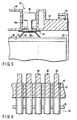
- a music wire 53 is used in place of the thin plate used in each of Examples 1 and 2, and the flange 42 is provided with a hook 54 for fixing the music wire 53, as shown in FIG. 5.
- the hook 54 which is formed integral with the flange 42, is shaped L in cross section. However, the shape of the hook 54 is not particularly limited. Also, a hole through which extends the music wire 53 is formed in the side wall of the hook 54, and a knot 55 is formed inside the hook 54 so as to prevent the edge portion of the music wire 53 from being withdrawn from the hole of the hook 54.
- Example 3 the weight of the entire module can be decreased with a simple construction as in Example 1, making it possible to ensure a sufficiently large effective area ratio.
- Example 3 A fuel cell stack of Example 3 is shown in FIG. 6. Those portions of the fuel cell stack which are equal to those shown in FIGS. 1 to 3 are denoted by the same reference numerals so as to avoid an overlapping description.
- Example 4 a plurality of hooks 56 are formed integral with the flange 42 in the side wall of the flange 42. As shown in the drawing, the continuous music wire 53 is alternately wound about the upper and lower hooks 56. Finally, both end portions of the music wire 53 are joined to each other.
- Example 4 produces effects similar to those produced in Example 3.
Landscapes
- Life Sciences & Earth Sciences (AREA)
- Engineering & Computer Science (AREA)
- Manufacturing & Machinery (AREA)
- Sustainable Development (AREA)
- Sustainable Energy (AREA)
- Chemical & Material Sciences (AREA)
- Chemical Kinetics & Catalysis (AREA)
- Electrochemistry (AREA)
- General Chemical & Material Sciences (AREA)
- Fuel Cell (AREA)
Description
- The present invention relates to a fuel cell stack prepared by making integral a fuel cell laminate body consisting of a plurality of solid polymer type fuel cells each having a solid polymer membrane by a fastening means.
- In recent years, the number of motor cars using gasoline engines has rapidly increased such that about two motor cars are owned nowadays by each family. Naturally, the exhaust gas discharged from the motor car attracts social attentions in relation to the air pollution problem. Under the circumstances, vigorous studies are being made in an attempt to use a fuel cell as a power source of a motor that is used in place of the internal combustion engine. The air pollution problem need not be worried about in the motor car using the fuel cell, which does not use a fossil fuel. In addition, noise is scarcely generated from the motor using the fuel cell. Also, the motor using the fuel cell is advantageous over the internal combustion engine in the energy recovery rate.
- In using the fuel cell in a motor car, it is desirable for the fuel cell and the auxiliary facilities to be as small as possible, though an unduly large output is not required. Such being the situation, PEFC (polymer electrolyte fuel cell), in which a solid polymer membrane is sandwiched between two kinds of electrodes and these electrodes are wrapped in a separator, attracts attentions among various fuel cells.
- FIG. 7 shows the basic construction of a solid polymer type fuel cell. As shown in the drawing, a cell body 1 comprises a
solid polymer membrane 2. Anoxygen electrode 3 and ahydrogen electrode 4 are attached to both surfaces of thesolid polymer membrane 2 to form an integral structure. The integral structure is prepared by attaching theoxygen electrode 3 and thehydrogen electrode 4 to both surfaces of thesolid polymer membrane 2, followed by applying a hot press to the resultant structure. Areaction membrane 5a and agas diffusion membrane 6a are attached to both surfaces of theoxygen electrode 3 such that thereaction membrane 5a is in contact with thesolid polymer membrane 2. Likewise, areaction membrane 5b and agas diffusion membrane 6b are attached to both surfaces of thehydrogen electrode 4 such that thereaction membrane 5b is in contact with thesolid polymer membrane 2. The cell reaction takes place mainly between thesolid polymer membrane 2 and thereaction membranes oxygen supply grooves 7a is attached to the surface of theoxygen electrode 3. Likewise, aseparator 8 havinghydrogen supply grooves 8a is attached to the surface of thehydrogen electrode 4. - In the fuel cell of the particular construction, oxygen and hydrogen introduced through the
oxygen supply grooves 7a and thehydrogen supply grooves 8a are supplied through thegas diffusion membranes reaction membranes solid polymer membrane 2 and thereaction membrane 5a and at the interface B between thesolid polymer membrane 2 and thereaction membrane 5b: - Reaction at interface A:
(1/2)O2 + 2H+ → H2O
- Reaction at interface B:
H2 → 2H+ → 2e-
- The hydrogen ions (2H+) generated at the interface B flow from the
hydrogen electrode 4 into theoxygen electrode 3 through thesolid polymer membrane 2. On the other hand, the electrons (2e-) generated at the interface B flow from thehydrogen electrode 4 into theoxygen electrode 3 through aload 9 so as to obtain an electric energy. - In the fuel cell of the construction described above, it is necessary for the
separators 7 and 8 to supply an oxidizing gas and a fuel gas to the back surfaces of theoxygen electrode 3 and thehydrogen electrode 4, respectively, uniformly and in a completely separated manner. Also, it is necessary for the fuel cell to collect efficiently the electivity generated by the reaction. Further, since heat is generated by the cell reaction, it is necessary to release the reaction heat through the gas separators in order to stabilize the power generating operation. Various separators are proposed for meeting these requirements. FIG. 8 exemplifies the PEFC structure (fuel cell laminate body) using a plurality of separators S. In the fuel cell stack of the construction shown in the drawing, a fuelgas supply plate 19 is attached to an oxidizing gas supply plate 20 such that a fluid passageway 21 is defined between thesesupply plates 19 and 20. A cooling water is circulated through the fluid passageway 21 to suppress the temperature elevation caused by the reaction heat generated at the boundaries between the oxygen electrode and the solid polymer electrolyte plate and between the hydrogen electrode and the solid polymer electrolyte plate. - It was customary in the past to assemble the
fuel cell stack 11 as shown in, for example, FIGS. 9 and 11. Incidentally, FIG. 11 is a plan view showing thefuel cell stack 11 shown in FIG. 9. Thefuel cell stack 11 comprises a plurality ofunit cells 10 stacked one upon the other in the vertical direction and upper andlower flanges unit cell 10 and positioned on the upper and lower surfaces, respectively, of the stack of theunit cells 10. Each of these upper andlower flanges unit cells 10. Fasteningbolts 14 are inserted into the bolt holes to permit thesebolts 14 to extend through the upper andlower flanges bolts 14 so as to fasten the stack of theunit cells 10 held between the upper andlower flanges Reference numerals flanges fuel cell stack 11. Also,reference numerals flanges fuel cell stack 11. - The conventional fuel cell laminate body is assembled as shown in, for example, FIG. 10 to constitute the
fuel cell stack 11. The stack shown in FIG. 10 is equal to the stack shown in FIG. 9, except that, in FIG. 10, theflanges unit cell 10. - The conventional fuel cell stack is defective in that, since a large number of
fastening bolts 14 are used for fastening the fuel cell laminate body, the effective area ratio of the fuel cell stack is low. For example, where the fuel cell stack shown in FIG. 9 including the region of thefastening bolts 14 has a length Y1 of, for example, 140 mm, and a width T1 of, for example 120 mm, the region of theunit cell 10, which is shaded in FIG. 11, has a length Y2 of, for example, 130 nm, and width T2 of, for example, 100 nm. It follows that the effective area ratio is: T2·Y2/T1·Y1 = {(100 × 130)/(120 × 140)} × 100 ≒ 77%. Also, the conventional fuel cell stack is rendered heavier and more bulky. - Fuel cells are also disclosed in Japanese Patent Disclosure (Kokai) No. 10-189025 and Japanese Patent Disclosure No. 9-92324. JP '025 is directed to a fuel cell in which the direction of the pressurizing force applied to the fuel cell stack housed in a case is kept parallel to the stacking direction of the unit cells so as to prevent the gas sealing properties from being deteriorated and to prevent the contact resistance from being increased. On the other hand, JP '324 is directed to a fuel cell module and a fuel cell in which pushing force is applied to a laminate body of unit cells without using a fastening tool such as a bolt so as to make compact the fuel cell module and the fuel cell.
- The Japanese patent application (Kokai) publication no. 10-134834 discloses a fuel cell comprising a battery layered body, an upper portion collecting plate having a clamping stud, a lower portion collecting plate having a clamping stud, a fastening means and fuel cell having a nut. The clamping studs are projecting over the battery layered body in order to allow bolts to project through the clamping studs for fastening.
- Japanese patent application (Kokai) publication no. 11-204129 discloses a layer build fuel cell comprising a cell laminate, clamping plates having flanges, clamping studs, and springs. The flanges are projecting over the cell laminate in order to allow bolts to project through the flanges for fastening.
- Japanese patent application (Kokai) publication no. 61-204129 discloses a clamping device of a layer-build type fuel cell comprising a fuel cell body, a pushing upper plate, a pushing rod, and springs. The pushing upper plate and pushing lower plate are connected to each other with bolts and fuel cell body is fastened in vertical direction by use of the springs.
- An object of the present invention is to provide a fuel cell stack, comprising a fastening means including support members equipped with flanges arranged at upper and lower edge portions of a fuel cell laminate body, connecting members joined to the support members and extending in the vertical direction of the fuel cell laminate body, and fastening tools for fastening the support members in the vertical direction of the fuel cell laminate body. The particular construction of the present invention makes it possible to Increase the effective area ratio of the fuel cell stack, compared with the conventional fuel cell stack In additional, the fuel cell stack of the present invention is light in weight and small in outer size.
- According to the present invention, there is provided a fuel cell stack, comprising a fuel cell laminate body prepared by laminating a plurality of unit cells each having a solid polymer membrane sandwiched between electrodes and a fastening means for fastening the fuel cell laminate body in the direction of lamination of the unit cells, wherein the fastening means includes support members adjacent to the uppest and lowest unit cell of the stacked fuel cell laminate body equipped with flanges and arranged at the upper and lower edges of the fuel cell laminate body, connecting members joined to the support members at, and fastening tools for fastening the support members in the vertical direction of the fuel cell laminate body. The connecting member is a plate-like member made of stainless steel of consists of a music wire. The connecting member is folded at the upper and lower edges towards the flanges and jointly fixed to the support members inside the area of the outer perimeter of the fuel cell laminate body.
- This summary of the invention does not necessarily describe all necessary features so that the invention may also be a sub-combination of these described features.
- The invention can be more fully understood from the following detailed description when taken in conjunction with the accompanying drawings, in which:
- FIG. 1
- is an oblique view, partly broken away, showing a fuel cell stack according to Example 1 of the present invention:
- FIG. 2
- is a plan view showing the fuel cell stack shown in FIG. 1;
- FIG. 3
- is a cross sectional view showing in a magnified fashion a gist portion X of the fuel cell stack shown in FIG. 1;
- FIG. 4
- is a cross sectional view showing a gist portion of a fuel cell stack according to Example 2 of the present invention.
- FIG. 5
- is a cross sectional view showing a gist portion of a fuel cell stack according to Example 3 of the present invention:
- FIG. 6
- is a cross sectional view showing a gist portion of a fuel cell stack according to Example 4 of the present invention;
- FIG. 7
- shows the principle of a solid polymer type fuel cell;
- FIG. 8
- shows the construction of a solid polymer type fuel cell stack;
- FIG. 9
- is an oblique view showing a conventional fuel cell stack;
- FIG. 10
- is an oblique view showing another conventional fuel cell stack; and
- FIG. 11
- is a plan view showing the conventional fuel cell stack shown in FIG. 9.
- The fuel cell stack of the present invention comprises a fuel cell laminate body consisting of a plurality of unit cells laminated one upon the other, each unit cell consisting of electrodes arranged on both sides a solid polymer membrane, and fastening means for fastening the fuel cell laminate body in the laminating direction of said unit cells, wherein said fastening means includes support members each provided with a flange and arranged on the upper and lower ends of the fuel cell laminate body, connecting members joined to said support members and arranged to extend along the side surfaces of the fuel cell laminate body, and fastening means for fastening said support members in the laminating direction of the fuel cell laminate body.
- The present invention will now be described more in detail.
- The fuel cell stack of the present invention comprises a fastening means for fastening a fuel cell laminate body consisting of a plurality of unit cells laminated one upon the other in the direction of lamination of the unit cells. Therefore, for simplifying the construction, it is desirable for the upper and lower edge portions of the fastening member to be equal to each other in construction, though it is not absolutely necessary for these upper and lower edge portions to be equal to each other in construction.
- The fastening member includes support members equipped with flanges arranged at upper and lower edge portions of a fuel cell laminate body, connecting members joined to the support members and extending in the vertical direction of the fuel cell laminate body, and fastening tools for fastening the support members in the vertical direction of the fuel cell laminate body.
- The support member equipped with flanges includes, for example, a hollow body, a rib arranged within the hollow body, flanges joined to both sides of the hollow body, and a pushing member mounted within the hollow body. The rib is arranged between the upper and lower walls of the hollow body so as to reinforce the hollow body. The pushing member comprises a dish spring, a holding plate arranged above the dish spring, and a dish spring bolt arranged above the holding plate, as shown in, for example, FIG. 3. It is desirable for the pushing member to be arranged in good balance to permit the pushing force of the fastening member to be transmitted uniformly to the pushing surface of the fuel cell laminate body. Incidentally, a leaf spring, a spiral spring, etc. can be used in place of the dish spring as far as the pushing force of the pushing member can be transmitted uniformly to the pushing surface of the fuel cell stack.
- In the present invention, a plate-like member made of a stainless steel, a musical wire, etc. can be used as the connection member. The plate-like member can be joined to the support member by welding or by a mechanical engagement. A single musical wire may be joined to the support members at the upper and lower edge portions of the fuel cell laminate body. Alternatively, a plurality of musical wires may be joined to the support members.
- In the present invention, it is desirable for the fastening tool, which serves to fasten the fuel cell laminate body in the direction of lamination of the unit cells, to be capable of transmitting an appropriate pushing force to the flange portion of the support member. To be more specific, it is desirable for the fastening tool to be constructed such that the connection member is interposed between a holding tool provided with a threaded hole and the flange, and the pushing force generated by the fixing bolt is transmitted to the fuel cell laminate body, as shown in FIG. 3. Alternatively, it is possible to employ the construction to use the holding member consisting of two kinds of holding tools and the fixing bolt as shown in FIG. 4. Further, it is possible to employ the construction to use a hook for fixing a single or a plurality of music wires, as shown in FIG. 5 or 6.
- Some Examples of the present invention will now be described with reference to the accompanying drawings.
- FIGS. 1 to 3 collectively show a fuel cell stack of Example 1 of the present invention, wherein FIG. 1 is an oblique view, partly broken away, showing a fuel cell stack according to Example 1 of the present invention, FIG. 2 is a plan view showing the fuel cell stack shown in FIG. 1 excluding the support member, and FIG. 3 is a cross sectional view showing in a magnified fashion a gist portion X shown in FIG. 1. The fastening means used in Example 1 extends through the fuel cell stack. The construction of the fastening means on the upper surface of the fuel cell stack is equal to that on the lower surface of the fuel cell stack.
-
Reference numeral 31 shown in FIG. 1 denotes a fuel cell laminate body prepared by laminating a plurality ofunit cells 32 in a vertical direction. Only the uppermost andlowermost unit cells 32 are shown in FIG. 1 for simplifying the drawing. Theunit cell 32 comprises a solid polymer membrane (not shown), an oxygen electrode (not shown) arranged on one surface of the solid polymer membrane, a hydrogen electrode (not shown) arranged on the other surface of the solid polymer membrane, and separators arranged on the outer surfaces of the oxygen electrode and the hydrogen electrode. The basic construction and function of theunit cell 32 are equal to those described previously in conjunction with FIG. 7. First holdingplates 30 are arranged on the upper and lower surfaces of the fuelcell laminate body 31. Reactant gas supply holes 33 for supplying a reactant gas into theunit cells 32, reaction gas discharge holes 34 for discharging the reaction gas, a coolingwater supply hole 35 for supplying a cooling water into theunit cells 32 and a coolingwater discharge hole 36 are formed to extend vertically through the holdingplates 30 and the fuelcell laminate body 31. - The fuel
cell laminate body 31 is fastened by the fastening means in the direction of lamination. The fastening means comprisessupport members 37 equipped with flanges and arranged on the upper and lower surfaces of thelaminate body 31, connecting members (thin plates) 38 made of stainless steel thin plates each having a thickness of 1.0 mm and fixed to the edge portions of the upper andlower support members 37, and afastening tool 39 for fastening the connection members (thin plates) 38 in the vertical direction of thelaminate body 31. The fuelcell laminate body 31 and the fastening means collectively form afuel cell stack 61. - The
support member 37 comprises a plate-likehollow body 40, arib 41 arranged within thehollow body 40,flanges 42 joined to both edges of thehollow body 40, and apush control member 43 arranged within thehollow body 40. Thepush control member 43 comprises adish spring 44 acting as a pushing force adjusting member and arranged between the bottom surface of thehollow body 40 and the upper surface of thestack 31, asecond holding plate 45 arranged on thedish spring 44, and adish spring bolt 46. For arranging thedish spring bolt 46, abolt hole 40b is made in arecess 40a formed at a portion of thehollow body 40, and thedish spring bolt 46 is arranged by utilizing thebolt hole 40b so as to be positioned above thedish spring 44. - The
fastening tool 39 comprises a holding tool 47 (see FIG. 4) for holding thethin plates 38 folded at the upper and lower edges and fixing bolts 48 (see FIG. 3) for fastening the holding tool 47, thethin plates 38 and theflanges 42. The fixingbolt 48 is engaged by screw engagement with threaded holes 47a made in the holding tool 47 and theflange 42 and with threaded hole 38a made in thethin plate 38. If thefastening bolt 48 is fastened, pushing force is exerted on theflange 42 and, then, on thedish spring 44 positioned below thedish spring bolt 46, with the result that thefuel cell stack 31 is fastened in the direction of lamination. - As described above, the fuel cell stack in Example 1 of the present invention comprises the fastening means consisting of the
support members 37 equipped with flanges arranged at the upper and lower edge portions of the fuelcell laminate body 31, thethin plates 38 joined to thesupport members 37 at the upper and lower edges of the fuel cell laminate body, and thefastening tool 39 for fastening the thin plates in the vertical direction of the fuelcell laminate body 31. Thesupport member 37 comprises the plate-likehollow body 40, therib 41 arranged within thehollow body 40, theflanges 42 jointed to both edges of thehollow body 40, and thepush control member 43 arranged within thehollow body 40. Further, thefastening tool 39 comprises the holding tool 47 for holding thethin plate 38 folded at the edge portions, the fixingbolt 48 for fastening the holding tool 47, thethin plate 38 and theflange 42. - In the fuel cell module of Example 1, the
fuel cell stack 31 is fastened by the fixingbolt 48 for fastening thethin plate 38 and thedish spring bolt 44 for uniformly pushing the end surface of the stack without using such a long bolt as used in the prior art. As a result, the entire module is made lightweight, and the effective area ratio can be increased. - As a matter of fact, the effective area ratio of the fuel cell stack in Example 1 was determined as in FIG. 2. Specifically, the stack had a length Y1 of 130 mm and a width T1 of 112 mm. On the other hand, the cell region shaded in FIG. 2 had a length Y1 of 130 mm and a width T2 Of 100 mm. It follows that the effective area ratio, i.e., Y1·T2/Y1·T1 × 100 (%), was {(130 × 100)/(130 × 112)} X 100 ≒ 89%. On the other hand, the effective area ratio for the conventional fuel cell stack was about 77% as described previously. Clearly, the fuel cell stack of the present invention permits improving the effective area ratio. In addition, the present invention permits diminishing the weight and outer size of the fuel cell stack.
- In Example 1, a fixing bolt is used for fixing the thin plate to the flange. However, it is also possible to use welding for fixing the thin plate to the flange. Further, the thickness and material of the thin plate are not limited to those described previously.
- Also, in Example 1, the push control member using a dish spring was used in 5 points. However, the number of push control members is not particularly limited, as far as the force produced by the fixing bolt is transmitted uniformly onto the upper and lower ends of the fuel cell stack. For example, it suffices to use only one push control member or four push control members as far as the force produced by the fixing bolt is transmitted uniformly onto the upper and lower ends of the fuel cell stack. Further, the dish spring can be replaced by, for example, a spiral spring.
- A fuel cell stack of Example 2 is shown in FIG. 4. Those portions of the fuel cell stack which are equal to those shown in FIGS. 1 to 3 are denoted by the same reference numerals so as to avoid an overlapping description. In Example 2, the holding tool 47 comprises a
lower holding member 52 provided with anopening 52a into which a fixingbolt 51 is inserted and an upper holdingmember 53 arranged above the lower holdingmember 52 and provided with abolt hole 53a that is engaged with the fixingbolt 51. The upper edge portion of thethin plate 38 is folded at the edge portion of the lower holdingmember 52 to extend far into the clearance between the lower andupper holding members bolt 51 is screwed through thebolt hole 53a of the upper holdingmember 53 so as to permit thethin plate 38 to be partly pushed toward the flange within anopening 52a of the lower holdingmember 52, thereby strongly fastening thethin plate 38. - If the fixing
bolt 51 is fastened in Example 2, the fastening force is transmitted to thesecond holding plate 45 through the holding tool 47 and theflange 42. Further, the fastening force exerts on thedish spring 44 positioned below thebolt 46. As a result, the unit cells of thefuel cell stack 31 is pushed in the direction of lamination. Therefore, the weight of the entire module can be decreased in Example 2 as in Example 1, making it possible to ensure a sufficiently large effective area ratio. - In Example 2, the lower holding
member 52 is welded to theflange 42 for forming an integral structure. Alternatively, the integral structure can be formed by, for example, molding. - A fuel cell stack of Example 3 is shown in FIG. 5. Those portions of the fuel cell stack which are equal to those shown in FIGS. 1 to 3 are denoted by the same reference numerals so as to avoid an overlapping description. In Example 3, a
music wire 53 is used in place of the thin plate used in each of Examples 1 and 2, and theflange 42 is provided with ahook 54 for fixing themusic wire 53, as shown in FIG. 5. Thehook 54, which is formed integral with theflange 42, is shaped L in cross section. However, the shape of thehook 54 is not particularly limited. Also, a hole through which extends themusic wire 53 is formed in the side wall of thehook 54, and aknot 55 is formed inside thehook 54 so as to prevent the edge portion of themusic wire 53 from being withdrawn from the hole of thehook 54. - In Example 3, the weight of the entire module can be decreased with a simple construction as in Example 1, making it possible to ensure a sufficiently large effective area ratio.
- A fuel cell stack of Example 3 is shown in FIG. 6. Those portions of the fuel cell stack which are equal to those shown in FIGS. 1 to 3 are denoted by the same reference numerals so as to avoid an overlapping description. In Example 4, a plurality of
hooks 56 are formed integral with theflange 42 in the side wall of theflange 42. As shown in the drawing, thecontinuous music wire 53 is alternately wound about the upper and lower hooks 56. Finally, both end portions of themusic wire 53 are joined to each other. - Example 4 produces effects similar to those produced in Example 3.
Claims (7)
- A fuel cell stack (61), comprising a fuel cell laminate body (31) prepared by laminating a plurality of unit cells (32) each having a solid polymer membrane sandwiched between electrodes and a fastening means for fastening the fuel cell laminate body in the direction of lamination of the unit cells (32),
characterized in that the fastening means includes support members (37) adjacent to the uppest and lowest unit cell (32) of the stacked fuel cell laminate body (31) equipped with flanges (42) and arranged at the upper and lower edges of the fuel cell laminate body (31), connecting members (38) joined to the support members (37) and fastening tools (39) for fastening the support members (37) in the vertical direction of the fuel cell laminate body (31), and that said connecting member (38) is a plate-like member made of stainless steel or that said connecting member (38) consists of a music wire (53), said connecting member (38) being folded at the upper and lower edges towards the flanges (42) and jointly fixed to the support members (37) inside the area of the outer perimeter of the fuel cell laminate body (31). - The fuel cell stack (61) according to claim 1, characterized In that said support member (37) comprises a hollow body (40), a rib (41) arranged within said hollow body (40), flanges joined to both ends of said hollow body (40), and a pushing force control member arranged within the hollow body (40).
- The fuel cell stack (61) according to claim 1, characterized in that said fastening tool (39) is a bolt (48) joined by screw engagement to the flange portion of said support member (37).
- The fuel cell stack (61) according to claim 2, characterized in that said pushing force adjusting member is selected from the group consisting of a dish plate, a leaf spring and a spiral spring.
- The fuel cell stack (61) according to claim 1, characterized in that said plate-like member is bonded to said support member (37).
- The fuel cell stack (61) according to claim 1, characterized in that both ends of said music wire (53) are fixed to the flange of said support member (37).
- The fuel cell stack (61) according to claim 1, characterized in that said music wire (53) is alternately wound about a plurality of hooks formed integral with the upper and lower flanges of said support member (37), and both end portions of the music wire (53) are finally joined to each other.
Applications Claiming Priority (2)
| Application Number | Priority Date | Filing Date | Title |
|---|---|---|---|
| JP10918699A JP4220615B2 (en) | 1999-04-16 | 1999-04-16 | Fuel cell stack |
| JP10918699 | 1999-04-16 |
Publications (4)
| Publication Number | Publication Date |
|---|---|
| EP1045468A2 EP1045468A2 (en) | 2000-10-18 |
| EP1045468A8 EP1045468A8 (en) | 2001-07-25 |
| EP1045468A3 EP1045468A3 (en) | 2003-05-28 |
| EP1045468B1 true EP1045468B1 (en) | 2006-01-11 |
Family
ID=14503828
Family Applications (1)
| Application Number | Title | Priority Date | Filing Date |
|---|---|---|---|
| EP00108120A Expired - Lifetime EP1045468B1 (en) | 1999-04-16 | 2000-04-13 | Fuel cell stack with fastening means |
Country Status (5)
| Country | Link |
|---|---|
| US (1) | US6361895B1 (en) |
| EP (1) | EP1045468B1 (en) |
| JP (1) | JP4220615B2 (en) |
| CA (1) | CA2305855C (en) |
| DE (1) | DE60025409T2 (en) |
Families Citing this family (16)
| Publication number | Priority date | Publication date | Assignee | Title |
|---|---|---|---|---|
| US6613641B1 (en) * | 2001-01-17 | 2003-09-02 | International Business Machines Corporation | Production of metal insulator metal (MIM) structures using anodizing process |
| JP4672892B2 (en) | 2001-03-30 | 2011-04-20 | 本田技研工業株式会社 | Fuel cell stack |
| US6862801B2 (en) | 2001-11-30 | 2005-03-08 | Ballard Power Systems Inc. | Systems, apparatus and methods for isolating, compressing and/or retaining the structure of a fuel cell stack |
| US7037618B2 (en) * | 2002-06-05 | 2006-05-02 | Lynntech, Inc. | Apparatus and method for compressing a stack of electrochemical cells |
| US7163761B2 (en) * | 2002-11-14 | 2007-01-16 | 3M Innovative Properties Company | Fuel cell stack |
| US20040096715A1 (en) * | 2002-11-14 | 2004-05-20 | 3M Innovative Properties Company | Liquid cooled fuel cell stack |
| KR100488875B1 (en) * | 2002-11-18 | 2005-05-11 | 현대자동차주식회사 | Assembling structure of electrochemical fuel cell stack |
| US20040214067A1 (en) * | 2002-12-04 | 2004-10-28 | Chris Boyer | Assembling sub-stacks of electrochemical cells |
| JP2004362940A (en) * | 2003-06-04 | 2004-12-24 | Yuasa Corp | Fuel cell stack |
| JP2005276482A (en) * | 2004-03-23 | 2005-10-06 | Nissan Motor Co Ltd | FUEL CELL STACK COMPOSITE, METHOD FOR PRODUCING FUEL CELL STACK, AND FUEL CELL STACK |
| DE102006028439B4 (en) | 2006-06-21 | 2016-02-18 | Elringklinger Ag | Fuel cell stack and method for producing a fuel cell stack |
| JP5178061B2 (en) * | 2007-06-25 | 2013-04-10 | 株式会社日立製作所 | Fuel cell |
| US20090162726A1 (en) * | 2007-12-20 | 2009-06-25 | Kemal Ozgur | Compression apparatus for fuel cell stack |
| JP5737198B2 (en) * | 2012-01-23 | 2015-06-17 | トヨタ自動車株式会社 | Fuel cell |
| JP6018463B2 (en) * | 2012-09-18 | 2016-11-02 | 株式会社東芝 | Fuel cell |
| BR112020001419A2 (en) * | 2017-07-24 | 2020-07-28 | Nuvera Fuel Cells, LLC | fuel cell compression systems and methods |
Family Cites Families (8)
| Publication number | Priority date | Publication date | Assignee | Title |
|---|---|---|---|---|
| JPS61248368A (en) * | 1985-04-25 | 1986-11-05 | Mitsubishi Electric Corp | Clamping device of layer-built type fuel cell |
| JP3135991B2 (en) * | 1992-06-18 | 2001-02-19 | 本田技研工業株式会社 | Fuel cell and fuel cell stack tightening method |
| JP3547918B2 (en) * | 1996-10-29 | 2004-07-28 | 株式会社東芝 | Fuel cell |
| JPH10189025A (en) * | 1996-12-20 | 1998-07-21 | Toyota Motor Corp | Fuel cell |
| US6190793B1 (en) * | 1997-07-16 | 2001-02-20 | Ballard Power Systems Inc. | Electrochemical fuel cell stack with an improved compression assembly |
| JPH11204129A (en) * | 1998-01-08 | 1999-07-30 | Fuji Electric Co Ltd | Stacked fuel cell |
| JP3420508B2 (en) * | 1998-08-20 | 2003-06-23 | 松下電器産業株式会社 | Polymer electrolyte fuel cell |
| JP3425086B2 (en) * | 1998-08-20 | 2003-07-07 | 松下電器産業株式会社 | Polymer electrolyte fuel cell, system using the same, and method of installing the same |
-
1999
- 1999-04-16 JP JP10918699A patent/JP4220615B2/en not_active Expired - Lifetime
-
2000
- 2000-04-13 EP EP00108120A patent/EP1045468B1/en not_active Expired - Lifetime
- 2000-04-13 DE DE60025409T patent/DE60025409T2/en not_active Expired - Fee Related
- 2000-04-14 US US09/549,003 patent/US6361895B1/en not_active Expired - Lifetime
- 2000-04-14 CA CA002305855A patent/CA2305855C/en not_active Expired - Fee Related
Also Published As
| Publication number | Publication date |
|---|---|
| CA2305855A1 (en) | 2000-10-16 |
| DE60025409D1 (en) | 2006-04-06 |
| US6361895B1 (en) | 2002-03-26 |
| EP1045468A8 (en) | 2001-07-25 |
| DE60025409T2 (en) | 2006-07-13 |
| JP2000299121A (en) | 2000-10-24 |
| JP4220615B2 (en) | 2009-02-04 |
| EP1045468A2 (en) | 2000-10-18 |
| EP1045468A3 (en) | 2003-05-28 |
| CA2305855C (en) | 2004-06-01 |
Similar Documents
| Publication | Publication Date | Title |
|---|---|---|
| US6361895B1 (en) | Fuel cell stack with fastening means including support members and flanges | |
| CN115020887B (en) | Single batteries, power battery packs and electric vehicles | |
| CN1087506C (en) | Molten carbon fuel cell and power generation system including the same | |
| US9985310B2 (en) | Multi-function solid oxide fuel cell bundle and method of making the same | |
| JP4630529B2 (en) | Fuel cell system | |
| US9711819B2 (en) | Mount structure for fuel cell stack | |
| US20010049039A1 (en) | Fuel cell stack integrated with a waste energy recovery system | |
| JP2006236826A (en) | Battery pack | |
| AU1052999A (en) | Solid electrolyte fuel cell | |
| CN1075033A (en) | Drive the on-board charging system of the storage battery of electric vehicles | |
| KR101089160B1 (en) | Fuel cell stack assembly | |
| EP1387428B1 (en) | Manifold sizing and configuration for a fuel cell stack | |
| JP2003297377A (en) | In-vehicle fuel cell | |
| US6127055A (en) | Multi-source electrical drive system | |
| JP2006040753A (en) | Vehicle-mounted fuel cell | |
| KR100569133B1 (en) | Fuel cell module for electric vehicle | |
| JP5086581B2 (en) | Fuel cell stack | |
| JP4062798B2 (en) | Fuel cell and fuel cell assembly | |
| KR100514375B1 (en) | A device for tightening stacks of fuel cell in electric vehicles | |
| US20250233289A1 (en) | Battery cell, battery, and electric device | |
| JP2008103210A (en) | Fuel cell and fuel cell stack | |
| WO2007026955A2 (en) | Fuel cell | |
| JP2008078071A (en) | Fuel cell stack | |
| JP2006073393A (en) | Hydrogen separation membrane fuel cell and unit cell thereof | |
| JP2006066256A (en) | Fuel cell stack |
Legal Events
| Date | Code | Title | Description |
|---|---|---|---|
| PUAI | Public reference made under article 153(3) epc to a published international application that has entered the european phase |
Free format text: ORIGINAL CODE: 0009012 |
|
| 17P | Request for examination filed |
Effective date: 20000420 |
|
| AK | Designated contracting states |
Kind code of ref document: A2 Designated state(s): AT BE CH CY DE DK ES FI FR GB GR IE IT LI LU MC NL PT SE |
|
| AX | Request for extension of the european patent |
Free format text: AL;LT;LV;MK;RO;SI |
|
| RIN1 | Information on inventor provided before grant (corrected) |
Inventor name: KAJIWARA, TOMOYUKI, HIROSHIMA R & D CENTER Inventor name: ITOU, HIDEKI, HIROSHIMA R & D CENTER Inventor name: MORIGA, TAKUYA Inventor name: KOBAYASHI, TOSHIROU, HIROSHIMA R & D CENTER |
|
| RIN1 | Information on inventor provided before grant (corrected) |
Inventor name: MORIGA, TAKUYA, HIROSHIMA R & D CENTER Inventor name: KAJIWARA, TOMOYUKI, HIROSHIMA R & D CENTER Inventor name: KOBAYASHI, TOSHIROU, HIROSHIMA R & D CENTER Inventor name: ITOU, HIDEKI, HIROSHIMA R & D CENTER |
|
| PUAL | Search report despatched |
Free format text: ORIGINAL CODE: 0009013 |
|
| AK | Designated contracting states |
Designated state(s): AT BE CH CY DE DK ES FI FR GB GR IE IT LI LU MC NL PT SE |
|
| AX | Request for extension of the european patent |
Extension state: AL LT LV MK RO SI |
|
| AKX | Designation fees paid |
Designated state(s): DE FR GB IT |
|
| 17Q | First examination report despatched |
Effective date: 20040915 |
|
| GRAP | Despatch of communication of intention to grant a patent |
Free format text: ORIGINAL CODE: EPIDOSNIGR1 |
|
| GRAS | Grant fee paid |
Free format text: ORIGINAL CODE: EPIDOSNIGR3 |
|
| GRAA | (expected) grant |
Free format text: ORIGINAL CODE: 0009210 |
|
| AK | Designated contracting states |
Kind code of ref document: B1 Designated state(s): DE FR GB IT |
|
| REF | Corresponds to: |
Ref document number: 60025409 Country of ref document: DE Date of ref document: 20060406 Kind code of ref document: P |
|
| ET | Fr: translation filed | ||
| PLBE | No opposition filed within time limit |
Free format text: ORIGINAL CODE: 0009261 |
|
| STAA | Information on the status of an ep patent application or granted ep patent |
Free format text: STATUS: NO OPPOSITION FILED WITHIN TIME LIMIT |
|
| 26N | No opposition filed |
Effective date: 20061012 |
|
| PGFP | Annual fee paid to national office [announced via postgrant information from national office to epo] |
Ref country code: DE Payment date: 20070405 Year of fee payment: 8 |
|
| PGFP | Annual fee paid to national office [announced via postgrant information from national office to epo] |
Ref country code: GB Payment date: 20070411 Year of fee payment: 8 |
|
| PGFP | Annual fee paid to national office [announced via postgrant information from national office to epo] |
Ref country code: IT Payment date: 20070529 Year of fee payment: 8 |
|
| PGFP | Annual fee paid to national office [announced via postgrant information from national office to epo] |
Ref country code: FR Payment date: 20070411 Year of fee payment: 8 |
|
| GBPC | Gb: european patent ceased through non-payment of renewal fee |
Effective date: 20080413 |
|
| PG25 | Lapsed in a contracting state [announced via postgrant information from national office to epo] |
Ref country code: DE Free format text: LAPSE BECAUSE OF NON-PAYMENT OF DUE FEES Effective date: 20081101 |
|
| REG | Reference to a national code |
Ref country code: FR Ref legal event code: ST Effective date: 20081231 |
|
| PG25 | Lapsed in a contracting state [announced via postgrant information from national office to epo] |
Ref country code: FR Free format text: LAPSE BECAUSE OF NON-PAYMENT OF DUE FEES Effective date: 20080430 |
|
| PG25 | Lapsed in a contracting state [announced via postgrant information from national office to epo] |
Ref country code: GB Free format text: LAPSE BECAUSE OF NON-PAYMENT OF DUE FEES Effective date: 20080413 |
|
| PG25 | Lapsed in a contracting state [announced via postgrant information from national office to epo] |
Ref country code: IT Free format text: LAPSE BECAUSE OF NON-PAYMENT OF DUE FEES Effective date: 20080413 |