EP1045140B1 - Gear box for a wind turbine - Google Patents
Gear box for a wind turbine Download PDFInfo
- Publication number
- EP1045140B1 EP1045140B1 EP00107377A EP00107377A EP1045140B1 EP 1045140 B1 EP1045140 B1 EP 1045140B1 EP 00107377 A EP00107377 A EP 00107377A EP 00107377 A EP00107377 A EP 00107377A EP 1045140 B1 EP1045140 B1 EP 1045140B1
- Authority
- EP
- European Patent Office
- Prior art keywords
- gear
- stage
- rotor
- planet carrier
- housing
- Prior art date
- Legal status (The legal status is an assumption and is not a legal conclusion. Google has not performed a legal analysis and makes no representation as to the accuracy of the status listed.)
- Expired - Lifetime
Links
Images
Classifications
-
- F—MECHANICAL ENGINEERING; LIGHTING; HEATING; WEAPONS; BLASTING
- F16—ENGINEERING ELEMENTS AND UNITS; GENERAL MEASURES FOR PRODUCING AND MAINTAINING EFFECTIVE FUNCTIONING OF MACHINES OR INSTALLATIONS; THERMAL INSULATION IN GENERAL
- F16H—GEARING
- F16H1/00—Toothed gearings for conveying rotary motion
- F16H1/28—Toothed gearings for conveying rotary motion with gears having orbital motion
- F16H1/46—Systems consisting of a plurality of gear trains each with orbital gears, i.e. systems having three or more central gears
-
- F—MECHANICAL ENGINEERING; LIGHTING; HEATING; WEAPONS; BLASTING
- F03—MACHINES OR ENGINES FOR LIQUIDS; WIND, SPRING, OR WEIGHT MOTORS; PRODUCING MECHANICAL POWER OR A REACTIVE PROPULSIVE THRUST, NOT OTHERWISE PROVIDED FOR
- F03D—WIND MOTORS
- F03D15/00—Transmission of mechanical power
-
- F—MECHANICAL ENGINEERING; LIGHTING; HEATING; WEAPONS; BLASTING
- F03—MACHINES OR ENGINES FOR LIQUIDS; WIND, SPRING, OR WEIGHT MOTORS; PRODUCING MECHANICAL POWER OR A REACTIVE PROPULSIVE THRUST, NOT OTHERWISE PROVIDED FOR
- F03D—WIND MOTORS
- F03D15/00—Transmission of mechanical power
- F03D15/10—Transmission of mechanical power using gearing not limited to rotary motion, e.g. with oscillating or reciprocating members
-
- F—MECHANICAL ENGINEERING; LIGHTING; HEATING; WEAPONS; BLASTING
- F03—MACHINES OR ENGINES FOR LIQUIDS; WIND, SPRING, OR WEIGHT MOTORS; PRODUCING MECHANICAL POWER OR A REACTIVE PROPULSIVE THRUST, NOT OTHERWISE PROVIDED FOR
- F03D—WIND MOTORS
- F03D80/00—Details, components or accessories not provided for in groups F03D1/00 - F03D17/00
- F03D80/70—Bearing or lubricating arrangements
-
- F—MECHANICAL ENGINEERING; LIGHTING; HEATING; WEAPONS; BLASTING
- F05—INDEXING SCHEMES RELATING TO ENGINES OR PUMPS IN VARIOUS SUBCLASSES OF CLASSES F01-F04
- F05B—INDEXING SCHEME RELATING TO WIND, SPRING, WEIGHT, INERTIA OR LIKE MOTORS, TO MACHINES OR ENGINES FOR LIQUIDS COVERED BY SUBCLASSES F03B, F03D AND F03G
- F05B2260/00—Function
- F05B2260/40—Transmission of power
- F05B2260/403—Transmission of power through the shape of the drive components
- F05B2260/4031—Transmission of power through the shape of the drive components as in toothed gearing
- F05B2260/40311—Transmission of power through the shape of the drive components as in toothed gearing of the epicyclic, planetary or differential type
-
- F—MECHANICAL ENGINEERING; LIGHTING; HEATING; WEAPONS; BLASTING
- F16—ENGINEERING ELEMENTS AND UNITS; GENERAL MEASURES FOR PRODUCING AND MAINTAINING EFFECTIVE FUNCTIONING OF MACHINES OR INSTALLATIONS; THERMAL INSULATION IN GENERAL
- F16H—GEARING
- F16H1/00—Toothed gearings for conveying rotary motion
- F16H1/28—Toothed gearings for conveying rotary motion with gears having orbital motion
- F16H2001/289—Toothed gearings for conveying rotary motion with gears having orbital motion comprising two or more coaxial and identical sets of orbital gears, e.g. for distributing torque between the coaxial sets
-
- Y—GENERAL TAGGING OF NEW TECHNOLOGICAL DEVELOPMENTS; GENERAL TAGGING OF CROSS-SECTIONAL TECHNOLOGIES SPANNING OVER SEVERAL SECTIONS OF THE IPC; TECHNICAL SUBJECTS COVERED BY FORMER USPC CROSS-REFERENCE ART COLLECTIONS [XRACs] AND DIGESTS
- Y02—TECHNOLOGIES OR APPLICATIONS FOR MITIGATION OR ADAPTATION AGAINST CLIMATE CHANGE
- Y02E—REDUCTION OF GREENHOUSE GAS [GHG] EMISSIONS, RELATED TO ENERGY GENERATION, TRANSMISSION OR DISTRIBUTION
- Y02E10/00—Energy generation through renewable energy sources
- Y02E10/70—Wind energy
- Y02E10/72—Wind turbines with rotation axis in wind direction
Definitions
- the invention relates to a transmission for a wind turbine with the features of the preamble of claim 1.
- Modern wind turbines are becoming increasingly ecological and economic constraints.
- the economy demands that modern wind turbines with conventional Energy generation, e.g. B. by fossil power plants or Nuclear power plants can compete. That sets High performance systems with a low power to weight ratio compact design ahead.
- For pollution and environmental reasons (Noise emission) are the dynamic loads too to reduce.
- the locations should be as possible guarantee continuous and strong wind conditions and to be sparsely populated.
- Offshore systems offer an alternative, which in turn is still due to the high installation costs require more powerful, compact and lighter systems.
- the drive train of known wind turbines (EP-OS 635 639) is made up of the rotor blades with the rotor hub, the rotor shaft with the rotor bearing, a multi-stage Planetary spur gear, a clutch and a generator.
- the rotor blades are connected to the rotor hub and drive the rotor shaft.
- This is in a large rolling bearing recorded that over a machine frame with the Azimuth bearing is connected. In this way, those on the rotor attacking wind forces introduced into the tower.
- This Storage requires a shaft section between the rotor and the transmission.
- the second rotor shaft bearing is from the Gearbox formed, the hollow drive shaft via a Shrink disc is connected to the rotor shaft.
- the gear is also supported by a double-arm torque arm on the machine frame. This well-known wind turbine takes up a lot of space and is therefore in the Performance limited.
- a wind turbine is known from EP-OS 811 764, in which the rotor directly on the planet carrier of a one-stage Planetary gear is attached. This gear and the Generators are mounted on a common machine frame.
- WO 96/11338 includes a two-stage planetary gear two single toothed planetary stages for a wind turbine described.
- the rotor is attached directly to the planet carrier and the rotor is mounted in the gearbox. The further connection of the transmission to the wind turbine is not described.
- the invention has for its object a concept for a To develop wind turbines that are more compact and therefore for higher outputs in a range of around 2.5 - 5 MW at only slightly heavier and more complex construction is suitable.
- the two-stage planetary gear is a compact design reached.
- a particularly compact design is possible if the rotor hub is connected to the gear housing because in In this case, the entire gearbox is housed in the rotor hub can be. Due to the double helical toothing of the drive stage and the helical step planets are the output step achieve higher translations in a smaller space.
- Gearbox according to the invention can continue to a Machine frame dispensed with and the housing of the gearbox or of the generator can be connected directly to the azimuth bearing.
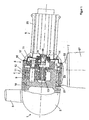
- the wind turbine shown includes a rotor 1 several rotor blades 3 held in a rotor hub 2
- Rotor 1 is a two-stage, from drive stage 4 and Output stage 5 existing planetary gear with one Generator 6 connected.
- the wind turbine is over a Azimuth bearing 7 placed on a tower 27 and is with the help of an azimuth drive 8 tracked the wind.
- the drive stage 4 of the planetary gear is as executes and contains double helical planetary gear after loading three or four planet gears 9 that are even are distributed around the circumference of a planet carrier 10.
- the bearings 11 of the planet gears 9 can optionally be used as Rolling bearings or slide bearings.
- the Planetary gears 9 mesh with a ring gear 12 and a sun gear 13 on. Planetary gears 9, ring gear 12 and sun gear 13 of the Drive stage 4 are with double helical teeth Mistake.
- the sun gear 13 of the drive stage 4 is with the Planet carrier 14 of the output stage 5 connected.
- This Connection is rotationally fixed, but can be moved longitudinally by one ensure even load distribution. So that too Output stage 5 has an optimal load distribution here the planet carrier 14 is mounted and is adjustable only held by the gearing forces.
- the shaft 18 of the sun gear 19 of the output stage 5 also forms the shaft 19 of the high-speed generator 6 is a unit.
- the ring gears 12, 16 of the drive stage 4 and the output stage 5 form a unit with the gear housing 20, the Ring gears 12, 16 are screwed in. It is also possible, the ring gears 12, 16 and the gear housing 20 from to manufacture the same workpiece.
- the rotor hub 2 is directly connected to the planet carrier 10 of the drive stage 4, for. B. connected by screwing.
- the planet carrier 10 is in two large roller bearings 21, the serve at the same time the storage of the rotor 1 in Gear housing 20 fixed.
- the planet carrier 10 transmits thus all of the rotor blades 3 attacking Wind forces into the gearbox 20.
- the gearbox 20 is in turn formed with a foot 22 so that it is directly on Azimuth bearings 7 are screwed and so the forces in the Tower 27 can transfer.
- the housing 23 of the generator 6 is flanged directly to the gear housing 20.
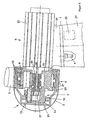
- the planetary gear is completely in the Rotor hub 2 placed.
- the gear housing 20 is with the Rotor hub 2 connected and thus takes the drive speed on.
- Both the two ring gears 12 of the double helical teeth Drive stage 4 as well as the single helical ring gear 16 the output stage 5 are in the rotating gear housing 20 placed and represent the coupling.
- the drive stage 4 is designed as a stationary gear, with its planet carrier 14 stands still and firmly with the housing 23 of the generator 6 connected is.
- the planet carrier 10 of the drive stage 4 takes also the two large roller bearings 21, which the Wear gear housing 20 and thus also rotor hub 2. about these two large rolling bearings 21 will be the total to which Rotor blades 3 attacking wind forces on the housing 23 of the Generator 6 transmitted.
- the housing 23 of the generator 6 itself is in turn formed with a foot 24 which is connected to the Azimuth bearing 7 is screwed so that the forces directly in the tower 27 of the wind turbine can be initiated.
- the Drive stage 4 between the generator 6 and the output stage 5 can be placed. So it is also necessary to use the shaft 18 of the sun gear 17 of the output stage 5 through the sun gear 13 to drive stage 4.
- the generator 6 can be oil-cooled for reasons of higher performance be, advantageously this oil circuit with the Oil circuit of the transmission is connected. To do that To keep the machine housing compact or completely closed dispense with the units such as lubrication system 26, Control cabinet and azimuth drive 8, in the upper area of the Tower 27 arranged.
Landscapes
- Engineering & Computer Science (AREA)
- General Engineering & Computer Science (AREA)
- Mechanical Engineering (AREA)
- Life Sciences & Earth Sciences (AREA)
- Sustainable Development (AREA)
- Sustainable Energy (AREA)
- Chemical & Material Sciences (AREA)
- Combustion & Propulsion (AREA)
- Wind Motors (AREA)
- Retarders (AREA)
- Connection Of Motors, Electrical Generators, Mechanical Devices, And The Like (AREA)
- Structures Of Non-Positive Displacement Pumps (AREA)
Abstract
Description
Die Erfindung betrifft ein Getriebe für eine Windkraftanlage
mit den Merkmalen des Oberbegriffes des Patentanspruches 1.The invention relates to a transmission for a wind turbine
with the features of the preamble of
Moderne Windkraftanlagen werden immer stärker von ökologischen und ökonomischen Zwängen beeinflußt. Die Ökonomie verlangt, daß moderne Windkraftanlagen mit herkömmlicher Energiegewinnung, z. B. durch fossile Kraftwerke oder Nuklearkraftwerke konkurrieren können. Das setzt Hochleistungsanlagen mit geringem Leistungsgewicht in kompakter Bauform voraus. Aus Belastungs- und Umweltgründen (Geräuschemission) sind die dynamischen Belastungen zu reduzieren. Die Aufstellungsorte sollten möglichst kontinuierliche und starke Windverhältnisse garantieren und dünn besiedelt sein. Eine Alternative bieten Offshore-Anlagen, die wiederum aufgrund der hohen Installationsaufwendungen noch leistungsfähigere, kompaktere und leichtere Anlagen verlangen.Modern wind turbines are becoming increasingly ecological and economic constraints. The economy demands that modern wind turbines with conventional Energy generation, e.g. B. by fossil power plants or Nuclear power plants can compete. That sets High performance systems with a low power to weight ratio compact design ahead. For pollution and environmental reasons (Noise emission) are the dynamic loads too to reduce. The locations should be as possible guarantee continuous and strong wind conditions and to be sparsely populated. Offshore systems offer an alternative, which in turn is still due to the high installation costs require more powerful, compact and lighter systems.
Der Antriebsstrang bekannter Windkraftanlagen (EP-OS 635 639) setzt sich zusammen aus dem Rotorblättern mit der Rotornabe, der Rotorwelle mit der Rotorlagerung, einem mehrstufigen Planeten-Stirnradgetriebe, einer Kupplung und einem Generator. Die Rotorblätter sind mit der Rotornabe verbunden und treiben die Rotorwelle an. Diese ist in einem großen Wälzlager aufgenommen, das über einen Maschinenrahmen mit dem Azimutlager verbunden ist. Auf diese Weise werden die am Rotor angreifenden Windkräfte in den Turm eingeleitet. Diese Lagerung erfordert einen Wellenabschnitt zwischen dem Rotor und dem Getriebe. Das zweite Rotorwellenlager wird von dem Getriebe gebildet, dessen Antriebshohlwelle über eine Schrumpfscheibe mit der Rotorwelle verbunden ist. Das Getriebe stützt sich über eine doppelarmige Drehmomentstütze ebenfalls an dem Maschinenrahmen ab. Diese bekannte Windkraftlanlage beansprucht verhältnismäßig viel Raum und ist dadurch in der Leistungsfähigkeit beschränkt.The drive train of known wind turbines (EP-OS 635 639) is made up of the rotor blades with the rotor hub, the rotor shaft with the rotor bearing, a multi-stage Planetary spur gear, a clutch and a generator. The rotor blades are connected to the rotor hub and drive the rotor shaft. This is in a large rolling bearing recorded that over a machine frame with the Azimuth bearing is connected. In this way, those on the rotor attacking wind forces introduced into the tower. This Storage requires a shaft section between the rotor and the transmission. The second rotor shaft bearing is from the Gearbox formed, the hollow drive shaft via a Shrink disc is connected to the rotor shaft. The gear is also supported by a double-arm torque arm on the machine frame. This well-known wind turbine takes up a lot of space and is therefore in the Performance limited.
Aus der EP-OS 811 764 ist eine Windkraftanlage bekannt, bei der der Rotor direkt an dem Planetenträger eines einstufigen Planetengetriebes angebaut ist. Dieses Getriebe und der Generator sind an einem gemeinsamen Maschinenrahmen montiert.A wind turbine is known from EP-OS 811 764, in which the rotor directly on the planet carrier of a one-stage Planetary gear is attached. This gear and the Generators are mounted on a common machine frame.
In der WO 96/11338 ist ein zweistufiges Planetengetriebe mit zwei einfach verzahnten Planetenstufen für eine Windkraftanlage beschrieben. Der Rotor ist direkt an dem Planetenträger angebaut und die Lagerung des Rotors erfolgt im Getriebegehäuse. Die weitere Anbindung des Getriebes an die Windkraftanlage ist nicht beschrieben.WO 96/11338 includes a two-stage planetary gear two single toothed planetary stages for a wind turbine described. The rotor is attached directly to the planet carrier and the rotor is mounted in the gearbox. The further connection of the transmission to the wind turbine is not described.
In der Veröffentlichung "Gears for Wind Power Plants" in Second International Symposium on Wind Energy Systems 1978, Seiten C6-89 bis C6-106 ist ein dreistufiges Planetengetriebe für eine Windkraftanlage beschrieben. Alle Planetenstufen dieses Planetengetriebes sind gleichartig ausgeführt und mit einer Doppelverzahnung versehen. Die Planetenstufen sind koaxial hintereinander angeordnet, wodurch das Planetengetriebe verhältnismäßig groß baut.In the publication "Gears for Wind Power Plants" in Second International Symposium on Wind Energy Systems 1978, pages C6-89 up to C6-106 is a three-stage planetary gear for one Wind turbine described. All planetary levels of this Planetary gear are of the same design and with one Provide double teeth. The planetary stages are coaxial arranged one behind the other, creating the planetary gear builds relatively large.
Der Erfindung liegt die Aufgabe zugrunde, ein Konzept für eine Windkraftanlage zu entwickeln, das kompakter baut und damit für höhere Leistungen in einem Bereich von etwa 2,5 - 5 MW bei nur geringfügig schwerer und aufwendigerer Bauweise geeignet ist.The invention has for its object a concept for a To develop wind turbines that are more compact and therefore for higher outputs in a range of around 2.5 - 5 MW at only slightly heavier and more complex construction is suitable.
Die zugrundeliegende Aufgabe wird bei einem gattungsgemäßen
Getriebe für eine Windkraftanlage erfindungsgemäß durch die
kennzeichnenden Merkmale des Anspruches 1 gelöst. Vorteilhafte
Ausgestaltungen der Erfindung sind Gegenstand der
Unteransprüche. The underlying task is in a generic
Gearbox for a wind turbine according to the invention by
characterizing features of
Durch die direkte Verbindung der Rotornabe mit der Antriebsstufe des zweistufigen Planetengetriebes wird eine kompakte Bauweise erreicht. Eine besonders kompakte Bauweise wird möglich, wenn die Rotornabe mit dem Getriebegehäuse verbunden wird, weil in diesem Fall das gesamte Getriebe in der Rotornabe untergebracht werden kann. Durch die Doppelschrägverzahnung der Antriebsstufe und die schrägverzahnten Stufenplaneten der Abtriebsstufe sind auf kleinerem Raum höhere Übersetzungen zu erzielen. Bei dem erfindungsgemäßen Getriebe kann weiterhin auf einen Maschinenrahmen verzichtet und das Gehäuse des Getriebes oder des Generators direkt mit dem Azimutlager verbunden werden.Through the direct connection of the rotor hub to the drive stage The two-stage planetary gear is a compact design reached. A particularly compact design is possible if the rotor hub is connected to the gear housing because in In this case, the entire gearbox is housed in the rotor hub can be. Due to the double helical toothing of the drive stage and the helical step planets are the output step achieve higher translations in a smaller space. In which Gearbox according to the invention can continue to a Machine frame dispensed with and the housing of the gearbox or of the generator can be connected directly to the azimuth bearing.
Zwei Ausführungsbeispiele der Erfindung sind in der Zeichnung
dargestellt und werden im folgenden näher erläutert. Es
zeigen:
Die dargestellte Windkraftanlage umfaßt einen Rotor 1 mit
mehreren in einer Rotornabe 2 gehaltenen Rotorblättern 3. Der
Rotor 1 ist über ein zweistufiges, aus Antriebsstufe 4 und
Abtriebsstufe 5 bestehendes Planetengetriebe mit einem
Generator 6 verbunden. Die Windkraftanlage ist über ein
Azimutlager 7 auf einen Turm 27 aufgesetzt und wird mit Hilfe
eines Azimutantriebes 8 dem Wind nachgeführt.The wind turbine shown includes a
Die Antriebsstufe 4 des Planetengetriebes ist als
doppelschrägverzahnte Planetenstufe ausführt und enthält je
nach Belastung drei oder vier Planetenräder 9, die gleichmäßig
am Umfang eines Planetenträgers 10 verteilt angeordnet sind.
Die Lager 11 der Planetenräder 9 können wahlweise als
Wälzlager oder als Gleitlager ausgebildet sein. Die
Planetenräder 9 greifen in ein Hohlrad 12 und ein Sonnenrad 13
ein. Planetenräder 9, Hohlrad 12 und Sonnenrad 13 der
Antriebsstufe 4 sind mit einer Doppelschrägverzahnung
versehen.The drive stage 4 of the planetary gear is as
executes and contains double helical planetary gear
after loading three or four
Das Sonnenrad 13 der Antriebsstufe 4 ist mit dem
Planetenträger 14 der Abtriebsstufe 5 verbunden. Diese
Verbindung ist drehfest, aber längsbeweglich, um eine
gleichmäßige Lastverteilung sicherzustellen. Damit auch die
Abtriebsstufe 5 eine optimale Lastverteilung aufweist, ist
hier der Planetenträger 14 einstellbeweglich gelagert und wird
lediglich von den Verzahnungskräften gehalten. The
In dem Planetenträger 14 der Abtriebsstufe 5 sind in Wälzoder
Gleitlagern mehrere Planetenräder 15 gelagert. Um höhere
Übersetzungen zu realisieren, sind diese Planetenräder 15 als
Stufenplaneten ausgebildet, wobei eine Stufe mit dem Hohlrad
16 und die andere Stufe mit dem Sonnenrad 17 der Abtriebsstufe
5 in Eingriff steht.In the
Die Welle 18 des Sonnenrades 19 der Abtriebsstufe 5 bildet mit
der Welle 19 des schnellaufenden Generators 6 eine Einheit.
Alternativ ist es möglich, die Verzahnung für das Sonnenrad 17
direkt in die Welle 19 des Generators 6 einzuschneiden oder
aber das Sonnenrad 17 als Steckritzel einzupressen.The
Die Hohlräder 12, 16 der Antriebsstufe 4 und der Abtriebsstufe
5 bilden mit dem Getriebegehäuse 20 eine Einheit, wobei die
Hohlräder 12, 16 eingeschraubt werden. Es ist aber auch
möglich, die Hohlräder 12, 16 und das Getriebegehäuse 20 aus
demselben Werkstück herzustellen.The
Gemäß Fig. 1 ist die Rotornabe 2 direkt mit dem Planetenträger
10 der Antriebsstufe 4, z. B. durch Verschrauben verbunden.
Der Planetenträger 10 ist in zwei großen Wälzlagern 21, die
gleichzeitig auch der Lagerung des Rotors 1 dienen, im
Getriebegehäuse 20 fixiert. Der Planetenträger 10 überträgt
somit die gesamten, an den Rotorblättern 3 angreifenden
Windkräfte in das Getriebegehäuse 20. Das Getriebegehäuse 20
wiederum ist mit einem Fuß 22 so ausgebildet, daß es direkt am
Azimutlager 7 angeschraubt werden und so die Kräfte in den
Turm 27 überleiten kann. Das Gehäuse 23 des Generators 6 ist
direkt an das Getriebegehäuse 20 angeflanscht.1, the
Gemäß Fig. 2 ist das Planetengetriebe komplett in der
Rotornabe 2 plaziert. Das Getriebegehäuse 20 ist mit der
Rotornabe 2 verbunden und nimmt somit die Antriebsdrehzahl
auf. Sowohl die beiden Hohlräder 12 der doppelschrägverzahnten
Antriebsstufe 4 als auch das einfachschrägverzahnte Hohlrad 16
der Abtriebsstufe 5 sind in dem sich drehenden Getriebegehäuse
20 plaziert und stellen die Koppelung dar. Die Antriebsstufe 4
ist als Standgetriebe ausgeführt, wobei deren Planetenträger
14 stillsteht und fest mit dem Gehäuse 23 des Generators 6
verbunden ist. Der Planetenträger 10 der Antriebsstufe 4 nimmt
auch die beiden großen Wälzlager 21 auf, die das
Getriebegehäuse 20 und damit auch die Rotornabe 2 tragen. Über
diese beiden großen Wälzlager 21 werden die gesamten, an den
Rotorblättern 3 angreifenden Windkräfte auf das Gehäuse 23 des
Generators 6 übertragen. Das Gehäuse 23 des Generators 6
selbst ist wiederum mit einem Fuß 24 ausgebildet, der an das
Azimutlager 7 angeschraubt wird, so daß die Kräfte direkt in
den Turm 27 der Windkraftanlage eingeleitet werden können.2, the planetary gear is completely in the
Um den Planetenträger 10 der Antriebsstufe 4 mit dem Gehäuse
23 des Generators 6 direkt verschrauben zu können, muß die
Antriebsstufe 4 zwischen dem Generator 6 und der Abtriebsstufe
5 plaziert werden. Somit ist es auch erforderlich, die Welle
18 des Sonnenrades 17 der Abtriebsstufe 5 durch das Sonnenrad
13 der Antriebsstufe 4 zu führen.Around the
Da bei dem Getriebe gemäß Fig. 2 das bei herkömmlichen
Windkraftanlagen genutzte freie Wellenende zwischen Getriebe
und Generator 6 zum Anbau einer Scheibenbremse nicht mehr
verfügbar ist, wird eine naßlaufende Bremse 25 in dem
Getriebegehäuse 20 installiert. Bei einer Betätigung der
Bremse 25 blockiert der Planetenträger 14 der Abtriebsstufe 5
drehfest mit dem Getriebegehäuse 20.Since in the transmission according to FIG. 2 that in conventional
Wind turbines used free shaft end between gear
and
Der Generator 6 kann aus Gründen höherer Leistung ölgekühlt
sein, wobei vorteilhafterweise dieser Ölkreislauf mit dem
Ölkreislauf des Getriebes verbunden wird. Um das
Maschinengehäuse kompakt zu halten bzw. darauf komplett zu
verzichten, werden die Aggregate wie Schmieranlage 26,
Schaltschrank und Azimutantrieb 8, im oberen Bereich des
Turmes 27 angeordnet.The
Claims (9)
- A gear for a wind power plant with a rotor (1) and a generator (6), whereby the gear is designed as a two-stage planetary gear with a driving stage (4) and a driven stage (5) and the driving stage (4) of the planetary gear is connected directly to the rotor (1) and is provided with a double helical gearing, characterised in that the driven stage (5) is designed with helical gear stage planets, in that the sun wheel (13) of the driving stage (4) is mounted torsionally stabil and adjustably mobile with the planet carrier (14) of the driven stage (5) and in that the planet carrier (14) of the driven stage (5) is designed adjustably mobile and is held only by the gearing forces.
- The gear as claimed in claim 1, characterised in that the planet carrier (10) of the driving stage (4) is mounted in the gear housing (20) via two rolling bearings (21), which at the same time act as support for the rotor (1).
- The gear as claimed in claim 1 or 2, characterised in that the sun wheel (17) of the driven stage (5) is connected directly to the shaft (19) of the generator (6).
- The gear as claimed in any one of claims 1 to 3, characterised in that the planet carrier (10) of the driving stage (4) is connected to the rotor hub (2) .
- The gear as claimed in claim 4, characterised in that the gear housing (20) is connected to the housing (23) of the generator (6) and is provided with a foot (22).
- The gear as claimed in any one of claims 1 to 3, characterised in that the gear housing (20) is connected to the rotor hub (2).
- The gear as claimed in claim 5, characterised in that the shaft (18) of the sun wheel (17) of the driven stage (5) is guided through the sun wheel (13) of the driving stage (4).
- The gear as claimed in claim 6 or 7, characterised in that the planet carrier (10) of the driving stage (4) is connected to the housing (23) of the generator (6).
- The gear as claimed in any one of claims 6 to 8, characterised in that a brake (25) is arranged in the gear housing (20).
Applications Claiming Priority (2)
| Application Number | Priority Date | Filing Date | Title |
|---|---|---|---|
| DE19916454 | 1999-04-12 | ||
| DE19916454A DE19916454A1 (en) | 1999-04-12 | 1999-04-12 | Gearbox for a wind turbine |
Publications (3)
| Publication Number | Publication Date |
|---|---|
| EP1045140A2 EP1045140A2 (en) | 2000-10-18 |
| EP1045140A3 EP1045140A3 (en) | 2002-08-14 |
| EP1045140B1 true EP1045140B1 (en) | 2004-09-22 |
Family
ID=7904272
Family Applications (1)
| Application Number | Title | Priority Date | Filing Date |
|---|---|---|---|
| EP00107377A Expired - Lifetime EP1045140B1 (en) | 1999-04-12 | 2000-04-05 | Gear box for a wind turbine |
Country Status (6)
| Country | Link |
|---|---|
| US (1) | US6459165B1 (en) |
| EP (1) | EP1045140B1 (en) |
| JP (1) | JP4119073B2 (en) |
| AT (1) | ATE277283T1 (en) |
| DE (2) | DE19916454A1 (en) |
| ES (1) | ES2226631T3 (en) |
Cited By (3)
| Publication number | Priority date | Publication date | Assignee | Title |
|---|---|---|---|---|
| WO2012128726A1 (en) | 2011-03-24 | 2012-09-27 | Gorazd Hlebanja | Gear box for a wind turbine |
| DE10302192B4 (en) * | 2003-01-20 | 2014-08-28 | Siemens Aktiengesellschaft | Planetary gear with a compensating coupling |
| EP3284976B1 (en) | 2016-08-19 | 2020-05-06 | Flender GmbH | Planet carrier |
Families Citing this family (86)
| Publication number | Priority date | Publication date | Assignee | Title |
|---|---|---|---|---|
| GB0002126D0 (en) * | 2000-01-31 | 2000-03-22 | Hanson Transmissions Internati | Planetary gear stage |
| GB0002122D0 (en) * | 2000-01-31 | 2000-03-22 | Hansen Transmissions Int | Gear unit |
| DE01954251T1 (en) * | 2000-08-15 | 2005-05-04 | Hansen Transmissions Int | Drive assembly for a wind turbine |
| DE10043593B4 (en) * | 2000-09-01 | 2014-01-09 | Renk Ag | Transmission for wind generators |
| DE10114609A1 (en) * | 2001-03-23 | 2002-09-26 | Enron Wind Gmbh | Torque transmission device for a wind turbine |
| DK174085B1 (en) * | 2001-04-02 | 2002-06-03 | Vestas Wind Sys As | Wind turbine with planetary gear |
| DE10119428A1 (en) * | 2001-04-20 | 2002-10-24 | Enron Wind Gmbh | Base frame for arranging the shaft of the rotor of a wind turbine on its tower |
| DE10119427A1 (en) | 2001-04-20 | 2002-10-24 | Enron Wind Gmbh | Coupling device for a wind turbine |
| GB2381047B (en) * | 2001-10-05 | 2005-05-25 | Hansen Transmissions Int | Modular Wind Turbine Drive Arrangement |
| US20040247437A1 (en) * | 2001-10-25 | 2004-12-09 | Ryoichi Otaki | Wind power generator |
| DE10159973A1 (en) | 2001-12-06 | 2003-06-18 | Winergy Ag | Gearbox for a wind turbine |
| DE10231948A1 (en) * | 2002-07-15 | 2004-01-29 | Ge Wind Energy Gmbh | Wind turbine and bearing arrangement therefor |
| DE10242707B3 (en) * | 2002-09-13 | 2004-04-15 | Aerodyn Engineering Gmbh | Wind turbine with concentric gear / generator arrangement |
| GB0226940D0 (en) * | 2002-11-19 | 2002-12-24 | Hansen Transmissions Int | Wind turbine gear unit with integrated rotor bearing |
| US7008348B2 (en) * | 2003-02-18 | 2006-03-07 | General Electric Company | Gearbox for wind turbine |
| GB0326951D0 (en) | 2003-11-20 | 2003-12-24 | Hansen Transmissions Int | Gear transmission unit wit planetary gears |
| DE102004004351B4 (en) * | 2004-01-29 | 2006-06-08 | Nordex Energy Gmbh | Planetary gearbox for a wind turbine |
| DE102004005543A1 (en) * | 2004-02-04 | 2005-09-01 | Siemens Ag | Wind turbine |
| FI117252B (en) * | 2004-07-15 | 2006-08-15 | Moventas Oy | Arrangement in planetary gear |
| JP4519635B2 (en) * | 2004-12-28 | 2010-08-04 | 三菱重工業株式会社 | Wind power generator |
| ES2274696B1 (en) * | 2005-06-13 | 2008-05-01 | GAMESA INNOVATION & TECHNOLOGY, S.L. | WIND TURBINE. |
| US8727921B2 (en) * | 2005-07-12 | 2014-05-20 | United Technologies Corporation | Belt-driven drive-train |
| ES2278530B1 (en) * | 2006-01-17 | 2008-07-01 | GAMESA INNOVATION & TECHNOLOGY, S.L. | WIND TURBINE WITH FULLY INTEGRATED MULTIPLIER. |
| BE1017135A3 (en) * | 2006-05-11 | 2008-03-04 | Hansen Transmissions Int | A GEARBOX FOR A WIND TURBINE. |
| ATE474158T1 (en) * | 2006-05-22 | 2010-07-15 | Vestas Wind Sys As | TRANSMISSION SYSTEM FOR A WIND TURBINE |
| DE102006057055B3 (en) * | 2006-12-04 | 2008-06-19 | Lohmann & Stolterfoht Gmbh | Power-split wind turbine gearbox |
| DE102007008758A1 (en) * | 2007-02-22 | 2008-08-28 | Schuler Pressen Gmbh & Co. Kg | Transmission hub unit for a wind turbine |
| WO2008104257A1 (en) * | 2007-02-27 | 2008-09-04 | Urs Giger | Wind power installation and transmission for same |
| DE102007012408A1 (en) * | 2007-03-15 | 2008-09-18 | Aerodyn Engineering Gmbh | Wind turbines with load-transmitting components |
| DE102007033806B4 (en) | 2007-07-17 | 2011-03-17 | Nordex Energy Gmbh | Transmission for a wind turbine |
| US7935020B2 (en) * | 2007-08-27 | 2011-05-03 | General Electric Company | Integrated medium-speed geared drive train |
| GB0719119D0 (en) * | 2007-10-01 | 2007-11-07 | Orbital 2 Ltd | A transmission system for power generation |
| US8198749B2 (en) * | 2007-10-23 | 2012-06-12 | Mitsubishi Heavy Industries, Ltd. | Wind turbine generator |
| AU2011226784B2 (en) * | 2007-10-23 | 2012-02-16 | Mitsubishi Heavy Industries, Ltd. | Wind power generator |
| WO2009080712A2 (en) * | 2007-12-21 | 2009-07-02 | Vestas Wind Systems A/S | A drive train for a wind turbine |
| US7985162B2 (en) * | 2008-03-19 | 2011-07-26 | Honeywell International Inc. | Signal torque module assembly for use in control moment gyroscope |
| US8075442B2 (en) * | 2008-09-05 | 2011-12-13 | General Electric Company | System and assembly for power transmission and generation in a wind turbine |
| US8096917B2 (en) * | 2008-11-13 | 2012-01-17 | General Electric Company | Planetary gearbox having multiple sun pinions |
| DE102008063868B3 (en) | 2008-12-19 | 2010-06-10 | Winergy Ag | Planetary gear for a wind turbine |
| DE102008063875A1 (en) * | 2008-12-19 | 2010-07-01 | Robert Bosch Gmbh | Generator arrangement for a wind turbine |
| DE102009008340A1 (en) | 2008-12-19 | 2010-06-24 | Robert Bosch Gmbh | Flow turbine |
| US7944077B2 (en) * | 2009-01-14 | 2011-05-17 | Amsc Windtec Gmbh | Generator, nacelle, and mounting method of a nacelle of a wind energy converter |
| US7815536B2 (en) * | 2009-01-16 | 2010-10-19 | General Electric Company | Compact geared drive train |
| DE102009016544A1 (en) * | 2009-04-06 | 2010-10-07 | Win 2 Verwaltungsgesellschaft Mbh | Wind energy plant, has head provided with crane cable guidance unit that is formed for hoisting and lowering drive train, where drive train comprises rotor blade, rotor hub, transmission and generator |
| EP2253843A1 (en) * | 2009-05-12 | 2010-11-24 | Ecotecnia Energias Renovables S.L. | Wind turbine |
| US8376708B2 (en) * | 2009-06-30 | 2013-02-19 | General Electric Company | Drivetrain system for a wind turbine generator and method of assembling the same |
| US8358029B2 (en) * | 2009-09-24 | 2013-01-22 | General Electric Company | Rotor-shaft integrated generator drive apparatus |
| BE1018974A3 (en) * | 2009-10-19 | 2011-12-06 | Hansen Transmissions Int | PLANETARY GEAR SYSTEM AND PLANET BEARER, RING WHEEL AND SUN WHEEL FOR USE IN SUCH PLANETARY GEAR SYSTEM. |
| DE102009052240A1 (en) | 2009-11-06 | 2011-05-12 | Fev Motorentechnik Gmbh | Turbine power plant i.e. wind turbine, has rotor and generator coupled together via drive train, where planetary gear is arranged in drive train between rotor and generator in front of transmission unit |
| WO2011058185A2 (en) | 2009-11-13 | 2011-05-19 | Suzlon Energy Gmbh | Drive unit for a wind turbine |
| DE102011105412A1 (en) | 2010-06-22 | 2011-12-22 | Skywind Gmbh | Coupling device for changing orientation of rotor shaft of rotor of turbine of wind turbine plant, has elastic element with spring and/or damping characteristics, where device supports turbine opposite to carrier and support device |
| DE102010031081A1 (en) | 2010-07-07 | 2012-01-12 | Skywind Gmbh | Wind turbine |
| US20110140440A1 (en) * | 2010-08-11 | 2011-06-16 | General Electric Company | Gearbox support system |
| US20110140441A1 (en) * | 2010-08-11 | 2011-06-16 | General Electric Company | Gearbox support system |
| WO2012029116A1 (en) * | 2010-08-31 | 2012-03-08 | 三菱重工業株式会社 | Planetary gear mechanism and wind-powered power generation device |
| US8038402B2 (en) * | 2010-09-28 | 2011-10-18 | General Electric Company | Compact geared drive train |
| ES2537715T3 (en) * | 2010-10-18 | 2015-06-11 | Vestas Wind Systems A/S | Wind turbine power transmission system |
| DE102010043435A1 (en) * | 2010-11-04 | 2012-05-10 | Aloys Wobben | Wind turbine |
| US20110143880A1 (en) * | 2010-12-01 | 2011-06-16 | General Electric Company | Drivetrain for generator in wind turbine |
| US8147183B2 (en) * | 2010-12-30 | 2012-04-03 | General Electric Company | Drivetrain for generator in wind turbine |
| CN102092637B (en) * | 2011-03-07 | 2013-03-27 | 南车株洲电力机车研究所有限公司 | Method for lifting gear boxes of wind generating set |
| WO2013010568A1 (en) * | 2011-07-15 | 2013-01-24 | Hansen Transmissions International Nv | Nacelle main frame structure and drive train assembly for a wind turbine |
| US8338980B2 (en) * | 2011-10-25 | 2012-12-25 | General Electric Company | Wind turbine with single-stage compact drive train |
| CN103089542A (en) * | 2011-10-28 | 2013-05-08 | 华锐风电科技(集团)股份有限公司 | Transmission system of wind generating set and wind generating set |
| CN102628428A (en) * | 2012-04-25 | 2012-08-08 | 东方电气集团东方汽轮机有限公司 | High power wind generating set |
| DK2657519T3 (en) * | 2012-04-26 | 2015-09-07 | Siemens Ag | Windmill |
| DE102012009362B4 (en) | 2012-05-10 | 2021-11-11 | Zf Friedrichshafen Ag | Optimized generator gear of a wind turbine |
| CN102729022B (en) * | 2012-06-15 | 2015-05-06 | 国电联合动力技术(连云港)有限公司 | Device and method for assembling transmission system of large-scale wind generating set |
| CN103883471B (en) * | 2012-12-20 | 2016-12-28 | 华锐风电科技(集团)股份有限公司 | Actuating device and wind power generating set |
| CN103042378B (en) * | 2013-01-07 | 2015-02-04 | 国电联合动力技术有限公司 | Tool and method for assembling transmission spindle and gearbox in wind turbine generator |
| US9097237B2 (en) | 2013-03-14 | 2015-08-04 | Broadwind Energy, Inc. | Tools and methods for uptower maintenance |
| US10378440B2 (en) | 2013-12-20 | 2019-08-13 | United Technologies Corporation | Geared turbofan with improved gear system maintainability |
| CN104481821A (en) * | 2014-10-09 | 2015-04-01 | 东方电气集团东方汽轮机有限公司 | Wind turbine generator and transmission structure thereof |
| EP3147538A1 (en) | 2015-09-23 | 2017-03-29 | Inovacor Ab | Compound planet gear arrangement and drive train arrangement |
| CN105545610B (en) * | 2016-03-11 | 2017-12-05 | 李勇强 | Total power speed-increasing type impeller and architecture system |
| DE102016111332B3 (en) * | 2016-06-21 | 2017-06-29 | Aerodyn Engineering Gmbh | Modular wind turbine |
| EP3379108B1 (en) | 2017-03-23 | 2021-06-30 | Cascade Drives AB | Compound planet gear arrangement and gear wheel arrangement |
| EP3379107B1 (en) | 2017-03-23 | 2020-11-25 | Cascade Drives AB | Compound planet gear arrangement and gear wheel arrangement |
| DK3379109T3 (en) | 2017-03-23 | 2021-08-30 | Cascade Drives Ab | COMBINED PLANET GEAR DEVICE AND GEAR DEVICE |
| EP3379106B1 (en) | 2017-03-23 | 2020-10-28 | Cascade Drives AB | Compound planet gear arrangement and gear wheel arrangement |
| WO2018172479A2 (en) | 2017-03-23 | 2018-09-27 | Cordrive Ab | Compound planet gear arrangement and gear wheel arrangement |
| CN110080953B (en) * | 2019-04-15 | 2021-10-15 | 国家电投集团科学技术研究院有限公司 | Wind power generation plant |
| CN110748612A (en) * | 2019-10-25 | 2020-02-04 | 三一重能有限公司 | Gear box and wind generating set |
| US11261848B2 (en) | 2020-01-31 | 2022-03-01 | Renew Energy Maintenance, Llc | Field machining of wind turbine gearboxes |
| DE102020108315A1 (en) | 2020-03-26 | 2021-09-30 | Voith Patent Gmbh | Gear arrangement for wind turbines |
| CN112943868B (en) * | 2021-01-28 | 2021-09-28 | 天津华建天恒传动有限责任公司 | High-power composite planetary wind power gear box |
Family Cites Families (19)
| Publication number | Priority date | Publication date | Assignee | Title |
|---|---|---|---|---|
| DE2618882C2 (en) * | 1976-04-29 | 1983-10-13 | Thyssen Industrie Ag, 4300 Essen | Planetary gear, especially for driving one of several rollers with a small center distance |
| US4239977A (en) * | 1978-09-27 | 1980-12-16 | Lisa Strutman | Surge-accepting accumulator transmission for windmills and the like |
| DE3005463A1 (en) * | 1980-02-14 | 1981-08-20 | Thyssen Industrie Ag, 4300 Essen | PLANETARY GEARBOX |
| DE3012069C2 (en) * | 1980-03-28 | 1982-05-06 | Messerschmitt-Bölkow-Blohm GmbH, 8000 München | Storage for the rotor of a wind turbine |
| US4331040A (en) * | 1980-04-21 | 1982-05-25 | Usm Corporation | Anti-backlash gearing |
| US4557666A (en) * | 1983-09-29 | 1985-12-10 | The Boeing Company | Wind turbine rotor |
| DE3625840A1 (en) * | 1986-07-30 | 1988-02-11 | Scholz Hans Ulrich | WIND TURBINE |
| DE3714859A1 (en) * | 1987-05-05 | 1988-11-24 | Walter Schopf | Combination gearing for small wind and water power plants |
| DE3741634A1 (en) * | 1987-12-09 | 1989-06-22 | Wittenstein Manfred | LOW-PLAYING SLOW TRANSLATING TWO-STAGE PLANETARY GEARBOX |
| US5222924A (en) * | 1990-01-31 | 1993-06-29 | Chan Shin | Over-drive gear device |
| IL106440A0 (en) * | 1993-07-21 | 1993-11-15 | Ashot Ashkelon Ind Ltd | Wind turbine transmission apparatus |
| KR960007401B1 (en) * | 1994-06-27 | 1996-05-31 | 신찬 | Multi-unit rotor blade system integrated wind turbine |
| EP0792415B2 (en) * | 1994-10-07 | 2007-08-29 | Windtec Consulting GmbH | Planetary gear for wind turbines |
| US5663600A (en) * | 1995-03-03 | 1997-09-02 | General Electric Company | Variable speed wind turbine with radially oriented gear drive |
| KR0163825B1 (en) * | 1995-03-27 | 1998-12-01 | 신찬 | Gearing device with a change input and normal speed output |
| US5679089A (en) * | 1995-09-14 | 1997-10-21 | The United States Of America As Represented By The Secretary Of The Navy | Bicoupled contrarotating epicyclic gears |
| DE29609794U1 (en) * | 1996-06-03 | 1996-08-22 | Aerodyn Gmbh | Gear-generator combination |
| FI108959B (en) * | 1998-06-18 | 2002-04-30 | Valmet Voimansiirto Oy | Planetary gear for a wind turbine |
| DE19916453A1 (en) * | 1999-04-12 | 2000-10-19 | Flender A F & Co | Wind turbine |
-
1999
- 1999-04-12 DE DE19916454A patent/DE19916454A1/en not_active Withdrawn
-
2000
- 2000-04-05 AT AT00107377T patent/ATE277283T1/en not_active IP Right Cessation
- 2000-04-05 DE DE50007835T patent/DE50007835D1/en not_active Expired - Lifetime
- 2000-04-05 EP EP00107377A patent/EP1045140B1/en not_active Expired - Lifetime
- 2000-04-05 ES ES00107377T patent/ES2226631T3/en not_active Expired - Lifetime
- 2000-04-11 US US09/547,011 patent/US6459165B1/en not_active Expired - Fee Related
- 2000-04-12 JP JP2000111423A patent/JP4119073B2/en not_active Expired - Fee Related
Cited By (3)
| Publication number | Priority date | Publication date | Assignee | Title |
|---|---|---|---|---|
| DE10302192B4 (en) * | 2003-01-20 | 2014-08-28 | Siemens Aktiengesellschaft | Planetary gear with a compensating coupling |
| WO2012128726A1 (en) | 2011-03-24 | 2012-09-27 | Gorazd Hlebanja | Gear box for a wind turbine |
| EP3284976B1 (en) | 2016-08-19 | 2020-05-06 | Flender GmbH | Planet carrier |
Also Published As
| Publication number | Publication date |
|---|---|
| DE50007835D1 (en) | 2004-10-28 |
| JP4119073B2 (en) | 2008-07-16 |
| DE19916454A1 (en) | 2000-10-19 |
| JP2000337246A (en) | 2000-12-05 |
| EP1045140A3 (en) | 2002-08-14 |
| US6459165B1 (en) | 2002-10-01 |
| ES2226631T3 (en) | 2005-04-01 |
| EP1045140A2 (en) | 2000-10-18 |
| ATE277283T1 (en) | 2004-10-15 |
Similar Documents
| Publication | Publication Date | Title |
|---|---|---|
| EP1045140B1 (en) | Gear box for a wind turbine | |
| EP1045139B1 (en) | Wind turbine | |
| EP1999369B1 (en) | Drive train between a rotor and a gear unit of a wind power plant | |
| DE10152712B4 (en) | Generator for a hydroelectric power plant | |
| EP1659286B1 (en) | Turning device for a wind generator power train | |
| DE102010043946A1 (en) | Drive unit for wind turbine | |
| EP1757839B1 (en) | Transmission for roller crusher | |
| EP2710259B1 (en) | Wind turbine gear mechanism | |
| DE102007047317A1 (en) | Decoupling of the drive shaft from the output shaft by a two-stage gearbox in a wind turbine | |
| DE10159973A1 (en) | Gearbox for a wind turbine | |
| DE19917608C1 (en) | Bowl mill gear | |
| DE10114609A1 (en) | Torque transmission device for a wind turbine | |
| WO2013072004A1 (en) | Epicyclic gearing with a gearing housing | |
| DE60202606T2 (en) | GAS TURBINE ARRANGEMENT | |
| DE19917609A1 (en) | Gearing for dish mill has bevel gearing via sun wheel driving planet wheel installed on shaft rotatably mounted in upper section of casing, and additional planet wheel axially offset on same shaft meshes with ring gear | |
| WO2011088925A2 (en) | Wind turbine having one or more rotor blades | |
| WO2010078886A2 (en) | Turbine power plant | |
| DE102008064244A1 (en) | Energy converter for use as drive strand in wind energy system to convert mechanical energy into electrical energy, has transmission unit with output shafts that mechanically stay in effective connection with rotors in generator | |
| WO2013104580A1 (en) | Wind turbine | |
| EP3767102A1 (en) | Drive train assembly | |
| DE102008019724A1 (en) | generator arrangement | |
| EP3599393A1 (en) | Crank drive for wind power plants and industrial applications | |
| DE102010010201A1 (en) | Transmission for use in wind power plant to drive generators to produce electrical current, has input shifted gear coupled to wind power rotor and arranged downstream to transmission-shifted gear i.e. planetary gear, attached to generator | |
| DD268741A1 (en) | WIND ENERGY CONVERTER FOR ENERGY SUPPLY SYSTEM | |
| DE102020108315A1 (en) | Gear arrangement for wind turbines |
Legal Events
| Date | Code | Title | Description |
|---|---|---|---|
| PUAI | Public reference made under article 153(3) epc to a published international application that has entered the european phase |
Free format text: ORIGINAL CODE: 0009012 |
|
| AK | Designated contracting states |
Kind code of ref document: A2 Designated state(s): AT BE CH CY DE DK ES FI FR GB GR IE IT LI LU MC NL PT SE |
|
| AX | Request for extension of the european patent |
Free format text: AL;LT;LV;MK;RO;SI |
|
| RAP1 | Party data changed (applicant data changed or rights of an application transferred) |
Owner name: A. FRIEDR. FLENDER GMBH |
|
| PUAL | Search report despatched |
Free format text: ORIGINAL CODE: 0009013 |
|
| RAP1 | Party data changed (applicant data changed or rights of an application transferred) |
Owner name: WINERGY AG |
|
| AK | Designated contracting states |
Kind code of ref document: A3 Designated state(s): AT BE CH CY DE DK ES FI FR GB GR IE IT LI LU MC NL PT SE |
|
| AX | Request for extension of the european patent |
Free format text: AL;LT;LV;MK;RO;SI |
|
| 17P | Request for examination filed |
Effective date: 20030131 |
|
| AKX | Designation fees paid |
Designated state(s): AT BE CH CY DE DK ES FI FR GB GR IE IT LI LU MC NL PT SE |
|
| 17Q | First examination report despatched |
Effective date: 20030718 |
|
| GRAP | Despatch of communication of intention to grant a patent |
Free format text: ORIGINAL CODE: EPIDOSNIGR1 |
|
| GRAS | Grant fee paid |
Free format text: ORIGINAL CODE: EPIDOSNIGR3 |
|
| GRAA | (expected) grant |
Free format text: ORIGINAL CODE: 0009210 |
|
| AK | Designated contracting states |
Kind code of ref document: B1 Designated state(s): AT BE CH CY DE DK ES FI FR GB GR IE IT LI LU MC NL PT SE |
|
| PG25 | Lapsed in a contracting state [announced via postgrant information from national office to epo] |
Ref country code: IT Free format text: LAPSE BECAUSE OF FAILURE TO SUBMIT A TRANSLATION OF THE DESCRIPTION OR TO PAY THE FEE WITHIN THE PRESCRIBED TIME-LIMIT;WARNING: LAPSES OF ITALIAN PATENTS WITH EFFECTIVE DATE BEFORE 2007 MAY HAVE OCCURRED AT ANY TIME BEFORE 2007. THE CORRECT EFFECTIVE DATE MAY BE DIFFERENT FROM THE ONE RECORDED. Effective date: 20040922 Ref country code: FR Free format text: LAPSE BECAUSE OF FAILURE TO SUBMIT A TRANSLATION OF THE DESCRIPTION OR TO PAY THE FEE WITHIN THE PRESCRIBED TIME-LIMIT Effective date: 20040922 Ref country code: IE Free format text: LAPSE BECAUSE OF FAILURE TO SUBMIT A TRANSLATION OF THE DESCRIPTION OR TO PAY THE FEE WITHIN THE PRESCRIBED TIME-LIMIT Effective date: 20040922 Ref country code: NL Free format text: LAPSE BECAUSE OF FAILURE TO SUBMIT A TRANSLATION OF THE DESCRIPTION OR TO PAY THE FEE WITHIN THE PRESCRIBED TIME-LIMIT Effective date: 20040922 Ref country code: GB Free format text: LAPSE BECAUSE OF FAILURE TO SUBMIT A TRANSLATION OF THE DESCRIPTION OR TO PAY THE FEE WITHIN THE PRESCRIBED TIME-LIMIT Effective date: 20040922 |
|
| REG | Reference to a national code |
Ref country code: GB Ref legal event code: FG4D Free format text: NOT ENGLISH |
|
| REG | Reference to a national code |
Ref country code: CH Ref legal event code: EP |
|
| REG | Reference to a national code |
Ref country code: IE Ref legal event code: FG4D Free format text: GERMAN |
|
| REF | Corresponds to: |
Ref document number: 50007835 Country of ref document: DE Date of ref document: 20041028 Kind code of ref document: P |
|
| PG25 | Lapsed in a contracting state [announced via postgrant information from national office to epo] |
Ref country code: GR Free format text: LAPSE BECAUSE OF FAILURE TO SUBMIT A TRANSLATION OF THE DESCRIPTION OR TO PAY THE FEE WITHIN THE PRESCRIBED TIME-LIMIT Effective date: 20041222 Ref country code: SE Free format text: LAPSE BECAUSE OF FAILURE TO SUBMIT A TRANSLATION OF THE DESCRIPTION OR TO PAY THE FEE WITHIN THE PRESCRIBED TIME-LIMIT Effective date: 20041222 Ref country code: DK Free format text: LAPSE BECAUSE OF FAILURE TO SUBMIT A TRANSLATION OF THE DESCRIPTION OR TO PAY THE FEE WITHIN THE PRESCRIBED TIME-LIMIT Effective date: 20041222 |
|
| NLV1 | Nl: lapsed or annulled due to failure to fulfill the requirements of art. 29p and 29m of the patents act | ||
| REG | Reference to a national code |
Ref country code: ES Ref legal event code: FG2A Ref document number: 2226631 Country of ref document: ES Kind code of ref document: T3 |
|
| PG25 | Lapsed in a contracting state [announced via postgrant information from national office to epo] |
Ref country code: AT Free format text: LAPSE BECAUSE OF NON-PAYMENT OF DUE FEES Effective date: 20050405 Ref country code: CY Free format text: LAPSE BECAUSE OF FAILURE TO SUBMIT A TRANSLATION OF THE DESCRIPTION OR TO PAY THE FEE WITHIN THE PRESCRIBED TIME-LIMIT Effective date: 20050405 Ref country code: LU Free format text: LAPSE BECAUSE OF NON-PAYMENT OF DUE FEES Effective date: 20050405 |
|
| GBV | Gb: ep patent (uk) treated as always having been void in accordance with gb section 77(7)/1977 [no translation filed] |
Effective date: 20040922 |
|
| REG | Reference to a national code |
Ref country code: IE Ref legal event code: FD4D |
|
| PG25 | Lapsed in a contracting state [announced via postgrant information from national office to epo] |
Ref country code: MC Free format text: LAPSE BECAUSE OF NON-PAYMENT OF DUE FEES Effective date: 20050430 |
|
| PLBE | No opposition filed within time limit |
Free format text: ORIGINAL CODE: 0009261 |
|
| STAA | Information on the status of an ep patent application or granted ep patent |
Free format text: STATUS: NO OPPOSITION FILED WITHIN TIME LIMIT |
|
| 26N | No opposition filed |
Effective date: 20050623 |
|
| EN | Fr: translation not filed | ||
| PG25 | Lapsed in a contracting state [announced via postgrant information from national office to epo] |
Ref country code: PT Free format text: LAPSE BECAUSE OF NON-PAYMENT OF DUE FEES Effective date: 20050222 |
|
| PGFP | Annual fee paid to national office [announced via postgrant information from national office to epo] |
Ref country code: ES Payment date: 20110526 Year of fee payment: 12 |
|
| PGFP | Annual fee paid to national office [announced via postgrant information from national office to epo] |
Ref country code: BE Payment date: 20110511 Year of fee payment: 12 Ref country code: FI Payment date: 20110414 Year of fee payment: 12 |
|
| PGFP | Annual fee paid to national office [announced via postgrant information from national office to epo] |
Ref country code: CH Payment date: 20110711 Year of fee payment: 12 |
|
| PGFP | Annual fee paid to national office [announced via postgrant information from national office to epo] |
Ref country code: DE Payment date: 20110620 Year of fee payment: 12 |
|
| BERE | Be: lapsed |
Owner name: *WINERGY A.G. Effective date: 20120430 |
|
| REG | Reference to a national code |
Ref country code: CH Ref legal event code: PL |
|
| PG25 | Lapsed in a contracting state [announced via postgrant information from national office to epo] |
Ref country code: CH Free format text: LAPSE BECAUSE OF NON-PAYMENT OF DUE FEES Effective date: 20120430 Ref country code: BE Free format text: LAPSE BECAUSE OF NON-PAYMENT OF DUE FEES Effective date: 20120430 Ref country code: FI Free format text: LAPSE BECAUSE OF NON-PAYMENT OF DUE FEES Effective date: 20120405 Ref country code: LI Free format text: LAPSE BECAUSE OF NON-PAYMENT OF DUE FEES Effective date: 20120430 |
|
| REG | Reference to a national code |
Ref country code: DE Ref legal event code: R119 Ref document number: 50007835 Country of ref document: DE Effective date: 20121101 |
|
| REG | Reference to a national code |
Ref country code: ES Ref legal event code: FD2A Effective date: 20130716 |
|
| PG25 | Lapsed in a contracting state [announced via postgrant information from national office to epo] |
Ref country code: ES Free format text: LAPSE BECAUSE OF NON-PAYMENT OF DUE FEES Effective date: 20120406 |
|
| PG25 | Lapsed in a contracting state [announced via postgrant information from national office to epo] |
Ref country code: DE Free format text: LAPSE BECAUSE OF NON-PAYMENT OF DUE FEES Effective date: 20121101 |