EP1044816A2 - Druckersteuerung auf Basis der Ausrichtung der Köpfe - Google Patents
Druckersteuerung auf Basis der Ausrichtung der Köpfe Download PDFInfo
- Publication number
- EP1044816A2 EP1044816A2 EP00303167A EP00303167A EP1044816A2 EP 1044816 A2 EP1044816 A2 EP 1044816A2 EP 00303167 A EP00303167 A EP 00303167A EP 00303167 A EP00303167 A EP 00303167A EP 1044816 A2 EP1044816 A2 EP 1044816A2
- Authority
- EP
- European Patent Office
- Prior art keywords
- printing process
- print heads
- printing
- recording medium
- Prior art date
- Legal status (The legal status is an assumption and is not a legal conclusion. Google has not performed a legal analysis and makes no representation as to the accuracy of the status listed.)
- Granted
Links
Images


Classifications
-
- B—PERFORMING OPERATIONS; TRANSPORTING
- B41—PRINTING; LINING MACHINES; TYPEWRITERS; STAMPS
- B41J—TYPEWRITERS; SELECTIVE PRINTING MECHANISMS, i.e. MECHANISMS PRINTING OTHERWISE THAN FROM A FORME; CORRECTION OF TYPOGRAPHICAL ERRORS
- B41J2/00—Typewriters or selective printing mechanisms characterised by the printing or marking process for which they are designed
- B41J2/005—Typewriters or selective printing mechanisms characterised by the printing or marking process for which they are designed characterised by bringing liquid or particles selectively into contact with a printing material
- B41J2/01—Ink jet
- B41J2/21—Ink jet for multi-colour printing
- B41J2/2132—Print quality control characterised by dot disposition, e.g. for reducing white stripes or banding
- B41J2/2135—Alignment of dots
Definitions
- the present invention relates to a printing system for controlling a printer having multiple print heads for the printing of an image on a recording medium based upon the alignment condition of the print heads. More specifically, the present invention concerns a printing system in which it is determined whether the print heads are effectively aligned and in which one of multiple different printing schemes is selected based upon the alignment determination.
- a conventional multiple print head printer typically prints an image on a recording medium in response to commands and data received from a printer driver that is executed within a computer attached to the printer.
- the conventional printer prints the image on the recording medium by moving the print heads in lateral scans across the recording medium while the print heads print an image corresponding to the print data received from the printer driver.
- the manner in which the printer driver directs the print heads to scan the recording medium for printing depends upon several factors including the type of image being printed, the desired resolution, and the type of recording medium being used. For example, the printer driver may command the printer to print an image by scanning over the same scan line of the recording medium several times in succession in order to improve the image quality.
- the printer may be commanded by the printer driver to print the current scan line in one direction and then to print the next scan line in the other direction.
- Print head speed and print head nozzle selection can also be varied to achieve the desired printed image.
- Various combinations of the aforementioned printer control operations may be used to achieve the desired image quality according to the print modes and conditions related to a given print request.
- some conventional printers provide an alignment process whereby the printer driver and the printer operate in a coordinated fashion to determine the degree of misalignment of the print heads, and to align the print heads if necessary.
- the alignment process is generally performed whenever it is determined that the print heads may be misaligned, because: (1) the user changed one or more ink cartridges in the printer; (2) a specified amount of time or number of print jobs has elapsed since the last time the alignment process was performed, (3) the printer detects that the print heads are misaligned, or (4) the user spontaneously chooses to perform the alignment process.
- the printer driver determines that the print heads may be misaligned for reasons discussed above, among others, the printer driver notifies the user of the problem by a dialog box on the computer display.
- This dialog box is generally displayed when the user attempts to send a print request to the printer from an application being executed in the computer. If the user chooses to initiate the alignment process, it is presumed by the printer driver that the alignment process has aligned the print heads sufficiently upon completion.
- printer drivers have either: (1) allowed the user to attempt to print the image in the normal fashion, thereby risking a reduction in quality of the printed image; or (2) prevented the user from proceeding with the print request until the alignment process is performed.
- This arrangement is unsatisfactory because a print request that is processed by a printer with misaligned print heads may have reduced image quality and because a user may desire to send a print request to the printer without taking the time to perform the alignment process.
- What is needed is a printer that can determine whether the print heads are effectively aligned and that can allow the user to obtain the best image quality possible when the printer driver determines that the print heads may be misaligned.
- the present invention addresses the foregoing by providing a printing system whereby one of multiple different printing schemes is selected based upon a determination that the print heads are not effectively aligned, thereby maintaining image quality and resolution. As a result, the user is allowed to print a quality image after being prompted to perform the alignment process and deciding not to do so.
- the present invention relates to a printer driver for execution within a computer attached to a printer having multiple heads whereby the printer driver determines whether the print heads may be misaligned because: (1) the user changed one or more ink cartridges in the printer; (2) a specified amount of time or number of print jobs has elapsed since the last time the alignment process was performed, or (3) the printer detects that the print heads are misaligned.
- the printer driver When the user attempts to initiate a print request, the printer driver generates a dialog box on the computer display prompting the user to perform the alignment process.
- the printer driver instructs the printer to print the requested image by using only one of the print heads, thereby reducing the adverse effects caused by misalignment of the print heads with respect to each other. For example, if the printer contains two of the same type of print heads, then the first one is chosen for printing when the print heads are misaligned. If, however, the print heads are a combination of a color ink print head and a black ink print head, then the color ink print head is used for printing when the print heads are misaligned, unless the image to be printed requires only black ink in which case the black ink print head is used. In this manner, the printer avoids image overlap and blurring that is caused by printing with two print heads that are misaligned with respect to each other.
- the printer driver instructs the printer to print the requested image by laterally scanning the print heads in one direction only when the user has chosen to perform the alignment process after being prompted to do so.
- the image quality is improved when printing without alignment because unilateral scanning of the print heads results in a higher quality printed image than bi-directional printing when the print heads are misaligned with respect to their properly aligned positions within the printer, respectively.
- the printer driver only one print head is utilized for scanning the recording medium in a single direction when printing without alignment, however, the other print control parameters provided to the printer by the printer driver generally remains the same. For example, a print request for printing a high resolution image on plain paper when the print heads are aligned would require the printer to scan both print heads in both directions, and to repeat the printing of each scan line twice. If the same print request is made when the print heads are misaligned, however, the printer would scan only print head number one in one direction only, but would still repeat the printing of each scan line twice.
- a print request is denied by the printer driver in the event that the requested print mode cannot be supported with only one print head when printing without alignment. For example, if the user initiates a print request for a photo-quality image and is then prompted by the printer driver to perform the alignment process, the print request will be cancelled by the printer driver if the user elects to forego the alignment process. This is because the printing of a photo-quality image requires the use of both print heads and therefore cannot be printed without alignment wherein only one print head is utilized.
- the user is allowed to proceed with a print request when the print heads may be in a misaligned state and the printer driver selects a printing scheme in such a situation whereby only one print head is utilized for scanning the recording medium in one direction only.
- This scheme results in improved quality of the printed image when the print heads are misaligned with respect to each other or with respect to the printer.
- Figure 1 shows a perspective view of computing equipment used in connection with the printer of the present invention.
- Figure 2 is a front perspective view of the printer shown in Figure 1.
- Figure 3 is a back perspective view of the printer shown in Figure 1.
- Figure 4 is a back, cut-away perspective view of the printer shown in Figure 1.
- Figure 5 is a front, cut-away perspective view of the printer shown in Figure 1.
- Figure 5A is a top-down plan view of the printer shown in Figure 1.
- Figure 5B shows a face-on view of clutch plate and gears operated by both line feed motor and carriage motor of the printer shown in Figure 1.
- Figure 5C is a flow diagram which depicts operation of the automatic sheet feeder process for the printer of an embodiment of the present invention.
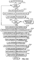
- Figure 5D is a flow diagram which depicts operation of the capping and purge process for the printer of an embodiment of the present invention.
- Figure 6 shows an example of a disposable ink cartridge used with an embodiment of the present invention.
- Figure 7 shows a face-on view of head configurations for print heads used with an embodiment of the present invention.
- Figure 8 is a block diagram showing the hardware configuration of a host processor interfaced to the printer of an embodiment of the present invention.
- Figure 9 shows a functional block diagram of the host processor and printer shown in Figure 8.
- Figure 10 is a block diagram showing the internal configuration of the gate array shown in Figure 8.
- Figure 11 shows the memory architecture of the printer of an embodiment of the present invention.
- Figure 12 shows an overall system flowchart detailing the operation of the printer of an embodiment of the present invention.
- Figure 13 is a flowchart showing print control flow in accordance with an embodiment of the present invention.
- Figure 14 depicts a table showing command flow during a printing sequence.
- Figure 15 is a flow diagram which depicts a hard power-on sequence for the printer of an embodiment of the present invention.
- Figure 16 is a flow diagram which depicts a soft power-on sequence for the printer of an embodiment of the present invention.
- Figure 17 is a flow diagram which depicts a soft power-off sequence for the printer of an embodiment of the present invention.
- Figure 21B is a continuation of the automatic sheet feed sequence shown in the automatic sheet feed sequence of Figure 21A.
- Figure 26 is a flow diagram which depicts line feed speed override logic of an embodiment of the present invention.
- Figure 28 is a representative view for explaining movement of print heads according to an embodiment of the invention.
- Figure 30 is a flowchart for describing a PRINT command issued by a printer driver according to an embodiment of the invention.
- Figure 35 is a flowchart for describing an AT_DELAY (automatic delay) command issued by a printer driver according to an embodiment of the invention.
- Figure 37 is a flowchart for describing a first carriage scan control called by the carriage task of Figure 36.
- Figure 41 is a flowchart for describing a carriage interrupt process performed by a printer control according to an embodiment of the invention.
- Figure 44 is a series of print mode tables for printing with alignment and without alignment pursuant to the printer driver software alignment process of Figure 43.
- Figure 45 is a flow diagram of processor-executable process steps to print color data.
- Figure 51 is a flowchart for describing prefire control timing according to an embodiment of the invention.
- Figure 52 is a flowchart for describing an update of prefire timers by a printer controller according to an embodiment of the invention.
- Figure 54 is a flowchart for describing generation of a nozzle-number-change prefire request by a printer driver according to an embodiment of the invention.
- Figure 55 is a flowchart for describing scan prefire processing by a printer controller according to an embodiment of the invention.
- Figure 56 is a flowchart for describing a prefire (print) function according to an embodiment of the invention.
- Figure 61 is a flowchart for describing use of a real-time environmental temperature for determination of driving times.
- Figure 63 is a diagram for describing heat pulse width modulation according to the invention in which a heat pulse width is maximized after a first time interval since a previous prefire operation.
- Figure 64 is a flowchart for describing heat pulse width modulation according to the invention in which a heat pulse width is maximized after a first time interval since a previous prefire operation.
- Figure 67 is a functional block diagram showing computing equipment communicating with the printer.
- Figure 68 is a flow diagram illustrating how print driver obtains status from printer and modifies processing of print data generation.
- Figure 70 illustrates process steps for bleed reduction.
- Figure 72 illustrates values stored in Color Table 1 as opposed to values stored in Color Table 2.
- Figure 74 is a flow diagram illustrating how the print driver sets the value for the smear timer.
- Figure 80 is a flow diagram for explaining how the print driver modifies its own operation based on status of the printer.
- Figure 82 illustrates modification of print driver operations.
- This section describes the mechanical layout and functionality of a printer which includes embodiments of the inventions described herein.
- FIG. 1 is a view showing the outward appearance of computing equipment used in connection with the embodiments of the invention described herein.
- Computing equipment 1 includes host processor 2.
- Host processor 2 comprises a personal computer (hereinafter "PC"), preferably an IBM PC-compatible computer having a windowing environment, such as Microsoft® Windows95.
- display 4 comprising a color monitor or the like
- keyboard 5 for entering text data and user commands
- pointing device 6 preferably comprises a mouse for pointing and for manipulating objects displayed on display 4.
- Computing equipment 1 includes a computer-readable memory medium, such as fixed computer disk 8, and floppy disk interface 9.
- Floppy disk interface 9 provides a means whereby computing equipment 1 can access information, such as data, application programs, etc., stored on floppy disks.
- a similar CD-ROM interface (not shown) may be provided with computing equipment 1, through which computing equipment 1 can access information stored on CD-ROMs.
- Disk 8 stores, among other things, application programs by which host processor 2 generates files, manipulates and stores those files on disk 8, presents data in those files to an operator via display 4, and prints data in those files via printer 10.
- Disk 8 also stores an operating system which, as noted above, is preferably a windowing operating system such as Windows95.
- Device drivers are also stored in disk 8. At least one of the device drivers comprises a printer driver which provides a software interface to firmware in printer 10. Data exchange between host processor 2 and printer 10 is described in more detail below.
- printer 10 is a multi-head serial printer. Accordingly, although the inventions described herein are not limited to use with such a printer, the inventions will be described in the context of a such a printer.
- Figures 2 and 3 show close-up perspective front and back views, respectively, of printer 10.
- the preferred embodiment of printer 10 is similar to the printer disclosed in U.S. Patent Application No. 08/972,113, entitled “Multi-Head Printing With Differing Resolutions", filed on November 17, 1997, which is incorporated herein by reference.
- printer 10 includes housing 11, access door 12, automatic feeder 14, automatic feed adjuster 16, manual feeder 17, manual feed adjuster 19, media eject port 20, ejection tray 21, tray receptacle 22, indicator light 23, power button 24, resume button 26, power supply 27, power cord 29, and parallel port connector 30.
- Housing 11 is approximately 498 mm in width by 271 mm in depth by 219 mm in height, and houses the internal workings of printer 10, including the print engine described below which prints images onto recording media. Included on housing 11 is access door 12. Access door 12 is manually openable and closeable so as to permit a user to access the internal workings of printer 10 and, in particular, to access print cartridges installed in printer 10 so as to allow the user to change or replace print cartridges.
- a front panel Disposed on the top of access door 12 is a front panel comprising indicator light 23, power button 24, and resume button 26.
- Power button 24 is a control by which a user can turn printer 10 on and off. Additional functions, however, are also available through power button 24. For example, a test print function can be selected by holding down power button 24 until a speaker (not shown) in printer 10 emits a sound, such as one beep. In response to this test print function, printer 10 prints a test pattern.
- Resume button 26 provides control by which an operator can resume printing after an error condition has occurred.
- resume button 26 can be used to activate other functions. For example, a print head cleaning function can be activated by holding down resume button 26 until the speaker in printer 10 produces a beep.
- printer 10 is able to provide a variety of consecutive beeping sounds. Each of these sounds indicates a different type of error, such as paper empty, paper jam, etc.
- Indicator light 23 is comprised of a single light pipe, a green light emitting diode (hereinafter "LED"), and an orange LED. Indicator light 23 provides a user with an indication of the operational state of printer 10. Specifically, when indicator light 23 is off, this indicates that printer 10 is powered off. When indicator light 23 is illuminated green (i.e., the green LED is activated), this indicates that printer 10 is powered on and is ready for printing. When indicator light 23 is green and blinking, this indicates an operational state of the printer, such as that the printer is currently powering on.
- LED green light emitting diode
- Indicator light 23 can also be illuminated orange by the orange LED. When indicator light 23 is illuminated orange, this indicates that a recoverable error, i.e., an operator call error, has occurred in printer 10. Recoverable errors comprise paper empty, paper jam, defective cartridge installed in printer 10, cartridge replacement in process, etc. It is possible to distinguish the type of recoverable error based on a number of beeps from printer 10's speaker. By counting these beeps when indicator LED is continuously orange, a user can determine which error has occurred and act accordingly.
- a recoverable error i.e., an operator call error
- indicator light 23 is orange and blinking, this indicates that a fatal error, i.e., a service call error, has occurred in printer 10. It is possible to distinguish the type of fatal error that has occurred merely by counting how many times the orange light has blinked.
- automatic feeder 14 is also included on housing 11 of printer 10.
- Automatic feeder 14 defines a media feed portion of printer 10. That is, automatic feeder 14 stores recording media onto which printer 10 prints images.
- printer 10 is able to print images on a variety of types of recording media. These types include, but are not limited to, plain paper, high resolution paper, transparencies, glossy paper, glossy film, back print film, fabric sheets, T-shirt transfers, bubble jet paper, greeting cards, brochure paper, banner paper, thick paper, etc.
- Automatic feeder 14 is able to accommodate a recording media stack which is approximately 13 mm thick. This means that automatic feeder 14 can hold, e.g., approximately 130 sheets of paper having a density of 64 g/m 2 or approximately 15 envelopes.
- individual sheets which are stacked within automatic feeder 14 are fed from automatic feeder 14 through printer 10. Specifically, rollers (described below) in printer 10 draw individual media from automatic feeder 14 into printer 10. These individual media are then fed in a "J" type path through the rollers to eject port 20 shown in Figure 2.
- Automatic feeder 14 includes automatic feed adjuster 16.
- Automatic feed adjuster 16 is laterally movable to accommodate different media sizes within automatic feeder 14.
- Automatic feeder 14 also includes backing 31, which is extendible to support recording media held in automatic feeder 14. When not in use, backing 31 is stored within a slot in automatic feeder 14, as shown in Figure 2.
- manual feeder 17 shown in Figure 3, which also defines a media feed portion of printer 10.
- manual feeder 17 can accommodate media having a density of at least between 64 g/m 2 and 550 g/m 2 , and having a thickness of 0.8 mm. Sheets fed through manual feeder 17 are fed straight through the rollers in printer 10 to eject port 20.
- manual feeder 17 includes manual feed adjuster 19. By sliding manual feed adjuster 19 laterally, a user can vary the media which manual feeder 17 can accommodate.
- printer 10 can print images on media having a variety of different sizes. These sizes include, but are not limited to, letter, legal, A4, A3, A5, B4, B5, tabloid, #10 envelope, DL envelope, banner, wide banner, and LTR full bleed. Custom-sized recording media can also be used with printer 10.
- Ejection tray 21 includes spring-biased flaps which support media ejected from printer 10, and which move downwardly as more media are piled thereon. When not in use, ejection tray 21 is stored within tray receptacle 22 of printer 10, as shown in Figure 2.
- Power cord 29 connects printer 10 to an external AC power source.
- Power supply 27 is used to convert AC power from the external power source, and to supply the converted power to printer 10.
- Parallel port 30 connects printer 10 to host processor 2.
- Parallel port 30 preferably comprises an IEEE-1284 bi-directional port, over which data and commands, such as those described below in section 3.0, are transmitted between printer 10 and host processor 2.
- FIGs 4 and 5 show back and front cut-away perspective views, respectively, of printer 10.
- printer 10 includes rollers 32, noted above, for transporting media from either automatic feeder 14 or manual feeder 17 through printer 10 to media eject port 20. Rollers 32 rotate in a counterclockwise direction during media transport, as indicated by arrow 32a shown in Figure 4.
- Line feed motor 34 controls the rotation of rollers 32.
- the arrangement shown in Figure 4 for depicting the operational relationship between line feed motor 34 and rollers 32 is a simplified arrangement for purposes of the present discussion. A more detailed description of this relationship can be found in Figures 5A and 5B and in the corresponding descriptions for these figures presented below.
- Line feed motor 34 preferably comprises a 96-step, 2 phase pulse motor and is controlled in response to signal commands received from circuit board 35.
- Line feed motor 34 is driven by a motor driver having four-level current control, with the four levels preferably set at 0, 40, 70 and 100 percent of maximum current.
- line feed motor 34 is able to cause rollers 32 to rotate so that a recording medium is fed through printer 10 at 238 mm/sec at the maximum speed of line feed motor 34.
- line feed resolution is (1/720)inches/pulse (2-2 phase)
- line resolution is (1/1440)inches/pulse (1-2 phase). Print modes are described in more detail below.
- printer 10 is a dual-cartridge printer which prints images using two print heads (i.e., one head per cartridge). Specifically, these cartridges preferably are held side-by-side by cartridge receptacles 37a and 37b such that respective print heads on the cartridges are offset horizontally from each other.
- Carriage motor 39 shown in Figure 4, controls the motion of cartridge receptacles 37a and 37b in response to signal commands received from circuit board 35. Specifically, carriage motor 39 controls the motion of belt 40, which in turn controls the movement of cartridge receptacles 37a and 37b along carriage 41. In this regard, carriage motor 39 provides for bi-directional motion of belt 40, and thus of cartridge receptacles 37a and 37b. By virtue of this feature, printer 10 is able to print images from both left to right and right to left.
- Carriage motor 39 comprises a 96-step, 2 phase pulse motor resulting in a carriage resolution of (9/360)inches/pulse.
- Carriage motor 39 is driven by a motor driver having four-level current control.
- carriage motor 39 When printer 10 is printing in a 360 dpi standard default mode, carriage motor 39 is driven to cause cartridge receptacles 37a and 37b to move along carriage 41 at a speed of 22.5 inches/sec, which corresponds to a print head heat pulse frequency of 6.51 KHz.
- carriage motor 39 is driven to cause cartridge receptacles 37a and 37b to move along carriage 41 at a speed of 27.5 inches/sec, which corresponds to a print head heat pulse frequency of 10.0 KHz.
- carriage motor 39 In contrast, when printer 10 is printing in a 720 dpi mode, carriage motor 39 is driven to cause cartridge receptacles 37a and 37b to move along carriage 41 at a default speed of 13.8 inches/sec (10.0 KHz).
- Cartridge receptacles 37a and 37b are used to hold ink cartridges 43a and 43b (which each include a print head and can include one or more removable ink reservoirs for storing ink) in printer 10.
- ink cartridges 43a and 43b which each include a print head and can include one or more removable ink reservoirs for storing ink
- a representative ink cartridge is described below in Section 1.3 with reference to Figure 6.
- printer 10 preferably includes pre-fire receptacles 42a and 42b, wipers 44a and 44b and ink cleaning mechanism 45.
- Ink cleaning mechanism 45 is disposed at home location 46 and comprises a rotary pump (not shown) and print head connection caps 47a and 47b.
- Print head connection caps 47a and 47b connect to print heads of cartridges installed in cartridge receptacles 37a and 37b, respectively, during print head cleaning and at other times, such as when printer 10 is powered off, so as to protect the print heads.
- Line feed motor 34 drives the rotary pump of ink cleaning mechanism 45 so as to suction excess ink from a print head connected to either of print head connection caps 47a and 47b.
- ink can be suctioned from one cartridge at a time.
- Wipers 44a and 44b can comprise blades or the like which are driven by carriage motor 39 to wipe excess ink from cartridge print heads. Specifically, wipers 44a and 44b are lifted to contact a print head after a predetermined condition has occurred. For example, wipers 44a and 44b can be lifted after a predetermined number of dots have been printed by a print head.
- Figure 5A shows the interoperation of line feed motor 34 and of carriage motor 39 for the operation of the automatic feeder rollers 32 and the ink cleaning mechanism 45.
- the line feed motor 34 operates line feed roller 165 through gears 160, 161 and 162.
- Clutch unit 140 is driven by line feed roller 165 through gears 150 and 151.
- Clutch unit 140 and control rod 141 operate in cooperation with line feed motor 34 and carriage motor 39 to position clutch unit 140 in one of several positions corresponding to either: (1) a neutral position for normal printing; (2) a position for operation of the automatic feeder; or (3) a position for operation of the ink cleaning mechanism.
- carriage motor 39 drives belt 40 to move cartridge receptacle 37b in a linear motion along carriage 41.
- the movement of cartridge receptacle 37b past the home position 46 towards the right end of carriage 41 allows cartridge receptacle 37b to translate control rod 141 away from clutch unit 140 so as to disengage the pin-shaped end of control rod 141 from clutch unit 140.
- Line feed motor 34 is then turned for a limited rotation in a given direction to re-engage clutch unit 140 in a new position so as to drive either the automatic feed rollers 32 or the ink cleaning mechanism 45.
- FIG. 5B provides a more detailed view of clutch unit 140 and the surrounding gears provided for the operation of automatic feeder rollers 32 or for the operation of ink cleaning mechanism 45.
- clutch unit 140 consists of two separate and mutually exclusive slots, 145 and 146, for the engagement of the pin-shaped end of control rod 141, gear 147 for rotation by line feed roller 165 through gears 150 and 151, and gear 148 for rotation by gear 147.
- Gear 148 is the driving gear of clutch unit 140 and either spins freely in the neutral position, or is engaged with input gear 152 when driving the purge pump (not shown) in ink cleaning mechanism 45 or is engaged with gear 153 when driving automatic feeder rollers 32.
- slot 145 of clutch unit 140 is engaged by control rod 141.
- gear 148 is disengaged from both of gears 152 and 153, thereby preventing the operation of ink cleaning mechanism 45 and automatic feeder rollers 32.
- slot 146 of clutch unit 140 is engaged by control rod 141, thereby biasing gear 148 to engage with input gear 152.
- Input gear 152 thereupon operates ink cleaning mechanism 45 to remove excess ink from the print heads.
- control rod 141 is positioned directly on front plate 167 of clutch unit 140, thereby biasing gear 148 to engage with gear 153 so as to drive automatic feeder rollers 32 via gears 153 through 156.
- Figure 5C provides the detailed steps for engaging clutch unit 140 so as to operate automatic feeder rollers 32.
- the first step S501 consists of disengaging clutch unit 140. This is performed by moving the carriage receptacle 37b past home position 46 so as to disengage control rod 141 from clutch unit 140.
- step S502 consists of moving line feed motor 34 in the forward direction so as to engage gear 148 of clutch unit 140 with gear 153 for driving automatic feeder rollers 32 via gears 153 through 156.
- step S503 cartridge receptacle 37b is moved to the left of home position 46 so as to allow control spring 142 to bias control rod 141 against front plate 167 of clutch unit 140.
- step S504 line feed motor 34 is then operated in forward, thereby causing the rotation of automatic feeder rollers 32.
- Line feed motor 34 is then operated in the reverse direction in step S506 so as to align neutral slot 145 of clutch unit 140 with control rod 141, thereby disengaging automatic feeder rollers 32 from line feed motor 34.
- Control rod 141 is then biased by spring 142 (step S507) to engage neutral slot 145 so as to return clutch unit 140 to a neutral position.
- FIG. 5D provides the detailed steps for engaging clutch unit 140 so as to operate ink cleaning mechanism 45.
- step S551 consists of disengaging clutch unit 140. This is performed by moving carriage receptacle 37b past home position 46 so as to disengage control rod 141 from clutch unit 140.
- step S552 consists of moving line feed motor 34 in the reverse direction to align slot 146 of clutch unit 140 with control rod 141, thereby engaging gear 148 of clutch unit 140 with input gear 152 for driving ink cleaning mechanism 45.
- Step S553 then comprises moving cartridge receptacle 37b to the left of home position 46 so as to allow control spring 142 to bias control rod 141 for engagement with slot 146 of clutch unit 140.
- step S554 line feed motor 34 is then operated in the reverse position for one-quarter rotation so as to raise print head connection caps 47a and 47b for engagement with the print heads.
- step 5555 line feed motor 34 is operated in the reverse position for one-half rotation so as to drive the rotary pump of ink cleaning mechanism 45 to remove excess ink from the print heads.
- Print head connection caps 47a and 47b are then lowered in step S556 by operating line feed motor 34 in the reverse position for one-quarter rotation.
- Clutch unit 140 is returned to the neutral position in step S557 by moving cartridge receptacle 37b past home position 46 to disengage control pin 141 from clutch unit 140.
- Line feed motor 34 is then operated in the forward direction in S558 so as to align neutral slot 145 of clutch unit 140 with control rod 141.
- Cartridge receptacle 37b is then moved to the left of home position 46 in step S559, thereby allowing control rod 141 to engage slot 145 so as to return clutch unit 140 to a neutral position.
- Printer 10 includes a manual cleaning function which can be activated via its front panel. Specifically, manual cleaning is activated by pressing resume button 26 until printer 10 emits a beep which is two seconds long. To indicate that manual cleaning has been activated, indicator light 23 blinks. Any medium in the process of printing is then ejected from eject port 20. Ink cleaning mechanism 45 then cleans, e.g., suctions ink from and wipes ink off of, the print heads of ink cartridges stored in cartridge receptacles 37a and 37b, and the suctioned and wiped ink is stored in a waste ink storage area. Thereafter, indicator light 23 stops blinking and is turned on if no errors have occurred. In the event that a waste ink error has occurred, e.g., the waste ink storage area is near capacity, the orange LED will illuminate indicator light 23 and printer 10 will emit six beeping sounds.
- the printer described herein can use ink cartridges which include removable ink reservoirs for storing different types of ink.
- FIG 6 shows the configuration of ink cartridge 43a which may be installed within cartridge receptacle 37a (see Figure 5).
- Ink cartridge 43b may be configured identically to ink cartridge 43a. Therefore, for the sake of brevity, only ink cartridge 43a is described herein.
- ink cartridge 43a comprises print head 51, ink reservoirs 52, and cartridge hole 54.
- present invention can also be used with ink cartridges that do not contain removable ink reservoirs, but instead store all ink internally.
- Ink reservoirs 52 are removable from ink cartridge 43a and store ink used by printer 10 to print images. Specifically, ink reservoirs 52 are inserted within cartridge 43a and can be removed by pulling along the direction of arrows 56, as shown in Figure 6. Reservoirs 52 can store color (e.g., cyan, magenta and yellow) ink and/or black ink, as described in more detail below.
- Print head 51 includes a plurality of nozzles (not shown) which eject ink from ink reservoirs 52 during printing.
- Cartridge hole 54 mates to a pin (not shown) on cartridge receptacle 37a so as to hold ink cartridge 43a in place.
- printer 10 can operate with a variety of different cartridge types.
- printer 10 can use a cartridge which stores dye-based black ink and which has a print head with 128 nozzles extending in the vertical direction.
- An example of such a cartridge is a Canon BC-20 cartridge.
- a similar type cartridge may also be used which stores pigment black ink.
- An example of such a cartridge is a Canon BC-23 cartridge.
- dye-based black ink has high penetration characteristics relative to a recording medium.
- pigment-based black ink generally has low penetration characteristics (and in some cases no penetration) relative to a recording medium.
- Printer 10 can also operate with color ink cartridges.
- printer 10 can operate with an ink cartridge which stores cyan, magenta, yellow and black inks, and which includes 136 nozzles extending in the vertical direction.
- 24 nozzles print with cyan ink
- 24 nozzles print with magenta ink
- 24 nozzles print with yellow ink
- 64 nozzles print with black ink.
- An example of such a cartridge is a Canon BC-21(e) cartridge.
- an ink cartridge that may be used with printer 10 stores reduced optical density (e.g., "photo") ink, and includes 136 nozzles arranged in the vertical direction.
- Such a cartridge also has the same nozzle configuration as the color cartridge described above.
- An example of such a cartridge is a Canon BC-22 cartridge.
- Figure 7 shows a close-up, face-on view of nozzle configurations for a case in which printer 10 includes print head 61 having 128 nozzles and arranged near-vertical, with each nozzle closely spaced to adjacent nozzles.
- Such an arrangement is preferred for single color (such as black) printing.
- the nozzles are preferably arranged at a slight oblique slant so that as the print head is moved across the recording medium, it is possible to fire the nozzles in rapid succession, rather than all at once, so as to print a vertical line.
- the power and control requirements for firing nozzles in rapid succession are significantly reduced relative to those for firing all at once.
- One preferable arrangement of slant angle would correspond to a one pixel horizontal change for every 16 vertical nozzles, at 360 dpi resolution.
- Print head 62 has 136 nozzles, with 24 nozzles preferably for yellow ink, 24 nozzles preferably for magenta ink, 24 nozzles preferably for cyan ink, and 64 nozzles preferably for black ink, arranged at a slight slant angle to vertical, one on top of another. Each color group of nozzles is separated from an adjacent group by a vertical gap corresponding to 8 nozzles. The slight slant angle is, again, arranged to provide one pixel of horizontal change for every 16 vertical nozzles, at 360 dpi.
- printer 10 includes different modes which may be set via commands issued to printer 10 by host processor 2 (see Figure 1).
- cartridges installed in printer 10 may eject different-sized ink droplets to form images having different resolutions.
- Whether certain modes of printer 10 are available depends, in part, on the type of cartridge installed in printer 10. That is, print heads on some types of cartridges are capable of ejecting different-sized droplets, e.g., large or small ink droplets, whereas print heads on other types of cartridges are capable of ejecting droplets having a single size.
- ink jet printers create images by forming dots on a page.
- the resolution of a formed image corresponds in part to the number of dots formed and in part to the arrangement in which those dots are formed.
- images can be formed at a variety of different resolutions using either the large or small ink droplets described above.
- dot allocation and arrangement during printing is limited, in part, based upon the type of paper used during printing.
- plain paper can absorb approximately a maximum of four small droplets in a 360 dpi pixel
- high resolution (hereinafter "HR-101”) paper can absorb a maximum of 6 small droplets in a 360 dpi pixel.
- printer 10 may use multiple print heads in different combinations, such as black-black, black-color, color-color, or color-photo, so that several print modes may be executed at different resolutions (e.g., 180 dpi, 360 dpi, 720 dpi). Further, print head combinations may be changed for different print modes, such as text, text and color, color and high quality color. As a result, printing tasks for the different modes require complex operations that vary based on the print head combination, recording media and print quality.
- printer parameters relating to print head configuration, print head alignment, etc. are stored in printer 10 and sent to host processor 2 based on data obtained by printer 10.
- a printer driver in host processor 2 performs the complex processing of print data and printer set up for the various print modes and sends dictated command sequences to the printer that simplify printing execution.
- FIG 8 is a block diagram showing the internal structures of host processor 2 and printer 10.
- host processor 2 includes a central processing unit 70 such as a programmable microprocessor interfaced to computer bus 71. Also coupled to computer bus 71 are display interface 72 for interfacing to display 4, printer interface 74 for interfacing to printer 10 through bi-directional communication line 76, floppy disk interface 9 for interfacing to floppy disk 77, keyboard interface 79 for interfacing to keyboard 5, and pointing device interface 80 for interfacing to pointing device 6.
- Disk 8 includes an operating system section for storing operating system 81, an applications section for storing applications 82, and a printer driver section for storing printer driver 84.
- RAM 86 interfaces to computer bus 71 to provide CPU 70 with access to memory storage.
- RAM random access main memory
- CPU 70 loads those application instruction sequences from disk 8 (or other storage media such as media accessed via a network or floppy disk interface 9) into random access memory (hereinafter “RAM”) 86 and executes those stored program instruction sequences out of RAM 86.
- RAM 86 provides for a print data buffer used by printer driver 84 according to the invention, as described more fully hereinbelow.
- ROM Read only memory
- BIOS basic input/output operating system
- disk 8 stores program instruction sequences for a windowing operating system and for various application programs such as graphics application programs, drawing application programs, desktop publishing application programs, and the like.
- disk 8 also stores color image files such as might be displayed by display 4 or printed by printer 10 under control of a designated application program.
- Disk 8 also stores a color monitor driver in other drivers section 89 which controls how multi-level RGB color primary values are provided to display interface 72.
- Printer driver 84 controls printer 10 for both black and color printing and supplies print data for print out according to the configuration of printer 10. Print data is transferred to printer 10, and control signals are exchanged between host processor 2 and printer 10, through printer interface 74 connected to line 76 under control of printer driver 84.
- Other device drivers are also stored on disk 8, for providing appropriate signals to various devices, such as network devices, facsimile devices, and the like, connected to host processor 2.
- printer 10 includes a circuit board 35 on which are mounted CPU 91 such as an 8-bit or a 16-bit microprocessor including programmable timer and interrupt controller, ROM 92, control logic 94, and I/O ports unit 96 connected to bus 97. Also connected to control logic 94 is RAM 99. Control logic 94 includes controllers for line feed motor 34, for print image buffer storage in RAM 99, for heat pulse generation, and for head data. Control logic 94 also provides control signals for nozzles in print heads 100a and 100b of print engine 101, carriage motor 39, line feed motor 34, and print data for print heads 100a and 100b, and receives information from print engine 101 for alignment of print heads 100a and 100b through I/O ports unit 96.
- CPU 91 such as an 8-bit or a 16-bit microprocessor including programmable timer and interrupt controller, ROM 92, control logic 94, and I/O ports unit 96 connected to bus 97.
- RAM 99 Also connected to control logic 94 is RAM 99.
- EEPROM 102 is connected to I/O ports unit 96 to provide non-volatile memory for printer information such as print head configuration and print head alignment parameters. EEPROM 102 also stores parameters that identify the printer, the driver, the print heads, alignment of the print heads, the status of ink in the cartridges, etc., which are sent to printer driver 84 of host processor 2 to inform host processor 2 of the operational parameters of printer 10.
- I/O ports unit 96 is coupled to print engine 101 in which a pair of print heads 100a and 100b (which would be stored in cartridge receptacles 37a and 37b, respectively) perform recording on a recording medium by scanning across the recording medium while printing using print data from a print buffer in RAM 99.
- Control logic 94 is also coupled to printer interface 74 of host processor 2 via communication line 76 for exchange of control signals and to receive print data and print data addresses.
- ROM 92 stores font data, program instruction sequences used to control printer 10, and other invariant data for printer operation.
- RAM 99 stores print data in a print buffer defined by printer driver 84 for print heads 100a and 100b and other information for printer operation.
- Print heads 100a and 100b of print engine 101 correspond to ink cartridges that are stored in cartridge receptacles 37a and 37b, respectively.
- Sensors are arranged in print engine 101 to detect printer status and to measure temperature and other quantities that affect printing.
- a temperature sensor 103a which is mounted on circuit board 35, measures ambient environmental temperature.
- a low precision thermistor which measures temperature to within plus or minus three degrees Celsius is suitable for temperature sensor 103a.
- a photo sensor e.g., an automatic alignment sensor in cartridge receptacles 37a and/or 37b measures print density and dot locations for automatic alignment.
- Sensors 103 are also arranged in print engine 101 to detect other conditions such as the open or closed status of access door 12, presence of recording media, etc.
- diode sensors including a thermistor, are located in print heads 100a and 100b to measure print head temperature, which is transmitted to I/O ports unit 96.
- I/O ports unit 96 also receives input from switches 104 such as power button 24 and resume button 26 and delivers control signals to LEDs 105 to light indicator light 23, to buzzer 106, and to line feed motor 34 and carriage motor 39 through line feed motor driver 34a and carriage motor driver 39a, respectively.
- buzzer 106 may comprise a speaker.
- control logic 94 may be combined with I/O ports 96 in an ASIC to simplify interconnections for the functions of printer 10.
- Figure 9 shows a high-level functional block diagram that illustrates the interaction between host processor 2 and printer 10.
- operating system 81 issues graphics device interface calls to printer driver 84.
- Printer driver 84 responds by generating print data corresponding to the print instruction and stores the print data in print data store 107.
- Print data store 107 may reside in RAM 86 or in disk 8, or through disk swapping operations of operating system 81 may initially be stored in RAM 86 and swapped in and out of disk 8. Thereafter, printer driver 84 obtains print data from print data store 107 and transmits the print data through printer interface 74, to bi-directional communication line 76, and to print buffer 109 through printer control 110.
- Print buffer 109 resides in RAM 99, and printer control 110 resides in firmware implemented through control logic 94 and CPU 91 of Figure 8.
- Printer control 110 processes the print data in print buffer 109 responsive to commands received from host processor 2 and performs printing tasks under control of instructions stored in ROM 92 (see Figure 8) to provide appropriate print head and other control signals to print engine 101 for recording images onto recording media.
- Print buffer 109 has a first section for storing print data to be printed by one of print heads 100a and 100b, and a second section for storing print data to be printed by the other one of print heads 100a and 100b.
- Each print buffer section has storage locations corresponding to the number of print positions of the associated print head. These storage locations are defined by printer driver 84 according to a resolution selected for printing.
- Each print buffer section also includes additional storage locations for transfer of print data during ramp-up of print heads 100a and 100b to printing speed.
- Print data is transferred from print data store 107 in host processor 2 to storage locations of print buffer 109 that are addressed by printer driver 84. As a result, print data for a next scan may be inserted into vacant storage locations in print buffer 109 both during ramp up and during printing of a current scan.
- FIG 10 depicts a block diagram of control logic 94 and I/O ports unit 96 from Figure 8.
- I/O ports unit 96 may be, alternatively, included within control logic 94.
- internal bus 112 is connected to printer bus 97 for communication with printer CPU 91.
- Bus 112 is coupled to host computer interface 113 which is connected to bi-directional line 76 for carrying out bi-directional such as IEEE-1284 protocol communication. Accordingly, bi-directional communication line 76 is also coupled to printer interface 74 of host processor 2.
- Host computer interface 113 is connected to bus 112 and to DRAM bus arbiter/controller 115 for controlling RAM 99 which includes print buffer 109 (see Figures 8 and 9).
- Data decompressor 116 is connected between bus 112 and DRAM bus arbiter/controller 115 to decompress print data when processing. Also coupled to bus 112 are line feed motor controller 117 that is connected to line feed motor driver 34a of Figure 8, image buffer controller 118 which provides serial control signals and head data signals for each of print heads 100a and 100b, and heat pulse generator 119 which provides block control signals and analog heat pulses for each of print heads 100a and 100b. Carriage motor control is performed by CPU 91 through I/O ports unit 96 and carriage motor driver 39a since line feed motor 34 and carriage motor 39 may operate concurrently.
- Figure 11 shows the memory architecture for printer 10.
- EEPROM 102, RAM 99, ROM 92 and temporary storage 121 for control logic 94 form a memory structure with a single addressing arrangement.
- EEPROM 102 shown as non-volatile memory section 123, stores a set of parameters that are used by host processor 2 and that identify printer and print heads, print head status, print head alignment, and other print head characteristics.
- EEPROM 102 also stores another set of parameters, such as clean time, auto-alignment sensor data, etc., which are used by printer 10.
- ROM 92 shown as memory section 124, stores information for printer operation that is invariant, such as program sequences for printer tasks and print head operation temperature tables that are used to control the generation of nozzle heat pulses, etc.
- a random access memory section 121 stores temporary operational information for control logic 94, and memory section 126 corresponding to RAM 99 includes storage for variable operational data for printer tasks and print buffer 109.
- FIG. 12 is a flowchart illustrating the general operation of the information processing system shown in the block diagram of Figure 8.
- printer 10 is initialized in step S1202.
- CPU 91, control logic 94 and a system timer are set to an initial state.
- ROM 92, RAM 99 and EEPROM 102 of printer 10 are checked and interrupt request levels in CPU 91 are assigned on application of power to printer 10.
- controller tasks are started by printer CPU 91 such as resetting the printer, determining if print head cleaning should be performed based on the system timer, etc.
- a data compression mode is selected, heat pulses for print heads 100a and 100b are defined, buffer control is defined, print buffer 109 is cleared, and messages are displayed indicating the status of printer 10.
- step S1203 processing proceeds to step S1204, in which it is determined if printer 10 is on-line. Once it is determined that printer 10 is on-line, processing proceeds to step S1205, in which the calculated printer parameters are registered in printer EEPROM 102.
- step S1213 When a user interface sequence is selected, step S1213 is entered and user interface processing is performed. Upon completion of user selections by means of keyboard and pointer entry on the user interface display, control is returned to step S1209 and is directed to use print command sequence step S1210.
- Figure 13 is a flowchart that illustrates a command sequence generated by printer driver 84 for printing and operating printer 10.
- the command sequence in Figure 13 is simplified to provide a general framework for describing operation of printer 10.
- a more detailed command sequence which includes, for example, automatic sheet feed control according to the invention is described in section 4.0 with respect to Figure 20.
- the print command sequence is started by a printer initialization command in step S1301, which is sent to printer control 110 to reset printer operation.
- a paper load command (step S1302) is then provided to printer control 110, which selects a load paper operation in selection step S1303 and executes a start paper load (step S1304).
- a paper load end is detected in printer control 110 in step S1305
- a signal indicating end paper load is sent to printer driver 84
- the print data is prepared for a first scan of print heads 100a and 100b in step S1306.
- Printer control 110 is notified of this scan preparation.
- the preparation of print data in printer driver 84 is described more fully in U.S. Patent Application No. 08/901,719, entitled “Print Driver For A Color Printer", filed July 28, 1997.
- step S1310 an actual skip command is provided by printer driver 84 to printer control 110 for printing correct print data.
- Printer control 110 selects the actual skip operation (step S1303) and executes the actual skip (step S1315).
- Scan setting is then performed (step S1311) in printer driver 84, and printer control 110 is notified.
- print data generated in printer driver 84 and print buffer addresses for the print data are transferred to printer control 110 which stores this information in print buffer 109 (step S1312).
- the next scan is then prepared in printer driver 84, and printer control 110 is notified (step S1313).
- a print command generated in printer driver 84 is sent to printer control 110.
- printer control 110 selects a print operation in step S1319 and executes the print task in step S1314.
- a paper load command [LOAD] to load a page or other print medium and a raster skip command [SKIP] to skip to the print position of the first print head scan are sent to printer 10, and the print direction [DIRECTION] and edges [EDGE] for printing of print heads 100a and 100b are set for the first scan.
- a loop of commands is then sent to control printer tasks for printing the lines of the page. In the first portion of the loop for each line, the scanning parameters ([SPEED], [SIZE], [SELECT-PULSE] and [SELECT-CONTROL]) for the line are set.
- the direction of the second scan and the left and right edges of the print areas for the second scan are then set by the [DIRECTION] and [EDGE] commands.
- the backward direction scan margin for the next scan is set by a [SCAN_MARGIN] command.
- the auto-trigger delay for the present scan is set by an [AT_DELAY] command.
- a [PRINT] command is transferred from host processor 2 to printer 10 to execute printing for the first scan, and a [SKIP] command is sent to skip to the print position of the second scan.
- a paper eject command [EJECT] is given to printer 10 to execute paper ejection.
- each aspect of printer operation is controlled by printer driver 84 taking into account print head configuration and the print mode.
- the tasks to be performed by printer 10 are thereby defined in detail by printer driver 84 so that the printer architecture is substantially simplified to be less costly.
- step S1212 a printer status command sequence is performed.
- the status commands that provide requests for printer status information are described in detail in section 3.6.
- each of the status commands is sent from host processor 2 to printer 10 to request the information on printer operation or information stored in printer 10.
- a base status command [BASE-STATUS] requests the current status of the printer.
- printer 10 returns one data byte indicating one of the following: printing status, whether print buffer 109 can or cannot receive data, whether printer 10 is busy performing start-up, cartridge replacement, print head cleaning, test printing, etc., and whether an error or alarm has been detected.
- a [HEAD] command requests return of print head configuration
- a [DATA_SEND] command requests return of EEPROM data to host processor 2. After return of the requested data in step S1212, control is returned to step S1206.
- Printer CPU 91 further executes an operating system so as to coordinate execution of each of the individual programs (i.e., the initialization routines, the tasks, the interrupt handlers, and the cyclic handlers).
- the operating system is responsible for inter-program communication through messaging and the like, and inter-program switching so as to switch execution from one program to another when appropriate. Details of the operating system follow.
- the operating system is a real-time operating system (or "kernel” or “monitor”) created to modularize printer control programs and to facilitate maintenance, inheritance, and expansion.
- the real-time operating system is system software that provides for a preemptive multi-task software environment, in which a currently executing program can be suspended in favor of a switch to another program with a higher priority.
- An interrupt handler is a (usually short) program unit that is activated by the operating system immediately upon receipt of a hardware interrupt. Cyclic handlers are similar to interrupt handlers, but rather than being activated by a hardware interrupt, cyclic handlers are activated by a timer interrupt of the operating system.
- CPU 91 When printer 10 is reset, execution of the operating system is the first software executed by CPU 91.
- CPU registers are set according to predefined requirements, and then user-defined initialization routines are executed if any exist. Thereafter, control reverts to the operating system, which activates each of the tasks in the system.
- One such task is a start task. After the start task begins, the operating system is activated each time a system call is issued or an interrupt occurs. After executing the system call, or handling the interrupt, execution reverts back to the operating system, which schedules tasks so as to execute the executable task with the highest priority.
- Scheduling of tasks involves a determination of which task is executed if there are several tasks currently eligible for execution. Tasks are scheduled according to an assigned priority in which a higher priority task is executed before all other lower priority tasks. Tasks eligible for execution but not currently being executed because of their lower priority level are placed in a ready queue based on their priorities.
- Scheduling is then performed when returning from a system call issued by a task or when returning from interrupt processing to a task, both of which can cause new tasks to be entered into a queue or can cause a change in priority of tasks already existing in the queue. Scheduling orders the tasks in the task queue based on each task's priority and makes the task with the highest priority the currently executable run task. If there are two or more tasks in the ready queue of the same priority, the decision as to which task should be selected is made based on which task first entered into the queue.
- the operating system uses semaphores as one basic means of communication between tasks and for control or synchronization between tasks. Tasks can also communicate and transfer data therebetween using messages. Messages are sent to mailboxes by one task, and a task that needs to receive the message issues a receive request to the mailbox so as to obtain the message.
- the operating system further uses event flags to synchronize tasks. Any task desiring to be released from a wait state based on a certain event can register an event flag pattern, upon the occurrence of which the operating system will release the task from the wait state.
- Interrupt management by the operating system is provided by an interrupt handler and by interrupt permission level settings.
- Time management is provided by the operating system's actuation of an interrupt handler based on the system timer.
- Cyclic handlers carry out processing at each of specified time intervals, based on cyclic handlers registered with the operating system.
- a cyclic handler is a short program that specifies a task that is performed at each of specified time intervals.
- initialization functions are performed to initialize printer 10, such as initializing control logic 94, checking ROM 92, checking RAM 99, and checking EEPROM 102.
- step S1501 upon initial application of power, step S1501 performs memory checks such as a ROM check, a RAM check, and an EEPROM check.
- step S1502 initializes software tasks, and in step S1503, CPU 91 enters an idle loop, awaiting a soft power on.
- Step S1601 performs mechanical initialization of printer engine 101, such as a reset to the home position
- step S1602 starts the software control tasks including Centronics communication tasks
- step S1603 enters the main processing mode.
- Step S1701 terminates all software tasks, and step S1702 enters an idle loop during which, in step S1703, printer 10 awaits the next soft power-on sequence.
- Figure 18 illustrates communication according to the preferred embodiment of the invention between application program 82a and other operations running on host processor 2 and various tasks running on printer 10.
- the operations and tasks illustrated in Figure 18 are by no means inclusive. Rather, Figure 18 provides an overview of the interaction between operations and tasks involved in printing.
- application program 82a communicates with graphical device interface (GDI) 201 of operating system 81.
- GDI 201 in turn communicates with printer driver 84 and spooler 202, which communicates with printer provider 204 through router 203.
- Printer provider 204 communicates with printer 10 through language monitor 205, port monitor 206, printer (LPT) port 207 and Centronics cable 208. The function of each of these elements is now described briefly.
- Application program 82a generates a print job in response to user commands, preferably either for an image created on host processor 2 or for an image input from an unshown image input device such as a scanner.
- This print job is sent to GDI 201, which preferably provides a device-independent interface to application program 82a for outputting graphic images.
- GDI 201 in turn converts the print job into printer-specific commands through use of printer driver 84.
- Printer driver 84 performs various functions on the print data so as to facilitate printing. These functions preferably include input correction 210, color correction 211, output correction 212, binarization and hue/value processing 213, pre-fire detection 214, and status-based control 215.
- Color correction 211 preferably includes correction for a type of recording medium, human color perception and lighting under which a printed image is to be viewed.
- Output correction 212 preferably involves correction based on ink absorption limitations of a recording medium, for example by thinning print data.
- Binarization and hue/value processing 213 preferably includes selection of different inks and determination of corresponding hue and color value data based on the inks, as explained in more detail below in section 10.
- Pre-fire detection 214 concerns detection of various factors that affect pre-firing of ink jet nozzles so as to improve print quality, as explained in more detail below in section 9.
- Status-based control 215 modifies printing parameters based on printer status, as explained in more detail below in section 7.
- Print data typically is generated by application program 82a and GDI 201 faster than the data can be printed by printer 10.
- Spooler 202 stores print data from GDI 201 in print data store 107, depicted in Figure 18 as a spool file, as that data is generated.
- application program 82a can finish sending a print job and can continue with other tasks before the print job is completely printed.
- Centronics task 220 controls communication with host processor 2. Characters received from host processor 2 are forwarded by GetCharacter operation 225 to direct image command task 221. Status, communication and command (SCC) information from direct image command task 221 is received by SCC analysis operation 226. From this SCC information, status information is returned to host processor 2.
- SCC status, communication and command
- Engine task 222 utilizes cyclic timer 251 for controlling cyclic operations, for example as described below with reference to Figure 19.
- Engine ASF and purge task 242, engine line feed task 243, and engine carriage task 244 utilize ASF and purge line feed motor handler 252 and carriage motor handler 253 to control line feed motor driver 34a and carriage motor driver 39a, respectively, to feed sheets of recording media and to purge print heads 100a and 100b.
- the sheet feed and purging operations are described in more detail above with respect to Figures 5C and 5D.
- Cyclic handlers are provided for Centronics communications task 220 and for engine task 222, as shown and described above in connection with Figure 18.
- a cyclic handler is provided for controller timer operations.
- step S1903 it is determined whether a 50 ms interrupt has been received (step S1903) and, if so, control is directed to the 50 ms interrupt logic flow (step S1904) in which a head temperature calculation (step S1905) is performed for each head based on the amount of head driving pulses applied at each head. Calculations are based on pre-stored tables in ROM 92 which provide constants for use in calculating temperature increase as well as temperature decrease based on head firings.
- the 50 ms interrupt logic further executes pulse width modulation control (step S1906) in accordance with pre-stored tables in ROM 92 so as to set the setup time, the pre-heat pulse, the interval time, and the main-heat pulse for each print nozzle.
- the pulse parameters are then sent to control logic 94.
- the 500 ms interrupt logic flow (step S1908) thereupon initiates meniscus heater control which is used under low environmental temperatures and before printing in order to maintain good print head temperature (step S1909).
- the one second interrupt logic flow (step S1911) then updates pre-fire timers (step S1912) and then updates real time environmental temperature (step S1913).
- step S1914 it is determined if a one minute interrupt has been received in step S1914.
- the one minute interrupt logic flow (step S1915) initiates an update of the long term environmental temperature in step S1916 after which control is returned from this sequence in step S1917.
- each command will include one or more parameters, with some commands (such as the [DATA] image data transmission command) also including data.
- the status request command [STATUS] is a generalized command that elicits a response over bi-directional interface 74 from printer 10. Through use of the status request command, host processor 2 can obtain detailed information concerning printer 10, such as the contents of EEPROM 102, alignment and density sensor results, and the like. The status request command is therefore discussed in considerable detail below.
- Control commands serve to control print operations of printer 10. The following is a description of the various control commands.
- the LOAD command causes paper loading, but does not eject the recording medium currently loaded. This command must be sent to printer 10 even when a medium is already loaded manually.
- the LOAD command includes parameters to allow for specification of the recording media type and size, and for specification of the paper loading mode.
- the paper loading mode can be one of either: (1) Auto Sheet Feeder - Normal Feed; (2) Auto Sheet Feeder - High Feed; or (3) Manual Feed.
- This command prints all data remaining in the print buffer, then ejects the medium currently loaded. This command can provide for various eject speeds.
- the Print Execution command causes the data in the print buffer to be printed on a currently-loaded recording medium.
- the printing area extends from the left edge to the right edge of each print buffer specified by the Left and Right parameters of the [EDGE] command described below.
- the Carriage Movement command includes a Position parameter which specifies carriage position in units of column position. This command is used for forward and reverse seeking.
- the Raster Skip command is used to advance the vertical print position by the number of raster lines specified by a Skip parameter.
- a SKIP command with an argument of zero is used to instruct printer 10 to perform a nozzle-number-change prefire operation.
- This command is used to transmit bit image data of yellow (Y), magenta (M), cyan (C) or black (Bk or K) to printer 10 individually in column image format. Multiple sequences of this command may be issued to make a single scan line. Bit image data is stored into the area specified by the block [BLOCK] and color [COLOR] commands described below. Printer 10 will actually start printing when the [PRINT] command is received.
- Setting commands specify settings for print operations performed by printer 10. Once these commands are set, they are valid until the settings are changed by another command. If no settings are provided for a page, the settings will be reset to default settings. Setting commands are described in more detail below:
- the Mode parameter defines the Printer Reset command and specifies the reset mode. Default settings are included for data compression flag, buffer size, droplet size, print speed, pulse control tables, buffer control tables, and the like.
- the Mode parameter of the Select Data Compression command specifies whether the image data is compressed or un-compressed, with un-compressed being the default setting.
- the Select Bottom Margin command is used to specify the bottom margin of the printable area on the recordable medium.
- the margin parameter of this command provides for the selection of one of multiple bottom margin sizes.
- the Define Print Buffer command is used to define the memory size and configuration of print buffer 109, for each of heads A and B in common.
- This command is used to specify the ink droplet size (large or small) for each print head.
- This command is used to specify the printing speed.
- the Select Speed for Raster Skip command is used to specify the raster skip speed of the line feed. This command allows for the specification of one of multiple allowable raster skip speeds.
- the Direction parameter of this command specifies whether printing will be in the forward direction (left to right) or the backward direction (right to left).
- the Set Print Edge command specifies the left edge and the right edge of print position in units of column position; the left edge must be smaller than the right edge.
- This command is used to specify the left edge and the right edge of a data block in units of column position from the top of each print buffer.
- the [BLOCK] command also specifies where bit images following a [DATA] command (described above) are stored.
- the Define Print Color Command is used to define the color table which specifies the location in the printer head where the bit image data that follows the [DATA] command is stored. This command has parameters to specify the color table to be defined, the color start position, the color height, and the color offset.
- This command is used to specify the color table which was defined by the DEFINE_COLOR command.
- the [DEFINE_PULSE] command is used to define up to plural different heat pulse block tables.
- the pulse block table must be defined before printer 10 receives the [SELECT_PULSE] command which will be defined below.
- the Select Heat Pulse Table command is used to select one heat pulse block table, from among plural tables defined by the [DEFINE_PULSE] command above, that is in common with all heads.
- This command is used to define up to plural different print buffer control tables.
- the print buffer control table must be defined before the printer receives [SELECT_CONTROL] command (described below).
- This command is used to select a print buffer control table for each print head 100a and 100b, from among the plural tables defined in the [DEFINE_CONTROL] command.
- the Set Scan Margin command is used to set the scan margin. This command is to be received by printer 10 before a line is printed so that the printer can seek the carriage logically.
- This command is used to set the auto-trigger delay by specifying the scan direction as either forward or backward, and by specifying an auto-trigger delay time in units of 10 ⁇ sec up to a maximum auto-trigger delay time of 2,550 ⁇ sec.
- Maintenance commands serve to maintain print operations of printer 10 and are described in more detail below.
- Receiving this command causes printer 10 to go into head recovery mode, such as cleaning and ink suction operations.
- the Head Exchange command places printer 10 in head exchange mode. Upon entering head exchange mode, the carriage moves to the exchange position. This parameters of this command specifies the head and/or ink tank to be exchanged.
- This command is used to change a ratio of the Pulse Control Table.
- Each ratio can be set from 1 through 200, which means 1% through 200%.
- Default setting is 100 which means 100%.
- This command is used to set the current time in printer 10, and must be sent to printer 10 at the onset of a print job start.
- Printer 10 uses the time to determine whether or not printer 10 should recover the print head.
- the time value is expressed as the number of seconds elapsed since midnight (00:00:00), January 1, 1970, Universal Coordinated Time (UCT), according to the system clock of host processor 2.
- the head check command is used to check the print head type currently installed in the printer 10.
- This command is used to specify whether the auto power management function within printer 10 is enabled or not.
- This command is used to read an auto-alignment sensor value and to send the result back to host processor 2.
- Scanning speed, direction, resolution and area are defined by the [SPEED], [DIRECTION], [DEFINE_BUF] and [EDGE] commands, respectively, as described above.
- the Smear Control command is used to prevent the print medium being used from being smeared with undried ink. This command allows a specified time to be set for delay of the printing time of the current page thereby preventing smearing.
- the Interface Control command is used to specify whether or not a specific interface mode on printer 10 is enabled.
- This command is used as a prefix command to send status requests to printer 10. Requests can be made for basic settings, main status, and detailed status.
- Basic Setting Commands are commands used by host processor 2 to set printer 10 and do not necessarily require a response from printer 10.
- Main Status Request/Response commands are commands which are used to obtain status information in regular mode and include Base Status [BASE_STATUS], Echo Command [ECHO], print head configuration [HEAD], Alignment Sensor Results [SENSOR_RESULTS], EEPROM data sending to host [DATA_SEND], and Shift Buffer Size sending to host [BUFFER_SIZE]. For each Main Status Request/Response command issued, a response is automatically returned to host processor 2.
- Detailed Status Request/Response commands are used to obtain detailed status information. These commands include Detailed Job Status [JOB_STATUS], Detailed Busy Status [BUSY_STATUS], Detailed Warning Status [WARNING_STATUS], Detailed Operator Call Status [OPERATOR_CALL], and Detailed Service Call Status [SERVICE_CALL]. Like Main Status Request/Response commands, for each Detailed Status Request/Response command issued, a response is automatically returned to host processor 2.
- the Prefire Execution command is used to execute the prefire of ink.
- the parameters of this command allow for identification of the specific head to be prefired.
- the Prefire Cycle Set command is used to set the auto prefire execution cycle.
- the parameters of this command allow for the identification of the target head to be prefired and the amount of auto prefire cycle time in increments of seconds up to a maximum of 255 seconds.
- this section provides a description of the present invention in which an automatic sheet feed control process is provided for a printer whereby the printer is commanded to load a sheet of recording medium into the printer and to prepare said sheet for printing in an efficient and reliable manner.
- a first aspect of the invention provides logic for selecting the speed at which the recording medium is loaded into the printer based upon the type of recording medium being loaded and upon print modes selected by the user and other printing-related conditions.
- the line feed speed used to pass the recording medium through the printer during printing and the eject speed used during ejection of the recording medium from the printer after printing can also be selected in a similar manner.
- the present invention also provides for an automatic sheet feed control whereby other pre-printing tasks can be carried out prior to completion of the automatic sheet feed sequence.
- the present invention provides an automatic sheet feed sequence whereby a determination is made whether the sheet feed sequence will be successful prior to actual completion of the sheet feed sequence, thereby allowing a printer driver to send print data to the printer prior to completion of the automatic sheet feed sequence.
- the foregoing arrangement provides for increased reliability during the loading of a recording medium into the printer and also reduces the amount of time required to load the recording medium and to complete other pre-printing tasks in preparation for printing on the recording medium.
- Printer 10 includes an automatic feeder 14 for automatically feeding a recording medium into printer 10 prior to printing.
- a sheet of recording medium is automatically loaded from automatic feeder 14 into printer 10 by automatic feeder rollers 32 which are driven by line feed motor 34 through clutch device 140 as depicted in Figure 5A. Movement of cartridge receptacles 37a and 37b are necessary in order to position clutch device 140 so as to engage automatic feeder rollers 32 with line feed motor 34 for loading the recording medium into printer 10.
- the sequence of events necessary to engage and operate automatic feeder rollers 32 via clutch device 140 is depicted in Figure 5C, as discussed in more detail in Section 1.1, above.
- printer driver 84 preferably sends a command to printer 10 to begin loading the recording medium prior to printing.
- printer 10 Upon receipt of the load command from printer driver 84, printer 10 starts to load the recording medium pursuant to the parameters and conditions specified in the load command.
- the load ([LOAD]) command is utilized during the command sequence from printer driver 84 to printer 10 to instruct printer 10 to load the recording medium.
- the load ([LOAD]) command provides parameters to printer 10 regarding the type and size of recording medium to be loaded, and informs printer 10 whether the recording medium is to be loaded using automatic feeder 14 or manual feeder 17.
- the load ([LOAD]) command also indicates which one of a plurality of speeds, such as high speed or normal speed, is to be used by automatic feeder rollers 32 for loading the recording medium into printer 10.
- a skip ([SKIP]) command is used to direct printer 10 to advance the recording medium through printer 10 during printing and an eject ([EJECT]) command is used to eject the recording medium from printer 10 after printing has been completed.
- Figure 20 is a flow chart that depicts a sequence of steps that are preferably executed within printer driver 84 for commanding printer 10 to load and print a page of recording medium according to an embodiment of the present invention.
- the sequence is started in step 2000 in which printer driver 84 sends a reset command ([RESET]) to printer 10 in order to initialize printer 10.
- Printer driver 84 determines (step S2001) the print modes and conditions related to the type of recording medium to be loaded, the type of image to be printed on the recording medium and the modes to define the manner in which printer 10 shall print the image.
- printer driver 84 determines an appropriate automatic sheet feed speed, line feed speed and eject speed for use during the loading, printing and ejection of the recording medium, and then sends a paper load command ([LOAD]), which includes the determined load speed, line feed speed and eject speed, to printer 10 to begin loading the recording medium (S2002).
- Printer driver 84 then prepares print data for a first scan of printing in step S2003 and notifies printer 10 of the print data preparation.
- the preparation of print data by print driver 84 is described more fully in U.S. Patent Application No. 08/901,719, entitled “PRINT DRIVER FOR A COLOR PRINTER", filed July 28, 1997.
- step S2004 a determination is then made whether printer driver 84 has received an indication of early success of loading the recording medium or an indication that the loading is complete. If either indication is received, then printer 10 is ready to proceed with printing and control passes to step S2005. If neither indication is received, control passes to the end of the sequence. If no print data is to be printed for this scan, (step S2005), control proceeds to step S2016 in which print data for the next scan is prepared. Printer driver 84 then performs a virtual skip in step S2017 in order to keep track of the total number of scan lines processed for this particular page of recording medium. If it is determined that printing for this page of recording medium has not yet been completed (step S2013), control is returned to step S2005. Until it is determined that printing for the current page is finished, steps S2005 through S2013 are repeatedly performed.
- printer driver 84 determines whether to override the previous selection for line feed speed of printer 10 based upon user input (step S2006). For example, the user may select No_ Override, Low_Speed Override, or High_Speed Override which is sent to printer 10 (step S2006) via a line feed speed command ([SPEED_RSKIP]). A skip command ([SKIP]) is then sent to printer 10 (step S2007) to instruct line feed motor 34 to advance the recording medium by a specific number of raster lines in order to position the recording medium for printing the current scan of print data.
- Printer driver 84 then sets scan settings and sends them to printer 10 (step S2008) to prepare it for printing the current scan of print data ([DIRECTION], [EDGE], [SPEED], [SIZE], [SELECT_PULSE], [SELECT_CONTROL]).
- printer driver 84 sends the print data for the current scan to printer 10 via an image data transmission command ([DATA]) in step S2009.
- Printer driver 84 then prepares the next scan of print data in step S2010. It is then determined whether the loading of recording medium has been completed successfully (step S2011). If the page of recording medium has not been successfully loaded, control is directed to the end of the printer driver process.
- printer driver 84 begins printing of the current scan of print data by sending a print command ([PRINT]) to printer 10 (step S2012). If printing for the page is finished (step S2013), printer driver 84 sets the selected eject speed override in step S2014 to either No_Override, Low_Speed Override, or High_Speed Override, and then sends the override selection to printer 10 as part of a paper eject command ([EJECT]) to instruct printer 10 to eject the current page of recording medium (step S2015). If printing for the current page is not finished, control returns to step S2005. In this manner, printer driver 84 provides detailed commands and data to printer 10 based upon the type of recording medium being used, the print modes and conditions requested by the user, and other relevant print related conditions.
- FIG 24 is a flow chart providing a detailed view of the process steps performed by printer driver 84 during step S2002 of Figure 20 in which automatic sheet feed speed, line feed speed and eject speed are determined.
- step S2401 it is determined whether the user has selected manual feed for the current print job (step S2401) whereby the user manually feeds a sheet of recording medium into manual feeder 17 of printer 10. If manual feed is selected, printer driver 84 sends a purge check command to printer 10 and waits for the purge check to finish, thereby preventing the user from manually feeding the recording medium during operation of the purge pump (not shown) contained within ink cleaning mechanism 45.
- a dialog box is displayed on display 4 prompting the user to insert a sheet of recording medium into the manual feeder (step S2403).
- a determination is then made whether the user acknowledged the dialog box prompt to manually insert paper (step S2404) and, if so, control proceeds to step S2406 in which a paper load command ([LOAD]) is sent to printer 10 specifying a manual load. If the user did not acknowledge the dialog box prompt displayed on display 4, the print job is cancelled in step S2405.
- step S2406 after the manual feed load command is sent to printer 10, a determination is made whether the recording medium was loaded correctly (step S2408). If it was not, the user is asked to remove the recording medium from the printer and re-insert it for another attempt at manual feed (step S2409). If the user acknowledges the request to re-insert the recording medium for another attempt at manual feed (step S2407), then control is directed back to step S2406 to send another load command specifying manual feed. If the user does not acknowledge the request to re-insert the recording medium for another attempt at manual feed (step S2407), then the print job is cancelled (step S2405). Returning to step S2408, if the recording medium is properly fed into printer 10 after receipt of the manual feed load command, then control is directed to return from the sequence (step S2422).
- step S2425 if the user does not select manual feed, the current time is obtained in step S2425. If printer 10 is being used within a specified time period as defined by predetermined thresholds T1 and T2 (step S2423), which preferably define daytime business hours, control proceeds to step S2410. If printer 10 is not being used within the specified time period (step S2423), then printer driver 84 selects a low speed automatic sheet feed command, a low speed line feed command and a low speed eject speed command and sends them to printer 10 (step S2416), thereby reducing the noise generated by printer 10 during printing. These settings correspond to default settings when a No_Override mode is selected by the user.
- printer driver 84 selects a low load speed setting, a low line speed setting and a low eject speed setting and sends the settings to printer 10 via a paper load ([LOAD]) command (step S2416). If, however, the user has selected a draft or standard mode, a determination is made whether the current print job is to be printed using a regular mode (step S2411).
- printer driver 84 selects low speed settings for the load speed, line feed speed and eject speed and sends them to printer 10 via paper load ([LOAD]) command (step S2416).
- step S2411 If, however, regular mode is being used for the current print job (step S2411), then a determination is made in printer driver 84 regarding what type of recording medium is being used for the current print job (step S2412). If plain paper is being used (step S2412), then a high speed is selected for the load speed, line speed and eject speed and these selections are sent to printer 10 via a paper load ([LOAD]) command (step S2414).
- [LOAD] paper load
- step S2413 if instead bubble jet paper is being used for the current print job (step S2413), then a low speed setting is selected for the load speed, a high speed setting is selected for the line feed speed, and a low speed setting is selected for the eject speed, and these selections are sent to printer 10 via a paper load ([LOAD]) command (step S2415). If neither plain paper nor bubble jet paper is being used for the current print job, then printer driver 84 selects a low speed setting for the load speed, a low speed setting for the line feed speed and a low speed setting for the eject speed and these selections are sent to printer 10 via a paper load ([LOAD]) command (step S2416).
- step S2417 After a paper load command is sent to printer 10 from one of steps S2414, S2415 or S2416, a determination is made whether the recording medium was properly fed into printer 10 (step S2417). If the recording medium was not properly fed, a dialog box is displayed on display 4 asking the user to correct the problem and retry the paper load (step S2418). If the user then chooses to retry the paper load from display 4 (step S2419), control is directed to step S2416 in which low speed settings are set for the load speed, line feed speed and eject speed and another paper load ([LOAD]) command is sent to printer 10 (step S2416).
- [LOAD] another paper load
- step S2420 determines whether the user selected retry from resume button 26 on printer 10 (step S2420), and if so, control is directed to step S2416. If the user did not select retry from display 4 or from printer 10, then the printing job is cancelled (step S2421). Returning to step S2417, if the recording medium was loaded properly into printer 10, flow is directed to step S2422 which returns control from the entire sequence.
- step S2603 a determination is made whether a High_Speed Override has been selected (step S2603), and if so, a high speed is selected for the line feed speed (step S2607). If a High_Speed Override has not been received, then a determination is made whether the load speed is currently set to a high speed (step S2604) and, if so, a high speed is set for the line feed speed (step S2608). If a high speed has not been set for the load speed, then a default speed of a low speed is selected for the line feed speed (step S2609). In this manner, printer driver 84 can select an override setting for line feed speed after a previous line feed speed setting has been provided by printer driver 84.
- step S2112 If automatic feeder rollers 32 are not currently at the home position and it is also determined that automatic feeder rollers 32 did, in fact, start in the home position (step S2112), then clutch unit 140 is properly engaged for driving automatic feeder rollers 32 and, therefore, cartridge receptacles 37a and 37b are no longer required to be positioned near clutch unit 140. Cartridge receptacles 37a and 37b are then commanded to move back to home location 46 for the cleaning of print heads 100a and 100b (step S2113).
- step S2112 if automatic feeder rollers 32 were not initially in the home position, then cartridge receptacles 37a and 37b should remain positioned against clutch unit 140 so as to engage automatic feeder rollers 32 to provide enough time for them to complete their motion. In this case, cartridge receptacles 37a and 37b are not commanded to move back to the home position but, instead, control is directed to step S2114 in which it is determined whether automatic feeder rollers 32 are currently moving. If they are moving, then a determination is made whether the leading edge of the recording medium has been detected within printer 10 (step S2115). If the leading edge has not yet been detected, control is returned to step S2114 to again determine if automatic feeder rollers 32 are moving.
- step S2114 If it is determined in step S2114 that automatic feeder rollers 32 are not moving, such as upon completion of their required motion for loading the recording medium, then control is directed to step S2117.
- step S2115 if the leading edge of the recording medium is detected, then early success logic is performed (step S2116) to determine whether the loading process will probably be successful even though it has not yet been completed. A more detailed description of the early success logic is discussed further in reference to Figure 21C.
- step S21117 After execution of the early success logic (step S2116), a determination is made in step S2117 whether automatic feeder rollers 32 began in their initial home position and, if so, a process wait is entered into (step S2118) to wait for carriage receptacles 37a and 37b to stop at home location 46. Print heads 100a and 100b are then commanded to perform a pre-fire in order to maintain them in at least a good printing condition step S2118).
- step S2118 also allows for cartridge receptacles 37a and 37b to move past wipers 44a and 44b for wiping on the way to home location 46.
- Step S2118 is circumvented if automatic feeder rollers 32 were not initially in their home position (step S2117) at the beginning of the automatic sheet feed sequence.
- Control is continued at step 2119 in Figure 21B wherein a determination is made whether automatic feeder rollers 32 are currently moving. If rollers 32 are moving, control is returned to step S2119 until it is determined that rollers 32 are no longer moving. Once rollers 32 have stopped moving, control is directed to step S2120 to determine whether rollers 32 were initially in their home position at the beginning of the automatic sheet feed sequence.
- rollers 32 were not initially at their home position, then cartridge receptacles 37a and 37b are commanded to their home location 46 (step S2121). Control then proceeds to a determination of whether rollers 32 are currently stopped at their home position (step S2122). If rollers 32 are not returned to their home position after they have stopped moving (step 2122) then there has been a fatal error and appropriate action is taken to restart all tasks and log the error (step S2123). If rollers 32 did return to their home position, a determination is made (step S2124) whether the leading edge of the recording medium was detected by the paper edge sensor (not shown).
- step S2125 a determination is made (step S2125) whether the detection of the edge was made within the specified number of motor steps, e.g. whether the recording medium took too long to load because it was slipping on automatic feeder rollers 32. If the leading edge was detected within the expected time, it is then determined whether the leading edge of the recording medium was loaded past the paper edge sensor by a sufficient amount (step S2126). If the recording medium was loaded by a sufficient amount, then the recording medium was loaded successfully and a Return Load Status flag is set to SUCCESS (step S2128). Control is then returned from the automatic sheet feed sequence.
- step S2125 If, however, the recording medium took too long to be detected (step S2125) or was not loaded past the paper edge sensor by a sufficient amount (step S2126) the attempt to load the recording medium was unsuccessful and control is then directed to step S2127 in which a determination is made whether the recording medium allows for the use of a recovery sequence to place the recording medium in the proper position.
- the recovery sequence is preferably not allowed for recording media that are less than six inches or that are glossy paper, glossy photo card, or high gloss film. If the type of recording medium does not allow for the use of a recovery sequence, the Return Load Status is set to ERROR and control is returned from the entire automatic sheet feed sequence (step S2131).
- step S2132 if the leading edge of the recording medium has not been detected by the paper edge sensor, the type of recording medium is checked to determine whether it supports the use of a recovery sequence. If the type of recording medium does not allow for the use of a recovery sequence, the Return Load Status is set to ERROR (step S2131) and control is then returned from the entire automatic sheet feed sequence. If the type of recording medium supports the use of a recovery sequence, a the Retry_Load flag is tested (step S2133) to determine whether this is the second attempt to retry loading of the recording medium. If this is the second retry attempt, the Return Load Status is set to ERROR and control is returned from the entire automatic sheet feed sequence (step S2131).
- step S2134 the Retry_Load flag is set (step S2134) and rollers 32 are checked to determine if they are currently at their home position (step S2135).
- the Start_At_Home flag is set accordingly in step S2136 or step S2137 in accordance with the current position of rollers 32.
- the process then waits for cartridge receptacles 37a and 37b to stop moving, and then commands cartridge receptacles 37a and 37b to move to clutch unit 140 to engage automatic feeder rollers 32 with line feed motor 34 (step S2138). Control then returns to step S2110 in Figure 21A to repeat the automatic sheet feed sequence steps previously described.
- the type of recording medium is checked to determine whether it supports the use of a recovery sequence as discussed above (step S2140). If the type of recording medium does not allow for the use of a recovery sequence, control is returned because there is a probability that the load will not be successful. Alternatively, if the type of recording medium allows for the use of a recovery sequence, an Early Success flag is set and the process gives up control of CPU 91 for 10 milliseconds (step S2141) to allow another process to send a SUCCESS indication in the Return Load Status to printer driver 84.
- the automatic sheet feed sequence performed in CPU 91 of printer 10 controls the automatic loading of a recording medium from automatic feeder 14 in an efficient manner while also providing reliable performance by allowing printer driver 84 to begin sending print data prior to completion of the loading process based upon an early success indication.
- This arrangement therefore reduces the time required between the completion of loading the recording medium and the beginning of printing image data on the recording medium.
- FIG. 21F is a flow diagram that illustrates the process steps referenced in the reference in Figure 21D to step S2110 in which CPU 91 of printer 10 sets the load speed based upon the automatic sheet feed speed provided by printer driver 84 and by current conditions and parameters related to the automatic sheet feed sequence.
- step S2142 the length of the recording medium is checked to determine if it is less than six inches. If it is, the recording medium is treated similar to an envelope and a two-part load sequence is initiated whereby the first part of the motion for automatic feeder rollers 32 is started (step S2146). After a 250 millisecond wait (step S2147), the second part of the motion for automatic feeder rollers 32 is started (step S2148). Control is then returned from this process.
- This two-part motion provides reliability when attempting to load smaller size recording medium, such as bulky, heavier envelopes.
- the currently set load speed is checked to determine if it is set to low speed
- the Start_at_Home flag is checked to determine if automatic feeder rollers 32 were not initially at their home position
- the Retry_Load flag is checked to determine if a prior attempt to load the recording medium was unsuccessful (step S2143). If any of the aforementioned checks are answered in the affirmative, line feed motor 34 is commanded to drive automatic feeder rollers 32 at low speed (step S2144). If none of the aforementioned checks are answered in the affirmative, line feed motor 34 is commanded to drive automatic feeder rollers 32 at high speed (step S2145). Control is then returned from this process.
- Figure 21E is a flow diagram that provides a detailed view of the process steps comprising the recovery sequence represented by step S2129 in Figure 21B.
- the recovery sequence begins in Figure 21E by first determining if the recording medium slipped too much while being loaded by automatic feeder rollers 32 (step S2149). If so, the recovery sequence waits for cartridge receptacles 37a and 37b to stop moving (step S2150) and then commands cartridge receptacles 37a and 37b to move to clutch unit 140 to engage automatic feeder rollers 32 with line feed motor 34 (step S2151). If the paper has not slipped too much, control is directed to step S2155 which is discussed in more detail below.
- Automatic feeder rollers 32 are then started at a low speed (step S2152) and the recovery sequence then waits until automatic feeder rollers 32 complete the loading motion. Next, it is determined whether automatic feeder rollers 32 have stopped at their home position (step S2153). If they have stopped at their home position, then the recovery sequence continues to step S2155. If they have not stopped at their home position, then all tasks are restarted and a fatal error is logged (step S2154).
- step S2155 cartridge receptacles 37a and 37b are commanded to move to home location 46 thereby disengaging automatic feeder rollers 32 from line feed motor 34 via clutch unit 140.
- Line feed motor 34 is then commanded to rotate line feed roller 165 in the reverse direction (step S2156) to feed the recording medium behind a pinch roller (not shown).
- Cartridge receptacles 37a and 37b are then commanded to move to clutch unit 140 to engage automatic feeder rollers 32 with line feed motor 34 (step S2157) via clutch unit 140.
- the recording medium is then clamped by moving automatic feeder rollers 32 from their home position (step S2158).
- Cartridge receptacles 37a and 37b are then commanded to move to home location 46 thereby disengaging automatic feeder rollers 32 from line feed motor 34 (step S2159).
- the recording medium is then curled behind the pinch roller (not shown) by driving line feed motor 34 (step S2160).
- Cartridge receptacles 37a and 37b are then commanded to move to clutch unit 140 to engage automatic feeder rollers 32 with line feed motor 34 (step S2161).
- Automatic feeder rollers 32 are started at a low speed in step S2162 and the recovery sequence then waits until automatic feeder rollers 32 complete the loading motion.
- Cartridge receptacles 37a and 37b are then commanded to move to home location 46 thereby disengaging automatic feeder rollers 32 from line feed motor 34 (step S2163).
- the recording medium is then positioned such that the leading edge of the recording medium is loaded 70/720th of an inch past the location of the first nozzle of print heads 100a and 100b (step S2164). At this point, the recording medium is positioned for printing and control is returned from this recovery process.
- cartridge receptacles 37a and 37b are necessary in order to adjust clutch unit 140 so as to engage automatic feeder rollers 32 with line feed motor 34 thereby driving automatic feeder rollers 32 to load recording medium into printer 10.
- Conventional printers typically wait until loading of the recording medium is successfully completed before performing other pre-printing tasks such as cleaning the print heads.
- cartridge receptacles 37a and 37b are kept near clutch unit 140 during loading of the recording medium in the event that there is a loading problem that requires the use of cartridge receptacles 37a and 37b to engage or disengage automatic feeder rollers 32 from line feed motor 34.
- cartridge receptacles 37a and 37b can be utilized for other pre-printing tasks such as print head cleaning and maintenance prior to the completion of the automatic sheet feed sequence.
- steps S2111 through S2118 of the automatic sheet feed sequence depicted in Figure 21A have been thoroughly discussed above.
- cartridge receptacles 37a and 37b are sent to home location 46 in step S2113 of Figure 21A.
- the process waits for cartridge receptacles 37a and 37b to stop at home location 46, thereby providing time for wiping print heads 100a and 100b on the way to home location 46, after which print heads 100a and 100b are commanded to perform a pre-fire of ink to maintain them in a good printing condition (step S2118 of Figure 21A).
- Figure 22 is a flow diagram that functionally depicts the relationships among automatic feeder rollers 32, cartridge receptacles 37a and 37b, print heads 100a and 100b and printer driver 84 during execution of an automatic sheet feed sequence in printer 10 for loading a first page of recording medium during a print job.
- the line feed motor speed is selected as described earlier in reference to Figure 21D.
- the status of print head connection caps 47a and 47b are checked to determine if they are closed (step S2202).
- caps 47a and 47b are closed, they are commanded to open (step S2203), after which cartridge receptacles 37a and 37b are commanded to home location 46 (step S2204), and print heads 100a and 100b are commanded to pre-fire (step S2205). Control is then returned to step 2206 in which carriage motor 39 is commanded to move cartridge receptacles 37a and 37b to clutch unit 140 to engage automatic feeder rollers 32 with line feed motor 34. The motion of cartridge receptacles 37a and 37b thereupon continues under the supervision of an interrupt background process as shown in step S2209.
- step S2207 Control continues to step S2207 in which line feed motor 34 is started to begin the loading of the recording medium via automatic feeder rollers 32.
- the paper loading thereupon continues under the supervision of an interrupt background process as shown in step S2210.
- step S2208 a process wait is entered until the interrupt background process of step S2209 returns an interrupt indicating that cartridge receptacles 37a and 37b have moved to clutch unit 140.
- step S2211 control proceeds to step S2211 whereupon carriage motor 39 is commanded to move cartridge receptacles 37a and 37b to home location 46, thereby initiating an interrupt background process to supervise the wiping of print heads 100a and 100b as shown in step S2212.
- a determination is then made whether an Early Success flag has been set for the automatic sheet feed sequence (step S2220).
- step S2213 If the Early Success flag is set to FALSE, control is directed to step S2213. However, if the Early Success flag is set to TRUE, control of CPU 91 is given up in order to transmit the Return Load Status to printer driver 84 as depicted in steps S2221 through S2223. Control is then directed to proceed immediately prior to step S2213.
- step S2212 The interrupt background process that moves cartridge receptacles 37a and 37b to home location 46 (step S2212), during which the wiping of print heads 100a and 100b is performed, returns an interrupt prior to step S2213 indicating that cartridge receptacles 37a and 37b have arrived at home location 46. Pre-fire of print heads 100a and 100b is then performed in step S2213.
- a process wait is entered in step S2214 until the interrupt background process that monitors the loading of the recording medium (step S2210) returns an interrupt indicating that the loading of the recording medium is complete.
- step S2214 Upon receipt of an indication that the loading of the recording medium is complete (step S2214), a determination is made whether Early Success was previously detected for the automatic sheet feed sequence (step 2215). If there was an Early Success detection, control is returned from this sequence (step S2219). If there was not an Early Success detection, control is given up to CPU 91 of printer 10 (step S2216) in order to transmit the Return Load Status to printer driver 84 as depicted in steps S2217 and S2218. Control is then returned from this sequence in step S2219.
- cartridge receptacles 37a and 37b are allowed to perform other pre-printing tasks, such as wiping and pre-firing of print heads 100a and 100b, concurrently with the loading of the recording medium if the loading process is proceeding properly.
- other pre-printing tasks such as wiping and pre-firing of print heads 100a and 100b
- Figure 23 is a flow diagram that functionally depicts execution of an automatic sheet feed sequence in printer 10 for ejection of a page of recording medium followed by loading of a new page of recording medium
- the speed of line feed motor 34 is selected for ejection of the previous page of recording medium (step S2301).
- line feed motor 34 is commanded to begin the ejection of the previous page of recording medium (step S2302).
- This initiates an interrupt background process to monitor the ejection of the previous page of recording medium as shown in step S2307.
- carriage motor 39 is commanded to move cartridge receptacles 37a and 37b to home location 46 (step S2203), thereby initiating an interrupt background process to monitor the movement of cartridge receptacles 37a and 37b (step S2306).
- Control then waits until an interrupt is returned from the interrupt background process monitoring the ejection of the previous page of recording medium (step S2307) indicating that the ejection is complete, whereupon control proceeds to step S2304.
- a determination is made whether the ejection is to be followed by the loading of a new page of recording medium (step S2304), and if not, then control is returned from the process in step S2305.
- step 2308 a determination is made whether the current line feed speed is equal to the speed required for engaging clutch unit 140 for driving automatic feeder rollers 32 (step 2308). If the line feed speed is not the same, then an interrupt background process is initiated to monitor the ramping of the current line feed speed to the speed required to engage clutch unit 140 for driving automatic feeder rollers 32 (step S2309). Control then continues at step S2308 until the required speed is obtained, after which control is directed to step S2310.
- Carriage motor 39 is then commanded to move cartridge receptacles 37a and 37b to clutch unit 140 in step S2310 in order to engage automatic feeder rollers 32 with line feed motor 34.
- the motion of cartridge receptacles 37a and 37b thereupon continues under the control of an interrupt background process as shown in step S2311.
- the loading of the recording medium then proceeds under the monitoring of an interrupt background process as shown in step S2314.
- a process wait is entered until the interrupt background process of step S2311 returns an interrupt indicating that cartridge receptacles 37a and 37b have moved to clutch unit 140 and thereby engaged automatic feeder rollers 32 to line feed motor 34.
- step S2313 carriage motor 39 is commanded to move cartridge receptacles 37a and 37b to home location 46, thereby initiating an interrupt background process (step S2316) to monitor cartridge receptacles 37a and 37b as they move to home location 46, during which wiping of print heads 100a and 100b is performed.
- step S2315 A determination is then made whether an Early Success flag has been set for the automatic sheet feed sequence (step S2315). If the Early Success flag is FALSE, control is directed to step S2318, but if the Early Success flag is TRUE, control is given up from CPU 91 of printer 10 in order to transmit the load status to printer driver 84 as depicted in steps S2317, 2320 and S2321. Control is then directed to step S2318.
- step S2316 returns an interrupt prior to step S2318 indicating that cartridge receptacles 37a and 37b have arrived at home location 46. Pre-fire of print heads 100a and 100b is then performed in step S2318.
- a process wait is entered in step S2319 until the interrupt background process that monitors the loading of the recording medium (step S2314) returns an interrupt indicating that the loading of the recording medium is complete.
- step S2319 Upon receipt of an indication that the loading of the recording medium is complete (step S2319), a determination is made whether Early Success was previously detected for the automatic sheet feed sequence (step 2322). If there was an Early Success detection, control is returned from this sequence (step S2326).
- control is given up to CPU 91 of printer 10 (step 2323) in order to transmit the Return Load Status to printer driver 84 as depicted in steps S2324 and S2325. Control is then returned from this sequence in step S2326.
- This Section describes carriage motor control according to the invention so as to accommodate a faster carriage motor.
- Carriage motor 39 of printer 10 preferably is a high-speed motor so as to increase overall printing speed by scanning print heads 100a and 100b more rapidly across a recording medium than in a conventional printer.
- high-speed motors tend to exhibit non-uniform speeds when they start. These speed non-uniformities can result in rippled or otherwise degraded image formation.
- the ripples tend to be most apparent in continuous images, for example non-color graphics such as charts or tables, and color images.
- the impact of the non-uniformities can be alleviated, however, by appropriate carriage motor control.
- the invention addresses speed non-uniformity by determining content of print data, and then printing the print data either with a first lateral scan process using a critical zone at edges in a lateral scan of the print, head for printing, or with a second lateral scan process that does not use the critical zone for printing.
- the first or second lateral scan process is selected based on the print data.
- the critical zone is an unstable zone for moving the print head in a lateral scan.
- the critical zone is sized in correspondence with ramp up non-uniformities of a print carriage on which the print head is mounted, so as to accommodate a distance between a point where print degradation due to speed non-uniformities are noticeable to a point where print degradation due to speed non-uniformities are no longer noticeable.
- the current scan is printed in a direction opposite to that of the previous scan by the first lateral scan process in a case that the print data for the current scan and the print data for the previous scan are not continuous print data.
- the current scan is printed in a same direction as that of the previous scan by the second lateral scan process in a case that the print data for the current scan and the print data for the previous scan are continuous print data.
- Figure 27A is a representative view for describing carriage control for standard mode (i.e., not draft or best mode) printing of isolated scan lines 300, continuous images 301, and color images 302 on plain-paper recording medium 303.
- Isolated scan lines 300 are separated by whitespaces 305 and typically comprise text having a height less than a printable height of print head 100a or 100b.
- isolated scan lines 300 are printed using bi-directional printing 304 without additional scan margins. Because these scan lines typically are text, ripples and other distortions caused by speed non-uniformity of carriage motor 39 tend not to be noticed. Accordingly, the faster bi-directional printing without scan margins produces satisfactory image quality at high speed.
- Continuous images 301 are non-color images that require multiple scan lines to print, without any whitespaces between scan lines.
- Examples of continuous images 301 are large-font text that has a height greater than a print height of print head 100a or 100b, and black-and-white or grey-scale graphics including tables and charts.
- printer 10 prints continuous images using unidirectional printing 306. Furthermore, scan margin 307 is inserted before each scan line so as to allow motor non-uniformities to dissipate before ink is ejected onto recording medium 303. Because unidirectional printing is preformed, only left scan margin 307 needs to be inserted on a left side of the scan lines.
- bi-directional printing that includes printing in the critical zone is used for isolated (e.g., text) scan lines, where distortion from speed non-uniformity is less noticeable, thereby improving printing speed.
- Unidirectional printing that does not include printing in the critical zone is used for scan lines of continuous images, thereby alleviating image distortion from speed non-uniformity where such distortion is most noticeable.
- each scan line recorded by a color print head such as print head 62 in Figure 7 is 23 pixels high, as opposed to 127 pixels for a black print head or 63 pixels for black nozzles of a color print head.
- more scans of print heads 100a and 100b are required to print a given sized color image with a color print head as compared to printing isolated or continuous images.
- Unidirectional printing might unacceptably slow such a printing operation, unless extremely high quality output is desired.
- bi-directional printing 309 is used to print color images 302.
- left scan margin 307 is inserted before forward (left-to-right) scans of print heads 100a and 100b
- right scan margin 308 is inserted before reverse (right-to-left) scans of print heads 100a and 100b.
- scan margin 307 preferably is inserted before each scan line for unidirectional printing
- scan margins 307 and 310 preferably are inserted before scan lines for bi-directional printing (margin 307 is inserted before forward scan lines, and margin 310 is inserted before reverse scan lines).
- Figure 27B is a representative view for describing carriage direction control for scan lines which include both non-color continuous and color image portions.
- non-color continuous portions preferably are printed unidirectionally
- color portions preferably are printed bi-directionally.
- Figures 27C to 27G provide a series of print mode tables containing printing schemes for printing an image using different combinations of print mode, recording media type, print head configuration, and error diffusion mode. More specifically, Figure 27C shows a Print Mode With High Speed Error Diffusion table, which contains multiple printing schemes for use by printer 10 when printing an image with print heads 100a and 100b.
- Figure 27C contains six Factors for each particular printing scheme provided; they are: (1) Raster Resolution of the image to be printed; (2) Print Resolution of the image to be printed; (3) number of Passes and Direction for print heads 100a and 100b to scan over each scan line; (4) automatic sheet feed (“ASF”) speed; (5) line feed (“LF”) speed; and (6) cartridge receptacle (“CR”) speed.
- AMF automatic sheet feed
- LF line feed
- CR cartridge receptacle
- the Speed Identifications table shown in Figure 27D defines the speed in pulses per second for each particular mode of automatic sheet feed (“ASF") speed, line feed (“LF”) speed, and cartridge receptacle (“CR”) speed.
- the Recording Media Types table shown in Figure 27E provides the types of recording media that fall into the categories of Plain, Special 1 and Special 2.
- the Plain category includes plain paper, bubble jet paper, brochure paper, and greeting cards.
- the Special 1 category includes high resolution paper ("HR-101")
- Special 2 category includes all other recording media types.
- the various combinations of print modes and recording media types result in eighteen separate printing schemes for printing with alignment.
- a printing scheme is defined for the six Factors as follows: (1) Raster Resolution is 360 by 360 dpi; (2) Print Resolution is 720 by 720 dpi; (3) two Passes are required for print heads 100a and 100b to scan over each scan line and scanning is to take place in both directions; (4) ASF speed is set to normal; (5) LF speed is set to normal; and (6) cartridge receptacle CR speed is set to slow.
- Certain printing schemes require the use of a sub-printing scheme (“1pass_U/B*1") shown in Figure 27F, in which only one scan pass is utilized for printing each scan and in which the scan direction and nozzle pattern to be utilized is determined by the type of print heads 100a and 100b installed in printer 10 and by the type of image to be printed on the current scan line.
- the type of print heads 100a and 100b installed in printer 10 can include any two print heads of from a selection of color ink print heads (“BC-21e") and/or black ink print heads (“BC-23").
- the type of image to be printed on a scan line can be either Isolated Black which is used during printing of lines of text, Continuous Black which is used during a continuous section of black image such as a graphic, and In Color which is used during color printing.
- the printing scheme for a print request in Standard resolution mode and Regular image quality mode using Plain paper refers to the 1pass_U/B*1 sub-printing scheme. If printer 10 contains one color ink print head and one black print head for print heads 100a and 100b, and if the image to be printed on the current scan line is a continuous black graphic, then only one scan is required by print heads 100a and 100b to print the scan line. In addition, the color nozzles of the color ink print head are not utilized at all, 63 nozzles of black ink from the color ink print head are utilized for printing in only one direction, and 127 nozzles of the black ink print head are utilized for printing in only the forward direction (unidirectional scanning can occur in the forward or backward direction).
- the number of scan passes, printing direction, and nozzle selection is selected as part of the printing scheme in order to provide reliable printing of a quality image based upon the types of print heads 100a and 100b installed in printer 10, the type of image being printed on the current scan line, and upon the print modes and recording media type requested for the current print job.
- Isolated Black is printed bi-directionally
- Continuous Black is printed unidirectionally (with a BC-21e and BC-23 print head combination)
- Color is printed bi-directionally.
- Print Mode With Normal Error Diffusion table is shown in Figure 27G.
- This table also provides six Factors for each particular printing scheme; they are: (1) Raster Resolution of the image to be printed; (2) Print Resolution of the image to be printed; (3) number of Passes and Direction for one of print heads 100a and 100b to scan over each scan line; (4) automatic sheet feed (“ASF") speed; (5) line feed (“LF”) speed; and (6) cartridge receptacle (“CR”) speed.
- AMF automatic sheet feed
- LF line feed
- CR cartridge receptacle
- Figure 28 is a representative view for explaining movement of print heads according to the invention for a print operation. Shown in Figure 28 are carriage positions and scan margins for three scan lines 311, 312 and 313. For explanation purposes hereinbelow, scan line 311 is defined as a previous scan line, scan line 312 is defined as a current scan line, and scan line 313 is defined as a next scan line.
- Shown for previous scan line 311 are LeftPos[A] (A_L1) 314 and RightPos[A] (A_R1) 315 for print area 316 of print head 100a, LeftPos[B] (B_L1) 317 and RightPos[B] (B_R1) 318 for print area 319 of print head 100b, RangeLeft 320 and RangeRight 321 for the combined print area, RampUp 322, and RampDown 323.
- Shown for current scan line 312 are LeftPos[A] (A_L2) 324 and RightPos[A] (A_R2) 325 for print area 326 of print head 100a, LeftPos[B] (B_L2) 327 and RightPos[B] (B_R2) 328 for print area 329 of print head 100b, RangeLeft 330 and RangeRight 331 for the combined print area, RampUp 332, and RampDown 333.
- Shown for next scan line 313 are LeftPos[A] (A_L3) 334 and RightPos[A] (A_R3) 335 for print area 336 of print head 100a, LeftPos[B] (B_L3) 337 and RightPos[B] (B_R3) 338 for print area 339 of print head 100b, RangeLeft 340 and RangeRight 341 for the combined print area, and RampUp 342.
- the ramp ups and ramp downs are distances travelled by print heads 100a and 100b while carriage motor 39 accelerates to or decelerates from scanning speed. These distances preferably are represented by a constant value such as 25 steps of carriage motor 39, or 16 millimeters.
- the print operation illustrated in Figure 28 is representative of bi-directional printing with scan margins.
- the print heads are at RangeRight 321.
- the print heads are then moved from RangeRight 321 to a right of RangeRight 331 for current scan line 312 by a distance equal to scan margin 310 plus RampUp 332, so as to be ready to begin printing current scan line 312.
- the print heads are at RangeLeft 330.
- the print heads are then moved from RangeLeft 330 to a left of RangeLeft 340 for next scan line 313 by a distance equal to scan margin 307 plus RampUp 342, so as to be ready to begin printing next scan line 313.
- print heads 100a and 100b would move from RangeRight 321 at the end of printing previous scan line 311 to the left of RangeLeft 330 for current scan line 312 by scan margin 307 plus RampUp 332 (which would be on the left of the Figure).
- printer driver 84 and printer control 110 i.e., printer firmware
- Figure 29 is a flowchart for describing a SKIP command issued by a printer driver according to an embodiment of the invention.
- This function is called from step S2008 in Figure 20 and is used to feed a recording medium so as to advance a vertical print position by a number of raster lines specified by a Skip parameter.
- a SKIP command with an argument of zero is used to instruct printer 10 to perform a nozzle-number-change prefire operation, as described below in Section 8.0.
- the Skip argument corresponds to a distance greater than a height of print heads 100a or 100b.
- step S2901 determines if the Skip argument indicates a feed of zero lines. If the Skip argument is zero, flow proceeds to step S2902, where a nozzle-number-change-prefire request is sent to printer control 110, as described in more detail below in Section 9.0. Otherwise, any pending nozzle-number-prefire request is resent in step S2903, and the recording medium is feed by Skip raster lines in step S2904.
- FIG. 30 is a flowchart for describing the PRINT command according to an embodiment of the invention.
- RangeLeft 330 for current scan line 312 is determined from LeftPos[A] 324 and LeftPos[B] 327, by setting RangeLeft 330 equal to the lesser of LeftPos[A] 324 and LeftPos[B] 327.
- RangeRight 331 for current scan line 312 is determined from RightPos[A] 325 and RightPos[B] 328, by setting RangeRight 331 equal to the greater of RightPos[A] 325 and RightPos[B] 328.
- RangeLeft 340 for next scan line 313 is determined from LeftPos[A] 334 and LeftPos[B] 337, by setting RangeLeft 340 equal to the lesser of LeftPos[A] 334 and LeftPos[B] 337.
- RangeRight 341 for next scan line 313 is determined from RightPos[A] 335 and RightPos[B] 338, by setting RangeRight 341 equal to the greater of RightPos[A] 335 and RightPos[B] 338.
- step S3005 print information such as print direction, speed, scan margin, automatic trigger delay, and the like are stored for performance of a print operation.
- Print direction is described below with reference to Figure 31, of scan margin with reference to Figures 33 and 34, and of automatic trigger delay with reference to Figure 35.
- step S3006 printer driver 84 instructs printer control 110 to initiate the carriage task, which is shown in more detail in Figures 36 to 38.
- the carriage task is responsible for positioning and scanning the print heads across a recording medium, during which time ink is ejected from the print heads.
- step S3007 provides a two millisecond wait to allow printer control 110 to perform any necessary processing and communication with printer driver 84. Then, flow returns to Figure 20.
- Figure 31 is a flowchart for describing a DIRECTION command issued by a printer driver according to the invention.
- steps S3101 it is determined if the DIRECTION command is being called for current scan 312, in which case direction information for the current scan is set as Direction. Otherwise, in step S3103, it is determined if the DIRECTION command is being called for next scan 313, in which case direction information for the next scan is set as NextDirection.
- Direction and NextDirection can store values for forward and reverse scanning.
- printer driver 84 first determines if unidirectional or bi-directional printing is being performed. Unidirectional or bi-directional printing is determined based on print mode, recording media type, image type, print head configuration, and alignment status for the print heads, as discussed in section 6.0. Briefly, for standard-quality print mode with plain paper, unidirectional printing is used for continuous image types, and bi-directional printing is used for text and color image types, as explained above with reference to Figure 27A.
- Direction and NextDirection are set to forward printing. If bi-directional printing is under way, Direction and NextDirection are set opposite to their values for previous scan 311.
- FIG 32 is a flowchart for describing an EDGE command issued by a printer driver according to the invention.
- the Edge command specifies the left edge and the right edge of print position in units of column position, for both the current and the next scan line.
- Printer driver 84 preferably calculates these values based on input print data.
- step S3201 it is determined if EDGE is being called for print head 100a (print head A) or print head 100b (print head B). If EDGE is called for print head A, flow proceeds to step S3202, where it is determined if EDGE is being called for current scan line 312, in which case step S3203 sets LeftPos[A] 324 and RightPos[A] 325 for current scan line 312. Otherwise, it is determined in step S3204 that EDGE is being called for next scan line 313. In that case, step S3205 sets LeftPos[A] 334 and RightPos[A] 335 for next scan line 313.
- EDGE is called for print head B
- similar processing in steps S3206 through S3209 sets LeftPos[B] 327 and RightPos[B] 328 for current scan line 312 and sets LeftPos[B] 337 and RightPos[B] 338 for next scan line 313.
- the LeftPos and RightPos values are used by printer control 110 to control movement of print heads 100a and 100b, as described in more detail below in Section 5.1.2.
- Figure 33 is a flowchart for describing determination of a scan margin by a printer driver according to an embodiment of the invention.
- a print mode is checked.
- step S3302 If it is determined in step S3302 that no scan margin is needed, which occurs for isolated scan line printing, flow proceeds from step S3302 to step S3306. If Direction from Figure 31 for current scan 312 is forward, step S3306 directs flow to step S3307, where a scan margin of zero (no-margin) is set for the forward scan. If Direction is reverse, step S3306 directs flow to step S3308, where a scan margin of zero (no-margin) is set for the reverse scan.
- Figure 34 is a flowchart for describing a NEXT_MARGIN command issued by a printer driver according to an embodiment of the invention.
- the NEXT_MARGIN command stores a value for a next scan margin in an appropriate one of ScanMarginLeft or ScanMarginRight.
- ScanMarginLeft is used if the next scan margin inserted into a scan line is a left scan margin for a forward scan
- ScanMarginRight is used if the next scan margin is a right scan margin for a reverse scan.
- Step S3401 determines if next scan line 313 is forward or reverse, and steps S3402 and S3403 store a margin value in ScanMarginLeft or ScanMarginRight, accordingly.
- FIG 35 is a flowchart for describing an AT_DELAY (automatic delay) command issued by a printer driver according to an embodiment of the invention.
- the automatic delay is used to alleviate satelliting that can occur when printing in a reverse direction, as explained below with respect to Figures 39a, 39b, and 40 to 42.
- This command sets the auto-trigger delay by specifying the scan direction as either forward or backward, and by specifying an auto-trigger delay time in units of 10 ⁇ sec up to a maximum auto-trigger delay time of 2,550 ⁇ sec.
- Step S3501 determines if a next scan margin is for a forward or a reverse scan, and the value for the automatic delay is stored in AutoTriggerDelayLeft or AutoTriggerDelayRight, respectively, in steps S3502 and S3503.
- Figure 36 is a flowchart for describing carriage task 244 performed by a printer control according to an embodiment of the invention. Communication between carriage task 244 and other tasks in printer 10 is explained above with reference to Figure 18. In printer 10, carriage task 244 controls scanning of print heads 100a and 100b across carriage 41 as printing occurs in printer 10.
- step S3601 carriage task 244 determines if printer driver 84 has sent a move or a print command to printer 10. If no move or print command has been sent, flow returns to engine control task 241 in Figure 18. If a move command is received, carriage task 244 in step S3602 executes a move process according to the arguments of the move command, and control again returns to engine control task 241 in Figure 18. If a print command is received, flow proceeds to step S3604 for a print process, which starts with step S3605.
- step S3605 carriage task 244 waits until movement of print heads 100a and 100b ceases at then end of a scan line. Flow then proceeds to step S3607 for scan prefire processing, as explained in detail below in Section 9.0
- step S3608 a scan direction for current scan 312 is determined by examining Direction set by print driver 84 through the DIRECTION command shown in Figure 31. If the scan direction is forward, flow proceeds to step S3609; if the scan direction is reverse, flow proceeds to step S3612.
- step S3609 CrStartPosL is calculated in step S3609 from RangeLeft 330 for current scan 312.
- CrStartPosL is a start position for the print heads for a next forward scan across a recording medium.
- carriage task 244 determines if the current position of the print heads, CrPosition, is less than or equal to CrStartPosL minus RampUp, a ramp up distance for carriage motor 39. If CrPosition is not less than or equal to CrStartPosL minus RampUp, then the print heads are to the right of CrStartPosL minus RampUp.
- step S3611 moves the print heads left to CrStartPosL minus RampUp. Furthermore, because the print heads are moving to a start of the scan line, flow returns to step S3607 so as to perform any needed prefire processing before the scan line is started. Steps S3607 through S3611 are repeated until CrPosition is less than or equal to CrStartPosL minus RampUp, at which point the print heads are at the start of the forward scan line. Flow then proceeds to step S3615.
- step S3612 CrStartPosR is calculated in step S3612 from RangeRight 331 for current scan 312.
- CrStartPosR is a start position for the print heads for a next reverse scan across a recording medium.
- carriage task 244 determines if the current position of the print heads, CrPosition, is greater than or equal to CrStartPosR plus RampUp, a ramp up distance for carriage motor 39. If CrPosition is not greater than or equal to CrStartPosR plus RampUp, then the print heads are to the left of CrStartPosR plus RampUp. Accordingly, carriage task 244 in step S3614 moves the print heads right to CrStartPosR plus RampUp.
- step S3607 so as to perform any needed prefire processing before the scan line is started.
- Steps S3607, S3608 and S3612 through S3614 are repeated until CrPosition is greater than or equal to CrStartPosR plus RampUp, at which point the print heads are at the start of the reverse scan line. Flow then proceeds to step S3615.
- step S3615 print information is retrieved. This print information was stored by printer control 110 in response to a PRINT command from printer driver 84, as shown in Figure 30. Relevant parts of the print information, such as automatic trigger delay, droplet size, heat pulse control and buffer control, are sent in step S3616 to other tasks running on printer control 110, such as heat control handler 254.
- step S3617 carriage control parameters are prepared. This control parameters are used to control carriage motor driver 39a, which in turn controls carriage motor 39. Examples of the control parameters include control method (half/full/quarter), RampUp Table, RampDown Table, RampUpSteps, ConstantSteps, RampDownSteps, CrHeatStartPosition, CrHeatEndCount, CrScanEndPosition, CrStopPosition, etc.
- the carriage motor is started in step S3618, and an automatic triggering mechanism controlled by printer control 110 causes print heads 100a and 100b to eject ink as the print heads are scanned across a recording medium by carriage motor 29.
- This triggering mechanism is explained in more detail below with respect to Figures 40 through 42.
- step S3619 determines if bi-directional or unidirectional printing is being used.
- the type of printing is determined based on print mode (e.g., isolated, continuous, or color). As discussed above with respect to Figures 27C to 27G, the type of printing also can depend on recording media type, print head configuration, error diffusion mode, and the like. If bi-directional printing is being used, flow proceeds to step S3620 for carriage scan control 1 illustrated in Figure 37. If unidirectional printing is being used, flow proceeds to step S3621 for carriage scan control 2 illustrated in Figure 38.
- Figure 37 is a flowchart for describing a first carriage scan control called by carriage task 244 of Figure 36 for bi-directional printing.
- Carriage task 244 in step S3701 determines if Direction for the current scan is forward (left) and NextDirection for the next scan is reverse (right), in which case steps S3702 through S3707 are performed. Otherwise, carriage task 244 in step S3708 determines if Direction for the current scan is reverse (right) and NextDirection for the next scan is forward (left), in which case steps S3709 through S3714 are performed.
- CrStartPosR for next scan 313 is calculated in step S3702 from RangeRight 341 for next scan 313. Then, in step S3703, TempNewPos is calculated from CrStartPosR plus ScanMarginRight plus RampUp.
- ScanMarginRight preferably is part of the information calculated by printer control 110 in response to a NEXT_MARGIN command (see Figure 34). If a margin is to be inserted before the reverse next scan, ScanMarginRight contains the size of the margin. If a margin is not to be inserted, ScanMarginRight contains no-margin (zero).
- Carriage task 244 in step S3704 determines if TempNewPos is less than MaxPos, the right-most position possible for print heads 100a and 100b. If TempNewPos is not less than MaxPos, then TempNewPos is an invalid position to the right of MaxPos. Accordingly, TempNewPos is set equal to MaxPos in step S3705. After steps S3704 and S3705, TempNewPos is equal to the start of the next (reverse) scan line, accounting for scan margin and motor ramp up.
- step S3706 It is determined in step S3706 if CrScanEndPos is less than TempNewPos.
- CrScanEndPos is the position for print heads 100a and 100b after printing the current (forward) scan line. Thus, if CrScanEndPos is less than TempNewPos, the current forward scan line ends before the next reverse scan line begins. In that case, step S3707 updates CrScanEndPos with TempNewPos, thereby extending the current scan line to the start of the next scan line.
- step S3710 For a reverse current scan line, CrStartPosL for next scan 313 is calculated in step S3709 from RangeLeft 340 for next scan 313. Then, in step S3710, TempNewPos is calculated from CrStartPosL minus ScanMarginLeft minus RampUp. ScanMarginLeft preferably is part of the information calculated by printer control 110 in response to a NEXT_MARGIN command (see Figure 34). If a margin is to be inserted before the forward next scan, ScanMarginLeft contains the size of the margin. If a margin is not to be inserted, ScanMarginLeft contains no-margin (zero).
- Carriage task 244 in step S3711 determines if TempNewPos is greater than MinPos, the left-most position possible for print heads 100a and 100b. If TempNewPos is not greater than MinPos, then TempNewPos an invalid position to the left of MinPos. Accordingly, TempNewPos is set equal to MinPos in step S3712. After steps S3711 and S3712, TempNewPos is equal to the start of the next (forward) scan line, accounting for scan margin and motor ramp up.
- step S3713 It is determined in step S3713 if CrScanEndPos is greater than TempNewPos.
- CrScanEndPos is the position for print heads 100a and 100b after printing the current (reverse) scan line.
- step S3714 updates CrScanEndPos with TempNewPos, thereby extending the current scan line to the start of the next scan line.
- Figure 38 is a flowchart for describing a second carriage scan control called by the carriage task of Figure 36 for unidirectional printing.
- Carriage task 244 in step S3801 determines if Direction for the current scan is forward (left) and NextDirection for the next scan is forward (left), in which case steps S3802 through S3807 are performed. Otherwise, carriage task 244 in step S3808 determines if Direction for the current scan is reverse (right) and NextDirection for the next scan is reverse (right), in which case steps S3809 through S3814 are performed.
- CrStartPosL for next scan 313 is calculated in step S3802 from RangeLeft 340 for next scan 313. Then, in step S3803, TempNewPos is calculated from CrStartPosL minus ScanMarginLeft minus RampUp. ScanMarginLeft preferably is calculated by printer control 110 in response to a NEXT_MARGIN command (see Figure 34). If a margin is to be inserted before the next scan, ScanMarginLeft contains the size of the margin. If a margin is not to be inserted, ScanMarginLeft contains no-margin (zero).
- Carriage task 244 in step S3804 determines if TempNewPos is greater then MinPos, the left-most position possible for print heads 100a and 100b. If TempNewPos is not greater than MinPos, then TempNewPos is an invalid position to the left of MinPos. Accordingly, TempNewPos is set equal to MinPos in step S3805. After steps S3804 and S3805, TempNewPos is equal to the start of the next (forward) scan line, accounting for scan margin and motor ramp up.
- step S3806 the carriage control waits until the current scan line is finished. Then, in step S3807, the carriage control moves print heads 100a and 100b to TempNewPos for the start of a next forward scan line. Control is then returned to Figure 36.
- CrStartPosR for next scan 313 is calculated in step S3809 from RangeRight 341 for next scan 313.
- TempNewPos is calculated from CrStartPosR plus ScanMarginRight plus RampUp.
- ScanMarginRight preferably is calculated by printer control 110 in response to a NEXT_MARGIN command (see Figure 34). If a margin is to be inserted before the forward next scan, ScanMarginRight contains the size of the margin. If a margin is not to be inserted, ScanMarginRight contains no-margin (zero).
- Carriage task 244 in step S3811 determines if TempNewPos is less than MaxPos, the right-most position possible for print heads 100a and 100b. If TempNewPos is not less than MaxPos, then TempNewPos an invalid position to the right of MaxPos. Accordingly, TempNewPos is set equal to MaxPos in step S3812. After steps S3811 and S3812, TempNewPos is equal to the start of the next (reverse) scan line, accounting for scan margin and motor ramp up.
- step S3813 the carriage control waits until the current scan line is finished. Then, in step S3814, the carriage control moves print heads 100a and 100b to TempNewPos for the start of a next reverse scan line. Control is then returned to Figure 36.
- Figures 39a and 39b are representative views for describing satelliting control according to the invention.
- Figure 39a illustrates image degradation that can occur due to satelliting, particularly with high-speed scanning of print heads across a recording medium as ink is ejected from those print heads.
- a main droplet of ink is ejected from an ink jet print head so as to record a pixel
- a small satellite droplet often is also ejected.
- Ink jet print heads typically are angled slightly with respect to a recording medium so that the satellite droplet overlaps the main droplet when the print head is scanned across a recording medium in a forward direction.
- this angling tends to cause the satellite droplet to land near an edge of or even outside of the main droplet, resulting in a small satellite being recorded next to each recorded pixel during a reverse scan.
- Figure 39a shows pixels 351 printed by ejecting ink during forward scans and pixels 352 printed by ejecting ink during reverse scans. Pixels 352 are accompanied by satellites 353, forming jagged side 355 for the column of pixels. Jagged left side 355 can noticeably degrade image quality, particularly in a case of continuous images (i.e., non-color graphics).
- Figure 39b shows pixels printed according to the invention so as to reduce image degradation due to satelliting.
- print data is printed in one direction of the reciprocal forward and reverse scans of the print head, and print data is printed in another direction of the reciprocal forward and reverse scans so that the printed data in the other direction is laterally shifted a predetermined distance as compared to printing where each pixel printed in the other direction vertically matches each pixel printed in the one direction.
- the predetermined distance is a distance corresponding one fourth of a printed pixel. This lateral shift tends to mask satelliting effects, particularly in the case of printing continuous image data.
- pixels 362 printed during reverse scans have been offset by AT_DELAY 360, shown as a one fourth pixel delay, from pixels 361 printed during forward scans.
- AT_DELAY 360 shown as a one fourth pixel delay, from pixels 361 printed during forward scans.
- any unevenness in the printed column of pixels is split between left side 365 and right side 366. The offset tends to mask the satellites, rendering them far less noticeable.
- the foregoing pixel shifts are applied only to reverse scans for recording continuous images.
- the pixel shifts preferably are not applied to isolated (e.g., text) or color images.
- Figures 40 through 42 explain automatic ink ejection while a print head is scanned across a recording medium, wherein the automatic ink ejection adds a delay to pixels printed in a reverse direction.
- an AT_DELAY command from printer driver 84 sets an automatic trigger delay corresponding to one fourth of a pixel for reverse scan lines, and an automatic trigger delay of zero for forward scan lines.
- Figure 40 is a flowchart for describing carriage motor start performed by printer control according to the invention.
- CR MOTOR START is received from step S3618 of the carriage task operation illustrated in Figure 36.
- a hardware timer for the carriage motor interrupts is initiated in step S4001. This hardware timer is used to perform carriage motor control, as explained with reference to Figures 41 and 42 below.
- Carriage motor driver 39a is initiated in step S4002, and a look-up table is updated in step S4003. The look up table is used during carriage motor control, such as to define times and to set phase current mode for driving the carriage motor. Control then returns to Figure 36.
- FIG 41 a flowchart for describing a carriage interrupt process performed by a printer control according to the invention. This process is initiated by step S4001 in Figure 40. In step S4101, an interrupt occurs, activating carriage interrupt process S4102.
- the interrupt process of Figure 41 determines in step S4103 if motor 39 is ramping up. If motor 39 is ramping up, the motor is driven so as to reach its target speed in step S4104. CrPosition, the current position of print heads 100a and 100b, is updated in step S4105, and a counter and look up table for carriage motor control are updated in step S4106.
- step S4107 determines if the motor is operating in a constant-speed (i.e., printing) region. If the motor is operating in a constant-speed region, steps S4108 and S4109 drive the motor and update CrPosition. Step S4110 then initiates automatic trigger control, as explained in more detail below with respect to Figure 42, so as to eject ink from the print heads as the motor scans the print heads across a recording medium. Then, a counter and look up table for carriage motor control are updated in step S4111.
- step S4112 it is determined if motor 39 is ramping down, in which case flow proceeds to step S4113.
- the motor is driven is step S4113, CrPosition for the motor is updated in step S4114, and a counter and look up table for carriage motor control are updated in step S4115.
- motor 39 If motor 39 is not ramping down at step S4112, then motor 39 has stopped. Accordingly, motor control is stopped in S4116, and the hardware timer for motor interrupts is stopped.
- Figure 42 is a flowchart for describing automatic triggering of nozzles of print heads, including use of automatic trigger delay by printer control so as to mask satelliting according to the invention.
- the automatic triggering preferably is performed by printer control 110, and the automatic trigger delay preferably is supplied to printer control 110 from printer driver 84 through the AT_DELAY command described above with reference to Figure 35.
- printer driver 84 sets the automatic trigger delay for forward scans to zero, and printer driver 84 sets the automatic trigger delay for reverse scans to a time for print heads 100a and 100b to traverse one fourth of a pixel.
- printer control 110 determines if heating for nozzles of a print head is on. If heating is on, printer control 110 automatically drives print head nozzles to eject ink while the print heads are scanned across a recording medium. Flow proceeds to step S4202, where it is determined if CrHeatEndCount[A] equals zero. If CrHeatEndCount[A] is not equal to zero, it is decremented in step S4203. Likewise, it is determined if CrHeadEndCount[B] equals zero in step S4204, and if CrHeatEndCount[B] is not equal to zero, it is decremented in step S4205.
- step S4206 it is determined if both CrHeatEndCount[A] and CrHeatEndCount[B] are equal to zero, in which case heat control registers in printer control 110 are reset and heating is turned off. When heating is off, ink is not ejected from the print heads.
- step S4209 printer control 110 determines if the current scan line direction is forward (left), based on a DIRECTION command from printer driver 84. If the direction is forward, steps S4210 and S4211 determine if CrPosition, the current print head position, is greater than or equal to CrHeatStartPos for print head A or B, in which case flow proceeds to step S4212 through S4214.
- step S4212 a software loop introduces an automatic trigger delay into the automatic trigger control.
- the duration of the delay is set by printer driver 84 through the AT_DELAY command.
- the delay set by AT_DELAY according to the invention preferably is zero (no-margin). Therefore, flow proceeds immediately to steps S4213 and S4214, were AutoTrigger and heating are turned on so as to allow for automatic ejection of ink for print heads scanned across a recording medium.
- step S4215 determines if the current scan line direction is reverse (right). If the direction is reverse, steps S4216 and S4217 determine if CrPosition, the current print head position, is less than or equal to CrHeatStartPos for print head A or B, in which case flow proceeds to step S4218 through S4219.
- a software loop introduces an automatic trigger delay into the automatic trigger control.
- the duration of the delay is set by printer driver 84 through the AT_DELAY command.
- printer driver 84 preferably sets the delay equal to a time require for print heads 100a and 100b to traverse one fourth of a pixel.
- flow proceeds immediately to steps S4219 and S4220, where AutoTrigger and heating are turned on so as to allow for automatic ejection of ink for print heads scanned across a recording medium.
- this section is a description of an embodiment of the present invention whereby a printing system is provided for a multiple print head printer in which it is determined whether the print heads are effectively aligned and in which one of multiple different printing schemes for controlling the printing of print data is then selected based upon the aforementioned alignment determination.
- the present invention relates to a printer driver 84 that notifies the user if print heads 100a and 100b need to be aligned once a print job is requested by the user. If the user chooses to continue the print request without performing the alignment process, printer driver 84 directs printer 10 to print the requested image by using only one of print heads 100a and 100b, thereby reducing the adverse effects caused by misalignment of print heads 100a and 100b.
- printer driver 84 when the user has chosen not to perform the alignment process after being prompted to do so by printer driver 84, printer driver 84 also directs printer 10 to print the requested image by laterally scanning print heads 100a and 100b in one direction only. In this manner, the image quality is improved when printing in a no-alignment mode because unidirectional, rather than bi-directional, scanning of print heads 100a and 100b results in a higher quality printed image when print heads 100a and 100b are not aligned.
- printer 10 includes cartridge receptacles 37a and 37b which hold ink cartridges 43a and 43b having print heads 100a and 100b.
- Printer 10 prints an image on a recording medium by laterally scanning print heads 100a and 100b across the recording medium while directing print heads 100a and 100b to print image data.
- the manner in which printer driver 84 directs print heads 100a and 100b to scan the recording medium for printing the image depends upon several factors including the type of image being printed, the desired resolution, and the type of recording medium being used.
- printer driver 84 may command printer 10 to print an image according to a printing scheme whereby print heads 100a and 100b are scanned across the same scan line of the recording medium several times in succession in order to improve the image quality.
- the same printing scheme may also direct printer 10 to print the current scan line first in one direction and then in the other direction; e.g. bidirectional printing.
- the printing scheme may also direct a speed for carriage motor 39 to control print head speed during printing and may direct the use of a particular pattern of print head nozzles on print heads 100a and 100b to achieve the printed image desired by the user.
- Various printing schemes can be utilized based upon combinations of the aforementioned factors.
- Printer driver 84 selects a particular printing scheme to achieve the desired image quality according to the type of recording media, print modes and other print-related conditions being utilized for a given job print request.
- An alignment process (not shown) is provided by printer driver 84 for directing printer 10 to align print heads 100a and 100b when printer driver 84 detects that print heads 100a and 100b are not known to be aligned.
- Print heads 100a and 100b may be misaligned either because they are not aligned with respect to each other, or because their individual positions within printer 10 are not in their proper aligned positions, respectively. If printer driver 84 determines that print heads 100a and 100b may be in a misaligned state, printer driver 84 prompts the user to initiate the alignment process when the user initiates a print job request.
- printer driver 84 performs the alignment process after which print heads 100a and 100b are presumed to be sufficiently aligned by printer driver 84. If the user chooses not to perform the alignment process, printer driver selects only one of print heads 100a and 100b for printing the image, and also selects a particular printing scheme to control the selected print head during printing such that the selected print head is directed to print the image while scanning the recording medium in only one direction.
- the user is allowed to proceed with a print request when print heads 100a and 100b are in a misaligned state by utilizing a predetermined printing scheme for directing printer 10 to print the requested image using only one of print heads 100a and 100b, thereby improving the quality of the printed image when print heads 100a and 100b are in a misaligned state.
- a print request is denied by the printer driver if it is determined that print heads 100a and 100b may be misaligned and if the user's print request requires the use of a particular print mode that cannot be supported by using only one print head in a no-alignment situation.
- FIG 43 is a flow diagram which depicts a software alignment process for execution within printer driver 84 of the embodiment of the present invention.
- the process begins in step S4301 in which printer driver 84 receives a print request job from the user via an application software module 82.
- Printer driver 84 first determines whether print heads 100a and 100b are aligned in step S4302.
- Printer driver 84 determines whether print heads 100a and 100b may be misaligned based upon the status of the printer and other conditions, such as: (1) an indication from printer 10 that the user has changed one or both of ink cartridges 43a and 43b in the printer; (2) an indication that a specified amount of time or a specified number of print jobs has elapsed since the last time the alignment process was performed, or (3) an indication from printer 10 that print heads 100a and 100b are misaligned.
- printer 10 is directed by print driver 84 to print the requested print job pursuant to commands and data provided to printer 10 by print driver 84 (step S4303). Therefore, in the case when print heads 100a and 100b do not need further alignment, a particular printing scheme is selected by printer driver 84 to provide for reliable printing of a quality image in accordance with the print modes and print-related conditions of the current print job request (step S4303). The selection of a particular printing scheme by printer driver 84 for printing with alignment is discussed in more detail below in reference to Figure 44.
- step S4307 If the user decides to perform the alignment process (step S4307), control passes to step S4312 in which printer driver 84 initiates the alignment process. After the alignment process is complete, printer driver 84 directs printer 10 to print the requested print job pursuant to the commands and data provided to printer 10 by print driver 84 in accordance with a particular printing scheme for printing with alignment (step S4303).
- printer driver 84 next asks the user, via a dialog box on display 4, if the user would like to see a message regarding misalignment of print heads 100a and 100b (step S4306). If the user does not want to see the misalignment message, control is directed to step S4316 in which printer driver 84 directs printer 10 to print the requested print job pursuant to the commands and data provided by printer driver 84 in accordance with a particular printing scheme for printing without alignment (step S4316). The selection of a particular printing scheme by printer driver 84 for printing without alignment is depicted in more detail below in reference to Figure 44.
- step S4310 the user is asked via a dialog box on display 4 whether the user would like to be notified in the future of the misalignment of print heads 100a and 100b whenever another print job is requested (step S4313). If the user decides to not see the misalignment message in the future (step S4314), the message is turned off and prevented from being displayed in the future until the user changes one or both of ink cartridges 43a and 43b (step S4315). Control is then directed to step S4316 to print the requested print job as dicussed in further detail below.
- step S4316 If the user decides to continue seeing the misalignment message in the future (step S4314), control is directed to step S4316 in which printer driver 84 directs printer 10 to print the print job pursuant to commands and data provided by printer driver 84 according to a printing scheme for printing without alignment (step S4316).
- step S4317 Upon starting the printing without alignment in step S4316, control is directed to step S4317 in which printer driver 84 determines whether print heads 100a and 100b comprise a particular combination wherein one print head is capable of printing color ink, including black ink, and the other print head is capable of printing black ink only (step S4317).
- printer driver 84 determines whether print heads 100a and 100b comprise a particular combination wherein one print head is capable of printing color ink, including black ink, and the other print head is capable of printing black ink only (step S4317).
- printer 10 contains a print head that is capable of printing both color ink and black ink, that print head is print head 100a and must be positioned in carriage receptacle 37a and the other print head is print head 100b and must be positioned in carriage receptacle 37b regardless of the type of the other print head.
- printer driver 84 next determines whether the print job requires the image to be printed in black ink only (step S4318). If the print job is to be printed using black ink only (step S4318), printer driver 84 directs printer 10 to print the print job using only the black ink print head, which is print head 100b in the preferred embodiment (step 4319). If, in the alternative, the print job requires the use of color ink, (step S4318), printer driver 84 directs printer 10 to print the print job using only the color ink print head, which is print head 100a in the preferred embodiment (step 4320).
- printer driver 84 directs printer 10 to print the print job using only the color ink print head, which is print head 100a in the preferred embodiment (step 4320).
- the above arrangement therefore allows the user to proceed with a print job request whenever possible, even if print heads 100a and 100b are not sufficiently aligned and the user does not wish to initiate the alignment process.
- printer driver 84 selects only one print head to use in conjunction with a particular printing scheme so as to provide reliable printing of a quality image when print heads 100a and 100b are not sufficiently aligned.
- Figure 44 provides a series of print mode tables containing printing schemes for printing an image with alignment, e.g. when the alignment process has been performed, and for printing an image without alignment pursuant to the printer driver software alignment process of Figure 43. More specifically, Print Mode With Alignment table 385 contains multiple printing schemes for use by printer 10 when printing an image with aligned print heads 100a and 100b as referenced in step S4303 of Figure 43. Table 385 generally contains two attributes for each particular printing scheme provided; they are: (1) Print Resolution; and (2) (3) the number of scan Passes and print Direction during which print heads 100a and 100b are to print the image.
- a printing scheme is defined by the attributes in table 385 as follows: (1) Print Resolution is 720 by 720 dpi; and (2) two Passes are required for print heads 100a and 100b to scan over each printed scan line and printing is to be performed in both directions (bidirectional). Some of the printing schemes in table 385 are not applicable by definition, such as an attempt to print a Photo quality image in Draft mode, or the use of Glossy recording medium in Draft mode.
- the "1pass_U/B*1" sub-printing scheme provides printing schemes in which only one scan pass is utilized for printing each scan and in which the scan direction and nozzle pattern to be utilized are determined by the type of print heads 100a and 100b that are installed in printer 10 and by the type of image to be printed on the current scan line.
- the type of print heads 100a and 100b installed in printer 10 can include any two print heads from a selection of color ink print heads ("BC-21e") and black ink print heads ("BC-23").
- the type of image to be printed on a scan line can be Isolated Black, which refers to successive lines of text, Continuous Black, which is a continuous section of black or grey-scale image such as a graphic, or In Color, which is color text and/or image.
- the printing scheme corresponding to a print request in Standard resolution mode and Regular image quality mode using Plain paper refers to the 1pass_U/B*1 sub-printing scheme.
- table 386 if the image to be printed on the current scan line is a continuous black graphic, then only one scan pass is required for print heads 100a and 100b to print the scan line.
- the color nozzles of the color ink print head are not utilized at all, 63 nozzles of black ink from the color ink print head are utilized for printing in only one direction (unidirectional), and 127 nozzles of the black ink print head are utilized for printing in only the forward direction (unidirectional scanning can occur in the forward or backward direction).
- the number of scan passes, printing direction, and nozzle selection are selected as part of the printing scheme in order to provide reliable printing of a quality image based upon the types of print heads 100a and 100b installed in printer 10, the type of image being printed on the current scan line, and upon the print modes and recording medium type requested for the current print job.
- Print Mode Without Alignment table 387 contains multiple printing schemes for use by printer 10 when printing an image without aligned print heads 100a and 100b as referenced in step S4316 of Figure 43.
- Table 387 generally contains two attributes for each particular printing scheme provided; they are: (1) Print Resolution; and (2) (3) the number of scan Passes and print Direction during which print heads 100a and 100b are to print the image.
- a printing scheme is defined by the attributes in table 387 as follows: (1) Print Resolution is 720 by 720 dpi; and (2) two Passes are required for print heads 100a and 100b to scan over each printed scan line and printing is to be performed in only one direction (unidirectional). Some of the printing schemes in table 387 are not applicable by definition, such as an attempt to print a Photo quality image in Draft mode, or the use of Glossy recording medium in Draft mode.
- Certain printing schemes depicted in table 387 require the use of a sub-printing scheme, "1pass_U/B*2", as shown in table 388 of Figure 44.
- the "1pass_U/B*2" sub-printing scheme provides printing schemes in which only one scan pass is utilized for printing each scan and in which the scan direction and nozzle pattern to be utilized are determined by the type of print heads 100a and 100b that are installed in printer 10 and by the type of image to be printed on the current scan line.
- the type of print heads 100a and 100b installed in printer 10 can include any two print heads from a selection of color ink print heads ("BC-21e") and black ink print heads (“BC-23").
- the type of image to be printed on a scan line can be Isolated Black, which refers to successive lines of text, Continuous Black, which is a continuous section of black or grey-scale image such as a graphic, or In Color, which is color text and/or image.
- the printing scheme corresponding to a print request in Standard resolution mode and Regular image quality mode using Plain paper refers to the 1pass_U/B*2 sub-printing scheme.
- table 388 if the image to be printed on the current scan line is a continuous black graphic, then only one scan pass is required for print heads 100a and 100b to print the scan line.
- the color ink print head is selected for use during printing without alignment, the color nozzles of the color ink print head are not utilized at all, but 63 nozzles of black ink from the color ink print head are utilized for printing in only one direction (unidirectional).
- the black ink print head is selected for use during printing without alignment, then 127 nozzles of the black ink print head are utilized for printing in only the forward direction (unidirectional scanning can occur in the forward or backward direction).
- the number of scan passes, printing direction, and nozzle selection are selected as part of the printing scheme in order to provide reliable printing of a quality image based upon the types of print heads 100a and 100b installed in printer 10, the type of image being printed on the current scan line, and upon the print modes and recording medium type requested for the current print job.
- Fig. 45 is a flow diagram illustrating computer-executable process steps used to print color data onto a recording medium. As shown, these steps are preferably included in language monitor 205 and executed by CPU 70 of host processor 2. It should be noted that these steps may also be executed by CPU 91 of printer 10.
- the Fig. 45 process steps include steps to print print data other than black print data included in the bands of print data using bidirectional printing and a step to print black print data included in the bands of print data using unidirectional printing.
- step S4501 a band of print data is received from driver 84.
- the band is actually received printer provider 204.
- the received print data preferably includes binarized data indicating whether or not droplets of yellow, magenta, cyan or black ink are to be placed on particular pixel locations of the recording medium.
- the particular pixel locations are those which can be printed upon during a single scan of receptacles 37a and 37b using ink cartridges 43a and 43b.
- cartridge 43a utilizes print head 62 of Fig. 7
- ink jet cartridge 43b utilizes print head 64 of Fig. 7.
- ink cartridge 43a preferably stores yellow, magenta, cyan and black high-penetration inks, while ink cartridge 43b stores low penetration black ink.
- Fig. 46 illustrates a sequence of printing according to the Fig. 45 process steps. As shown, a color region exists above dashed line 390 and a black region exists below dashed line 390. Also shown in Fig. 46 are relative positions of ink nozzles of print head 62 during several passes of print head 62 over the recording medium during printing. Nozzles illustrated in each pass are those nozzles which perform printing during the pass according to the present example. Moreover, gaps shown between nozzle groupings are to illustrate the different groupings; these gaps are not to scale.
- a band of print data corresponding to pass 1 of Fig. 46 is received in step S4501.
- step S4502 it is determined whether the received band includes color data.
- a band is determined to include color data if any pixel location in the band is to be, or has previously been, printed upon using either a yellow, magenta, or cyan ink droplet. Accordingly, the received band of print data is determined to include color data in step S4502. Flow therefore proceeds to step S4504, where it is determined whether the current pass is in a backward direction.
- step S4505 it is determined whether unprinted black data exists. Such unprinted black data will be described below with reference to Fig. 45. In the present instance, no such unprinted data exists and flow continues to step S4506, wherein the received band is sent to printer 10 for printing.
- Pass 1 of Fig. 46 shows nozzles used during printing of the received band in step S4506.
- 23 nozzles are used to print each of the inks during a single scan of print head 62.
- ink cartridge 43a is at an end of printer 10 opposite from the end at which the first pass began.
- step S4506 Flow continues from step S4506 to step S4508, wherein it is determined whether the previously-received band is a last band of print data. Since more bands of data exist in the present example, flow returns to step S4501. A band of print data for a second pass is received in step S4501 and, since, as shown in Fig. 46, the band includes color data, flow proceeds from step S4502 to step S4504. Since pass 1 was in a forward direction, pass 2 will be in a backward direction. Accordingly, flow continues to step S4509, wherein black print data of the received band is saved, preferably in print buffer 109. The remaining data of the band is then sent to printer 10 in step S4510. Fig. 46 shows that, in pass 2, only yellow, magenta and cyan droplets are printed.
- step S4501 Flow continues from step S4508 to step S4501, wherein a next band of print data is received. Accordingly, flow proceeds from step S4502 to step S4504, wherein, since pass 3 is in a forward direction, flow continues to step S4505. Since the black print data of pass 2 was saved in step S4509 as described above, flow continues from S4505 to step S4512, wherein the saved data is retrieved from print buffer 109. Next, in step S4514, both the band of print data received in step S4501 and the retrieved saved black data are sent to printer 10 for printing. As shown in Fig.
- the lower-most black nozzles of print head 62 are used, along with the cyan, magenta and yellow nozzles, to print black print data of the received band of data while the upper-most black nozzles are used to print the saved black data of the band printed in pass 2.
- the black data is printed only in a forward direction. Accordingly, image degradation caused by backward printing of black ink is avoided.
- step S4501 a band of print data corresponding to pass 6 is received in step S4501.
- the received band does not contain any data corresponding to yellow, magenta or cyan ink, pixel locations of the band have previously been printed upon, in passes 3, 4 and 5, using yellow, magenta and cyan ink, respectively. Accordingly, flow proceeds to step S4504. Since pass 6 would be in a backward direction, flow continues to step S4509, wherein black print data of the received band is saved in buffer 109.
- step S4510 data other than black data of pass 6 is sent to printer 10 for printing.
- the received band of print data includes only black print data, therefore head 62 merely scans across the recording medium in a backward direction without printing during step S4510 of pass 6. Flow then continues from step S4508 to step S4501, wherein a next band of print data is received.
- step S4515 it is determined whether a previously printed band included color data. Since the band of print data analyzed with respect to pass 6 was determined to include color data, flow continues to step S4516, wherein it is determined whether a last pass was in a backward direction. Again, since pass 6 was in a backward direction, flow continues to step S4517.
- step S4517 saved black data is retrieved from print buffer 109. In this regard, since step S4517 can be reached only if a previously-printed band included color data and a last pass was backward, it is assumed that black data of the previously-printed band was saved and not printed. Accordingly, next, in step S4519, the retrieved black data is sent to printer 10.
- step S4520 the retrieved band of black data is sent to printer 10 for printing during pass 8 using print head 64 and ink jet cartridge 43b which, as described above, includes low-penetration black ink. It should be noted that pass 8 is performed in a forward direction to avoid image degradation caused by printing black ink in a reverse direction.
- Step S4520 Flow proceeds from steps S4520 to S4508 and then, if another band is to be printed, to step S4501. If the next band includes no color data, flow proceeds from step S4515 directly to step S4520 as described above.
- This Section describes prefiring and pulse width modulation control according to an embodiment of the invention.
- Prefiring is performed in an ink jet printer so as to clear drying or coagulating ink from print head nozzles.
- Prefire timing according to the invention is described in Section 8.1.1.
- An embodiment of a system for control of prefire timing according to the invention is described in Section 8.1.2.
- Figure 47 is a diagram for describing prefire control in which a prefire operation is performed at a predetermined interval. Shown in Figure 47 is recording medium 401 with image 402 printed thereon. In Figure 47, image 402 includes smaller-font text 403 and larger-font text 404.
- Cartridge receptacle 405 is one of cartridge receptacles 37a and 37b of printer 10 described above with reference to Figure 5 in Section 1.0.
- Cartridge receptacle 405 preferably carries an ink jet cartridge such as ink jet cartridge 43a shown in Figure 6 above.
- the ink jet cartridge preferably has a print head such as print head 61 or print head 62 shown in Figure 7 above.
- Arrows 409 to 433 indicate movement of cartridge receptacle 405, and therefore of a print head carried by cartridge receptacle 405, across recording medium 401 before, during and after multiple scans for printing image 402.
- Circled numbers are located next to starts of those of arrows 409 to 433 that represent scans during which parts of image 402 are printed. The circled numbers are in order of the scans used to print image 402. Thus, in Figure 47, a first scan occurs at the top of image 402, and a last scan occurs at the bottom of image 402.
- Figure 47 also shows ASF position 437, wiping area 438, and prefire area 439 for cartridge receptacle 405.
- Cartridge receptacle 405 moves to ASF position 437 so as to initiate an automatic sheet feed operation, as discussed in more detail above in Sections 1.0 and 4.0.
- wiping area 438 and prefire area 439 are located at home position 46 shown in Figure 5.
- Wiping area 438 includes wipers 44a and 44b.
- a print head held by cartridge receptacle 405 is wiped by a wiping mechanism so as to wipe excess ink, dust, paper particles and other debris from the print head.
- Prefire area 439 is also located and at home position 46 and includes prefire receptacles 42a and 42b.
- a print head ejects ink from its nozzles into one of these receptacles so as to clear drying or coagulating ink from the nozzles.
- Positioning of cartridge receptacle 405 at one of ASF position 437, wiping area 438, or prefire area 439 is indicated in Figure 47 by showing cartridge receptacle 405 or an arrow representing movement of cartridge receptacle 405 below the position or area.
- Event list 441 is shown to the left of recording medium 401. Circled symbols in event list 441 represent events that occur as image 402 is printed. In Figure 47, start of printing 443 is represented by circled symbol St. Automatic sheet feed 444 is represented by circled symbol ASF, and initial load wipe/prefire 445 is represented by circled symbol LP. Automatic prefire events 447 to 451, which are represented by circled symbols AP", AP1, AP2, AP3 and AP4, respectively, also are shown in event list 441.
- Timeline 453 is shown to the right of recording medium 401.
- the timeline runs from top to bottom in Figure 47 and illustrates the timing relationship between scans of cartridge receptacle 405 for printing image 402 and events shown in event list 441.
- starts of each scan of cartridge receptacle 405 for printing image 402 are represented in timeline 453 by circled numbers corresponding to the circled numbers shown at the starts of the ones of arrows 409 to 433 that represent scan movement of cartridge receptacle 405.
- events shown in event list 441 are represented in timeline 453 by symbols identical to those used in event list 441, and common reference numerals are used in both event list 441 and timeline 453 for identical symbols corresponding to a single event.
- circled symbol St in event list 441 and circled symbol St in timeline 453 both represent start of printing 443.
- an automatic prefire operation is preformed based on a two second interval.
- event list 441 and timeline 453 show start of printing 443 followed by automatic sheet feed 444 and initial load wipe/prefire 445.
- arrow 409 shows cartridge receptacle 405 moving from circled symbol St at start of printing 443 to circled symbol ASF for automatic sheet feed 444 of recording medium 401.
- Arrow 410 shows cartridge receptacle 405 then moving past wiping area 438 for initial wiping to prefire area 439 for initial prefire, completing initial load wipe/prefire 445.
- a first automatic prefire 447 represented by circled symbol AP" optionally is performed.
- a sufficient delay e.g., two seconds
- automatic prefire 447 is performed to maintain clear ink nozzles.
- Such a delay can occur, for example, while data is processed by a host processor or sent to the printer.
- the delay can occur while a user manually feeds a recording medium to the printer.
- Three scans of cartridge receptacle 405 are performed and a fourth scan is started before two second interval 459 elapses. This interval is measured from initial load wipe/prefire 445 (or automatic prefire 447, if applicable).
- the movement of cartridge receptacle 405 for these four scans is represented by arrows 411 to 414, and the starts of the four scans are represented by circled numbers 1 to 4.
- cartridge receptacle 405 completes a current scan and then moves to prefire area 439 for an automatic prefire operation. Accordingly, after the fourth scan, cartridge receptacle 405 moves to prefire area 439 for automatic prefire 448, as illustrated by arrow 415. After automatic prefire 448, cartridge receptacle 405 resumes scanning across recording medium 401.
- cartridge receptacle 405 performs fifth through eighth scans corresponding to arrows 416 to 419; moves to prefire area 439 for automatic prefire 449 as illustrated by arrow 420; performs ninth through eleventh scans corresponding to arrows 421 to 423; performs a twelfth scan and then moves to prefire area 439 for automatic prefire 450 as illustrated by arrows 424 and 425 (the twelfth scan is performed because the eleventh scan is moving away from prefire area 439); performs thirteenth through sixteenth scans corresponding to arrows 426 to 429; moves to prefire area 439 for automatic prefire 451 as illustrated by arrow 430; and performs seventeenth and eighteenth scans corresponding to arrows 431 and 432 to complete printing image 402.
- cartridge receptacle 405 moves off of recording medium 401 for ejection of the recording medium, as shown by arrow 433.
- the ejection process is described in more detail above with respect to Section 3.0.
- automatic prefire 448 (corresponding to circled symbol AP1) between scans for printing smaller-font text 403 is at least partly unnecessary for maintaining image formation quality for the fifth through eighth scans in Figure 47 (corresponding to arrows 416 to 419).
- the previous scans have already kept the block of nozzles used for those scans free of drying or coagulating ink.
- automatic prefire 451 (corresponding to circled symbol AP4) between scans for printing larger-font text 404 is at least partly unnecessary.
- One technique for increasing image formation speed is to increase the time interval between automatic prefire operations.
- increasing the time interval between all prefire operations can unacceptably degrade image quality.
- cartridge receptacle 405 at various times during printing of image 462.
- cartridge receptacle 405 are cartridge receptacles 37a and 37b described above with reference to Figure 5 in Section 1.0.
- Cartridge receptacle 405 preferably carries an ink jet cartridge such as ink jet cartridge 43a shown in Figure 6 above.
- the ink jet cartridge preferably has a print head such as print head 61 or print head 62 shown in Figure 7 above.
- Arrows 469 to 491 indicate movement of cartridge receptacle 405, and therefore of a print head carried by cartridge receptacle 405, across recording medium 461 before, during and after multiple scans for printing image 462.
- Circled numbers are located next to starts of those of arrows 469 to 491 that represent scans during which parts of image 462 are printed. The circled numbers are in order of the scans used to print image 462.
- a first scan occurs at the top of image 462, and a last scan occurs at the bottom of image 462.
- Event list 501 is shown to the left of recording medium 461. Circled symbols in event list 501 represent events that occur as image 462 is printed. In Figure 48, start of printing 503 is represented by circled symbol St. Automatic sheet feed 504 is represented by circled symbol ASF, and initial load wipe/prefire 505 is represented by circled symbol LP. Automatic prefire events 507, 508 and 510, which are represented by circled symbols AP", AP1, and AP2, respectively, also are shown in event list 501, along with data wait 509 represented by circled symbol DW. The data wait event represents a pause in printing as host processor 2 spools print data to printer 10.
- Timeline 513 is shown to the right of recording medium 461.
- the timeline runs from top to bottom in Figure 48 and illustrates the timing relationship between scans of cartridge receptacle 505 for printing image 462 and events shown in event list 501.
- starts of each scan of cartridge receptacle 405 for printing image 462 are represented in timeline 513 by circled numbers corresponding to the circled numbers shown at the starts of the ones of arrows 469 to 491 that represent scan movement of cartridge receptacle 405.
- events shown in event list 501 are represented in timeline 513 by symbols identical to those used in event list 501, and common reference numerals are used in both event list 501 and timeline 513 for identical symbols corresponding to a single event.
- circled symbol St in event list 501 and circled symbol St in timeline 513 both represent start of printing 503.
- cartridge receptacle 405 moves to prefire area 439 for automatic prefire at the end of the current scan. Accordingly, after the twelfth scan, cartridge receptacle 405 moves to prefire area 439 for automatic prefire 508, as illustrated by arrow 483. After automatic prefire 508, cartridge receptacle 405 resumes scanning across recording medium 461.
- an automatic prefire operation occurs whenever a six second interval from a previous prefire elapses during a given scan. Whenever the interval elapses, the current scan preferably is completed, and then cartridge receptacle 405 is moved to prefire area 439 for a prefire operation. If the scan during which the interval elapses is a scan in which cartridge receptacle 405 is moving away from prefire area 439, then after the current scan is completed, a next scan is completed as moving cartridge receptacle 405 moves to prefire area 439.
- cartridge receptacle 405 performs thirteenth through sixteenth scans corresponding to arrows 484 to 487. Then, data wait event 509 occurs. If this data wait event is sufficiently slow that six second interval 516 elapses before the seventeenth scan, then automatic prefire 510 occurs. In that case, cartridge receptacle 405 moves to prefire area 439, as illustrated by arrow 488, so that the prefire operation can be performed. Otherwise, the seventeenth scan is performed without a prefire operation.
- cartridge receptacle 405 moves off of recording medium 461 for ejection of the recording medium, as shown by arrow 491.
- the ejection process is described in more detail above with respect to Section 3.0.
- the longer interval between prefiring operations can result in image degradation such as that shown in Figures 49A to 49C.
- image degradation illustrated in Figures 49A and 49C can occur if a delay in printing caused by a data wait event is long enough for ink to start drying or coagulating, but not long enough to trigger automatic prefire.
- Figure 50 is a diagram for describing prefire control according to an embodiment of the invention which addresses the problems discussed above with respect to use of fixed time intervals for automatic prefire operations.
- Figure 50 shows recording medium 521 with image 522 printed thereon.
- image 522 includes smaller-font text 523 and larger-font text 524.
- cartridge receptacle 405 at various times during printing of image 402. Examples of cartridge receptacle 405 are cartridge receptacles 37a and 37b of printer 10 described above with reference to Figure 5 in Section 1.0.
- Cartridge receptacle 405 preferably carries an ink jet cartridge such as ink jet cartridge 43a shown in Figure 6 above.
- the ink jet cartridge preferably has a print head such as print head 61 or print head 62 shown in Figure 7 above.
- Arrows 529 to 551 indicate movement of cartridge receptacle 405, and therefore of a print head carried by cartridge receptacle 405, across recording medium 521 before, during and after multiple scans for printing image 522. Circled numbers are located next to starts of those of arrows 529 to 552 that represent scans during which parts of image 522 are printed. The circled numbers are in order of the scans used to print image 122. Thus, in Figure 50, a first scan occurs at the top of image 522, and a last scan occurs at the bottom of image 522.
- Figure 50 also shows ASF position 437, wiping area 438, and prefire area 439 for cartridge receptacle 405.
- Cartridge receptacle 405 moves to ASF position 437 so as to initiate an automatic sheet feed operation, as discussed in more detail above in Sections 1.0 and 4.0.
- Wiping area 438 and prefire area 439 preferably are located at home position 46 shown in Figure 5.
- a print head held by cartridge receptacle 405 is wiped by a wiping mechanism so as to wipe excess ink, dust, paper particles and other debris from the print head.
- the print head ejects ink from its nozzles into prefire area 439 so as to clear drying or coagulating ink from the nozzles.
- the position of cartridge receptacle 405 at one of ASF position 437, wiping area 438, or prefire area 439 is indicated in Figure 50 by showing cartridge receptacle 405 or an arrow representing movement of cartridge receptacle 405 below the position or area.
- Event list 561 is shown to the left of recording medium 521. Circled symbols in event list 561 represent events that occur as image 522 is printed. In Figure 50, start of printing 563 is represented by circled symbol St. Automatic sheet feed 564 is represented by circled symbol ASF, and initial load wipe/prefire 565 is represented by circled symbol LP. Automatic prefire events 567, 570 and 572, which are represented by circled symbols AP", AP1 and AP2, respectively, also are shown in event list 561.
- JBSP just-before-scan prefire
- NNCP nozzle-number-change prefire
- DW data wait
- nozzle-number-change prefire occurs when data to be printed requires driving nozzles that have not been driven for a first time interval since a previous prefiring operation.
- Just-before-scan prefire occurs when none of the nozzles of a print head have be driven for a second time interval.
- Automatic prefire occurs when a third time interval has elapsed since a previous prefiring operation. The third time interval is longer than the first and second time intervals.
- prefire operations are delayed until the longer third time interval unless a prefire operation is triggered by a nozzle number change or a pause before scanning a line, which can result from a data wait event.
- timeline 574 is shown to the right of recording medium 521.
- the timeline runs from top to bottom in Figure 50 and illustrates the timing relationship between scans of cartridge receptacle 405 for printing image 5122 and events shown in event list 561.
- starts of each scan of cartridge receptacle 405 for printing image 522 are represented in timeline 574 by circled numbers corresponding to the circled numbers shown at the starts of the ones of arrows 529 to 552 that represent scan movement of cartridge receptacle 405.
- events shown in event list 561 are represented in timeline 574 by symbols identical to those used in event list 561, and common reference numerals are used in both event list 561 and timeline 574 for identical symbols corresponding to a single event.
- circled symbol St in event list 561 and circled symbol St in timeline 574 both represent start of printing 563.
- an automatic prefire operation is preformed based on a six second interval.
- certain events can trigger an earlier prefire operation, including a change in a number of nozzles used in a scan across recording medium 521 or a pause in use of all nozzles.
- the predetermined interval is six second interval 575. After the six second interval has elapsed, the nozzles are in a "danger region" of operation in which ink ejection errors are more likely to occur. Thus, a prefiring operation should be performed before printing occurs.
- cartridge receptacle 405 is positioned at prefire area 439, as illustrated by the position of cartridge receptacle 405 next to circled symbol AP" below prefire area 439. Then, the print head nozzles are prefired to clear them of drying or coagulating ink.
- elapsed time is measured from a previous prefire operation.
- the previous prefire operation is just-before-scan prefire 568, and the interval for performing an automatic prefire is six seconds.
- nine scans of cartridge receptacle 405 are performed, as shown by arrows 531 to 539. These nine scans print all of smaller-font text 523.
- previously unused nozzles must be driven to eject ink. According to the invention, this change in a number of used nozzles is detected, as explained in more detail below with reference to Figure 54.
- the nozzle number change occurs after a first time interval of three seconds has elapsed since a last prefiring operation.
- the nozzles are operating in a "sensitive region" in which a change in the number of driven nozzles can lead to image degradation such as that illustrated in Figure 49B discussed above.
- nozzle-number-change prefire 569 is performed.
- the change had occurred before the first three second time interval had elapsed the nozzles would have been operating in a "safe region" in which image degradation is less likely. In that case, no prefiring would have been performed.
- Carriage receptacle 405 is moved to prefire area 439 before the scan is performed so that unused print head nozzles can be cleared before further printing occurs. Then, after the nozzle-number-change prefire is performed, printing continues.
- This situation is illustrated in Figure 50, where cartridge receptacle 405 is shown moving to prefire area 439 after the ninth scan, and prefiring occurs before cartridge receptacle 405 begins the tenth scan at circled number 10 for larger-font text 524.
- This operation is in contrast to the prefire control discussed above with respect to Figures 47 and 48, in which cartridge receptacle 405 completes a current scan and possibly performs a next scan in order to move to prefire area 439.
- automatic prefire 570 is not performed because nozzle-number-change prefire 569 occurs during the elapsed time. Instead, the prefire is postponed until automatic prefire 572, which occurs after the thirteenth through sixteenth scans represented by arrows 543 through 546. Automatic prefire 572 is triggered by the elapse during the sixteenth scan of six second interval 576 from nozzle-number-change prefire 569.
- cartridge receptacle 505 moves to prefire area 439, as shown by arrow 147. If the sixteenth scan had moved cartridge receptacle 405 away from prefire area 439 (i.e., arrow 546 had been pointed away from prefire area 439), a next scan line preferably would have been printed while moving cartridge receptacle 405 to prefire area 439. This operation is in contrast to the operation of a nozzle-number-change prefire operation discussed above, in which a next scan line preferably would not be printed.
- step S5101 printer 10 loads a recording medium.
- a timer is then set equal to zero seconds in step S5102.
- step S5104 it is determined if the timer is less than Threshold 1.
- Threshold 1 represents a safe time interval during which prefire operations are generally unnecessary. However, if the timer is not less than Threshold 1, flow proceeds to step S5105.
- step S5107 it is determined if support is needed. For example, support would be needed if a number of nozzles that were driven to print on the recording medium were changed. If support is needed, flow proceeds to step S5108 for performance of the support operation. After either step S5106 or step S5108, the timer is reset to zero in step S5109.
- step S5110 it is determined if printer 10 has reached an end of a page. If printer 10 has reached the end of a page, step S5111 ejects the recording medium. Otherwise, flow returns to step S5103 for continued printing.
- step S5201 when the prefire-timer-update function is called, in step S5201 it is first determined if automatic prefire is enabled.
- Automatic prefire preferably can be enabled or disabled by a user, for example through printer driver 84.
- automatic prefire can be disabled so as to improve print speed.
- automatic prefire can be enabled so as to improve print quality.
- Certain print heads such as the Canon BC-21(e) also are less sensitive to long intervals between prefiring operations, and automatic prefiring can be disabled for those print heads.
- step S5206 it is determined if printing or prefiring has occurred since a last invocation of the prefire-timer-update function. If printing or prefiring has occurred, flow proceeds to step S5207, and no-printing timer NPT is set to zero. Otherwise, flow proceeds to step S5208, and no-printing timer NPT is incremented. Thus, no-printing timer NPT stores a time since a last printing or prefiring operation.
- No-printing timer NPT is used according to the invention to control just-before-scan prefire operations such as just-before-scan prefire operations 568 and 573 described above. It should be noted that no-printing timer NPT is updated regardless of whether automatic prefiring is enabled.
- step S5301 ensures that in a case where an interval for an automatic prefire operation elapses during a scan that moves cartridge receptacle 405 away from prefire area 439, printing is performed for a next scan while returning cartridge receptacle 405 to prefire area 439.
- step S5302 it is determined if PFT_A is greater than a prefire set time for print head A. Likewise, in step S5303, it is determined if PFT_B is greater than a prefire set time for print head B.
- these set times are both six seconds. It should be noted, however, that these set times do not need to be equal, but rather can be different so as to accommodate use of different print heads for print head A and print head B.
- Figure 54 is a flowchart for describing generation of a nozzle-number-change prefire request by printer driver 84 according to an embodiment of the invention.
- printer 10 fed the recording medium for the previous scan by more than the height of the print head.
- a whitespace exists between the previous scan and the current scan, indicating that the data being printed for the previous scan was so-called isolated data in which scan lines are separated from other scan lines by horizontal whitespaces.
- less than all of the nozzles of a print head are used to print isolated data.
- at least some of the top or bottom nozzles of the print head typically are unused.
- Step S5406 determines that a nozzle number change has occurred if CURRENT FEED is greater than THRESHOLD_2 and PREVIOUS FEED is less than or equal to THRESHOLD_2.
- THRESHOLD_2 is equal to a number of color nozzles used to eject ink of one color (e.g., cyan, magenta or yellow), which preferably is one less than a number of nozzles of a part of a color print head for ejecting ink of one color.
- THRESHOLD_2 preferably is 23.
- CURRENT FEED is greater than THRESHOLD_2
- the data for the current scan most likely is not color data, because the number of raster lines printed for the current scan is greater than the number of raster lines of color ink that can be recorded using the color print head.
- PREVIOUS FEED is less than or equal to THRESHOLD_2, then the previous scan most likely was color data. Thus, this test determines that printing has transitioned from printing color data to printing non-color data.
- a number of black nozzles used for one scan typically equals the number of color nozzles for a single color. For example, as explained in Section 8.0, only 46 black nozzles of print head 62 typically are used for each scan during color printing, leaving 18 nozzles unused. However, during non-color printing, all of the black nozzles typically are used. Therefore, after a transition from color printing to non-color printing, a nozzle number change typically occurs for the black nozzles being used.
- a nozzle-number-change prefire request is sent to printer 10 in step S5407.
- the instruction can be sent by sending an existing command with an out-of-range argument.
- firmware in the printer can be modified to recognize the command with the out-of-range argument as a nozzle-number-change prefire request.
- a raster SKIP command with an argument of zero lines is used as a nozzle-number-change prefire request.
- step S5408 the scan line is printed in step S5408 using the PRINT command.
- step S5409 PREVIOUS FEED is set equal to CURRENT FEED. If the end of the page has not been reached, step S5410 returns flow to step S5403 for processing the next scan line. Otherwise, processing for the page ends.
- step S5501 it is determined if a nozzle-number-change prefire request has been received. As discussed above with respect to step S5407 of Figure 54, in the preferred embodiment this request takes the form of a SKIP command with an argument of zero lines. If such a request has been received, flow proceeds to step S5502. Otherwise, flow skips to step S5505.
- step S5502 it is determined if a prefire timer, namely PFT_A or PFT_B discussed above with respect to Figure 52, is greater than a threshold T1. If the prefire timer is less than this threshold, the print head is operating in a "safe region" as explained above with reference to Figure 50. Accordingly, a prefire operation is not necessary and would only serve to delay printing, and flow skips to step S5505.
- a prefire timer namely PFT_A or PFT_B discussed above with respect to Figure 52
- step S5505 it is determined if no-printing timer NPT has exceeded a no-printing threshold T2. If no-printing timer NPT has exceeded this threshold, flow proceeds to step S5506 where the prefire (print) function is called, thereby performing a just-before-scan prefire (JBSP) operation.
- JBSP just-before-scan prefire
- Figure 56 is a flowchart for describing a prefire (print) function according to the invention. This function preferably is executed by printer control 110.
- cartridge receptacle 405 is on the same side of printer 10 as prefire area 439.
- the prefire (printing) operation is called from step S5506 in Figure 55 for a just-before-scan prefire operation, no printing has occurred for at least time interval T2.
- cartridge receptacle 405 again is on the same side of printer 10 as prefire area 439.
- a nozzle-number-change prefire is cartridge receptacle 405 moved across a recording medium in step S5603 without printing.
- delay due to prefire operations tends to be further reduced, thereby increasing overall printing speed. In either of these cases, only a short time is needed for step S5603 to move cartridge receptacle 405 to prefire area 439.
- Figure 58 is a diagram for describing heat pulse width modulation. As shown in Figure 58, different heat pulse widths are used as a print head moves across a scan line. The heat pulses are modulated so as to stabilize print head temperature 609 around best quality temperature 610, thereby stabilizing printing density 611.
- steps S5901 through S5904 are effected through use of the change pulse ratio command ([PCR]) defined above in Section 3.6.
- the [PCR] command is used to change a ratio of pulse control tables such as a ratio of heat-up coefficients used for calculating head temperature, and such as changing a ratio of pulse widths for a pulse width driving sequence for each individual nozzle of print heads 100a and 100b when ejecting an ink droplet from the nozzle.
- steps S5906 through S5915 are executed repeatedly at cyclic intervals of, for example, 50 msec so as to maintain in real time the most current values for print head driving parameters. More specifically, as described above in connection with Figure 19, steps S5906 through S5915 are executed at 50 msec cyclic intervals, for example, so as to calculate head temperature and to derive pulse width timings for a pulse width sequence applied to eject an ink droplet from a nozzle, together with other tasks also executed at 50 msec intervals.
- step S5906 reads current environmental temperature (T env ) from temperature sensor 103a in printer 10, preferably in real time as explained in Figure 61 below.
- the current environmental temperature may be the most current value read from the thermistor, or more preferably the actual value read from the thermistor is subjected to low pass filtering so as to smooth any irregularities, discount bad readings of the thermistor, remove noise such as analog-to-digital sampling noise, and the like.
- the calculation of print head temperature in step S5909 is made based in part on the number of ink droplets actually ejected over a previous time interval such as 50 msec. Each ejection of an ink droplet within the predetermined time interval is assigned a heat coefficient weight. Based on the number of ink droplet ejections within the predetermined time period, it is possible to calculate the effect of ink droplet ejection on print head temperature.
- Step S5911 accesses a look-up table in ROM 92 that stores pulse width times for a pulse width driving sequence, based on the temperature difference T diff .
- Suitable tables are illustrated diagrammatically in Figure 60 as described below.
- ROM 92 includes look-up table 630 for storing driving times.
- the driving times are pulse widths for a pulse sequence used to drive nozzle heaters to eject an ink droplet.
- a typical pulse sequence is shown at 640 in Figure 59, and includes a pre-heat pulse of width T Pre , a quiescent period of width T int , and a main heating pulse of width T main .
- Such a pulse sequence is applied to nozzle heaters in each nozzle of print heads 100a and 100b so as to eject a droplet of ink for printing. It is the purpose of table 630 to calculate each of T ree , T int and T main based in part on the temperature difference calculated in step S5910.
- step S5912 modifies the driving times obtained by look-up operation from table 630, based on the control ratio for driving that was received in step S5901.
- the purpose of this step is to allow for modification of pre-stored values from look-up tables 630, taking into consideration any difference between an actual print head mounted in printer 10, and the print head combination stored in table 630.
- ROM 92 of printer 10 is pre-stored with plural tables for driving times, with each table tailored to a particular combination of print head/ink and resolution, it is not possible to anticipate each and every combination of print head/ink and resolution. Modification in step S5912, therefore, allows for use of previously unknown, or otherwise unstored, combinations of print head/ink and resolution.
- Modification in step S5912 is preferably through multiplication of the driving times obtained through look-up operation in step S5911 by the control ratio received in step S5901. For this reason, the default control ratio is 100%.
- the control ratio that is commandable through the change pulse control ratio command [PCR] is constrained to lie between 1% to 200%, thereby allowing modification of pulse times from effectively negligible pulse times up to twice the values stored in tables 630.
- step S5914 printer 10 looks up heat-up coefficients for head temperature calculations.
- heat-up coefficients are obtained based on a particular combination of print head, ink and resolution, and are looked up from one of tables 622a, etc. based on the number of dots printed per cycle, each having a duration of approximately 50 msec.
- modification of the heat-up coefficients in step S5915 is through multiplication of the coefficients obtained through look-up operation in step S5914 by the control ratio received in step S5903.
- the default control ratio is 100%.
- the control ratio that is commandable through the change pulse control ratio command [PCR] is constrained to lie between 1% to 200%, thereby allowing modification of heat-up coefficient from effectively negligible values up to twice the values stored in tables 221.
- step S6101 real-time temperature T envR is measured using temperature sensor 103a shown in Figure 9 and is retrieved through an A/D converter and I/O ports 96.
- step S6102 a hard-power-on timer is incremented.
- step S6103 real-time temperature T envR is updated using the hard-power-on timer so as to account for effects of continued operation of printer 10 on environmental temperature.
- step S6104 it is determined if T envR is less than zero degrees Celsius, in which T envR is set equal to zero degrees Celsius in step S6105. Likewise, in step S6106, it is determined if T envR is greater than seventy degrees Celsius, in which case T envR is set equal to seventy degrees Celsius.
- Figure 62 is a diagram for describing control of heat pulse width modulation after automatic prefire operations performed based on a fixed time interval.
- pulse width modulation varies across each scan line so as to maintain stable printing density. Prefire operations occur after scan lines during which a three second time interval from a previous prefire operation expires.
- heat pulse modulation illustrated in Figure 62 may be sufficient to maintain printing quality in a case that prefiring occurs based on a single short fixed time interval.
- the heat pulse modulation can be modified to accommodate better the prefire operations according to the invention, in which prefire operations can be separated by varying time intervals as discussed above in Section 8.1.1.
- the pulse width modulation control of Figure 64 preferably is executed repeatedly by print control 110 at cyclic intervals of, for example, 50 msec so as to update pulse width modulation in real time. More specifically, the pulse width modulation control of Figure 64 is executed every 50 msec, for example, from step S1906 of Figure 19.
- pulse width modulation parameters are determined as described above with reference to Figures 59 to 62.
- the pulse width parameters are returned in the form of a pulse number.
- a higher pulse number represents a heat pulse that causes a nozzle to eject more ink
- a lower pulse number represents a heat pulse that causes a nozzle to eject less ink.
- step S6407 determines if the pulse number from step S6404 is less than the previously determined pulse width number. If the determined pulse number is less than the previous pulse width number, then in step S6408 the current pulse number is set equal to the previous pulse number minus one.
- printer driver 84 performs various functions to convert input multilevel RGB data to binary CMYK data for use in printing.
- Fig. 65 is a flow diagram of computer- executable process steps to convert RGB data of a single pixel into corresponding binary data for each of yellow ink, magenta ink, cyan ink, black high-penetration ink and black low-penetration ink. The process steps are preferably included in printer driver 84 and executed out of RAM 86 by CPU 70.
- step S6501 in which RGB data for an input pixel is received.
- the input RGB data is preferably multi-value RGB data consisting of 8-bit red, green and blue values.
- the RGB data is converted to corresponding CMYK multi-bit values in step S6502.
- step S6504 a cyan data value resulting from step S6502 is subjected to output correction.
- a magenta data value from step S6502 is subjected to output correction in step S6505 and output correction is performed on a yellow data value and a black data value produced in step S6502 in steps S6506 and S6507, respectively.
- Output correction is also performed, in step S6508, on the black data value produced in step S6502.
- the pixel when printing the pixel corresponding to the data input in step S6501, the pixel may be printed using no ink droplets, all ink droplets of each type of ink discussed above, or some combination thereof. Notably, and in contrast to conventional systems, both dye black ink and pigment black ink may be used to print the pixel.
- step S6516 the halftoned data produced in each of steps S6510 to S6514 is placed in print buffer 109 for subsequent printing as described above.
- step S7305 determines that the print dot density for any one scan exceeds the driver-settable threshold, then flow branches to step S7306 in which the smear timer is set to a driver controlled value. Since the smear timer is now non-zero, the smear timer will be decremented in accordance with the processing of Figure 73B, explained above.
- step S7505 driver 84 sends the selected density threshold to printer 10.
- Figure 79 shows a portion of user interface 690 displayed by print driver 84 on display 2.
- Figure 79 shows a "setting" tabbed dialog for user interface 690, and as shown in Figure 79, the tabbed dialog includes a region 691 which permits the user to set media type, size and orientation, as well as a check box 692 which permits the user to specify that he will feed paper manually and that automatic sheet feed operations should be bypassed.
- the print driver Upon selection of check box 692, the print driver will command printer 10 so as to cause media inserted at manual feed slot 17 (see Figure 3) to be drawn into printer 10, rather than automatic sheet feeding from supply tray 14.
- step S8001 print driver 84 determines whether check box 692 has been selected by the user, thereby setting the print driver into the manual feed mode. If the check box has not been selected, then automatic sheet feeding proceeds in accordance with operations described above.
- step S8002 and S8004 print driver 84 obtains status from the printer so as to determine whether a purge operation is on-going. If in step S8005 the print driver 84 determines that a purge operation is not on-going, then flow proceeds directly to step S8010 in which the print driver displays a message to the user on display 2, signifying to the user that a sheet should be inserted manually into the manual feed slot. On the other hand, if a purge operation is on-going, flow branches to step S8006 in which print driver 84 displays a message on display 2, signifying that the user should delay insertion of a sheet into the manual feed slot. Specifically, and as explained above, because a single motor is used both for purge operations and sheet feed operations, manual insertion of a sheet into the manual feed slot during purge operations might possibly result in a failed sheet feed operation.
- step S8011 print driver 84 waits for the user to signify that he has inserted a sheet into the manual feed slot, whereafter flow advances to step S8012 in which print driver 84 commands printer 10 to load paper from the manual feed slot using the [LOAD] command.
Landscapes
- Engineering & Computer Science (AREA)
- Quality & Reliability (AREA)
- Printers Characterized By Their Purpose (AREA)
- Accessory Devices And Overall Control Thereof (AREA)
- Ink Jet (AREA)
Applications Claiming Priority (2)
| Application Number | Priority Date | Filing Date | Title |
|---|---|---|---|
| US09/291,160 US6775022B2 (en) | 1999-04-14 | 1999-04-14 | Printer control based on head alignment |
| US291160 | 1999-04-14 |
Publications (3)
| Publication Number | Publication Date |
|---|---|
| EP1044816A2 true EP1044816A2 (de) | 2000-10-18 |
| EP1044816A3 EP1044816A3 (de) | 2001-10-31 |
| EP1044816B1 EP1044816B1 (de) | 2005-08-17 |
Family
ID=23119128
Family Applications (1)
| Application Number | Title | Priority Date | Filing Date |
|---|---|---|---|
| EP00303167A Expired - Lifetime EP1044816B1 (de) | 1999-04-14 | 2000-04-14 | Druckersteuerung auf Basis der Ausrichtung der Köpfe |
Country Status (4)
| Country | Link |
|---|---|
| US (1) | US6775022B2 (de) |
| EP (1) | EP1044816B1 (de) |
| JP (1) | JP3907382B2 (de) |
| DE (1) | DE60021944T2 (de) |
Cited By (2)
| Publication number | Priority date | Publication date | Assignee | Title |
|---|---|---|---|---|
| EP1201449A3 (de) * | 2000-10-31 | 2003-05-14 | Hewlett-Packard Company | System und Verfahren zur Verbesserung der Randqualität für den Tintenstrahldruck |
| DE10328871B4 (de) * | 2002-10-31 | 2007-05-31 | Hewlett-Packard Development Co., L.P., Houston | Verfahren, Druckgerät, Speichermedium und Vorrichtung zum Drucken |
Families Citing this family (33)
| Publication number | Priority date | Publication date | Assignee | Title |
|---|---|---|---|---|
| US7209249B2 (en) | 2000-07-05 | 2007-04-24 | Ricoh Company, Ltd. | Method of and apparatus for image formation, and computer product |
| US20010046062A1 (en) * | 2000-05-17 | 2001-11-29 | Fuji Photo Film Co., Ltd. | Serial printing method and serial printer |
| TW523465B (en) * | 2001-02-06 | 2003-03-11 | Olympus Optical Co | Image forming apparatus |
| US7929185B2 (en) * | 2002-03-25 | 2011-04-19 | Transpacific Systems, Llc | System and method for switching screens from overview and preview |
| DE10339571B4 (de) * | 2002-09-13 | 2016-01-21 | Heidelberger Druckmaschinen Ag | Verfahren zur Optimierung eines Auftragswechsels |
| JP4507509B2 (ja) * | 2002-10-18 | 2010-07-21 | コニカミノルタホールディングス株式会社 | インクジェット記録装置 |
| JP4497807B2 (ja) * | 2002-11-26 | 2010-07-07 | キヤノン株式会社 | 記録装置および該装置の制御方法 |
| US7573301B2 (en) * | 2002-12-02 | 2009-08-11 | Silverbrook Research Pty Ltd | Temperature based filter for an on-chip system clock |
| JP2004230815A (ja) * | 2003-01-31 | 2004-08-19 | Canon Inc | インクジェット記録装置 |
| JP4307092B2 (ja) * | 2003-01-31 | 2009-08-05 | キヤノン株式会社 | インクジェット記録装置及びインクジェット記録装置の制御方法 |
| TW580450B (en) * | 2003-08-12 | 2004-03-21 | Benq Corp | Pickup module, inkjet image output device, and method for controlling conveying speed |
| US7364251B2 (en) * | 2003-08-13 | 2008-04-29 | Konica Minolta Holdings, Inc. | Inkjet recording apparatus and recording medium movement control method |
| US6938975B2 (en) | 2003-08-25 | 2005-09-06 | Lexmark International, Inc. | Method of reducing printing defects in an ink jet printer |
| JP4259266B2 (ja) | 2003-10-14 | 2009-04-30 | セイコーエプソン株式会社 | 印刷装置 |
| TWI247237B (en) * | 2003-12-05 | 2006-01-11 | Ind Tech Res Inst | A printing data creating method suitable for a print job performed by different ink dot sizes |
| KR100584601B1 (ko) * | 2004-07-05 | 2006-05-30 | 삼성전자주식회사 | 와이드 프린트헤드를 가진 프린터의 인쇄매체의 종류에따른 인쇄방법 |
| JP4667144B2 (ja) * | 2005-07-08 | 2011-04-06 | キヤノン株式会社 | 印刷制御装置とその制御方法、及び印刷制御プログラムと印刷装置 |
| JP4530166B2 (ja) * | 2005-09-08 | 2010-08-25 | セイコーエプソン株式会社 | 光学センサの補正値取得方法、記録装置 |
| JP2007118473A (ja) * | 2005-10-31 | 2007-05-17 | Ricoh Co Ltd | 画像形成装置 |
| JP4241724B2 (ja) * | 2005-12-16 | 2009-03-18 | ブラザー工業株式会社 | 通信システム、周辺機器、及び、プログラム |
| JP5107555B2 (ja) * | 2006-11-06 | 2012-12-26 | 理想科学工業株式会社 | インクジェット記録装置 |
| WO2009060500A1 (ja) * | 2007-11-07 | 2009-05-14 | Fujitsu Limited | 媒体記憶装置のリード/ライト処理方法及び媒体記憶装置 |
| US8220895B2 (en) * | 2008-08-13 | 2012-07-17 | Ricoh Elemex Corporation | Liquid-discharge-failure detecting apparatus, inkjet recording apparatus, and method of detecting liquid discharge failure |
| US8390829B2 (en) * | 2008-09-30 | 2013-03-05 | Eastman Kodak Company | Inkjet printing method using print modes selected in response to image quality scores |
| JP5447417B2 (ja) * | 2011-03-28 | 2014-03-19 | ブラザー工業株式会社 | 画像記録装置 |
| JP5824947B2 (ja) * | 2011-08-03 | 2015-12-02 | ブラザー工業株式会社 | 画像記録装置、及びプログラム |
| JP5891939B2 (ja) * | 2012-05-15 | 2016-03-23 | ブラザー工業株式会社 | 制御装置およびコンピュータプログラム |
| US9676180B2 (en) | 2013-08-13 | 2017-06-13 | Hewlett-Packard Development Company, L.P. | Printhead alignment correction |
| US9774749B1 (en) | 2016-06-20 | 2017-09-26 | Xerox Corporation | Multimodal dynamic power feedback mechanism for print devices |
| US10073664B2 (en) * | 2016-06-20 | 2018-09-11 | Xerox Corporation | System and method for conveying print device status information using a light indicator feedback mechanism |
| CN111819505A (zh) * | 2018-02-05 | 2020-10-23 | 创真私人有限责任公司 | 用于打印3d对象的打印机 |
| US10659637B1 (en) * | 2019-03-15 | 2020-05-19 | Toshiba Tec Kabushiki Kaisha | Image forming apparatus and image forming method |
| WO2022066143A1 (en) * | 2020-09-22 | 2022-03-31 | Hewlett-Packard Development Company, L. P. | Determining alignment of a printhead |
Citations (3)
| Publication number | Priority date | Publication date | Assignee | Title |
|---|---|---|---|---|
| EP0540245A2 (de) * | 1991-10-31 | 1993-05-05 | Hewlett-Packard Company | Bidirektionales Ausrichten in der Wagenachsenrichtung für Druckkassette |
| US5751305A (en) * | 1995-09-29 | 1998-05-12 | Hewlett-Packard Company | Method and apparatus for dynamically aligning a printer printhead |
| EP0858049A2 (de) * | 1997-02-06 | 1998-08-12 | Hewlett-Packard Company | Druckpunktpositionierung in einem Tintenstrahldrucker |
Family Cites Families (13)
| Publication number | Priority date | Publication date | Assignee | Title |
|---|---|---|---|---|
| US5442385A (en) | 1992-09-30 | 1995-08-15 | Hewlett-Packard Company | Bidirectional black and color pass print method for ink-jet printers |
| US5351068A (en) | 1992-09-30 | 1994-09-27 | Hewlett-Packard Company | Ink-jet printer carriage and paper motion overlap method and apparatus |
| US5455607A (en) | 1993-05-03 | 1995-10-03 | Hewlett-Packard Company | Black text quality in printers using multiple black and color pens |
| US5659342A (en) | 1994-09-30 | 1997-08-19 | Hewlett-Packard Company | On-page inkjet printhead spitting system |
| US5568169A (en) | 1994-10-19 | 1996-10-22 | Xerox Corporation | Method and apparatus using two different black inks to reduce intercolor bleeding and provide high quality edge definition with thermal ink jet systems |
| US5619233A (en) | 1994-10-27 | 1997-04-08 | Xerox Corporation | Bidirectional ink jet printing with head signature reduction |
| US5527121A (en) | 1995-02-15 | 1996-06-18 | Hewlett-Packard Company | Printhead carriage control method and apparatus for achieving increased printer throughput |
| US6045710A (en) * | 1995-04-12 | 2000-04-04 | Silverbrook; Kia | Self-aligned construction and manufacturing process for monolithic print heads |
| KR100193815B1 (ko) | 1996-04-19 | 1999-06-15 | 윤종용 | 급지에러 보정방법 |
| KR0184565B1 (ko) * | 1996-09-19 | 1999-05-15 | 삼성전자주식회사 | 다중 프린트 헤드가 장착된 잉크 제트 프린터의 인자 방법 |
| JP3562308B2 (ja) * | 1997-05-14 | 2004-09-08 | セイコーエプソン株式会社 | 印刷装置および印刷方法 |
| US6034713A (en) * | 1997-05-21 | 2000-03-07 | Eastman Kodak Company | Image processor having magnetically attached print head |
| US6050674A (en) * | 1997-07-28 | 2000-04-18 | Canon Kabushiki Kaisha | Multi-head printer with wide printing mode |
-
1999
- 1999-04-14 US US09/291,160 patent/US6775022B2/en not_active Expired - Fee Related
-
2000
- 2000-04-14 DE DE60021944T patent/DE60021944T2/de not_active Expired - Lifetime
- 2000-04-14 EP EP00303167A patent/EP1044816B1/de not_active Expired - Lifetime
- 2000-04-14 JP JP2000113862A patent/JP3907382B2/ja not_active Expired - Fee Related
Patent Citations (3)
| Publication number | Priority date | Publication date | Assignee | Title |
|---|---|---|---|---|
| EP0540245A2 (de) * | 1991-10-31 | 1993-05-05 | Hewlett-Packard Company | Bidirektionales Ausrichten in der Wagenachsenrichtung für Druckkassette |
| US5751305A (en) * | 1995-09-29 | 1998-05-12 | Hewlett-Packard Company | Method and apparatus for dynamically aligning a printer printhead |
| EP0858049A2 (de) * | 1997-02-06 | 1998-08-12 | Hewlett-Packard Company | Druckpunktpositionierung in einem Tintenstrahldrucker |
Cited By (2)
| Publication number | Priority date | Publication date | Assignee | Title |
|---|---|---|---|---|
| EP1201449A3 (de) * | 2000-10-31 | 2003-05-14 | Hewlett-Packard Company | System und Verfahren zur Verbesserung der Randqualität für den Tintenstrahldruck |
| DE10328871B4 (de) * | 2002-10-31 | 2007-05-31 | Hewlett-Packard Development Co., L.P., Houston | Verfahren, Druckgerät, Speichermedium und Vorrichtung zum Drucken |
Also Published As
| Publication number | Publication date |
|---|---|
| US6775022B2 (en) | 2004-08-10 |
| DE60021944D1 (de) | 2005-09-22 |
| DE60021944T2 (de) | 2006-02-02 |
| EP1044816A3 (de) | 2001-10-31 |
| EP1044816B1 (de) | 2005-08-17 |
| US20030011792A1 (en) | 2003-01-16 |
| JP3907382B2 (ja) | 2007-04-18 |
| JP2000343795A (ja) | 2000-12-12 |
Similar Documents
| Publication | Publication Date | Title |
|---|---|---|
| EP1044816B1 (de) | Druckersteuerung auf Basis der Ausrichtung der Köpfe | |
| JP4164222B2 (ja) | プリンタドライバによる状態に基づく制御 | |
| EP1046510B1 (de) | Mehrfarbiges Doppelkopfdrucken | |
| US6631976B2 (en) | Control of ink jet nozzle prefiring | |
| EP1045333B1 (de) | Steuerung eines Druckerwagens | |
| US6364452B1 (en) | Color printing using multiple inks | |
| JP3548441B2 (ja) | 異なる解像度でのマルチヘッドプリント | |
| JP3792916B2 (ja) | プリンタ、およびプリンタの回復制御方法 | |
| JP3902877B2 (ja) | 記録ヘッド駆動パラメータの制御 | |
| JP3862433B2 (ja) | プリンタプロファイルパラメータを格納するメモリを有したプリンタ | |
| JP3715806B2 (ja) | アクセス可能なプリントバッファを有したシリアルプリンタ | |
| US6650436B1 (en) | Automatic sheet feed control | |
| US6808247B2 (en) | Ink jet recording apparatus and ink jet recording method | |
| JPH11227229A (ja) | 複数の異なる黒インクを用いたプリント | |
| JP3382551B2 (ja) | 記録装置用排出トレイ | |
| JP3320233B2 (ja) | 記録装置 |
Legal Events
| Date | Code | Title | Description |
|---|---|---|---|
| PUAI | Public reference made under article 153(3) epc to a published international application that has entered the european phase |
Free format text: ORIGINAL CODE: 0009012 |
|
| AK | Designated contracting states |
Kind code of ref document: A2 Designated state(s): DE ES FR GB IT NL Kind code of ref document: A2 Designated state(s): AT BE CH CY DE DK ES FI FR GB GR IE IT LI LU MC NL PT SE |
|
| AX | Request for extension of the european patent |
Free format text: AL;LT;LV;MK;RO;SI |
|
| PUAL | Search report despatched |
Free format text: ORIGINAL CODE: 0009013 |
|
| AK | Designated contracting states |
Kind code of ref document: A3 Designated state(s): AT BE CH CY DE DK ES FI FR GB GR IE IT LI LU MC NL PT SE |
|
| AX | Request for extension of the european patent |
Free format text: AL;LT;LV;MK;RO;SI |
|
| 17P | Request for examination filed |
Effective date: 20020315 |
|
| AKX | Designation fees paid |
Free format text: DE ES FR GB IT NL |
|
| 17Q | First examination report despatched |
Effective date: 20021227 |
|
| GRAP | Despatch of communication of intention to grant a patent |
Free format text: ORIGINAL CODE: EPIDOSNIGR1 |
|
| GRAS | Grant fee paid |
Free format text: ORIGINAL CODE: EPIDOSNIGR3 |
|
| RIN1 | Information on inventor provided before grant (corrected) |
Inventor name: NOYES, STEVEN,C/O CANON BUSINESS MACHINES INC. Inventor name: MASUMOTO, KAZUYUKI,CANON BUSINESS MACHINES INC. Inventor name: HIRABAYASHI, HIROMITSU,CANON BUSINESS MACH. INC. Inventor name: YAMADA, AKITOSHI,C/O CANON BUSINESS MACHINES INC. |
|
| GRAA | (expected) grant |
Free format text: ORIGINAL CODE: 0009210 |
|
| AK | Designated contracting states |
Kind code of ref document: B1 Designated state(s): DE ES FR GB IT NL |
|
| PG25 | Lapsed in a contracting state [announced via postgrant information from national office to epo] |
Ref country code: NL Free format text: LAPSE BECAUSE OF FAILURE TO SUBMIT A TRANSLATION OF THE DESCRIPTION OR TO PAY THE FEE WITHIN THE PRESCRIBED TIME-LIMIT Effective date: 20050817 |
|
| REG | Reference to a national code |
Ref country code: GB Ref legal event code: FG4D |
|
| REF | Corresponds to: |
Ref document number: 60021944 Country of ref document: DE Date of ref document: 20050922 Kind code of ref document: P |
|
| PG25 | Lapsed in a contracting state [announced via postgrant information from national office to epo] |
Ref country code: ES Free format text: LAPSE BECAUSE OF FAILURE TO SUBMIT A TRANSLATION OF THE DESCRIPTION OR TO PAY THE FEE WITHIN THE PRESCRIBED TIME-LIMIT Effective date: 20051128 |
|
| NLV1 | Nl: lapsed or annulled due to failure to fulfill the requirements of art. 29p and 29m of the patents act | ||
| ET | Fr: translation filed | ||
| PLBE | No opposition filed within time limit |
Free format text: ORIGINAL CODE: 0009261 |
|
| STAA | Information on the status of an ep patent application or granted ep patent |
Free format text: STATUS: NO OPPOSITION FILED WITHIN TIME LIMIT |
|
| 26N | No opposition filed |
Effective date: 20060518 |
|
| PGFP | Annual fee paid to national office [announced via postgrant information from national office to epo] |
Ref country code: DE Payment date: 20130430 Year of fee payment: 14 Ref country code: GB Payment date: 20130418 Year of fee payment: 14 |
|
| PGFP | Annual fee paid to national office [announced via postgrant information from national office to epo] |
Ref country code: IT Payment date: 20130411 Year of fee payment: 14 Ref country code: FR Payment date: 20130517 Year of fee payment: 14 |
|
| REG | Reference to a national code |
Ref country code: DE Ref legal event code: R119 Ref document number: 60021944 Country of ref document: DE |
|
| GBPC | Gb: european patent ceased through non-payment of renewal fee |
Effective date: 20140414 |
|
| REG | Reference to a national code |
Ref country code: FR Ref legal event code: ST Effective date: 20141231 |
|
| PG25 | Lapsed in a contracting state [announced via postgrant information from national office to epo] |
Ref country code: DE Free format text: LAPSE BECAUSE OF NON-PAYMENT OF DUE FEES Effective date: 20141101 Ref country code: GB Free format text: LAPSE BECAUSE OF NON-PAYMENT OF DUE FEES Effective date: 20140414 |
|
| REG | Reference to a national code |
Ref country code: DE Ref legal event code: R119 Ref document number: 60021944 Country of ref document: DE Effective date: 20141101 |
|
| PG25 | Lapsed in a contracting state [announced via postgrant information from national office to epo] |
Ref country code: FR Free format text: LAPSE BECAUSE OF NON-PAYMENT OF DUE FEES Effective date: 20140430 |
|
| PG25 | Lapsed in a contracting state [announced via postgrant information from national office to epo] |
Ref country code: IT Free format text: LAPSE BECAUSE OF NON-PAYMENT OF DUE FEES Effective date: 20140414 |