EP1044802A1 - Woodwork unit material, including frame, and process and manufacture device therefore - Google Patents
Woodwork unit material, including frame, and process and manufacture device therefore Download PDFInfo
- Publication number
- EP1044802A1 EP1044802A1 EP00400939A EP00400939A EP1044802A1 EP 1044802 A1 EP1044802 A1 EP 1044802A1 EP 00400939 A EP00400939 A EP 00400939A EP 00400939 A EP00400939 A EP 00400939A EP 1044802 A1 EP1044802 A1 EP 1044802A1
- Authority
- EP
- European Patent Office
- Prior art keywords
- wood
- polymer
- ply
- grooves
- plies
- Prior art date
- Legal status (The legal status is an assumption and is not a legal conclusion. Google has not performed a legal analysis and makes no representation as to the accuracy of the status listed.)
- Withdrawn
Links
Images


Classifications
-
- B—PERFORMING OPERATIONS; TRANSPORTING
- B32—LAYERED PRODUCTS
- B32B—LAYERED PRODUCTS, i.e. PRODUCTS BUILT-UP OF STRATA OF FLAT OR NON-FLAT, e.g. CELLULAR OR HONEYCOMB, FORM
- B32B21/00—Layered products comprising a layer of wood, e.g. wood board, veneer, wood particle board
- B32B21/04—Layered products comprising a layer of wood, e.g. wood board, veneer, wood particle board comprising wood as the main or only constituent of a layer, which is next to another layer of the same or of a different material
- B32B21/08—Layered products comprising a layer of wood, e.g. wood board, veneer, wood particle board comprising wood as the main or only constituent of a layer, which is next to another layer of the same or of a different material of synthetic resin
-
- B—PERFORMING OPERATIONS; TRANSPORTING
- B29—WORKING OF PLASTICS; WORKING OF SUBSTANCES IN A PLASTIC STATE IN GENERAL
- B29C—SHAPING OR JOINING OF PLASTICS; SHAPING OF MATERIAL IN A PLASTIC STATE, NOT OTHERWISE PROVIDED FOR; AFTER-TREATMENT OF THE SHAPED PRODUCTS, e.g. REPAIRING
- B29C65/00—Joining or sealing of preformed parts, e.g. welding of plastics materials; Apparatus therefor
- B29C65/02—Joining or sealing of preformed parts, e.g. welding of plastics materials; Apparatus therefor by heating, with or without pressure
- B29C65/08—Joining or sealing of preformed parts, e.g. welding of plastics materials; Apparatus therefor by heating, with or without pressure using ultrasonic vibrations
-
- B—PERFORMING OPERATIONS; TRANSPORTING
- B29—WORKING OF PLASTICS; WORKING OF SUBSTANCES IN A PLASTIC STATE IN GENERAL
- B29C—SHAPING OR JOINING OF PLASTICS; SHAPING OF MATERIAL IN A PLASTIC STATE, NOT OTHERWISE PROVIDED FOR; AFTER-TREATMENT OF THE SHAPED PRODUCTS, e.g. REPAIRING
- B29C65/00—Joining or sealing of preformed parts, e.g. welding of plastics materials; Apparatus therefor
- B29C65/56—Joining or sealing of preformed parts, e.g. welding of plastics materials; Apparatus therefor using mechanical means or mechanical connections, e.g. form-fits
- B29C65/64—Joining a non-plastics element to a plastics element, e.g. by force
- B29C65/645—Joining a non-plastics element to a plastics element, e.g. by force using friction or ultrasonic vibrations
-
- B—PERFORMING OPERATIONS; TRANSPORTING
- B29—WORKING OF PLASTICS; WORKING OF SUBSTANCES IN A PLASTIC STATE IN GENERAL
- B29C—SHAPING OR JOINING OF PLASTICS; SHAPING OF MATERIAL IN A PLASTIC STATE, NOT OTHERWISE PROVIDED FOR; AFTER-TREATMENT OF THE SHAPED PRODUCTS, e.g. REPAIRING
- B29C66/00—General aspects of processes or apparatus for joining preformed parts
- B29C66/01—General aspects dealing with the joint area or with the area to be joined
- B29C66/05—Particular design of joint configurations
- B29C66/10—Particular design of joint configurations particular design of the joint cross-sections
- B29C66/11—Joint cross-sections comprising a single joint-segment, i.e. one of the parts to be joined comprising a single joint-segment in the joint cross-section
- B29C66/112—Single lapped joints
- B29C66/1122—Single lap to lap joints, i.e. overlap joints
-
- B—PERFORMING OPERATIONS; TRANSPORTING
- B29—WORKING OF PLASTICS; WORKING OF SUBSTANCES IN A PLASTIC STATE IN GENERAL
- B29C—SHAPING OR JOINING OF PLASTICS; SHAPING OF MATERIAL IN A PLASTIC STATE, NOT OTHERWISE PROVIDED FOR; AFTER-TREATMENT OF THE SHAPED PRODUCTS, e.g. REPAIRING
- B29C66/00—General aspects of processes or apparatus for joining preformed parts
- B29C66/01—General aspects dealing with the joint area or with the area to be joined
- B29C66/05—Particular design of joint configurations
- B29C66/20—Particular design of joint configurations particular design of the joint lines, e.g. of the weld lines
- B29C66/21—Particular design of joint configurations particular design of the joint lines, e.g. of the weld lines said joint lines being formed by a single dot or dash or by several dots or dashes, i.e. spot joining or spot welding
-
- B—PERFORMING OPERATIONS; TRANSPORTING
- B29—WORKING OF PLASTICS; WORKING OF SUBSTANCES IN A PLASTIC STATE IN GENERAL
- B29C—SHAPING OR JOINING OF PLASTICS; SHAPING OF MATERIAL IN A PLASTIC STATE, NOT OTHERWISE PROVIDED FOR; AFTER-TREATMENT OF THE SHAPED PRODUCTS, e.g. REPAIRING
- B29C66/00—General aspects of processes or apparatus for joining preformed parts
- B29C66/01—General aspects dealing with the joint area or with the area to be joined
- B29C66/05—Particular design of joint configurations
- B29C66/20—Particular design of joint configurations particular design of the joint lines, e.g. of the weld lines
- B29C66/23—Particular design of joint configurations particular design of the joint lines, e.g. of the weld lines said joint lines being multiple and parallel or being in the form of tessellations
- B29C66/232—Particular design of joint configurations particular design of the joint lines, e.g. of the weld lines said joint lines being multiple and parallel or being in the form of tessellations said joint lines being multiple and parallel, i.e. the joint being formed by several parallel joint lines
-
- B—PERFORMING OPERATIONS; TRANSPORTING
- B29—WORKING OF PLASTICS; WORKING OF SUBSTANCES IN A PLASTIC STATE IN GENERAL
- B29C—SHAPING OR JOINING OF PLASTICS; SHAPING OF MATERIAL IN A PLASTIC STATE, NOT OTHERWISE PROVIDED FOR; AFTER-TREATMENT OF THE SHAPED PRODUCTS, e.g. REPAIRING
- B29C66/00—General aspects of processes or apparatus for joining preformed parts
- B29C66/01—General aspects dealing with the joint area or with the area to be joined
- B29C66/05—Particular design of joint configurations
- B29C66/303—Particular design of joint configurations the joint involving an anchoring effect
- B29C66/3032—Particular design of joint configurations the joint involving an anchoring effect making use of protusions or cavities belonging to at least one of the parts to be joined
- B29C66/30325—Particular design of joint configurations the joint involving an anchoring effect making use of protusions or cavities belonging to at least one of the parts to be joined making use of cavities belonging to at least one of the parts to be joined
- B29C66/30326—Particular design of joint configurations the joint involving an anchoring effect making use of protusions or cavities belonging to at least one of the parts to be joined making use of cavities belonging to at least one of the parts to be joined in the form of porosity
-
- B—PERFORMING OPERATIONS; TRANSPORTING
- B29—WORKING OF PLASTICS; WORKING OF SUBSTANCES IN A PLASTIC STATE IN GENERAL
- B29C—SHAPING OR JOINING OF PLASTICS; SHAPING OF MATERIAL IN A PLASTIC STATE, NOT OTHERWISE PROVIDED FOR; AFTER-TREATMENT OF THE SHAPED PRODUCTS, e.g. REPAIRING
- B29C66/00—General aspects of processes or apparatus for joining preformed parts
- B29C66/40—General aspects of joining substantially flat articles, e.g. plates, sheets or web-like materials; Making flat seams in tubular or hollow articles; Joining single elements to substantially flat surfaces
- B29C66/41—Joining substantially flat articles ; Making flat seams in tubular or hollow articles
- B29C66/43—Joining a relatively small portion of the surface of said articles
-
- B—PERFORMING OPERATIONS; TRANSPORTING
- B29—WORKING OF PLASTICS; WORKING OF SUBSTANCES IN A PLASTIC STATE IN GENERAL
- B29C—SHAPING OR JOINING OF PLASTICS; SHAPING OF MATERIAL IN A PLASTIC STATE, NOT OTHERWISE PROVIDED FOR; AFTER-TREATMENT OF THE SHAPED PRODUCTS, e.g. REPAIRING
- B29C66/00—General aspects of processes or apparatus for joining preformed parts
- B29C66/50—General aspects of joining tubular articles; General aspects of joining long products, i.e. bars or profiled elements; General aspects of joining single elements to tubular articles, hollow articles or bars; General aspects of joining several hollow-preforms to form hollow or tubular articles
- B29C66/51—Joining tubular articles, profiled elements or bars; Joining single elements to tubular articles, hollow articles or bars; Joining several hollow-preforms to form hollow or tubular articles
- B29C66/52—Joining tubular articles, bars or profiled elements
- B29C66/524—Joining profiled elements
-
- B—PERFORMING OPERATIONS; TRANSPORTING
- B29—WORKING OF PLASTICS; WORKING OF SUBSTANCES IN A PLASTIC STATE IN GENERAL
- B29C—SHAPING OR JOINING OF PLASTICS; SHAPING OF MATERIAL IN A PLASTIC STATE, NOT OTHERWISE PROVIDED FOR; AFTER-TREATMENT OF THE SHAPED PRODUCTS, e.g. REPAIRING
- B29C66/00—General aspects of processes or apparatus for joining preformed parts
- B29C66/70—General aspects of processes or apparatus for joining preformed parts characterised by the composition, physical properties or the structure of the material of the parts to be joined; Joining with non-plastics material
- B29C66/74—Joining plastics material to non-plastics material
- B29C66/748—Joining plastics material to non-plastics material to natural products or their composites, not provided for in groups B29C66/742 - B29C66/746
- B29C66/7487—Wood
-
- B—PERFORMING OPERATIONS; TRANSPORTING
- B29—WORKING OF PLASTICS; WORKING OF SUBSTANCES IN A PLASTIC STATE IN GENERAL
- B29C—SHAPING OR JOINING OF PLASTICS; SHAPING OF MATERIAL IN A PLASTIC STATE, NOT OTHERWISE PROVIDED FOR; AFTER-TREATMENT OF THE SHAPED PRODUCTS, e.g. REPAIRING
- B29C66/00—General aspects of processes or apparatus for joining preformed parts
- B29C66/80—General aspects of machine operations or constructions and parts thereof
- B29C66/83—General aspects of machine operations or constructions and parts thereof characterised by the movement of the joining or pressing tools
- B29C66/832—Reciprocating joining or pressing tools
- B29C66/8322—Joining or pressing tools reciprocating along one axis
-
- B—PERFORMING OPERATIONS; TRANSPORTING
- B32—LAYERED PRODUCTS
- B32B—LAYERED PRODUCTS, i.e. PRODUCTS BUILT-UP OF STRATA OF FLAT OR NON-FLAT, e.g. CELLULAR OR HONEYCOMB, FORM
- B32B27/00—Layered products comprising a layer of synthetic resin
- B32B27/30—Layered products comprising a layer of synthetic resin comprising vinyl (co)polymers; comprising acrylic (co)polymers
- B32B27/302—Layered products comprising a layer of synthetic resin comprising vinyl (co)polymers; comprising acrylic (co)polymers comprising aromatic vinyl (co)polymers, e.g. styrenic (co)polymers
-
- B—PERFORMING OPERATIONS; TRANSPORTING
- B32—LAYERED PRODUCTS
- B32B—LAYERED PRODUCTS, i.e. PRODUCTS BUILT-UP OF STRATA OF FLAT OR NON-FLAT, e.g. CELLULAR OR HONEYCOMB, FORM
- B32B27/00—Layered products comprising a layer of synthetic resin
- B32B27/30—Layered products comprising a layer of synthetic resin comprising vinyl (co)polymers; comprising acrylic (co)polymers
- B32B27/304—Layered products comprising a layer of synthetic resin comprising vinyl (co)polymers; comprising acrylic (co)polymers comprising vinyl halide (co)polymers, e.g. PVC, PVDC, PVF, PVDF
-
- B—PERFORMING OPERATIONS; TRANSPORTING
- B32—LAYERED PRODUCTS
- B32B—LAYERED PRODUCTS, i.e. PRODUCTS BUILT-UP OF STRATA OF FLAT OR NON-FLAT, e.g. CELLULAR OR HONEYCOMB, FORM
- B32B3/00—Layered products comprising a layer with external or internal discontinuities or unevennesses, or a layer of non-planar form; Layered products having particular features of form
- B32B3/02—Layered products comprising a layer with external or internal discontinuities or unevennesses, or a layer of non-planar form; Layered products having particular features of form characterised by features of form at particular places, e.g. in edge regions
- B32B3/06—Layered products comprising a layer with external or internal discontinuities or unevennesses, or a layer of non-planar form; Layered products having particular features of form characterised by features of form at particular places, e.g. in edge regions for securing layers together; for attaching the product to another member, e.g. to a support, or to another product, e.g. groove/tongue, interlocking
-
- E—FIXED CONSTRUCTIONS
- E06—DOORS, WINDOWS, SHUTTERS, OR ROLLER BLINDS IN GENERAL; LADDERS
- E06B—FIXED OR MOVABLE CLOSURES FOR OPENINGS IN BUILDINGS, VEHICLES, FENCES OR LIKE ENCLOSURES IN GENERAL, e.g. DOORS, WINDOWS, BLINDS, GATES
- E06B3/00—Window sashes, door leaves, or like elements for closing wall or like openings; Layout of fixed or moving closures, e.g. windows in wall or like openings; Features of rigidly-mounted outer frames relating to the mounting of wing frames
- E06B3/04—Wing frames not characterised by the manner of movement
- E06B3/06—Single frames
- E06B3/08—Constructions depending on the use of specified materials
- E06B3/10—Constructions depending on the use of specified materials of wood
-
- E—FIXED CONSTRUCTIONS
- E06—DOORS, WINDOWS, SHUTTERS, OR ROLLER BLINDS IN GENERAL; LADDERS
- E06B—FIXED OR MOVABLE CLOSURES FOR OPENINGS IN BUILDINGS, VEHICLES, FENCES OR LIKE ENCLOSURES IN GENERAL, e.g. DOORS, WINDOWS, BLINDS, GATES
- E06B3/00—Window sashes, door leaves, or like elements for closing wall or like openings; Layout of fixed or moving closures, e.g. windows in wall or like openings; Features of rigidly-mounted outer frames relating to the mounting of wing frames
- E06B3/04—Wing frames not characterised by the manner of movement
- E06B3/263—Frames with special provision for insulation
- E06B3/26345—Frames with special provision for insulation for wooden or plastic section members
-
- E—FIXED CONSTRUCTIONS
- E06—DOORS, WINDOWS, SHUTTERS, OR ROLLER BLINDS IN GENERAL; LADDERS
- E06B—FIXED OR MOVABLE CLOSURES FOR OPENINGS IN BUILDINGS, VEHICLES, FENCES OR LIKE ENCLOSURES IN GENERAL, e.g. DOORS, WINDOWS, BLINDS, GATES
- E06B3/00—Window sashes, door leaves, or like elements for closing wall or like openings; Layout of fixed or moving closures, e.g. windows in wall or like openings; Features of rigidly-mounted outer frames relating to the mounting of wing frames
- E06B3/30—Coverings, e.g. protecting against weather, for decorative purposes
- E06B3/301—Coverings, e.g. protecting against weather, for decorative purposes consisting of prefabricated profiled members or glass
- E06B3/302—Covering wooden frames with metal or plastic profiled members
-
- E—FIXED CONSTRUCTIONS
- E06—DOORS, WINDOWS, SHUTTERS, OR ROLLER BLINDS IN GENERAL; LADDERS
- E06B—FIXED OR MOVABLE CLOSURES FOR OPENINGS IN BUILDINGS, VEHICLES, FENCES OR LIKE ENCLOSURES IN GENERAL, e.g. DOORS, WINDOWS, BLINDS, GATES
- E06B3/00—Window sashes, door leaves, or like elements for closing wall or like openings; Layout of fixed or moving closures, e.g. windows in wall or like openings; Features of rigidly-mounted outer frames relating to the mounting of wing frames
- E06B3/30—Coverings, e.g. protecting against weather, for decorative purposes
- E06B3/301—Coverings, e.g. protecting against weather, for decorative purposes consisting of prefabricated profiled members or glass
- E06B3/303—Covering metal or plastic frames with wooden profiled members
-
- B—PERFORMING OPERATIONS; TRANSPORTING
- B29—WORKING OF PLASTICS; WORKING OF SUBSTANCES IN A PLASTIC STATE IN GENERAL
- B29C—SHAPING OR JOINING OF PLASTICS; SHAPING OF MATERIAL IN A PLASTIC STATE, NOT OTHERWISE PROVIDED FOR; AFTER-TREATMENT OF THE SHAPED PRODUCTS, e.g. REPAIRING
- B29C66/00—General aspects of processes or apparatus for joining preformed parts
- B29C66/90—Measuring or controlling the joining process
- B29C66/92—Measuring or controlling the joining process by measuring or controlling the pressure, the force, the mechanical power or the displacement of the joining tools
- B29C66/929—Measuring or controlling the joining process by measuring or controlling the pressure, the force, the mechanical power or the displacement of the joining tools characterized by specific pressure, force, mechanical power or displacement values or ranges
-
- B—PERFORMING OPERATIONS; TRANSPORTING
- B29—WORKING OF PLASTICS; WORKING OF SUBSTANCES IN A PLASTIC STATE IN GENERAL
- B29C—SHAPING OR JOINING OF PLASTICS; SHAPING OF MATERIAL IN A PLASTIC STATE, NOT OTHERWISE PROVIDED FOR; AFTER-TREATMENT OF THE SHAPED PRODUCTS, e.g. REPAIRING
- B29C66/00—General aspects of processes or apparatus for joining preformed parts
- B29C66/90—Measuring or controlling the joining process
- B29C66/94—Measuring or controlling the joining process by measuring or controlling the time
- B29C66/949—Measuring or controlling the joining process by measuring or controlling the time characterised by specific time values or ranges
-
- B—PERFORMING OPERATIONS; TRANSPORTING
- B29—WORKING OF PLASTICS; WORKING OF SUBSTANCES IN A PLASTIC STATE IN GENERAL
- B29C—SHAPING OR JOINING OF PLASTICS; SHAPING OF MATERIAL IN A PLASTIC STATE, NOT OTHERWISE PROVIDED FOR; AFTER-TREATMENT OF THE SHAPED PRODUCTS, e.g. REPAIRING
- B29C66/00—General aspects of processes or apparatus for joining preformed parts
- B29C66/90—Measuring or controlling the joining process
- B29C66/95—Measuring or controlling the joining process by measuring or controlling specific variables not covered by groups B29C66/91 - B29C66/94
- B29C66/951—Measuring or controlling the joining process by measuring or controlling specific variables not covered by groups B29C66/91 - B29C66/94 by measuring or controlling the vibration frequency and/or the vibration amplitude of vibrating joining tools, e.g. of ultrasonic welding tools
- B29C66/9513—Measuring or controlling the joining process by measuring or controlling specific variables not covered by groups B29C66/91 - B29C66/94 by measuring or controlling the vibration frequency and/or the vibration amplitude of vibrating joining tools, e.g. of ultrasonic welding tools characterised by specific vibration frequency values or ranges
-
- B—PERFORMING OPERATIONS; TRANSPORTING
- B29—WORKING OF PLASTICS; WORKING OF SUBSTANCES IN A PLASTIC STATE IN GENERAL
- B29C—SHAPING OR JOINING OF PLASTICS; SHAPING OF MATERIAL IN A PLASTIC STATE, NOT OTHERWISE PROVIDED FOR; AFTER-TREATMENT OF THE SHAPED PRODUCTS, e.g. REPAIRING
- B29C66/00—General aspects of processes or apparatus for joining preformed parts
- B29C66/90—Measuring or controlling the joining process
- B29C66/95—Measuring or controlling the joining process by measuring or controlling specific variables not covered by groups B29C66/91 - B29C66/94
- B29C66/951—Measuring or controlling the joining process by measuring or controlling specific variables not covered by groups B29C66/91 - B29C66/94 by measuring or controlling the vibration frequency and/or the vibration amplitude of vibrating joining tools, e.g. of ultrasonic welding tools
- B29C66/9517—Measuring or controlling the joining process by measuring or controlling specific variables not covered by groups B29C66/91 - B29C66/94 by measuring or controlling the vibration frequency and/or the vibration amplitude of vibrating joining tools, e.g. of ultrasonic welding tools characterised by specific vibration amplitude values or ranges
-
- B—PERFORMING OPERATIONS; TRANSPORTING
- B32—LAYERED PRODUCTS
- B32B—LAYERED PRODUCTS, i.e. PRODUCTS BUILT-UP OF STRATA OF FLAT OR NON-FLAT, e.g. CELLULAR OR HONEYCOMB, FORM
- B32B2325/00—Polymers of vinyl-aromatic compounds, e.g. polystyrene
-
- B—PERFORMING OPERATIONS; TRANSPORTING
- B32—LAYERED PRODUCTS
- B32B—LAYERED PRODUCTS, i.e. PRODUCTS BUILT-UP OF STRATA OF FLAT OR NON-FLAT, e.g. CELLULAR OR HONEYCOMB, FORM
- B32B2327/00—Polyvinylhalogenides
- B32B2327/06—PVC, i.e. polyvinylchloride
-
- Y—GENERAL TAGGING OF NEW TECHNOLOGICAL DEVELOPMENTS; GENERAL TAGGING OF CROSS-SECTIONAL TECHNOLOGIES SPANNING OVER SEVERAL SECTIONS OF THE IPC; TECHNICAL SUBJECTS COVERED BY FORMER USPC CROSS-REFERENCE ART COLLECTIONS [XRACs] AND DIGESTS
- Y02—TECHNOLOGIES OR APPLICATIONS FOR MITIGATION OR ADAPTATION AGAINST CLIMATE CHANGE
- Y02A—TECHNOLOGIES FOR ADAPTATION TO CLIMATE CHANGE
- Y02A30/00—Adapting or protecting infrastructure or their operation
- Y02A30/24—Structural elements or technologies for improving thermal insulation
-
- Y—GENERAL TAGGING OF NEW TECHNOLOGICAL DEVELOPMENTS; GENERAL TAGGING OF CROSS-SECTIONAL TECHNOLOGIES SPANNING OVER SEVERAL SECTIONS OF THE IPC; TECHNICAL SUBJECTS COVERED BY FORMER USPC CROSS-REFERENCE ART COLLECTIONS [XRACs] AND DIGESTS
- Y02—TECHNOLOGIES OR APPLICATIONS FOR MITIGATION OR ADAPTATION AGAINST CLIMATE CHANGE
- Y02B—CLIMATE CHANGE MITIGATION TECHNOLOGIES RELATED TO BUILDINGS, e.g. HOUSING, HOUSE APPLIANCES OR RELATED END-USER APPLICATIONS
- Y02B80/00—Architectural or constructional elements improving the thermal performance of buildings
Definitions
- the invention relates to the field of carpentry and concerns more particularly a material, usable as a structural element carpentry, consisting of folds of material assembled, a process of manufacturing and a manufacturing device.
- exterior joinery such as cross, windows, doors, closings or interior joinery such as doors or frames are made up of structural elements which form the part of an assembled work. These structural elements are generally called uprights and crosspieces.
- the frame can be fixed and constitute a carpentry as an amount frame, a frame or a frame, or be mobile and constitute a carpentry such as a leaf or an opening.
- Movable frames often referred to as chassis, are generally provided with panels or glazing elements which allow sealing the surfaces between the structural elements.
- these structural elements are made of wood or polymer.
- the wooden structural elements are generally cut into a piece in wooden trays or made up of an assembly of several pieces of wood.
- This last known assembly technique under the name of making squares is described for example in the patent FR 2 398 156. It is possible by this technique to cut out the zones defective wood and obtain by structural elements in high quality solid wood with improved stability. This technique makes it possible to obtain long lengths of solid wood which are then cut to the size of the joinery to be produced.
- Polymeric materials are also used to make joinery.
- a plastic material such as polyvinyl chloride (PVC) is generally used. This material is appreciated for its stability at high and low temperatures, its impact resistance and resistance to time of its color in the face of solar radiation.
- PVC polyvinyl chloride
- PVC structural elements are usually manufactured in great length by extrusion and later cut to size desired joinery.
- the subject of the invention is a new material, particularly suitable for the manufacture of structural joinery elements, which combines the qualities sought in wood joinery and those that confer the use of a polymer. It allows to realize joinery whose face located inside a room is made of wood and at least part of the face located outside is made of polymer. This arrangement provides the advantages of both materials. Indeed the face located at the interior is not affected by bad weather and receives only one modest lighting: the wood is preserved and its decorative qualities can be highlighted. The polymer part of the face located at the exterior presents the required qualities of resistance both to weather than radiation.
- the invention provides a multilayer material for elements of carpentry, consisting of at least one ply of wood, such as at least one ply of wood is bound to at least one ply of polymer with polymer penetration between the wood fibers in one or more bonding zones extending over at minus part of the contact surface between the folds.
- the invention applies to at least a ply of solid wood.
- solid wood ply means a wooden element of thickness such that the fold placed on its edge does not deform under its its own weight.
- the thickness of a ply of solid wood is typically on the order of a few millimeters, especially more than 5 millimeters.
- one of the plies of wood is consisting of an assembly of plaice.
- joinery elements with a part in solid wood.
- This arrangement is particularly suitable for oak woods.
- a polymer ply consists of polystyrene or polyvinyl chloride.
- a ply of wood comprises at at least one cavity in at least one connecting zone.
- the bond between the ply of wood and the ply of polymer is reinforced by the penetration of the polymer into at least part of the volume of the cavities. A reinforced mechanical anchoring is thus obtained between the plies.
- a ply of wood comprises one or more grooves on its surface in contact with a polymer fold and these grooves open into the open air, on at least one face of the material multiply. In this way, it is possible to promote the evacuation of moisture which can accumulate at the interface of wood and polymer. We this increases the ventilation of the wood and the risks of wood decay.
- At least one of the grooves is fulfilled in part of its volume by the polymer, this part possibly forming a bonding zone. It is thus possible to combine in one groove the functions moisture evacuation and mechanical anchoring between the folds.
- the material is obtained with a polymer fold which has reliefs on the face to be bonded to the wood. These reliefs are likely to cooperate with the folds of wood, or the cavities, or the grooves to favor the penetration of the polymer into the wood.
- the invention also relates to a carpentry frame, suitable for receive at least one glazing or panel, including at least one element, in particular an upright or a crosspiece is made from the material plywood as described above.
- a carpentry frame suitable for receive at least one glazing or panel, including at least one element, in particular an upright or a crosspiece is made from the material plywood as described above.
- one or more materials plywood that includes the joinery frame above has grooves between wood and polymer as described above.
- the amounts or sleepers that make up the frame are arranged so that the grooves open into the air and allow the evacuation of moisture.
- This type of assembly can be obtained by assembling, for example, a post and cross member made of plywood material comprising grooves and one of these two elements is fitted with through lights, arranged opposite the grooves of the other element. he is also possible, for example, to assemble a post and a cross member each of a multi-ply material element having grooves arranged, for one element in the direction of its length and for the other across its width.
- the invention also relates to a method for manufacturing the plywood material where the bond between a ply of wood and a ply of polymer is obtained by the heating of the polymer in at least one zone in contact with the wood and applying enough pressure to make penetrate the polymer into the wood.
- Any known means can be used to heat the face to be assembled of the polymer.
- the heating of the polymer is obtained by applying ultrasound or vibration to one of the folds.
- a softening of the polymer is thus obtained in the excited areas. by ultrasound or vibration, at the interface with wood.
- the invention also relates to a device for manufacturing the plywood material according to the invention, comprising an assembly of several folds of wood.
- This device includes means for assembling by pressure bonding the plies of wood which cooperate with means to heat the polymer so that the wood / polymer bond is made together with the assembly of the plies of wood. It is possible, for example, to glue during one step the wooden folds to which we add a fold of polymer. The different folds are then brought together and introduced into a pressing system, a plate of which comprises means for transformation of mechanical energy into heat, for example of the type sonotrode for ultrasound or vibration welding device. These these allow the polymer to heat up and the pressure applied allows the wooden plies to be joined together and the ply of polymer on a fold of wood.
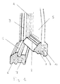
- Figure 1 shows a perspective view and partial section of a carpentry whose structural elements are made with plywood material according to the invention.
- the carpentry is composed of a part intended to be installed and a movable part.
- Each part is made up a frame obtained by assembling crosspieces (1 for the part to be laid, 2 for the mobile part) and uprights (3 for the part to be laid, 4 for the mobile part).
- Glazing 5 is arranged in the movable part.
- the sleepers and uprights 1, 2, 3, 4 form the structural elements of the joinery and are manufactured with the plywood material according to the invention.
- the vertical section of the crosspieces 1, 2 of the joinery shows the material structure.
- a polymer ply 6, 8, made of polystyrene or PVC by example, is located on the outside of the carpentry and a fold of wood 7, 10 for example in oak, fir or exotic wood, is located on its face internal.
- the folds are usually elongated. They are assembled between them according to a planar or substantially planar contact surface and have reliefs on the outside and inside of the frame profiles. These meet functional needs and / or aesthetic. At least one ply of wood 7, 9, 10 can be composed of several elements of wood assembled, for example according to the technique squares.
- the structural elements 1, 2, 3, 4 of the joinery can include several plies of wood 9, 10 for example assembled by gluing, as shown in Figure 1, on the cross section of the opening.
- This type of plywood assembly is usually implemented on assembly lines of squares.
- Polymer ply 6, 8 can be obtained from an extruded profile. The latter can be full or hollow. he can also have cells.
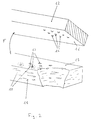
- FIG. 2 represents a diagram of folds to be assembled to constitute the multilayer material according to the invention.
- a ply of polymer 12 is presented facing a ply of wood 11.
- the assembly is carried out by bringing the two into contact surfaces 15, 16 by approximation according to arrow F, and application of a means adapted to cause heating and penetration of the polymer between wood fibers across the contact surface.
- This figure also illustrates a way to strengthen the bond mechanical between wood and polymer.
- Cavities 13, whose shapes, in particular the contours and the depth, are not limited, are created on the surface 15 of the ply of wood 11.
- the ply of polymer 12 may comprise reliefs 14 of shape corresponding to the cavities 13 and susceptible to be arranged opposite the cavities 13 of the ply of wood 11. During the assembly of these reliefs 14 penetrates into the cavities 13.
- a heating means makes it possible to soften at least part of the polymer.
- This means can be applied before or during the approximation of the two plies 11, 12 or after their next contact surfaces 15, 16. After contact and application of pressure the polymer penetrates between the wood fibers to form bonding areas.
- the connection zones can occupy all or part of the surface of contact obtained by joining surfaces 15 and 16. These connecting zones can, for example, be formed by the diffusion of the polymer in the walls of the cavities and extend in an area 17 at the surface 15 of the wood which includes a cavity and an area which borders it.
- the reliefs 14 are not arranged in look of cavities 13 and are arranged during assembly on the surface 15 of the wood. This gives areas where the local pressure is higher than the average pressure applied and this can promote the diffusion of the polymer in the areas of the wood in contact with these reliefs.
- FIG. 3 represents a variant of the diagram of the plies to be assembled to constitute the plywood material according to the invention.
- grooves 23 are cut in the wooden ply 21 along its length.
- One variant is to create in the wood grooves leading to the width of the ply of wood.
- the polymer ply 22 may include reliefs 24, which may or may not be fit into the grooves 23.
- the reliefs 24 are continuous bands of polymer projecting from the surface 26 of the polymer ply 22 and susceptible to be arranged opposite the grooves 23 of the wood.
- the reliefs consist of discontinuous studs which can penetrate the grooves 23 of the wood.
- the shape and the dimension of the reliefs 24 are such that the polymer which constitutes them does not occupy the entire volume of the groove 23 and a continuous channel is obtained at the bottom of the grooves after assembly on the entire length and / or width of the timber.
- This provides a means for evacuating through a face located at least one end 27 of the ply material, the moisture which can be retained by the polymer fold and thus facilitate the breathing of the wood. The risk of wood decay is then significantly reduced.
- the plies of wood and polymer assembled according to Figures 2 and 3 are represented with a parallelepiped shape.
- the material obtained ready for machining to shape a joinery element such as 1, 2, 3, 4 shown in Figure 1.
- one or more folds are shaped before they are assembled (in particular by extruding the polymer or woodworking) so that the manufacture of joinery elements is done without machining or with partial machining of the plywood material.
- the assembly in particular in the form of a frame, of elements structural such as 1, 2, 3, 4 made with a multi-ply material according to the invention having grooves as shown in FIG. 3 maybe carried out so that the grooves 23 open into the open air, a once the frame assembled.
- the frame we gather, for example at a right angle, the structural elements so that the polymer fold is located towards the outside and the fold of wood towards the inside.
- the assembly of the elements can take place in such a way that one face situated at one end 27 of one elements is in contact with a face perpendicular to the surface of wood and polymer of the other element, corresponding to its great length.
- the assembly can also be done by bringing together structural elements whose ends have been cut according to bias cuts.
- This assembly can be mechanical or obtained by gluing. We ensure that the grooves are not blocked. Lights can, for example, be drilled in an element opposite grooves present in the other element to be assembled to ensure circulation between the plywood channels, the lights and the open air.
- Another embodiment consists in assembling two elements whose grooves have been cut in a different direction, for example lengthwise for one and lengthwise width for the other. We assemble the elements so that the grooves in the length are opposite with those across the width. These are arranged so that that they open into the open air on at least one face of the frame, after assembly.
- these grooves 23 can play a hooking role. mechanical as well as the cavities 13 described in FIG. 2. The role bonding can be obtained even if the polymer does not occupy all the volume of the grooves 23. It is also possible to combine the two mechanical reinforcement modes by creating cavities and grooves at the wood fold surface.
- FIG. 4 represents a vertical section of the plywood material when two plies are joined together and more particularly illustrates the connection zone.
- a ply of wood 31 is maintained in contact with a ply of polymer 32.
- a pressure, P is applied between the two folds.
- the polymer ply is softened so that part of this material diffuses between the wood fibers in a bonding area 36.
- This softening can be obtained by energy conversion mechanical heat using a vibratory system 33.
- the area of bond extends substantially over the exposed surface by means 33.
- the polymer can penetrate part of the less than the corresponding volume. Polymer can penetrate into wood around the walls of these cavities or grooves in an area 37 which makes then part of the connecting zone 36.
- a sonotrode 33 for welding by ultrasound when you want to obtain punctual connections between wood and the polymer. This case corresponds, for example, to the diagram in Figure 2 where polymer studs 14 can be inserted into cavities 13 of the wood and where an example of point connection zones 17 is illustrated.
- the application of a sonotrode to create a bonding area punctual is usually carried out in a frequency range of 20 to 40 KHz, for holding times which vary for example from 0.2 to 10 seconds.
- the folds to be assembled are positioned so that the areas link to be created are opposite with the sonotrode heads. These are applied to a ply to heat the polymer at several points and form the bond. The folds are then moved so that a other part to be assembled is arranged opposite the sonotrode heads.
- a variant consists in placing a set of heads over the entire surface folds to be assembled in order to carry out the welding operation in a single step.
- the application of a tool for vibration welding leads to relative displacements, generally of an amplitude of the order of 0.5 to 2 mm, of the two materials in contact to be assembled.
- the frequency usually used is in the range of 100 to 500 HZ.
- the friction of the two materials leads to heating of the polymer which softens and a pressure, for example, of the order of 0.5 to 10 N / mm 2 , allows it to penetrate into the wood.
- the areas excited by the vibrations are generally large enough for the folds to be linked across their width during an elementary welding operation.
- To create the connections along the length of the folds to be assembled it is possible, as before, either to move the folds and successively create connection zones, or to have a set of tools for vibration welding along the length of the folds.
- the bonding areas thus formed can be either continuous over the entire contact surface between ply of wood and ply of polymer, or discontinuous and occupy only part of the surface.
- FIG. 4 also illustrates the penetration of the polymer into a hollow in the wood 35.
- the hollow 35 can correspond as well to the section of a cavity 13 according to FIG. 2 as to that of a groove 23 according to FIG. 3.
- a relief 34 of the polymer ply can be introduced into the hollow space of the wood. This relief can be mechanically excited by the vibratory system and a part of the polymer diffuses in an area 37, around the walls of the cavities or the grooves of the wood.
- Variants of the hollow 35 can correspond to several shapes wood cutting. It is possible to make, for example, a cut bias, a whistle cutout or a dovetail cutout in the wood. These different forms of cutting can be chosen for improve the mechanical bonding between wood and polymer: in fact, the geometry of these cutouts can make it possible to embed the polymer in the wood, making it more difficult to tear off the two folds.
- the invention is not limited to these particular types of embodiment and must be interpreted in a nonlimiting manner and encompassing any type of plywood material consisting of at least one ply of wood and one ply of polymer bonded by polymer penetration between wood fibers on at minus part of the surface between the folds, as well as any frame carpentry or any part of a carpentry set of which only some joinery elements consist at least in part of this material multiply.
Abstract
Description
L'invention se rapporte au domaine de la menuiserie et concerne plus particulièrement un matériau, utilisable comme élément structurel de menuiserie, constitué de plis de matière assemblés, un procédé de fabrication et un dispositif de fabrication.The invention relates to the field of carpentry and concerns more particularly a material, usable as a structural element carpentry, consisting of folds of material assembled, a process of manufacturing and a manufacturing device.
De manière générale, les menuiseries extérieures telles que croisées, fenêtres, portes, fermetures ou les menuiseries intérieures telles que portes ou huisseries sont composées d'éléments structurels qui forment le cadre d'un ouvrage assemblé. Ces éléments structurels sont généralement nommés montants et traverses.In general, exterior joinery such as cross, windows, doors, closings or interior joinery such as doors or frames are made up of structural elements which form the part of an assembled work. These structural elements are generally called uprights and crosspieces.
Le cadre peut être fixe et constituer une menuiserie tel un montant dormant, un bâti ou une huisserie, ou être mobile et constituer une menuiserie tel un vantail ou un ouvrant.The frame can be fixed and constitute a carpentry as an amount frame, a frame or a frame, or be mobile and constitute a carpentry such as a leaf or an opening.
Les cadres mobiles, souvent dénommés châssis, sont généralement pourvus de panneaux ou d'éléments de vitrage qui permettent d'obturer les surfaces entre les éléments structurels.Movable frames, often referred to as chassis, are generally provided with panels or glazing elements which allow sealing the surfaces between the structural elements.
Usuellement ces éléments structurels sont en bois ou en polymère.Usually these structural elements are made of wood or polymer.
Le bois, chêne massif, bois exotiques, pins par exemple, est apprécié pour ses qualités esthétiques et sa résistance. Néanmoins il doit être protégé par des écrans protecteurs contre les intempéries (pluie, soleil, gel). Ces revêtements doivent être renouvelés régulièrement ce qui constitue une contrainte et un surcoût dans l'utilisation de ce type de matériau pour menuiserie.Wood, solid oak, exotic woods, pines for example, is appreciated for its aesthetic qualities and its resistance. Nevertheless it must be protected by protective screens against bad weather (rain, sun, gel). These coatings must be renewed regularly which constitutes a constraint and an additional cost in the use of this type of carpentry material.
Les éléments structurels en bois sont généralement découpés en
une pièce dans des plateaux de bois ou constitués d'un assemblage de
plusieurs pièces de bois. Cette dernière technique d'assemblage, connue
sous le nom de fabrication de carrelets, est décrite par exemple dans le
brevet FR 2 398 156. On peut par cette technique découper les zones
défectueuses du bois et obtenir par aboutage des éléments structurels en
bois massif de grande qualité et présentant une stabilité améliorée. Cette
technique permet d'obtenir de grandes longueurs de bois massif qui sont
ensuite découpées à la taille de la menuiserie à réaliser.The wooden structural elements are generally cut into
a piece in wooden trays or made up of an assembly of
several pieces of wood. This last known assembly technique
under the name of making squares, is described for example in the
Des matériaux polymères sont également utilisés pour fabriquer des menuiseries. Une matière plastique telle que du polychlorure de vinyl (PVC) est généralement utilisée. Ce matériau est apprécié pour sa stabilité à haute et basse température, sa résistance aux chocs et la tenue dans le temps de sa couleur face aux rayonnements solaires.Polymeric materials are also used to make joinery. A plastic material such as polyvinyl chloride (PVC) is generally used. This material is appreciated for its stability at high and low temperatures, its impact resistance and resistance to time of its color in the face of solar radiation.
Les éléments structurels en PVC sont fabriqués usuellement en grande longueur par extrusion et découpés ultérieurement à la taille souhaitée de la menuiserie.PVC structural elements are usually manufactured in great length by extrusion and later cut to size desired joinery.
L'invention a pour objet un nouveau matériau, particulièrement adapté à la fabrication d'éléments structurels de menuiserie, qui associe les qualités recherchées dans les menuiseries en bois et celles que confère l'usage d'un polymère. Il permet de réaliser des menuiseries dont la face située à l'intérieur d'un local est en bois et au moins une partie de la face située à l'extérieur est en polymère. Cette disposition permet d'obtenir les avantages procurés par les deux matériaux. En effet la face située à l'intérieur n'est pas affectée par des intempéries et ne reçoit qu'un éclairement modeste : le bois est préservé et ses qualités décoratives peuvent être mises en valeur. La partie en polymère de la face située à l'extérieur présente les qualités requises de résistance tant aux intempéries qu'aux rayonnements.The subject of the invention is a new material, particularly suitable for the manufacture of structural joinery elements, which combines the qualities sought in wood joinery and those that confer the use of a polymer. It allows to realize joinery whose face located inside a room is made of wood and at least part of the face located outside is made of polymer. This arrangement provides the advantages of both materials. Indeed the face located at the interior is not affected by bad weather and receives only one modest lighting: the wood is preserved and its decorative qualities can be highlighted. The polymer part of the face located at the exterior presents the required qualities of resistance both to weather than radiation.
L'invention propose un matériau multiplis pour éléments de menuiserie, constitué d'au moins un pli de bois, tel qu'au moins un pli de bois est lié à au moins un pli de polymère avec pénétration du polymère entre les fibres du bois dans une ou des zones de liaison s'étendant sur au moins une partie de la surface de contact entre les plis.The invention provides a multilayer material for elements of carpentry, consisting of at least one ply of wood, such as at least one ply of wood is bound to at least one ply of polymer with polymer penetration between the wood fibers in one or more bonding zones extending over at minus part of the contact surface between the folds.
De cette manière une liaison intime est assurée entre le bois et le polymère et un matériau continu est obtenu qui peut être façonné pour fabriquer des éléments de menuiserie.In this way an intimate connection is ensured between the wood and the polymer and a continuous material is obtained which can be shaped to manufacture carpentry elements.
Selon une variante avantageuse, l'invention s'applique à au moins un pli de bois massif.According to an advantageous variant, the invention applies to at least a ply of solid wood.
On entend par « pli de bois massif », un élément en bois d'une épaisseur telle que le pli posé sur sa tranche ne se déforme pas sous son son propre poids. L'épaisseur d'un pli de bois massif est typiquement de l'ordre de quelques millimètres, notamment plus de 5 millimètres.The term "solid wood ply" means a wooden element of thickness such that the fold placed on its edge does not deform under its its own weight. The thickness of a ply of solid wood is typically on the order of a few millimeters, especially more than 5 millimeters.
Selon une réalisation préférée de l'invention, un des plis de bois est constitué d'un assemblage de carrelet.According to a preferred embodiment of the invention, one of the plies of wood is consisting of an assembly of plaice.
De cette manière on obtient des éléments de menuiserie avec une partie en bois massif. Cette disposition est particulièrement adaptée pour les bois de chêne.In this way we obtain joinery elements with a part in solid wood. This arrangement is particularly suitable for oak woods.
Selon une variante avantageuse de l'invention, un pli de polymère est constitué de polystyrène ou de polychlorure de vinyl.According to an advantageous variant of the invention, a polymer ply consists of polystyrene or polyvinyl chloride.
Selon une réalisation de l'invention, un pli de bois comporte au moins une cavité dans au moins une zone de liaison. De cette manière, la liaison entre le pli de bois et le pli de polymère est renforcée par la pénétration du polymère dans au moins une partie du volume des cavités. Un ancrage mécanique renforcé est ainsi obtenu entre les plis.According to one embodiment of the invention, a ply of wood comprises at at least one cavity in at least one connecting zone. In this way, the bond between the ply of wood and the ply of polymer is reinforced by the penetration of the polymer into at least part of the volume of the cavities. A reinforced mechanical anchoring is thus obtained between the plies.
Selon une réalisation préférée de l'invention, un pli de bois comporte une ou des rainures sur sa surface en contact avec un pli de polymère et ces rainures débouchent à l'air libre, sur une face au moins du matériau multiplis. De cette manière, il est possible de favoriser l'évacuation de l'humidité qui peut s'accumuler à l'interface du bois et du polymère. On augmente ainsi l'aération du bois et on diminue très sensiblement les risques de pourrissement du bois.According to a preferred embodiment of the invention, a ply of wood comprises one or more grooves on its surface in contact with a polymer fold and these grooves open into the open air, on at least one face of the material multiply. In this way, it is possible to promote the evacuation of moisture which can accumulate at the interface of wood and polymer. We this increases the ventilation of the wood and the risks of wood decay.
Selon une réalisation de l'invention, au moins une des rainures, comme précédemment explicitée, est remplie dans une partie de son volume par le polymère, cette partie pouvant former zone de liaison. Il est ainsi possible de combiner dans une même rainure les fonctions d'évacuation de l'humidité et d'ancrage mécanique entre les plis.According to one embodiment of the invention, at least one of the grooves, as previously explained, is fulfilled in part of its volume by the polymer, this part possibly forming a bonding zone. It is thus possible to combine in one groove the functions moisture evacuation and mechanical anchoring between the folds.
Selon une réalisation de l'invention, le matériau est obtenu avec un pli de polymère qui présente des reliefs sur la face à lier au bois. Ces reliefs sont susceptibles de coopérer avec les plis de bois, ou les cavités, ou les rainures pour favoriser la pénétration du polymère dans le bois.According to one embodiment of the invention, the material is obtained with a polymer fold which has reliefs on the face to be bonded to the wood. These reliefs are likely to cooperate with the folds of wood, or the cavities, or the grooves to favor the penetration of the polymer into the wood.
L'invention concerne également un cadre de menuiserie, apte à recevoir au moins un vitrage ou un panneau, dont au moins un élément, notamment un montant ou une traverse est fabriqué à partir du matériau multiplis tel que décrit ci-dessus. De cette manière, il est possible d'obtenir un cadre de menuiserie dont au moins une partie d'une face est en polymère et dont l'autre est constituée de bois.The invention also relates to a carpentry frame, suitable for receive at least one glazing or panel, including at least one element, in particular an upright or a crosspiece is made from the material plywood as described above. In this way it is possible to obtain a carpentry frame of which at least part of a face is made of polymer and the other of which is made of wood.
Selon une variante préférée de l'invention, un ou des matériaux multiplis que comprend le cadre de menuiserie ci-dessus, comporte des rainures entre bois et polymère comme exposé ci-dessus. Les montants ou traverses qui composent le cadre sont agencés de manière à ce que les rainures débouchent à l'air libre et permettent l'évacuation de l'humidité. Ce type de montage peut être obtenu en assemblant, par exemple, un montant et une traverse constitués du matériau multiplis comportant des rainures et l'un de ces deux éléments est muni de lumières traversantes, disposées en regard des rainures de l'autre élément. Il est également possible, par exemple, d'assembler un montant et une traverse constitués chacun d'un élément de matériau multiplis comportant des rainures disposées, pour un élément dans le sens de sa longueur et pour l'autre dans le sens de sa largeur.According to a preferred variant of the invention, one or more materials plywood that includes the joinery frame above, has grooves between wood and polymer as described above. The amounts or sleepers that make up the frame are arranged so that the grooves open into the air and allow the evacuation of moisture. This type of assembly can be obtained by assembling, for example, a post and cross member made of plywood material comprising grooves and one of these two elements is fitted with through lights, arranged opposite the grooves of the other element. he is also possible, for example, to assemble a post and a cross member each of a multi-ply material element having grooves arranged, for one element in the direction of its length and for the other across its width.
L'invention concerne également un procédé de fabrication du matériau multiplis où la liaison entre un pli de bois et un pli de polymère est obtenue par l'échauffement du polymère dans au moins une zone en contact avec le bois et en appliquant une pression suffisante pour faire pénétrer le polymère dans le bois. Tout moyen connu peut être utilisé pour chauffer la face à assembler du polymère. De préférence, on utilisera des techniques de miroirs chauffants positionnés momentanément en regard de la surface à chauffer ou des techniques d'échauffement par transformation d'énergie mécanique en chaleur.The invention also relates to a method for manufacturing the plywood material where the bond between a ply of wood and a ply of polymer is obtained by the heating of the polymer in at least one zone in contact with the wood and applying enough pressure to make penetrate the polymer into the wood. Any known means can be used to heat the face to be assembled of the polymer. Preferably, we will use heated mirror techniques positioned momentarily in look at the surface to be heated or techniques for heating by transformation of mechanical energy into heat.
Selon un mode de réalisation préféré, l'échauffement du polymère est obtenu par l'application d'ultrasons ou de vibrations sur l'un des plis. On obtient ainsi un ramollissement du polymère dans les zones excitées par les ultrasons ou les vibrations, à l'interface avec le bois.According to a preferred embodiment, the heating of the polymer is obtained by applying ultrasound or vibration to one of the folds. A softening of the polymer is thus obtained in the excited areas. by ultrasound or vibration, at the interface with wood.
L'invention concerne également un dispositif de fabrication du matériau multiplis selon l'invention, comportant un assemblage de plusieurs plis de bois. Ce dispositif comprend des moyens pour assembler par collage sous pression les plis de bois qui coopèrent avec des moyens pour échauffer le polymère de sorte que la liaison bois/polymère s'effectue conjointement à l'assemblage des plis de bois. Il est possible, par exemple, d'encoller pendant une étape les plis de bois auxquels on adjoint un pli de polymère. Les différents plis sont ensuite rapprochés et introduits dans un système de pressage dont un plateau comprend des moyens de transformation d'énergie mécanique en chaleur, par exemple du type sonotrode pour ultrasons ou dispositif de soudure par vibration. Ces derniers permettent l'échauffement du polymère et la pression appliquée permet d'assembler conjointement les plis de bois entre eux et le pli de polymère sur un pli de bois.The invention also relates to a device for manufacturing the plywood material according to the invention, comprising an assembly of several folds of wood. This device includes means for assembling by pressure bonding the plies of wood which cooperate with means to heat the polymer so that the wood / polymer bond is made together with the assembly of the plies of wood. It is possible, for example, to glue during one step the wooden folds to which we add a fold of polymer. The different folds are then brought together and introduced into a pressing system, a plate of which comprises means for transformation of mechanical energy into heat, for example of the type sonotrode for ultrasound or vibration welding device. These these allow the polymer to heat up and the pressure applied allows the wooden plies to be joined together and the ply of polymer on a fold of wood.
D'autres détails et caractéristiques avantageux de l'invention ressortiront ci-après, de la description d'exemples de réalisation de l'invention en référence aux figures annexées qui représentent :
- figure 1 : menuiserie dont les éléments de structure sont fabriqués avec le matériau multiplis selon l'invention ;
- figure 2 : schéma des plis à assembler selon l'invention ;
- figure 3 : variante du schéma des plis à assembler selon l'invention ;
- figure 4 : coupe verticale du matériau multiplis pendant l'assemblage.
- Figure 1: carpentry whose structural elements are made with the plywood material according to the invention;
- Figure 2: diagram of the folds to be assembled according to the invention;
- FIG. 3: variant of the diagram of the folds to be assembled according to the invention;
- Figure 4 : vertical section of the multilayer material during assembly.
On précise tout d'abord que, par souci de clarté, toutes les figures ne respectent pas rigoureusement les proportions entre les divers éléments représentés.First, it should be noted that, for the sake of clarity, all the figures do not strictly respect the proportions between the various represented elements.
La figure 1 représente une vue en perspective et coupe partielle d'une menuiserie dont les éléments structurels sont fabriqués avec le matériau multiplis selon l'invention. Figure 1 shows a perspective view and partial section of a carpentry whose structural elements are made with plywood material according to the invention.
Selon cette représentation, la menuiserie est composée d'une partie
destinée à être posée et d'une partie mobile. Chaque partie est constituée
d'un cadre obtenu par assemblage de traverses (1 pour la partie à poser, 2
pour la partie mobile) et de montants (3 pour la partie à poser, 4 pour la
partie mobile). Un vitrage 5 est disposé dans la partie mobile. Les
traverses et montants 1, 2, 3, 4 forment les éléments structurels de la
menuiserie et sont fabriqués avec le matériau multiplis selon l'invention.
La coupe verticale des traverses 1, 2 de la menuiserie fait apparaítre la
structure du matériau. Un pli de polymère 6, 8, en polystyrène ou PVC par
exemple, est situé sur la face externe de la menuiserie et un pli de bois
7, 10 par exemple en chêne, sapin ou bois exotiques, est situé sur sa face
interne.According to this representation, the carpentry is composed of a part
intended to be installed and a movable part. Each part is made up
a frame obtained by assembling crosspieces (1 for the part to be laid, 2
for the mobile part) and uprights (3 for the part to be laid, 4 for the
mobile part).
Les plis sont usuellement de forme allongée. Ils sont assemblés
entre eux suivant une surface de contact plane ou sensiblement plane et
présentent du côté extérieur et du côté intérieur du cadre des reliefs
profilés. Ces derniers répondent à des besoins fonctionnels et/ou
esthétiques. Au moins un pli de bois 7, 9, 10 peut être composé de
plusieurs éléments de bois assemblés, par exemple suivant la technique
des carrelets.The folds are usually elongated. They are assembled
between them according to a planar or substantially planar contact surface and
have reliefs on the outside and inside of the frame
profiles. These meet functional needs and / or
aesthetic. At least one ply of
Les éléments structurels 1, 2, 3, 4 de la menuiserie peuvent
comporter plusieurs plis de bois 9, 10 par exemple assemblés par collage,
comme représenté en figure 1, sur la section de la traverse de l'ouvrant.
Ce type d'assemblage de plis de bois est usuellement mis en oeuvre sur les
lignes d'assemblage de carrelets. Le pli de polymère 6, 8 peut être obtenu
à partir d'un profilé extrudé. Ce dernier peut être plein ou creux. Il peut
également comporter des alvéoles.The
La figure 2 représente un schéma de plis à assembler pour constituer le matériau multiplis selon l'invention. FIG. 2 represents a diagram of folds to be assembled to constitute the multilayer material according to the invention.
Selon cette représentation, un pli de polymère 12 est présenté face à
un pli de bois 11. L'assemblage s'effectue par mise en contact des deux
surfaces 15, 16 par rapprochement selon la flèche F, et application d'un
moyen adapté pour provoquer l'échauffement et la pénétration du
polymère entre les fibres du bois à travers la surface de contact.According to this representation, a ply of
Cette figure illustre également un moyen de renforcer la liaison
mécanique entre le bois et le polymère. Des cavités 13, dont les formes,
notamment les contours et la profondeur, ne sont pas limitées, sont créées
à la surface 15 du pli de bois 11. Le pli de polymère 12 peut comprendre
des reliefs 14 de forme correspondante aux cavités 13 et susceptibles
d'être disposés en regard des cavités 13 du pli de bois 11. Pendant
l'assemblage ces reliefs 14 pénètrent dans les cavités 13.This figure also illustrates a way to strengthen the bond
mechanical between wood and polymer.
Un moyen de chauffage permet de ramollir au moins une partie du
polymère. Ce moyen peut être appliqué avant ou pendant le
rapprochement des deux plis 11, 12 ou après leur mise en contact suivant
les surfaces 15, 16. Après contact et application d'une pression le
polymère pénètre entre les fibres de bois pour former des zones de liaison.
Les zones de liaison peuvent occuper tout ou partie de la surface de
contact obtenue en réunissant les surfaces 15 et 16. Ces zones de liaison
peuvent, par exemple, être constituées par la diffusion du polymère dans
les parois des cavités et s'étendre dans une zone 17 à la surface 15 du
bois qui comprend une cavité et une zone qui la borde.A heating means makes it possible to soften at least part of the
polymer. This means can be applied before or during the
approximation of the two
Il est également possible que des reliefs 14 ne soient pas disposés en
regard de cavités 13 et soient disposés pendant l'assemblage sur la
surface 15 du bois. On obtient ainsi des zones où la pression locale est
supérieure à la pression moyenne appliquée et on peut ainsi favoriser la
diffusion du polymère dans les zones du bois en contact avec ces reliefs.It is also possible that the
La figure 3 représente une variante du schéma des plis à assembler pour constituer le matériau multiplis selon l'invention. FIG. 3 represents a variant of the diagram of the plies to be assembled to constitute the plywood material according to the invention.
Selon cette représentation, des rainures 23 sont découpées dans le
pli de bois 21 dans le sens de sa longueur. Une variante consiste à créer
dans le bois des rainures débouchant sur la largeur du pli de bois.According to this representation,
Le pli de polymère 22 peut comporter des reliefs 24, aptes ou non à
s'insérer dans les rainures 23.The polymer ply 22 may include
Selon un mode préféré, les reliefs 24 sont des bandes continues de
polymère en saillie à la surface 26 du pli de polymère 22 et susceptibles
d'être disposées en regard des rainures 23 du bois. Selon un autre mode
de réalisation les reliefs sont constitués de plots discontinus qui peuvent
pénétrer dans les rainures 23 du bois.According to a preferred embodiment, the
De préférence, la forme et la dimension des reliefs 24 sont tels que le
polymère qui les constitue n'occupe pas tout le volume de la rainure 23 et
un canal continu est obtenu au fond des rainures après assemblage sur
toute la longueur et/ou la largeur du bois.Preferably, the shape and the dimension of the
On obtient ainsi un moyen permettant d'évacuer par une face située
à au moins une extrémité 27 du matériau multiplis, l'humidité qui peut
être retenue par le pli de polymère et faciliter ainsi la respiration du bois.
Les risques de pourrissement du bois sont alors sensiblement diminués.This provides a means for evacuating through a face located
at least one
Les plis de bois et polymère assemblés suivant les figures 2 et 3 sont représentés avec une forme parallélépipèdique. Le matériau obtenu se prête à un usinage pour façonner un élément de menuiserie tel que 1, 2, 3, 4 représenté sur la figure 1. En variante, un ou plusieurs plis sont façonnés avant leur assemblage (notamment par l'extrusion du polymère ou usinage du bois) de sorte que la fabrication des éléments de menuiserie se fait sans usinage ou avec usinage partiel du matériau multiplis.The plies of wood and polymer assembled according to Figures 2 and 3 are represented with a parallelepiped shape. The material obtained ready for machining to shape a joinery element such as 1, 2, 3, 4 shown in Figure 1. Alternatively, one or more folds are shaped before they are assembled (in particular by extruding the polymer or woodworking) so that the manufacture of joinery elements is done without machining or with partial machining of the plywood material.
L'assemblage, notamment sous forme de cadre, d'éléments
structurels tels que 1, 2, 3, 4 fabriqués avec un matériau multiplis selon
l'invention présentant des rainures comme représenté à la fig. 3 peut être
effectué de manière à ce que les rainures 23 débouchent à l'air libre, une
fois le cadre assemblé.The assembly, in particular in the form of a frame, of elements
structural such as 1, 2, 3, 4 made with a multi-ply material according to
the invention having grooves as shown in FIG. 3 maybe
carried out so that the
Pour former le cadre, on réunit, par exemple à angle droit, les
éléments structurels de manière à ce que le pli de polymère soit situé vers
l'extérieur et le pli de bois vers l'intérieur. L'assemblage des éléments peut
s'effectuer de manière à ce qu'une face située à une extrémité 27 de l'un
des éléments soit en contact avec une face perpendiculaire à la surface
d'assemblage du bois et du polymère de l'autre élément, correspondant à
sa grande longueur. L'assemblage peut également s'effectuer en
rapprochant des éléments structurels dont les extrémités ont été
découpées suivant des coupes biaises.To form the frame, we gather, for example at a right angle, the
structural elements so that the polymer fold is located towards
the outside and the fold of wood towards the inside. The assembly of the elements can
take place in such a way that one face situated at one
Cet assemblage peut être mécanique ou obtenu par collage. On veille alors à ce que les rainures ne soient pas obturées. Des lumières peuvent, par exemple, être percées dans un élément en regard de rainures présentes dans l'autre élément à assembler afin d'assurer une circulation entre les canaux du matériau multiplis, les lumières et l'air libre.This assembly can be mechanical or obtained by gluing. We ensure that the grooves are not blocked. Lights can, for example, be drilled in an element opposite grooves present in the other element to be assembled to ensure circulation between the plywood channels, the lights and the open air.
Un autre mode de réalisation consiste à assembler deux éléments dont les rainures ont été découpées dans un sens différent, par exemple dans le sens de la longueur de l'élément pour l'un et dans le sens de la largeur pour l'autre. On assemble les éléments de manière à ce que les rainures effectuées dans la longueur soient en regard avec celles effectuées dans la largeur. Ces dernières sont disposées de manière à ce qu'elles débouchent à l'air libre sur au moins une face du cadre, après assemblage.Another embodiment consists in assembling two elements whose grooves have been cut in a different direction, for example lengthwise for one and lengthwise width for the other. We assemble the elements so that the grooves in the length are opposite with those across the width. These are arranged so that that they open into the open air on at least one face of the frame, after assembly.
En outre ces rainures 23 peuvent jouer un rôle d'accrochage
mécanique de même que les cavités 13 décrites en figure 2. Le rôle
d'accrochage peut être obtenu même si le polymère n'occupe pas tout le
volume des rainures 23. Il est également possible d'associer les deux
modes de renfort mécanique en créant des cavités et des rainures à la
surface du pli de bois.In addition, these
La figure 4 représente une coupe verticale du matériau multiplis au moment de l'assemblage de deux plis entre eux et illustre plus particulièrement la zone de liaison. FIG. 4 represents a vertical section of the plywood material when two plies are joined together and more particularly illustrates the connection zone.
Selon cette représentation, un pli de bois 31 est maintenu en
contact avec un pli de polymère 32. Une pression, P, est appliquée entre
les deux plis. Le pli de polymère est ramolli de manière à ce qu'une partie
de ce matériau diffuse entre les fibres du bois dans une zone de liaison
36. Ce ramollissement peut être obtenu par la conversion d'énergie
mécanique en chaleur à l'aide d'un système vibratoire 33. La zone de
liaison s'étend sensiblement sur la surface exposée au moyen
d'échauffement 33. Dans le cas où des cavités ou des rainures 35 ont été
créées à la surface du bois, le polymère peut pénétrer dans une partie au
moins du volume correspondant. Le polymère peut pénétrer dans le bois
autour des parois de ces cavités ou rainures dans une zone 37 qui fait
alors partie de la zone de liaison 36.According to this representation, a ply of
On choisira de préférence une sonotrode 33 pour soudure par
ultrasons quand on désire obtenir des liaisons ponctuelles entre le bois et
le polymère. Ce cas correspond, par exemple, au schéma de la figure 2 où
des plots de polymère 14 peuvent être insérés dans des cavités 13 du bois
et où un exemple de zones de liaison ponctuelle 17 est illustré.We will preferably choose a
Il est également possible d'effectuer des soudures par ultrason qui
créent des zones de liaison ponctuelle pour assembler un pli de polymère
comportant des plots 14 ou des bandes 24 avec un pli de bois comportant
des rainures 23.It is also possible to perform ultrasonic welds which
create point bonding areas to assemble a polymer
L'application d'une sonotrode pour créer une zone de liaison ponctuelle s'effectue usuellement dans une gamme de fréquence de 20 à 40 KHz, pendant des temps de maintien qui varient par exemple de 0,2 à 10 secondes.The application of a sonotrode to create a bonding area punctual is usually carried out in a frequency range of 20 to 40 KHz, for holding times which vary for example from 0.2 to 10 seconds.
Il est possible de combiner plusieurs sonotrodes pour obtenir un outil multitêtes qui permet de souder plusieurs points en même temps. La soudure d'un pli de polymère avec un pli de bois peut s'effectuer alors de manière semi-continue :It is possible to combine several sonotrodes to obtain a multi-head tool which allows to weld several points at the same time. The welding a polymer ply with a wooden ply can then be done semi-continuously:
les plis à assembler sont positionnés de manière à ce que les zones de liaison à créer soient en regard avec les têtes de sonotrode. Celles-ci sont appliquées sur un pli pour échauffer le polymère en plusieurs points et former la liaison. Les plis sont ensuite déplacés de manière à ce qu'une autre partie à assembler soit disposée en regard des têtes de sonotrode. Une variante consiste à disposer un ensemble de têtes sur toute la surface des plis à assembler afin de réaliser l'opération de soudure en une seule étape.the folds to be assembled are positioned so that the areas link to be created are opposite with the sonotrode heads. These are applied to a ply to heat the polymer at several points and form the bond. The folds are then moved so that a other part to be assembled is arranged opposite the sonotrode heads. A variant consists in placing a set of heads over the entire surface folds to be assembled in order to carry out the welding operation in a single step.
On préférera un système de soudure par vibration 33 si on souhaite
que les zones de liaison couvrent de plus grandes surfaces. Cette
technique s'adapte particulièrement au cas envisagé dans le schéma de la
figure 3 notamment, où l'on souhaite lier un pli de polymère, qui peut
comporter des reliefs tels que des bandes continues, avec un pli de bois
dans lequel des rainures ont été découpées.We prefer a
L'application d'un outil pour soudure par vibration conduit à des déplacements relatifs, généralement d'une amplitude de l'ordre de 0,5 à 2 mm, des deux matériaux en contact à assembler. La fréquence usuellement utilisée se situe dans la gamme de 100 à 500 HZ. Le frottement des deux matériaux conduit à un échauffement du polymère qui ramollit et une pression, par exemple, de l'ordre de 0,5 à 10 N/mm2, permet de le faire pénétrer dans le bois. Les zones excitées par les vibrations sont généralement assez grandes pour que les plis soient liés sur leur largeur au cours d'une opération de soudure élémentaire. Pour créer les liaisons sur la longueur des plis à assembler, on peut, comme précédemment soit déplacer les plis et créer successivement des zones de liaison, soit disposer un ensemble d'outils pour soudure par vibration sur la longueur des plis. Les zones de liaison ainsi formées peuvent être soit continues sur l'ensemble de la surface de contact entre pli de bois et pli de polymère, soit discontinues et n'en occuper qu'une partie de la surface.The application of a tool for vibration welding leads to relative displacements, generally of an amplitude of the order of 0.5 to 2 mm, of the two materials in contact to be assembled. The frequency usually used is in the range of 100 to 500 HZ. The friction of the two materials leads to heating of the polymer which softens and a pressure, for example, of the order of 0.5 to 10 N / mm 2 , allows it to penetrate into the wood. The areas excited by the vibrations are generally large enough for the folds to be linked across their width during an elementary welding operation. To create the connections along the length of the folds to be assembled, it is possible, as before, either to move the folds and successively create connection zones, or to have a set of tools for vibration welding along the length of the folds. The bonding areas thus formed can be either continuous over the entire contact surface between ply of wood and ply of polymer, or discontinuous and occupy only part of the surface.
La figure 4 illustre également la pénétration du polymère dans un
creux du bois 35. Le creux 35 peut correspondre aussi bien à la coupe
d'une cavité 13 selon la figure 2 qu'à celle d'une rainure 23 selon la figure
3. Un relief 34 du pli de polymère peut être introduit dans l'espace creux
du bois. Ce relief peut être excité mécaniquement par le système vibratoire
et une partie du polymère diffuse dans une zone 37, autour des parois des
cavités ou des rainures du bois. FIG. 4 also illustrates the penetration of the polymer into a hollow in the
Des variantes du creux 35 peuvent correspondre à plusieurs formes de découpe du bois. Il est possible de réaliser, par exemple, une coupe biaise, une découpe en sifflet ou une découpe en queue d'arronde dans le bois. Ces différentes formes de découpe peuvent être choisies pour améliorer l'accrochage mécanique entre le bois et le polymère : en effet, la géométrie de ces découpes peut permettre d'obtenir un encastrement du polymère dans le bois, rendant ainsi plus difficile l'arrachement des deux plis.Variants of the hollow 35 can correspond to several shapes wood cutting. It is possible to make, for example, a cut bias, a whistle cutout or a dovetail cutout in the wood. These different forms of cutting can be chosen for improve the mechanical bonding between wood and polymer: in fact, the geometry of these cutouts can make it possible to embed the polymer in the wood, making it more difficult to tear off the two folds.
L'invention ne se limite pas à ces types particuliers de réalisation et doit être interprétée de façon non limitative et englobant tout type de matériau multiplis constitué d'au moins un pli de bois et d'un pli de polymère liés par pénétration du polymère entre les fibres du bois sur au moins une partie de la surface entre les plis, ainsi que tout cadre de menuiserie ou toute pièce d'un ensemble menuisé dont seuls certains éléments de menuiserie sont constitués au moins en partie de ce matériau multiplis.The invention is not limited to these particular types of embodiment and must be interpreted in a nonlimiting manner and encompassing any type of plywood material consisting of at least one ply of wood and one ply of polymer bonded by polymer penetration between wood fibers on at minus part of the surface between the folds, as well as any frame carpentry or any part of a carpentry set of which only some joinery elements consist at least in part of this material multiply.
Claims (12)
Applications Claiming Priority (2)
| Application Number | Priority Date | Filing Date | Title |
|---|---|---|---|
| FR9904540 | 1999-04-12 | ||
| FR9904540A FR2791921B1 (en) | 1999-04-12 | 1999-04-12 | MATERIAL FOR JOINERY ELEMENT, WITH FRAME, MANUFACTURING METHOD AND DEVICE THEREOF |
Publications (1)
| Publication Number | Publication Date |
|---|---|
| EP1044802A1 true EP1044802A1 (en) | 2000-10-18 |
Family
ID=9544286
Family Applications (1)
| Application Number | Title | Priority Date | Filing Date |
|---|---|---|---|
| EP00400939A Withdrawn EP1044802A1 (en) | 1999-04-12 | 2000-04-05 | Woodwork unit material, including frame, and process and manufacture device therefore |
Country Status (3)
| Country | Link |
|---|---|
| EP (1) | EP1044802A1 (en) |
| FR (1) | FR2791921B1 (en) |
| PL (1) | PL339588A1 (en) |
Cited By (3)
| Publication number | Priority date | Publication date | Assignee | Title |
|---|---|---|---|---|
| WO2003091017A1 (en) * | 2002-04-04 | 2003-11-06 | GEOD SA (société de droit suisse) | Composite wooden section based on machinable wood and method for making same |
| GB2403978A (en) * | 2003-07-12 | 2005-01-19 | Howarth Timber Windows & Doors | Frame with components of wood and wood/plastic composite |
| WO2008132530A1 (en) * | 2007-04-26 | 2008-11-06 | Natre Gruppen As | Profile for insulating a window frame |
Families Citing this family (1)
| Publication number | Priority date | Publication date | Assignee | Title |
|---|---|---|---|---|
| PL237679B1 (en) * | 2017-10-18 | 2021-05-17 | Politechnika Poznanska | Layered laminate and method for plying up |
Citations (3)
| Publication number | Priority date | Publication date | Assignee | Title |
|---|---|---|---|---|
| GB2216580A (en) * | 1988-01-07 | 1989-10-11 | Edward Wilkinson | A composite section frame element |
| DE4002593A1 (en) * | 1990-01-30 | 1991-08-01 | Paul Wolter | Decorative sheet with profiled surface - is produced by extruding polystyrene on to real decorative veneer, hot pressing, thermo-forming and forming polystyrene behind the sheet |
| US5423933A (en) * | 1993-05-19 | 1995-06-13 | Horian; Richard C. | Fabrication of plastic and wood veneer composite |
-
1999
- 1999-04-12 FR FR9904540A patent/FR2791921B1/en not_active Expired - Lifetime
-
2000
- 2000-04-05 EP EP00400939A patent/EP1044802A1/en not_active Withdrawn
- 2000-04-11 PL PL00339588A patent/PL339588A1/en unknown
Patent Citations (3)
| Publication number | Priority date | Publication date | Assignee | Title |
|---|---|---|---|---|
| GB2216580A (en) * | 1988-01-07 | 1989-10-11 | Edward Wilkinson | A composite section frame element |
| DE4002593A1 (en) * | 1990-01-30 | 1991-08-01 | Paul Wolter | Decorative sheet with profiled surface - is produced by extruding polystyrene on to real decorative veneer, hot pressing, thermo-forming and forming polystyrene behind the sheet |
| US5423933A (en) * | 1993-05-19 | 1995-06-13 | Horian; Richard C. | Fabrication of plastic and wood veneer composite |
Cited By (3)
| Publication number | Priority date | Publication date | Assignee | Title |
|---|---|---|---|---|
| WO2003091017A1 (en) * | 2002-04-04 | 2003-11-06 | GEOD SA (société de droit suisse) | Composite wooden section based on machinable wood and method for making same |
| GB2403978A (en) * | 2003-07-12 | 2005-01-19 | Howarth Timber Windows & Doors | Frame with components of wood and wood/plastic composite |
| WO2008132530A1 (en) * | 2007-04-26 | 2008-11-06 | Natre Gruppen As | Profile for insulating a window frame |
Also Published As
| Publication number | Publication date |
|---|---|
| PL339588A1 (en) | 2000-10-23 |
| FR2791921B1 (en) | 2001-05-18 |
| FR2791921A1 (en) | 2000-10-13 |
Similar Documents
| Publication | Publication Date | Title |
|---|---|---|
| BE1000350A5 (en) | Hanger glass panel. | |
| CA2590679C (en) | Complex partition glass consisting of at least two adjacent glass elements, and method for producing said complex partition glass | |
| EP0280228B1 (en) | Combined wood and concrete floor | |
| FR2622525A1 (en) | METHOD FOR MANUFACTURING BODY PANEL OF VEHICLE WITH SANDWICH STRUCTURE WITH HONEYCOMB | |
| EP2709826B1 (en) | Composite panel and process for producing same | |
| EP1651424B1 (en) | Method for assembling elements of a structure comprising a honeycomb core | |
| FR2546221A1 (en) | Double glazed window with plastics frame | |
| EP1956173B1 (en) | Frame of a sliding door or window including a single-piece hidden leaf head | |
| EP1044802A1 (en) | Woodwork unit material, including frame, and process and manufacture device therefore | |
| EP1106342A1 (en) | Laminated glass pane for a glass structure | |
| FR2536110A1 (en) | SYSTEM OF METAL PROFILES FOR OPENING FRAMES, PARTICULARLY BREAKING THERMAL BRIDGES, OPENINGS THUS OBTAINED AND PRESS TOOL FOR MACHINING THESE PROFILES | |
| EP1321594B1 (en) | Insulation composite | |
| FR2970729A1 (en) | Laminated composite hinged shutter for e.g. window of building, has core comprising finishing pieces whose faces form edges of shutter such that dimension of shutter is adjusted by cutting portion of finishing pieces along side of shutter | |
| EP1573147A1 (en) | Panel for wall thermoacoustic insulation | |
| LU87974A1 (en) | THERMAL DISCONTINUITY PROFILE ASSEMBLIES, MACHINE FOR MAKING SUCH ASSEMBLIES AND STRUCTURES COMPOSED OF SUCH ASSEMBLIES | |
| FR2959956A1 (en) | Method for realizing trim in facade of e.g. non-deformable door in building site, involves cutting of trim at length of inverse T-shaped groove, introducing strip into corresponding branch and fitting trim in groove | |
| BE1010530A4 (en) | Element retaining encollable plastic. | |
| EP3714114B1 (en) | Plateau de bardage profilé comportant un joint d'étanchéité, et procédé de réalisation d'un tel plateau | |
| EP1830027A1 (en) | Woodwork element capable of accommodating a glazed part and element with corresponding glass function | |
| FR2732707A1 (en) | Wooden form to create openings for doors and windows in concrete screens or walls | |
| FR2943367A1 (en) | LAMINATION-TYPE CONSTRUCTION ELEMENT AND METHOD OF MAKING SAME | |
| FR3105280A1 (en) | Panel for the realization of a free-standing floor covering | |
| WO2005108694A1 (en) | Panel assembly method | |
| EP0617181A1 (en) | Thermally insulating roof with acoustical absorption | |
| FR2939812A1 (en) | Wooden wall element for forming e.g. floor of wooden framework building, has spacer panel comprising opposite longitudinal portions flatably fixed against longitudinal face of carrying stringer and longitudinal face of additional stringer |
Legal Events
| Date | Code | Title | Description |
|---|---|---|---|
| PUAI | Public reference made under article 153(3) epc to a published international application that has entered the european phase |
Free format text: ORIGINAL CODE: 0009012 |
|
| AK | Designated contracting states |
Kind code of ref document: A1 Designated state(s): AT BE CH CY DE DK ES FI FR GB GR IE IT LI LU MC NL PT SE |
|
| AX | Request for extension of the european patent |
Free format text: AL;LT;LV;MK;RO;SI |
|
| 17P | Request for examination filed |
Effective date: 20001115 |
|
| AKX | Designation fees paid |
Free format text: AT BE CH CY DE DK ES FI FR GB GR IE IT LI LU MC NL PT SE |
|
| 17Q | First examination report despatched |
Effective date: 20030903 |
|
| STAA | Information on the status of an ep patent application or granted ep patent |
Free format text: STATUS: THE APPLICATION HAS BEEN WITHDRAWN |
|
| 18W | Application withdrawn |
Effective date: 20031210 |
|
| R18W | Application withdrawn (corrected) |
Effective date: 20031222 |