BACKGROUND OF THE INVENTION
1. Field of the Invention
The present invention relates to a rotor for a permanent magnet type
rotating machine, which operates as an induction machine at the machine's
starting and also a synchronizing machine at the rated driving.
2. Description of the Related Art
Generally, the permanent magnet-reluctance type rotating machine
comprises a stator having armature windings and a rotor rotating inside the
stator. In the machine, the rotor is provided with no windings forming a
field system but permanent magnets disposed on side faces of respective
projecting portions of a rotor core having irregularities on its outer
periphery. Therefore, the machine is characterized in that the structure is
simple in comparison with the conventional wound-rotor type rotating
machine.
Between the rotor core and the stator, this permanent magnet-reluctance
type rotating machine has a small magnetic reluctance about each
projecting portion and a large magnetic reluctance about each recessed
portion due to the structural unevenness on the rotor core. In this way,
there is a difference between the projecting portion and the recessed
portion in terms of magnetic energy stored at a clearance (air gap) between
the rotor core and the stator due to the current flowing through the
armature windings, so that the output is mainly produced by the change in
magnetic energy.
Note, the unevenness about the rotor is not necessarily provided by its
geometrical structure and, in short, the "magnetic" unevenness may be
formed about the rotor. Therefore, the rotating machine may be provided
with a constitution by which the magnetic reluctance and flux can be
changed dependently of the rotational position of the rotor.
Note, the reluctance type rotating machine using no permanent magnet
has a problem of power reduction when the current flowing the armature
windings increases since the leakage flux into the magnetically recessed
portions, i.e. the interpole portions, is increased by the enlargement of
magnetically saturated area in the projecting portions, i.e. the pole
portions.
While, the permanent magnet-reluctance type rotating machine is
capable of avoiding the deterioration of output since the permanent
magnets on respective pole sides of the rotor core do act as the magnetic
reluctance to reduce the leakage flux directing to the interpole portions.
In addition to the above-mentioned function to reduce the leakage flux,
the permanent magnets have an effect to generate the reluctance torque due
to the interaction between their own flux and the flux from the armature
windings.
In this way, the permanent magnet-reluctance type rotating machine is
constructed so as to exhibit different magnetic reluctance dependent on the
rotational position of the rotor due to the magnetic unevenness about the
peripheral face of the rotor core and also ensure the power output since the
leakage flux for the interpole portions is reduced by the permanent
magnets on the pole sides.
In the permanent magnet-reluctance type rotating machine, however,
there is a problem of difficult self starting because the self-retaining torque
is increased by the permanent magnets on the pole sides.
In order to ensure the self starting torque, there have been attempted
many countermeasures, for example, to adopt an inverter as supplementary
starting means, to overlap the rotor with an additional starting cage, etc.
However, these countermeasures cause the structure of the rotating
machine to be complicated in total. Especially in case of the self-starting
cage, there is also raised a problem of increasing the magnetic reluctance
to reduce the main magnetic flux.
Under the situation, the applicant of the present invention has
previously proposed a rotor for the permanent magnet-reluctance type
rotating machine which is capable of improving its starting characteristics
without requiring any supplemental starting means (Japanese Patent
Application No. 10-275797). In this machine, for example, the starting
cage is made of magnetic material and starting conductors are provided in
the form of "deep-groove".
At the machine's starting, this permanent magnet-reluctance type
rotating machine makes the starting conductors on the periphery of the
rotor produce an induction torque corresponding to the change of armature
current, thereby allowing the rotor to operate as the induction machine.
At the machine's rated driving, the permanent magnet-reluctance type
rotating machine allows the rotor to operate as the synchronous machine
by both of the reluctance torque originated in the magnetic unevenness on
the rotor surface and the torque based on the interaction of the flux of the
permanent magnets on the pole sides with the flux from the armature
windings.
As to the above-mentioned "self starting" permanent magnet-reluctance
type rotating machine, it is known that when the flux from the
permanent magnets in the rotor core, namely, "magnet flux" gets large or
the difference in magnetic reluctance between the projecting portions and
the recessed portions of the rotor core gets large, the machine is apt to be
started with difficulty.
It is also known that, conversely, if the magnet flux or reluctance is
small, then the operative conversion is apt to be difficult at the machine's
pull-in as one turning point from the starting operation as the induction
machine to the normal operation as the synchronous machine.
In order to carry out the machine's starting and pull-in without a hitch,
it is necessary to establish the number of magnet flux and the value of
reluctance appropriately.
Despite the fact that the general tendencies of magnet flux and
reluctance upon the machine's starting and pull-in operations has been
recognized as mentioned above, there has not been provided any definite
establishment against the magnet flux and the reluctance yet.
Therefore, there presently exists a situation where, for example, one
permanent magnet-reluctance type is easy to start but hard for pull-in,
while the other rotating machine is easy for its pull-in but hard to start.
SUMMARY OF THE INVENTION
It is therefore an object of the present invention to provide a rotor for a
permanent magnet type rotating machine which is capable of operating as
an induction machine at the machine's starting and also as a synchronizing
machine owing to the smooth "pull in" for the synchronism at the
machine's rated driving.
In order to accomplish the object described above, the present invention
provides a rotor for a permanent magnet type rotating machine having a
stator with armature windings, the rotor comprising a rotor core having a
magnetic unevenness formed in a circumferential direction thereof, with
magnetic portions; a plurality of permanent magnets arranged in the rotor
core so as to negate magnetic flux originating in the armature windings and
also passing between adjoining magnetic poles; and conductors arranged in
the periphery of the rotor core to produce a starting torque by the
generation of induced current at the machine's starting. As the 1st.
feature of the invention, the rotor is constructed so that the average of
magnetic flux in an air gap between the rotor and the stator, which is
produced by the permanent magnets at the armature windings' unexciting,
ranges from 0.1 [T] to 0.7 [T] and the rotor core is constructed so that the
ratio (Lq/Ld) of self-inductance (Lq) of the magnetic portion in a hard-magnetizing
direction to self-inductance (Ld) in an easy-magnetizing
direction under a rated load condition is within a range from 0.1 to 0.8.
With the above arrangement, it is possible to realize the rotating
machine allowing its operation to be transferred from the machine's
starting to the synchronism smoothly.
In common with the inventions according to the 2nd.-7th. features
described later, a rotor for a permanent magnet type rotating machine
having a stator with armature windings, comprises a rotor core having a
magnetic unevenness formed in a circumferential direction thereof, with
magnetic portions; a plurality of permanent magnets arranged in the rotor
core so as to negate magnetic flux originating in the armature windings and
also passing between adjoining magnetic poles; and conductors arranged in
the periphery of the rotor core to produce a starting torque by the
generation of induced current at the machine's starting; wherein a load
connected to the rotor core is substantially proportional to a power
frequency to the power three.
First, the 2nd. feature of the invention resides in that the conductors'
resistivity at the machine's regular driving substantially equals to the
resistivity of aluminum; the rotor is constructed so that the average of
magnetic flux in an air gap between the rotor and the stator, which is
produced by the permanent magnets, ranges from 0.1 [T] to 0.5 [T]; and
the rotor core is constructed so that the ratio (Lq/Ld) of self-inductance
(Lq) of the magnetic portion in a hard-magnetizing direction to self-inductance
(Ld) in an easy-magnetizing direction under a rated load
condition is within a range from 0.1 to 0.8.
The 3rd. feature of the invention resides in that the conductors'
resistivity at the machine's regular driving equals general 110 % on the
assumption that the resistivity of aluminum corresponds to 100 %; the
rotor is constructed so that the average of magnetic flux in an air gap
between the rotor and the stator, which is produced by the permanent
magnets, ranges from 0.2 [T] to 0.6 [T]; and the rotor core is constructed
so that the ratio (Lq/Ld) of self-inductance (Lq) of the magnetic portion in
a hard-magnetizing direction to self inductance (Ld) in an easy-magnetizing
direction under a rated load condition is within a range from
0.1 to 0.7.
The 4th. feature of the invention resides in that the conductors'
resistivity at the machine's regular driving equals general 120 % on the
assumption that the resistivity of aluminum corresponds to 100 %; the
rotor is constructed so that the average of magnetic flux in an air gap
between the rotor and the stator, which is produced by the permanent
magnets, ranges from 0.2 [T] to 0.6 [T]; and the rotor core is constructed
so that the ratio (Lq/Ld) of self-inductance (Lq) of the magnetic portion in
a hard-magnetizing direction to self inductance (Ld) in an easy-magnetizing
direction under a rated load condition is within a range from
0.1 to 0.6.
The 5th. feature of the invention resides in that the conductors'
resistivity at the machine's regular driving equals general 130 % on the
assumption that the resistivity of aluminum corresponds to 100 %; the
rotor is constructed so that the average of magnetic flux in an air gap
between the rotor and the stator, which is produced by the permanent
magnets, ranges from 0.2 [T] to 0.6 [T]; and the rotor core is constructed
so that the ratio (Lq/Ld) of self-inductance (Lq) of the magnetic portion in
a hard-magnetizing direction to self inductance (Ld) in an easy-magnetizing
direction under a rated load condition is within a range from
0.1 to 0.5.
The 6th. feature of the invention resides in that the conductors'
resistivity at the machine's regular driving equals general 140 % on the
assumption that the resistivity of aluminum corresponds to 100 %; the
rotor is constructed so that the average of magnetic flux in an air gap
between the rotor and the stator, which is produced by the permanent
magnets, ranges from 0.3 [T] to 0.6 [T]; and the rotor core is constructed
so that the ratio (Lq/Ld) of self-inductance (Lq) of the magnetic portion in
a hard-magnetizing direction to self inductance (Ld) in an easy-magnetizing
direction under a rated load condition is within a range from
0.1 to 0.5.
The 7th. feature of the invention resides in that the conductors'
resistivity at the machine's regular driving equals general 150 % on the
assumption that the resistivity of aluminum corresponds to 100 %; the
rotor is constructed so that the average of magnetic flux in an air gap
between the rotor and the stator, which is produced by the permanent
magnets, ranges from 0.3 [T] to 0.7 [T]; and the rotor core is constructed
so that the ratio (Lq/Ld) of self-inductance (Lq) of the magnetic portion in
a hard-magnetizing direction to self-inductance (Ld) in an easy-magnetizing
direction under a rated load condition is within a range from
0.1 to 0.4.
In accordance with the respective arrangements of the 2nd. - 7th.
features mentioned above, it is possible to realize the rotating machine
allowing its operation to be transferred from the machine's starting to the
synchronism smoothly.
In common with the inventions according to the 8th.- 13th. features
described later, a rotor for a permanent magnet type rotating machine
having a stator with armature windings, comprises a rotor core having a
magnetic unevenness formed in a circumferential direction thereof, with
magnetic portions; a plurality of permanent magnets arranged in the rotor
core so as to negate magnetic flux originating in the armature windings and
also passing between adjoining magnetic poles; and conductors arranged in
the periphery of the rotor core to produce a starting torque by the
generation of induced current at the machine's starting; wherein a load
connected to the rotor core equals substantial zero in case of less than the
machine's rated rotations, while the load is proportional to a power
frequency to the power three in case of more than the machine's rated
rotations.
The 8th. feature of the invention resides in that the conductors'
resistivity at the machine's regular driving substantially equals to the
resistivity of aluminum; the rotor is constructed so that the average of
magnetic flux in an air gap between the rotor and the stator, which is
produced by the permanent magnets, ranges from 0.1 [T] to 0.5 [T]; and
the rotor core is constructed so that the ratio (Lq/Ld) of self-inductance
(Lq) of the magnetic portion in a hard-magnetizing direction to self-inductance
(Ld) in an easy-magnetizing direction under a rated load
condition is within a range from 0.1 to 0.8.
The 9th. feature of the invention resides in that the conductors'
resistivity at the machine's regular driving equals general 110 % on the
assumption that the resistivity of aluminum corresponds to 100 %; the
rotor is constructed so that the average of magnetic flux in an air gap
between the rotor and the stator, which is produced by the permanent
magnets, ranges from 0.2 [T] to 0.6 [T]; and the rotor core is constructed
so that the ratio (Lq/Ld) of self-inductance (Lq) of the magnetic portion in
a hard-magnetizing direction to self-inductance (Ld) in an easy-magnetizing
direction under a rated load condition is within a range from
0.1 to 0.7.
The 10th. feature of the invention resides in that the conductors'
resistivity at the machine's regular driving equals general 120 % on the
assumption that the resistivity of aluminum corresponds to 100 %; the
rotor is constructed so that the average of magnetic flux in an air gap
between the rotor and the stator, which is produced by the permanent
magnets, ranges from 0.2 [T] to 0.6 [T]; and the rotor core is constructed
so that the ratio (Lq/Ld) of self-inductance (Lq) of the magnetic portion in
a hard-magnetizing direction to self-inductance (Ld) in an easy-magnetizing
direction under a rated load condition is within a range from
0.1 to 0.6.
The 11th. feature of the invention resides in that the conductors'
resistivity at the machine's regular driving equals general 130 % on the
assumption that the resistivity of aluminum corresponds to 100 %; the
rotor is constructed so that the average of magnetic flux in an air gap
between the rotor and the stator, which is produced by the permanent
magnets, ranges from 0.2 [T] to 0.6 [T]; and the rotor core is constructed
so that the ratio (Lq/Ld) of self-inductance (Lq) of the magnetic portion in
a hard-magnetizing direction to self-inductance (Ld) in an easy-magnetizing
direction under a rated load condition is within a range from
0.1 to 0.5.
The 12th. feature of the invention resides in that the conductors'
resistivity at the machine's regular driving equals general 140 % on the
assumption that the resistivity of aluminum corresponds to 100 %; the
rotor is constructed so that the average of magnetic flux in an air gap
between the rotor and the stator, which is produced by the permanent
magnets, ranges from 0.3 [T] to 0.6 [T]; and the rotor core is constructed
so that the ratio (Lq/Ld) of self-inductance (Lq) of the magnetic portion in
a hard-magnetizing direction to self inductance (Ld) in an easy-magnetizing
direction under a rated load condition is within a range from
0.1 to 0.5.
The 13th. feature of the invention resides in that the conductors'
resistivity at the machine's regular driving equals general 150 % on the
assumption that the resistivity of aluminum corresponds to 100 %; the
rotor is constructed so that the average of magnetic flux in an air gap
between the rotor and the stator, which is produced by the permanent
magnets, ranges from 0.3 [T] to 0.7 [T]; and the rotor core is constructed
so that the ratio (Lq/Ld) of self-inductance (Lq) of the magnetic portion in
a hard-magnetizing direction to self-inductance (Ld) in an easy-magnetizing
direction under a rated load condition is within a range from
0.1 to 0.4.
In accordance with the respective arrangements of the 8th. - 13th.
features mentioned above, it is possible to realize the rotating machine
allowing its operation to be transferred from the machine's starting to the
synchronism smoothly.
The 14th. feature of the invention resides in a rotor for a permanent
magnet type rotating machine having a stator with armature windings, the
rotor comprising: a rotor core having a magnetic unevenness formed in a
circumferential direction thereof, with magnetic portions; a plurality of
permanent magnets arranged in the rotor core so as to negate magnetic flux
originating in the armature windings and also passing between adjoining
magnetic poles; and conductors arranged in the periphery of the rotor core
to produce a starting torque by the generation of induced current at the
machine's starting; wherein the conductors each has a cross section in the
form of an oblong of long sides arranged so as to extend along the radial
direction of the rotor core, radially of the rotational center axis of the rotor
core as a center.
The 15th. feature of the invention resides in a rotor for a permanent
magnet type rotating machine having a stator with armature windings, the
rotor comprising: a rotor core having a magnetic unevenness formed in a
circumferential direction thereof, with magnetic portions; a plurality of
permanent magnets arranged in the rotor core so as to negate magnetic flux
originating in the armature windings and also passing between adjoining
magnetic poles; and conductors arranged in the periphery of the rotor core
to produce a starting torque by the generation of induced current at the
machine's starting; wherein the conductors each has a cross section in the
form of an isosceles triangle of which the base is arranged on the side of
the periphery of the rotor core while the peak directs to the side of the
center axis of the rotor core, and the conductors are also arranged radially
of the rotational center axis of the rotor core as a center.
In accordance with the respective arrangements of the 14th. and 15th.
features mentioned above, it is possible to realize the rotating machine
allowing its operation to be transferred from the machine's starting to the
synchronism smoothly.
These and other objects and features of the present invention will
become more fully apparent from the following description and appended
claims taken in conjunction with the accompany drawing.
BRIEF DESCRIPTION OF THE DRAWINGS
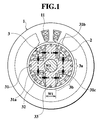
Fig. 1 is a cross sectional view of a permanent-magnet type rotating
machine for explanation of the 1st embodiment to the 3rd. embodiment of
the present invention, taken along the radial direction of the machine;
Fig. 2 is a cross sectional view of a rotor of Fig. 1 in the radial
direction of the machine, showing the flow of flux due to armature currents
in the component of directions along respective magnetic pole axes;
Fig. 3 is a cross sectional view of the rotor of Fig. 1 in the radial
direction of the machine, showing the flow of flux due to armature currents
in the component of directions along interpole center axes;
Fig. 4 is a cross sectional view of the rotor of Fig. 1 in the radial
direction of the machine, showing the flow of flux due to permanent
magnets in the rotor;
Fig. 5 is an explanatory cross sectional view of the rotor of the
permanent-magnet type rotating machine in accordance with the 4th.
embodiment of the present invention, taken along the radial direction of
the machine; and
Fig. 6 is a cross sectional view of the rotor of the permanent-magnet
type rotating machine in accordance with the 5th. embodiment of the
present invention, taken along the radial direction of the machine.
DESCRIPTION OF THE PREFERRED EMBODIMENT
Embodiments of the present invention will be described with reference
to Figs. 1 to 6, in detail.
Fig. 1 is a cross sectional view of a rotating machine in accordance
with the first embodiment of the present invention, taken along the radial
direction of the machine. In Fig. 1, a stator 1 includes armature windings
11 and is constructed so as to accommodates a rotor 3 therein through a
clearance (air gap) 2.
The rotor 3 includes a rotor core 31, permanent magnets 32 and
starting conductors (conductive bars) 33 both embedded in the rotor core
31. The rotor core 31 is constituted by a lamination of electromagnetic
steel plates each having eight cavities 31a formed along respective "easy-magnetizing"
directions to facilitate the rotor's magnetization, i.e., d-axes.
Eight cavities 31a are arranged crosswise in the rotor core 31. The
permanent magnets 32 are respectively embedded in these cavities 31a, so
that projecting poles and recessed portions are alternately arranged about
the rotor 3, providing four magnetic poles.
The permanent magnets 32 on both sides of each magnetic pole are
magnetized in the identical direction so as to negate the magnetic flux of
the armature windings 11 flowing along the adjoining recessed portions,
namely, "hard-magnetizing" directions (i.e. d-axes) in opposition to the
above easy-magnetizing directions. While, the permanent magnets 32 on
both sides of each recessed portion are magnetized in the opposite
directions to each other in the circumferential direction of the rotor core
31.
In other words, respective core portions each interposed between two
parallel cavities 31a provide magnetically projecting parts, i.e., respective
magnetic poles 3a extending in the easy-magnetizing directions, of a pole
width W1 each. On the other hand, respective core portions each
interposed between two perpendicularly adjoining cavities 31a provide
magnetically recessed parts, i.e., respective interpoles 3b extending in the
hard-magnetizing directions.
Recommended for the permanent magnets 32 are rare-earth permanent
magnets of high energy product, preferably, Nd-Fe-B permanent magnets
which are preferably magnetized in the generally-circumferential direction,
more preferably, in directions substantially perpendicular to the axes of the
magnetic poles 3a. In the rotor core 31, non-magnetic portions composed
of fan-shaped cavities 31c are formed in vicinity of the peripheries of the
interpoles 3b.
Further, the rotor core 31 has magnetic portions 31b each formed
between each magnetic pole 3a and the adjoining interpole 3b and also
between an outer end of the permanent magnet 32 and the peripheral face
of the rotor 3. The permanent magnets 32 are established so that the flux
density of the air gap 2 when the armature windings 11 are not excited is
less than e.g. 0.58 tesla (T).
According to the embodiment of the invention, since the permanent
magnets 32 are arranged sufficiently inside of the peripheral face of the
rotor core 31, the flux of each permanent magnet 32 also passes through
the magnetic portion 31b, so that the portion 31b is magnetically closed in
a short-circuit.
In order to provide the rotating machine capable of operating as one
induction machine at the machine's starting and also operating as one
synchronizing machine at the rated driving as the result of smooth "pull in"
for the synchronism, the first embodiment has the following establishment.
That is, the radial thickness of each magnetic portion 31b, the thickness
and surface area of each magnet 32 are respectively adjusted so that the
average of magnetic flux produced in the air gap 2 at the armature
windings' unexciting ranges from 0.1 [T] to 0.7 [T].
Simultaneously, the pole width W1 of the magnetic pole 3a and a width
W2 are established so that the ratio (Lq/Ld) of a self-inductance (Lq) of
the magnetic portion in the hard-magnetizing direction to a self-inductance
(Ld) in the easy-magnetizing direction ranges from 0.1 to 0.8. As shown
in Figs. 1 and 2, the width W2 corresponds to a width of the magnetic
portion 31b defined between the adjoining permanent magnets 32
interposing each interpole 3b on the side of the center of the rotor 3,
Next, we describe the operation of the rotor of the permanent magnet
type rotating machine in accordance with the first embodiment of the
invention with reference to Figs. 2 to 4. Note, in Fig. 2 and thereafter, the
above starting conductors (conductive bars) 33 arranged on the periphery
of the rotor core 31 are eliminated for facilitating the understanding for the
explanation.
That is, in Fig. 2, each magnetic flux ( d) designates a component of
flux due to the armature current of the d-axis, in the direction along the
pole 3a of the rotor core 31. Because of the magnetic path of each
magnetic pole 3a, the magnetic reluctance of the above flux ( d) is
extremely small, so that the magnetic flux can be produced with ease.
While, in Fig. 3, each magnetic flux ( q) designates a component of
flux due to the armature current of the q-axis, in the radial direction along
the interpole 3b of the rotor core 31. Although the magnetic flux ( q)
forms the magnetic path crossing the permanent magnets 32 in the
interpoles 3b, the flux by the armature current is deteriorated by the action
of high reluctance of the permanent magnets 32 because of its relative
permeability of approx. 1.
Therefore, as mentioned above, each permanent magnet 32 is
magnetized in the direction substantially perpendicular to the axis of the
pole 3a. Thus, as shown in Fig. 4, the flux flow starting from one pole of
one permanent magnet 32 passes in the following order: the magnetic
portion 31a on the boundary of the periphery of the rotor core 31 in the
circumferential direction, the magnetic pole 3a and the opposite pole of the
above permanent magnet 32, thereby forming a magnetic circuit ( ma).
While, the partial flux from one permanent magnet 32 also passes
through the following elements in order: the air gap 2, the not-shown stator
1 and the magnetic pole 3a of the rotor 3 (or the adjacent magnet 32) and
returns to the original magnet 32, forming a magnetic circuit ( mb).
Accordingly, as shown in Fig. 3, the interlinkage flux ( m) of the
permanent magnets 32 is distributed in the opposite direction to the
magnetic flux ( q) passing through the interpoles 3b toward the center of
the rotor 3 by the armature current of q-axis, so that the magnetic flux (
q) of the armature windings 11 entering through the interpoles 3b is
repelled for negation.
In the air gap 2 above the interpoles 3b, the flux density produced at
the gap 2 by the not-shown armature windings 11, namely, gap flux density
is reduced by the flux from the permanent magnets 32, producing a great
variation in comparison with the gap flux density above the poles 3a. In
this way, a large change in magnetic energy can be obtained by the change
in gap flux density with respect to the position of the rotor 3.
Further, the magnetic portions 31b of the rotor core 31, each of which
forms a short circuit between the pole 3a and the interpole 3b, are
magnetically saturated by load currents in case of the machine being
loaded, so that the magnetic flux of the magnets 32 distributed into the
interpoles 3b is increased. Therefore, since there can be produced an
unevenness in the distribution of gap flux density by the magnetic
reluctance and flux of the permanent magnets 32, the rotating machine is
capable of obtaining a great reluctance torque.
Meanwhile, it is noted that the reluctance torque originating in the
difference in magnetic energy between the pole 3a and the interpole 3b is a
sort of synchronous torque.
Further noted, the permanent magnet type rotating machine equipped
with the rotor of the embodiment operates as the induction machine at the
machine's starting and also as the synchronizing machine at the machine's
rated driving. Thus, in order to perform the machine's smooth shifting
from its induction drive to the synchronous drive, the synchronous torque
representing the reluctance torque as mentioned above is necessary.
Besides the reluctance torque, there exists a magnet torque which is
generated by the interaction between the flux of the permanent magnets 32
and the armature windings 11, in the synchronous torque. In order to
perform the above shifting from the induction to the synchronism
appropriately and smoothly, it is desirable to set the synchronous torque
large.
In order to enlarge the synchronous torque, it has only to increase the
magnet torque by reducing the width of the magnetic portion 31b between
the magnet end and the periphery of the rotor 3 for the magnetic saturation
in manner that the magnet flux rushes out into the gap 2. Alternatively, it
has only to increase the reluctance torque by increasing the pole width W1.
Also, it should be noted that the induction torque at the machine's
starting is generated by the armature current, in detail, a time change in
armature flux interlinking with the cage-shaped conductors on the outer
periphery of the rotor 3.
However, since the permanent magnets 32 disposed in the rotor 3 are
magnetized in the direction to negate the armature flux, the magnet flux
from the permanent magnets 32 operates in the direction to negate the time
change in armature flux interlinking with the cage-shaped conductors. In
other words, the flux of the permanent magnets 32 acts to reduce the
induction torque at the machine's starting.
In addition, if there exists a magnetic unevenness on the periphery of
the rotor 3, then the armature flux is difficult to generate because of
elevated magnetic reluctance in the hard-magnetizing direction (q-axis).
Consequently, the interlinkage flux with the conductors 33 is reduced to
deteriorate the starting torque.
Being eager to enter into the rotor core 31 through the only easy-magnetizing
direction (q-axis), the armature flux does cross with the
conductors 33 on the periphery of the rotor 3 partially, so that the starting
torque is influenced into reduction.
That is, in order to facilitate the machine's starting, it is desirable that
the magnet flux is small together with the magnetic unevenness. In this
way, the measures for facilitating the starting are contrary to the measures
for facilitating the synchronism.
In order to realize the rotating machine which is capable of operating as
the induction machine at the machine's starting and also as the
synchronizing machine at the machine's rated driving, the embodiments of
the invention do present the following conditions while providing the flux
of the permanent magnets and the magnetic unevenness with appropriate
values.
Thus, in the rotor of the permanent magnet type rotating machine of the
embodiment, the magnetic portion 31b is defined between the pole 3a and
the interpole 3b and between the end of the magnet 32 and the periphery of
the rotor core 31 so that the average of magnetic flux in the air gap 2,
which is produced by the permanent magnets 32 at the armature windings'
unexciting, ranges from 0.1 [T] to 0.7 [T]. Further, the rotor is also
constructed so as to provide the reluctance with more appropriate values
by changing the magnet flux and the pole width W1 respectively.
Preferably, the pole width W1 ranges from 0.3 to 0.5 times as long as
one pole pitch (i.e. a circumferential length from one center of one pole to
another center of the neighboring pole).
Further, the pole width W1 and the magnetic portion's width W2
between the adjoining magnets 32 are established so that the ratio (Lq/Ld)
of self-inductance (Lq) of the magnetic portion in the hard-magnetizing
direction to self inductance (Ld) in the easy-magnetizing direction, ranges
from 0.1 to 0.8.
With the above establishment, it is possible to realize the rotating
machine which can operate as the induction machine at the machine's
starting and also operate as the synchronous machine at the rated driving
owing to the smooth pull-in.
Next, we describe the rotor of the permanent magnet type rotating
machine in accordance with the 2nd. embodiment. Note, throughout the
respective embodiments mentioned later, there will be eliminated detailed
descriptions for constituents which are identical to those of the first
embodiment.
That is, the 2nd. embodiment mentioned below is on the assumption
that the rotor 3 is connected to the load substantially proportional to a
rotor's frequency to the power three. In the 1st. example, the rotor is
constructed in a manner that the resistivity of the conductors 33 on the
periphery of the rotor 3 substantially equals to the resistivity of aluminum.
Further, in the 1st. example, the magnetic portion 31b is defined
between the pole 3a and the interpole 3b and between the end of the
magnet 32 and the periphery of the rotor core 31 so that the average of
magnetic flux produced by the permanent magnets 32 at the armature
windings' unexciting, ranges from 0.1 [T] to 0.5 [T] in the air gap 2. The
pole width W1 and the width W2 of the magnetic portion between the
adjoining magnets 32 are established so that the ratio (Lq/Ld) of self-inductance
(Lq) of the magnetic portion in the hard-magnetizing direction
to self-inductance (Ld) in the easy-magnetizing direction, ranges from 0.1
to 0.8.
In the 2nd. example, the resistivity of the conductors 33 is equal to
general 110 % with respect to the resistivity of aluminum. Then, the
magnetic portion 31b, the pole width W1 and the width W2 are
respectively established so that the average of magnetic flux produced by
the permanent magnets 32 at the armature windings' unexciting, ranges
from 0.2 [T] to 0.6 [T] in the air gap 2 and the ratio (Lq/Ld) of self-inductance
in the hard-magnetizing direction to self-inductance in the
easy-magnetizing direction ranges from 0.1 to 0.7.
In the 3rd. example, the resistivity of the conductors 33 is equal to
general 120 % with respect to the resistivity of aluminum. Then, the
magnetic portion 31b, the pole width W1 and the width W2 are
respectively established so that the average of magnetic flux produced by
the permanent magnets 32 at the armature windings' unexciting, ranges
from 0.2 [T] to 0.6 [T] in the air gap 2, and the ratio (Lq/Ld) of self-inductance
in the hard-magnetizing direction to self-inductance in the
easy-magnetizing direction ranges from 0.1 to 0.6.
In the 4th. example, the resistivity of the conductors 33 is equal to
general 130 % with respect to the resistivity of aluminum. Then, the
magnetic portion 31b, the pole width W1 and the width W2 are
respectively established so that the average of magnetic flux produced by
the permanent magnets 32 at the armature windings' unexciting, ranges
from 0.2 [T] to 0.6 [T] in the air gap 2, and the ratio (Lq/Ld) of self-inductance
in the hard-magnetizing direction to self-inductance in the
easy-magnetizing direction ranges from 0.1 to 0.5.
In the 5th. example, the resistivity of the conductors 33 is equal to
general 140 % with respect to the resistivity of aluminum. Then, the
magnetic portion 31b, the pole width W1 and the width W2 are
respectively established so that the average of magnetic flux produced by
the permanent magnets 32 at the armature windings' unexciting, ranges
from 0.3 [T] to 0.6 [T] in the air gap 2, and the ratio (Lq/Ld) of self-inductance
in the hard-magnetizing direction to self-inductance in the
easy-magnetizing direction ranges from 0.1 to 0.5.
In the 6th. example, the resistivity of the conductors 33 is equal to
general 150 % with respect to the resistivity of aluminum. Then, the
magnetic portion 31b, the pole width W1 and the width W2 are
respectively established so that the average of magnetic flux produced by
the permanent magnets 32 at the armature windings' unexciting, ranges
from 0.3 [T] to 0.7 [T] in the air gap 2, and the ratio (Lq/Ld) of self-inductance
in the hard-magnetizing direction to self-inductance in the
easy-magnetizing direction ranges from 0.1 to 0.4.
Next, we describe the 3rd. embodiment of the invention. In this
embodiment, the rotor is driven under no load, i.e. substantial "zero" from
the machine's starting to synchronism. After reaching the rated rotations,
the rotor is connected to the load substantially proportional to a rotor's
frequency to the power three.
Under the condition, in the 1st. example, the resistivity of the
conductors 33 on the periphery of the rotor 3 is substantially equal to the
resistivity of aluminum. Further, the magnetic portion 31b is defined so
that the average of magnetic flux produced by the permanent magnets 32 at
the armature windings' unexciting ranges from 0.1 [T] to 0.5 [T] in the air
gap 2, while the magnet flux and the reluctance are established so as to
have appropriate values, respectively.
The pole width W1 and the width W2 of the magnetic portion between
the adjoining magnets 32 are established so that the ratio (Lq/Ld) of self-inductance
(Lq) of the magnetic portion in the hard-magnetizing direction
to self-inductance (Ld) in the easy-magnetizing direction, ranges from 0.1
to 0.8. Consequently, there can be provided a rotating machine which
operates as the induction machine at the machine's starting and also
operates as the synchronous machine at the rated driving, smoothly.
In the 2nd. example, the resistivity of the conductors 33 is equal to
general 110 % with respect to the resistivity of aluminum. Then, the
magnetic portion 31b, the pole width W1 and the width W2 are
respectively established so that the average of magnetic flux produced by
the permanent magnets 32 at the armature windings' unexciting, ranges
from 0.2 [T] to 0.6 [T] in the air gap 2 and the ratio (Lq/Ld) of self-inductance
in the hard-magnetizing direction to self-inductance in the
easy-magnetizing direction ranges from 0.1 to 0.7.
In the 3rd. example, the resistivity of the conductors 33 is equal to
general 120 % with respect to the resistivity of aluminum. Then, the
magnetic portion 31b, the pole width W1 and the width W2 are
respectively established so that the average of magnetic flux produced by
the permanent magnets 32 at the armature windings' unexciting, ranges
from 0.2 [T] to 0.6 [T] in the air gap 2, and the ratio (Lq/Ld) of self-inductance
in the hard-magnetizing direction to self-inductance in the
easy-magnetizing direction ranges from 0.1 to 0.6.
In the 4th. example, the resistivity of the conductors 33 is equal to
general 130 % with respect to the resistivity of aluminum. Then, the
magnetic portion 31b, the pole width W1 and the width W2 are
respectively established so that the average of magnetic flux produced by
the permanent magnets 32 at the armature windings' unexciting, ranges
from 0.2 [T] to 0.6 [T] in the air gap 2, and the ratio (Lq/Ld) of self-inductance
in the hard-magnetizing direction to self-inductance in the
easy-magnetizing direction ranges from 0.1 to 0.5.
In the 5th. example, the resistivity of the conductors 33 is equal to
general 140 % with respect to the resistivity of aluminum. Then, the
magnetic portion 31b, the pole width W1 and the width W2 are
respectively established so that the average of magnetic flux produced by
the permanent magnets 32 at the armature windings' unexciting, ranges
from 0.3 [T] to 0.6 [T] in the air gap 2, and the ratio (Lq/Ld) of self-inductance
in the hard-magnetizing direction to self-inductance in the
easy-magnetizing direction ranges from 0.1 to 0.5.
In the 6th. example, the resistivity of the conductors 33 is equal to
general 150 % with respect to the resistivity of aluminum. Then, the
magnetic portion 31b, the pole width W1 and the width W2 are
respectively established so that the average of magnetic flux produced by
the permanent magnets 32 at the armature windings' unexciting, ranges
from 0.3 [T] to 0.7 [T] in the air gap 2, and the ratio (Lq/Ld) of self-inductance
in the hard-magnetizing direction to self-inductance in the
easy-magnetizing direction ranges from 0.1 to 0.4.
On the ground that the rotor is driven under no load, i.e. substantial
"zero" from the machine's starting to synchronism and, after reaching the
rated rotations, the rotor is connected to the load substantially proportional
to a rotor's frequency to the power three, owing to the establishment of:
resistivity of the conductors 33; average of magnetic flux produced by the
permanent magnets 32 at the armature windings' unexciting; and ratio
(Lq/Ld) of self-inductance in the hard-magnetizing direction to self-inductance
in the easy-magnetizing direction, it is possible to provide a
rotating machine which operates as the induction machine at the machine's
starting and also operates as the synchronous machine at the rated driving,
smoothly.
Fig. 5 is a cross sectional view of the rotor of the permanent-magnet
type rotating machine in accordance with the 4th. embodiment of the
present invention, taken along the radial direction of the machine.
According to the embodiment, the conductors (conductive bars) 33 are
arranged in the periphery of the rotor core 31 in the circumferential
direction. As shown in the figure, each conductor 33 is shaped to have an
oblong cross section characterized by sufficiently long sides in comparison
with the other sides. In arrangement, the conductors 33 are arranged
radially of the rotational center axis of the rotor core 31 as a center in a
manner that the respective long sides of the cross sections extend along the
radial direction of the rotor 3.
Although the induction torque at the machine's starting is proportional
to the time variation rate of interlinkage flux of the armature windings 11
with the starting conductors 33 and also the resistance of conductor 33, the
flux does not enter the interior of rotor core more than the surface of the
rotor by the skin effect of alternating flux since the flux of high frequency
is produced at the machine's starting.
Therefore, since the cross section of the conductor 33 is shaped long in
the radial direction of the rotor 3 and short in the circumferential direction,
the induction current flows through the only outer ends of the conductors
33 by the skin effect, which is equivalent to a case of reducing the cross
sections of the conductors 33. In other words, the rotor 3 having the so-shaped
conductors 33 is equivalent to a condition of elevating the
resistance of each conductor 33, so that it is possible to generate the
starting torque effectively.
Additionally, because of its narrowness of each conductor 33 in the
circumferential direction of the rotor 3, the magnetic path in each pole 3a
is so broadened to facilitate the flow of flux in the easy-magnetizing
direction (d-axis) furthermore, causing the reluctance torque to be
increased. Consequently, owing to the starting torque which is effectively
ensured at the machine's starting and the reluctance torque which is
effectively generated at the machine's rated driving, it is possible to realize
a rotating machine which operates as the induction machine at the
machine's starting and also operates as the synchronous machine at the
rated driving.
Fig. 6 is a cross sectional view of the rotor of the permanent-magnet
type rotating machine in accordance with the 5th. embodiment of the
present invention, taken along the radial direction of the machine.
According to the embodiment, the rotor core 31 is provided, on the
peripheral part, with the conductors 33 which can generate the induced
current at the machine's starting to ensure the starting torque. As shown
in the figure, each conductor 33 has a cross section in the form of an
isosceles triangle of which the base is arranged on the side of the periphery
of the rotor core 31 while the peak directs to the side of the center axis of
the rotor core 31. These conductors 33 are arranged radially of the
rotational center axis of the rotor core 31 as a center.
Note, the width of the isosceles triangular conductor's part in the
circumferential direction of the rotor 3 gets larger as the part approaches
the base. That is, by positioning each conductor's base of the largest
width on the outer peripheral portion of the rotor 3 having a cicumferential
length in comparison with that of the inner peripheral portion, it is possible
to ensure a magnetic path in the easy-magnetizing direction, which is
broader than that in case of arranging each conductor's base on the inner
peripheral side of the rotor core 31, thereby increasing the reluctance
torque.
Furthermore, since the starting torque is generated by the starting
current induced in the conductors 33 at the machine's starting and the large
reluctance torque can be obtained at the machine's rated driving, it is
possible to realize a rotating machine which can transfer from its operation
as the induction machine at the machine's starting to the operation as the
synchronous machine at the rated driving, smoothly.
As mentioned above, owing to the establishment of: pole width, width
of magnetic portion between the adjoining magnets, magnet flux, ratio of
self-inductance of the magnetic portion in the hard-magnetizing direction
to self-inductance in the easy-magnetizing direction, and configurations of
conductors (i.e. excessive oblong, isosceles triangle), the rotor of the
permanent magnet type rotating machine is capable of smooth pull-in for
the machine's synchronism thereby to provide a great effect for practical
use.
Finally, it will be understood by those skilled in the art that the
foregoing descriptions are preferred embodiments of the rotating machine,
and that various changes and modifications may be made to the present
invention without departing from the spirit and scope thereof.