EP1043530A2 - Druckluftversorgungssytem - Google Patents
Druckluftversorgungssytem Download PDFInfo
- Publication number
- EP1043530A2 EP1043530A2 EP00107448A EP00107448A EP1043530A2 EP 1043530 A2 EP1043530 A2 EP 1043530A2 EP 00107448 A EP00107448 A EP 00107448A EP 00107448 A EP00107448 A EP 00107448A EP 1043530 A2 EP1043530 A2 EP 1043530A2
- Authority
- EP
- European Patent Office
- Prior art keywords
- compressed air
- supply system
- air supply
- carrier
- air hose
- Prior art date
- Legal status (The legal status is an assumption and is not a legal conclusion. Google has not performed a legal analysis and makes no representation as to the accuracy of the status listed.)
- Granted
Links
Images

Classifications
-
- F—MECHANICAL ENGINEERING; LIGHTING; HEATING; WEAPONS; BLASTING
- F16—ENGINEERING ELEMENTS AND UNITS; GENERAL MEASURES FOR PRODUCING AND MAINTAINING EFFECTIVE FUNCTIONING OF MACHINES OR INSTALLATIONS; THERMAL INSULATION IN GENERAL
- F16L—PIPES; JOINTS OR FITTINGS FOR PIPES; SUPPORTS FOR PIPES, CABLES OR PROTECTIVE TUBING; MEANS FOR THERMAL INSULATION IN GENERAL
- F16L3/00—Supports for pipes, cables or protective tubing, e.g. hangers, holders, clamps, cleats, clips, brackets
- F16L3/01—Supports for pipes, cables or protective tubing, e.g. hangers, holders, clamps, cleats, clips, brackets for supporting or guiding the pipes, cables or protective tubing, between relatively movable points, e.g. movable channels
Definitions
- the present invention relates to a compressed air supply system a compressed air carrier for distributing compressed air to several consumers, with a linearly arranged, at least one consumer holding carriage, and with a connectable to the compressed air carrier, compressed air hose guided in a guide element, the Compressed air hose up to the end connected to the compressed air carrier is linearly movable together with the carriage.
- Compressed air supply systems of this type are used, for example Conveyor belts used by the automaker, the particular as Pneumatic screwdriver trained consumers above the respective assembly site is hanging and linearly arranged. If necessary, the Consumers are carried in the direction of the assembly line (and back). The freedom of movement of the worker, i.e. of the consumer is through the Length and arrangement of the compressed air hose connected to it limited.
- compressed air distribution systems with the entrance mentioned features offered, in which the compressed air hose in an energy chain is introduced and together with this in Guide element is moved linearly.
- the one in the energy chain Compressed air hose is protected against kinking and is protected by the Reliably move the energy chain in the guide element without the Compressed air hose pops out in an undesirable manner.
- the present invention is based on the object to create a compressed air supply system which is inexpensive to manufacture and is to be assembled and yet a great freedom of movement of the Worker, as well as a high energy or compressed air transport.
- the present invention is based on the finding that the supporting parts of the compressed air supply system smaller and cheaper can be interpreted if its own weight is reduced becomes. This also leads to a simpler and therefore less expensive Assembly.
- the invention proposes the above-mentioned compressed air supply system to further develop that at least a part of the compressed air hose sliding in Guide element is held.
- a compressed air supply system designed according to this technical teaching has the advantage that an energy chain can be dispensed with, which leads to a considerable weight and cost reduction, because on the one hand, the costs for the energy chain are eliminated and, on the other hand, the supporting parts of the compressed air supply system due to the elimination can be dimensioned smaller according to the energy chain. On due to the elimination of the energy chain, a smaller guide element reinforces this effect.
- Another advantage is that by eliminating the energy chain with the same guide element, more space is available in it, so that a thicker compressed air hose can be used if necessary. This has the advantage that more energy in the form of Compressed air is available and that the occurring in the hose Friction losses can be reduced.
- the surface of the compressed air hose is made of nylon, perlon, polypropylene, polyester, teflon, kevlar, Polyurethane or a combination of at least two of the aforementioned Materials trained. These materials have the advantage that the Frictional resistance of the compressed air hose lowers what the sliding of the Favored hose in the guide element.
- this effect is achieved through training a profiled surface of the compressed air hose is reinforced, especially if a net-like stocking is over the compressed air hose is covered. Due to the low-resistance sliding of the compressed air hose preferably in a throat of the guide element simply move the compressed air hose up to 20 meters long enables, without the compressed air hose forming waves, canting or out of the guide.
- the compressed air carrier trained self-supporting.
- the compressed air carrier is preferably dimensioned so that it has only a few suspension points on the ceiling of the Factory hall or the like can be attached and the rest even carries. This makes a complex support structure superfluous, which leads to a further cost reduction.
- Another advantage is that the self-supporting compressed air carrier a compressed air duct so large that it can be used as a storage for the compressed air. On the one hand, this becomes a complex storage boiler superfluous and on the other hand, the pressure losses in the compressed air supply system minimized because the pressure drops with increasing diameter of the compressed air duct and since the storage is much closer is arranged on the consumer so that large transmission paths are eliminated.
- the cross section of the compressed air channel is advantageously round trained, as this further minimizes the friction losses.
- a is on the compressed air carrier C-, T-, U- or I-shaped holding profile for slidably holding the Fixed sled.
- This holding profile has its own, not insignificant rigidity.
- this is Guide element designed as a C- or U-shaped profile. This has the Advantage that the guide element is simple and inexpensive to manufacture can be, especially if this is preferably folded from sheet metal or bent.
- Compressed air carriers are provided at certain intervals from each other, which can be locked individually. This allows individual pressure hoses quickly and easily removed from the system and be attached to another transfer valve. Is too this makes it possible quickly on the compressed air hose and on the transfer valve and easy to remove couplings, so that the displacement of the Compressed air hose becomes even easier.
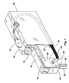
- the compressed air supply system shown in Figures 1 to 3 is used for example in assembly line workplaces to supply compressed air for the To provide drills, screwdrivers or other applications.
- Such Systems are usually placed around the work place to give the worker the greatest possible freedom of movement. That counts also that the tool not shown here along the Assembly line can be carried.
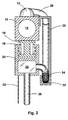
- the compressed air supply system shown here includes one Compressed air carrier 10 made of a continuously cast aluminum profile, on its Transfer valves 12 are arranged at the top at regular intervals.
- the compressed air carrier 10 has the actual compressed air inside leading and designed as a round bore channel 14 due to its size also at least partially the function of a Compressed air storage takes over.
- These compressed air carriers 10 are up to eight Meters long and have an edge length of 6 cm to 15 cm, at one Inner diameter of the channel 14 from 5 cm to 14 cm.
- the single ones Compressed air carriers 10 are pressure-tight via known O-rings interconnected and can be used in any way along the Assembly line.
- the compressed air carrier 10 are due to their Dimensioning and design as an aluminum profile, self-supporting and can be hung at a few attachment points, for example under the Hall ceiling are hung, so that the usual support structure not applicable. Due to the very large channel 14, a large part of the required compressed air can be stored here, so that otherwise Usual compressed air storage is also eliminated and the compressed air on site is saved and is available here.
- An I-shaped holding profile 16 is attached under the compressed air carrier 10, in which a carriage 20 provided with rollers 18 is linearly displaceable is held.
- a support cable 22 is attached to the slide 20, which the consumer, not shown here, especially a screwdriver hanging.
- the carriage 20 comprises a hollow chamber profile 24 on which A compressed air hose 26 leading to the consumer on the outlet side is connected and on the input side one of the compressed air carrier 10 Coming compressed air hose 28 arrives.
- This compressed air hose 28 is on the one hand on the transfer valve 12 and on the other hand docked on the hollow chamber profile 24.
- this compressed air hose 28 is 6 meters long and allowed so the carriage 20 has a maximum mobility of 12 meters, i.e. 6 Meters forward and 6 meters back.
- this is in one Guide element 30 guided such that the compressed air hose 28 in a Throat 32 of the guide member 30 is located.
- This C-shaped sheet metal Guide element 30 is attached to the side of the compressed air carrier 10 and also extends almost over the entire length of the compressed air carrier 10.
- Compressed air hose 28 comes from above a half loop is laid and lies with its lower area in the throat 32 on. At the end of the compressed air hose 28, this is again from the Throat 32 led out and inserted into the hollow chamber profile 24, wherein the connection to the hollow chamber profile is arranged above the throat 32 is.
- the compressed air hose 28 is covered with a net-like nylon stocking 34, to the frictional resistance of the compressed air hose to be guided on the sheet 28 to reduce.
- This makes it possible that the Consumer working person progressing along the assembly line carries the consumer with him and over the connected suspension cable 22nd moved the carriage 20 with. This is connected to the carriage 20
- Compressed air hose 28 moves linearly in the same direction and shifts the part of the compressed air hose lying in the throat accordingly 28. Depending on the direction of movement, this becomes the half-loop enlarged or reduced, but in any case the compressed air hose 28 guided precisely and reliably. It has proven to be beneficial proven to perform the guide member 30 at least as high as the permissible bending radius of the compressed air hose 28 requires it.
- the Net stocking 34 also through a profile on the surface of the compressed air hose 28 to be replaced. It would also be possible to change the surface of the Compressed air hose 28 particularly through a suitable choice of material to train with little friction. This can be done, for example, by using Nylon, Perlon, Kevlar, Teflon, Polypropylene, Polyurethane or one Combination of this happen.
- a is in the transfer valve Ball valve provided, with which the transfer valve individually shut off can be.
- the pressure hose is by means of a Quick coupling can be connected to the transfer valve, so that the hose with can be docked and undocked with one hand.
Landscapes
- Engineering & Computer Science (AREA)
- General Engineering & Computer Science (AREA)
- Mechanical Engineering (AREA)
- Rigid Pipes And Flexible Pipes (AREA)
- Compressors, Vaccum Pumps And Other Relevant Systems (AREA)
- Actuator (AREA)
- Folding Of Thin Sheet-Like Materials, Special Discharging Devices, And Others (AREA)
- Braiding, Manufacturing Of Bobbin-Net Or Lace, And Manufacturing Of Nets By Knotting (AREA)
- Saccharide Compounds (AREA)
- Medicines That Contain Protein Lipid Enzymes And Other Medicines (AREA)
Abstract
Description
- Fig. 1
- eine perspektivische Ansicht eines Ausschnitt des Druckluftversorgungssystems;
- Fig. 2
- eine geschnitten dargestellte Frontansicht des Druckluftversorgungssystems gemäß Fig. 1, geschnitten entlang Linie II - II in Fig. 1;
- Fig. 3
- eine vergrößerte Darstellung des Druckluftschlauches des Druckluftversorgungssystems gemäß Fig. 1.
- 10
- Druckluftträger
- 12
- Übergabeventil
- 14
- Kanal
- 16
- Halteprofil
- 18
- Rollen
- 20
- Schlitten
- 22
- Trageseil
- 24
- Hohlkammerprofil
- 26
- Druckluftschlauch
- 28
- Druckluftschlauch
- 30
- Führungselement
- 32
- Kehle
- 34
- Netzstrumpf
Claims (10)
- Druckluftversorgungssystem mit einem Druckluftträger (10) zur Verteilung von Druckluft an mehrere Verbraucher, mit einem linear verfahrbar angeordneten, mindestens einen Verbraucher haltenden Schlitten (20), und mit einem an dem Drucklufträger (10) anschließbaren, in einem Führungselement (30) geführten Druckluftschlauch (28), wobei der Druckluftschlauch (28) bis auf das an dem Druckluftträger (10) angeschlossene Ende zusammen mit dem Schlitten (20) linear verfahrbar ist,
dadurch gekennzeichnet,
dass zumindest ein Teil des Druckluftschlauches (28) gleitend im Führungselement (30) gehalten ist. - Druckluftversorgungssystem nach Anspruch 1,
dadurch gekennzeichnet,
dass der Druckluftschlauch (28) eine Oberfläche aus Nylon, Perlon, Polypropylän, Teflon, Polyester, Kevlar, Polyurethan oder aus einer Kombination wenigstens zwei der vorgenannten Materialien aufweist. - Druckluftversorgungssystem nach einem der vorangehenden
Ansprüche,
dadurch gekennzeichnet, dass der Druckluftschlauch (28) eine profilierte Oberfläche aufweist. - Druckluftversorgungssystem nach einem der vorangehenden Ansprüche,
dadurch gekennzeichnet,
dass der Druckluftschlauch (28) mit einem netzartigen Strumpf (34) überzogen ist. - Druckluftversorgungssystem nach einem der vorangehenden Ansprüche,
dadurch gekennzeichnet,
dass der Druckluftträger (10) selbsttragend ausgebildet ist. - Druckluftversorgzungssystem nach einem der vorangehenden Ansprüche,
dadurch gekennzeichnet,
dass im Druckluftträger (10) ein im Querschnitt runder Kanal (14) ausgebildet ist. - Druckluftversorgungssystem nach einem der vorangehenden Ansprüche,
dadurch gekennzeichnet,
dass am Druckluftträger (10) ein C-, T-, U- oder I-förmiges Halteprofil (16) zur verschiebbaren Aufnahme des Schlittens (20) befestigt ist. - Druckluftversorgungssystem nach einem der vorangehenden Ansprüche,
dadurch gekennzeichnet,
dass das Führungselement (30) als C- oder U-förmiges Profil ausgebildet ist. - Druckluftversorgungssystem nach einem der vorangehenden Ansprüche,
dadurch gekennzeichnet,
dass das Führungselement (30) aus einem Blech gefalzt oder gebogen ist. - Druckluftversorgungssystem nach einem der vorangehenden Ansprüche,
dadurch gekennzeichnet,
dass am Druckluftträger (10) in bestimmten Abständen voneinander Übergabeventile (12) vorgesehen sind, die einzeln absperrbar sind.
Priority Applications (1)
| Application Number | Priority Date | Filing Date | Title |
|---|---|---|---|
| DE20017399U DE20017399U1 (de) | 1999-04-10 | 2000-04-06 | Druckluftversorgungssystem |
Applications Claiming Priority (2)
| Application Number | Priority Date | Filing Date | Title |
|---|---|---|---|
| DE19916184 | 1999-04-10 | ||
| DE19916184A DE19916184C2 (de) | 1999-04-10 | 1999-04-10 | Druckluftversorgungssystem |
Publications (4)
| Publication Number | Publication Date |
|---|---|
| EP1043530A2 true EP1043530A2 (de) | 2000-10-11 |
| EP1043530A3 EP1043530A3 (de) | 2001-10-04 |
| EP1043530B1 EP1043530B1 (de) | 2005-06-08 |
| EP1043530B2 EP1043530B2 (de) | 2009-09-02 |
Family
ID=7904112
Family Applications (1)
| Application Number | Title | Priority Date | Filing Date |
|---|---|---|---|
| EP00107448A Expired - Lifetime EP1043530B2 (de) | 1999-04-10 | 2000-04-06 | Druckluftversorgungssytem |
Country Status (3)
| Country | Link |
|---|---|
| EP (1) | EP1043530B2 (de) |
| AT (1) | ATE297522T1 (de) |
| DE (2) | DE19916184C2 (de) |
Cited By (1)
| Publication number | Priority date | Publication date | Assignee | Title |
|---|---|---|---|---|
| EP1588807A1 (de) * | 2004-04-23 | 2005-10-26 | KUKA Roboter GmbH | Führen flexibler Elemente entlang beweglicher Maschinenteile und Befestigen von Maschinenanbauten |
Family Cites Families (9)
| Publication number | Priority date | Publication date | Assignee | Title |
|---|---|---|---|---|
| GB725156A (en) * | 1953-01-27 | 1955-03-02 | British Oxygen Co Ltd | Means for controlling the movement of a looped hose, electric cable, or like flexible element |
| US2720217A (en) * | 1954-11-24 | 1955-10-11 | William J H Vossbrinck | Compressed air transmission system for pneumatic tools |
| GB819862A (en) * | 1954-12-15 | 1959-09-09 | Hancock & Co Eng Ltd | Improvements in or relating to supply tube and electric cable handling devices |
| US3014494A (en) * | 1959-02-24 | 1961-12-26 | Acme Steel Co | Tool mount |
| DE3433602A1 (de) * | 1984-08-18 | 1986-02-27 | Horst 7447 Aichtal Jentzsch | Einrichtung zum absaugen und sammeln von gasen, insbesondere von kraftfahrzeug-auspuffgasen in einer montage- oder betriebshalle |
| DE9016870U1 (de) * | 1990-12-13 | 1992-04-16 | W.L. Gore & Associates Gmbh, 8011 Putzbrunn | Leitungsführungsanordnung |
| DE9208885U1 (de) * | 1992-07-03 | 1992-10-01 | Rinke Druckluft GmbH Entwicklung-Montagetechnik, 3513 Staufenberg | Druckluft-Verteileinrichtung |
| DE4444280C2 (de) * | 1994-12-13 | 1996-10-02 | Hennecke Gmbh Maschf | Verfahren und Vorrichtung zur Energieversorgung von an einer Kette umlaufenden Arbeitsstationen |
| DE29802278U1 (de) † | 1998-02-11 | 1999-06-10 | Wampfler AG, 79576 Weil am Rhein | Arbeitsplatz-Versorgungsvorrichtung |
-
1999
- 1999-04-10 DE DE19916184A patent/DE19916184C2/de not_active Revoked
-
2000
- 2000-04-06 EP EP00107448A patent/EP1043530B2/de not_active Expired - Lifetime
- 2000-04-06 AT AT00107448T patent/ATE297522T1/de not_active IP Right Cessation
- 2000-04-06 DE DE50010490T patent/DE50010490D1/de not_active Expired - Lifetime
Cited By (2)
| Publication number | Priority date | Publication date | Assignee | Title |
|---|---|---|---|---|
| EP1588807A1 (de) * | 2004-04-23 | 2005-10-26 | KUKA Roboter GmbH | Führen flexibler Elemente entlang beweglicher Maschinenteile und Befestigen von Maschinenanbauten |
| US7520473B2 (en) | 2004-04-23 | 2009-04-21 | Kuka Roboter Gmbh | Device for guiding flexible elements along movable machine parts |
Also Published As
| Publication number | Publication date |
|---|---|
| DE19916184A1 (de) | 2000-10-19 |
| EP1043530B1 (de) | 2005-06-08 |
| DE19916184C2 (de) | 2001-05-17 |
| EP1043530B2 (de) | 2009-09-02 |
| EP1043530A3 (de) | 2001-10-04 |
| DE50010490D1 (de) | 2005-07-14 |
| ATE297522T1 (de) | 2005-06-15 |
Similar Documents
| Publication | Publication Date | Title |
|---|---|---|
| EP0210271B1 (de) | Biegbares wellrohr mit zueinander parallelen, ringförmigen wellen und axialabstützung | |
| EP3112098B1 (de) | Vorrichtung zur führung von zumindest einer leitung eines gelenkarmroboters sowie gelenkarmroboter | |
| AT506686A1 (de) | Kabelführungselement | |
| DE102008002926B3 (de) | Vorrichtung zum Verbinden von axialen Längenänderungen unterworfenen Rohrleitungen | |
| DE3910757C2 (de) | ||
| DE102007018543B4 (de) | Vorrichtung zum Führen von Versorgungsleitungen entlang der Struktur eines Industrieroboters | |
| DE1599041C2 (de) | Vorrichtung zur Führung flexibler Versorgungsleitungen in Röntgenanlagen | |
| DE202016106401U1 (de) | Leitungsführungseinrichtung und Andockstation | |
| DE102008041230A1 (de) | Halter zur Befestigung mindestens einer Leitung | |
| WO2008071617A2 (de) | Linearführungsmodul umfassend einen führungswagen | |
| DE102009037515B4 (de) | Vorrichtung und Verfahren zum Führen von Versorgungsleitungen an einem Gelenkroboter | |
| EP2643248B1 (de) | Fördersystem, förderelement und führungsbahn | |
| DE19916184C2 (de) | Druckluftversorgungssystem | |
| DE102009037517A1 (de) | Vorrichtung und Verfahren zum Führen von Versorgungsleitungen an einem Industrieroboter | |
| DE102010012535B4 (de) | Kugelgelagerte Führungseinrichtung mit einstellbarer Vorspannung | |
| EP3737625B1 (de) | Förderband-abstreifvorrichtung und verschiebeführung dafür | |
| DE202004018318U1 (de) | Schutzabdeckung | |
| DE102007015407B3 (de) | Anschlussvorrichtung für eine Fluidleitung | |
| AT513330A1 (de) | Dämpfvorrichtung für bewegbare Möbelteile | |
| DE20017399U1 (de) | Druckluftversorgungssystem | |
| DE102007018163A1 (de) | Spreizbandmechanik mit Rollenführung | |
| DE102011114697A1 (de) | Schutzabdeckung mit Schmierung | |
| DE102010060475A1 (de) | Anschlagmittel und ein solches Anschlagmittel umfassende Vorrichtung zum Heben von schweren Lasten | |
| EP1188693B1 (de) | Kettentragelement für ein Transfersystem | |
| DE102015003192A1 (de) | Zugentlastungselement für Energieführungsketten |
Legal Events
| Date | Code | Title | Description |
|---|---|---|---|
| PUAI | Public reference made under article 153(3) epc to a published international application that has entered the european phase |
Free format text: ORIGINAL CODE: 0009012 |
|
| AK | Designated contracting states |
Kind code of ref document: A2 Designated state(s): AT BE CH CY DE DK ES FI FR GB GR IE IT LI LU MC NL PT SE |
|
| AX | Request for extension of the european patent |
Free format text: AL;LT;LV;MK;RO;SI |
|
| PUAL | Search report despatched |
Free format text: ORIGINAL CODE: 0009013 |
|
| AK | Designated contracting states |
Kind code of ref document: A3 Designated state(s): AT BE CH CY DE DK ES FI FR GB GR IE IT LI LU MC NL PT SE |
|
| AX | Request for extension of the european patent |
Free format text: AL;LT;LV;MK;RO;SI |
|
| 17P | Request for examination filed |
Effective date: 20020328 |
|
| AKX | Designation fees paid |
Free format text: AT BE CH CY DE DK ES FI FR GB GR IE IT LI LU MC NL PT SE |
|
| 17Q | First examination report despatched |
Effective date: 20030613 |
|
| GRAP | Despatch of communication of intention to grant a patent |
Free format text: ORIGINAL CODE: EPIDOSNIGR1 |
|
| GRAS | Grant fee paid |
Free format text: ORIGINAL CODE: EPIDOSNIGR3 |
|
| GRAA | (expected) grant |
Free format text: ORIGINAL CODE: 0009210 |
|
| AK | Designated contracting states |
Kind code of ref document: B1 Designated state(s): AT BE CH CY DE DK ES FI FR GB GR IE IT LI LU MC NL PT SE |
|
| PG25 | Lapsed in a contracting state [announced via postgrant information from national office to epo] |
Ref country code: IT Free format text: LAPSE BECAUSE OF FAILURE TO SUBMIT A TRANSLATION OF THE DESCRIPTION OR TO PAY THE FEE WITHIN THE PRESCRIBED TIME-LIMIT;WARNING: LAPSES OF ITALIAN PATENTS WITH EFFECTIVE DATE BEFORE 2007 MAY HAVE OCCURRED AT ANY TIME BEFORE 2007. THE CORRECT EFFECTIVE DATE MAY BE DIFFERENT FROM THE ONE RECORDED. Effective date: 20050608 Ref country code: FI Free format text: LAPSE BECAUSE OF FAILURE TO SUBMIT A TRANSLATION OF THE DESCRIPTION OR TO PAY THE FEE WITHIN THE PRESCRIBED TIME-LIMIT Effective date: 20050608 Ref country code: IE Free format text: LAPSE BECAUSE OF FAILURE TO SUBMIT A TRANSLATION OF THE DESCRIPTION OR TO PAY THE FEE WITHIN THE PRESCRIBED TIME-LIMIT Effective date: 20050608 Ref country code: NL Free format text: LAPSE BECAUSE OF FAILURE TO SUBMIT A TRANSLATION OF THE DESCRIPTION OR TO PAY THE FEE WITHIN THE PRESCRIBED TIME-LIMIT Effective date: 20050608 |
|
| REG | Reference to a national code |
Ref country code: GB Ref legal event code: FG4D Free format text: NOT ENGLISH |
|
| REG | Reference to a national code |
Ref country code: CH Ref legal event code: EP |
|
| GBT | Gb: translation of ep patent filed (gb section 77(6)(a)/1977) |
Effective date: 20050608 |
|
| REF | Corresponds to: |
Ref document number: 50010490 Country of ref document: DE Date of ref document: 20050714 Kind code of ref document: P |
|
| REG | Reference to a national code |
Ref country code: IE Ref legal event code: FG4D Free format text: LANGUAGE OF EP DOCUMENT: GERMAN |
|
| PG25 | Lapsed in a contracting state [announced via postgrant information from national office to epo] |
Ref country code: DK Free format text: LAPSE BECAUSE OF FAILURE TO SUBMIT A TRANSLATION OF THE DESCRIPTION OR TO PAY THE FEE WITHIN THE PRESCRIBED TIME-LIMIT Effective date: 20050908 Ref country code: SE Free format text: LAPSE BECAUSE OF FAILURE TO SUBMIT A TRANSLATION OF THE DESCRIPTION OR TO PAY THE FEE WITHIN THE PRESCRIBED TIME-LIMIT Effective date: 20050908 Ref country code: GR Free format text: LAPSE BECAUSE OF FAILURE TO SUBMIT A TRANSLATION OF THE DESCRIPTION OR TO PAY THE FEE WITHIN THE PRESCRIBED TIME-LIMIT Effective date: 20050908 |
|
| PG25 | Lapsed in a contracting state [announced via postgrant information from national office to epo] |
Ref country code: PT Free format text: LAPSE BECAUSE OF FAILURE TO SUBMIT A TRANSLATION OF THE DESCRIPTION OR TO PAY THE FEE WITHIN THE PRESCRIBED TIME-LIMIT Effective date: 20051114 |
|
| NLV1 | Nl: lapsed or annulled due to failure to fulfill the requirements of art. 29p and 29m of the patents act | ||
| REG | Reference to a national code |
Ref country code: IE Ref legal event code: FD4D |
|
| PLBI | Opposition filed |
Free format text: ORIGINAL CODE: 0009260 |
|
| ET | Fr: translation filed | ||
| 26 | Opposition filed |
Opponent name: WAMPFLER AKTIENGESELLSCHAFT Effective date: 20060209 |
|
| PG25 | Lapsed in a contracting state [announced via postgrant information from national office to epo] |
Ref country code: AT Free format text: LAPSE BECAUSE OF NON-PAYMENT OF DUE FEES Effective date: 20060406 |
|
| PG25 | Lapsed in a contracting state [announced via postgrant information from national office to epo] |
Ref country code: MC Free format text: LAPSE BECAUSE OF NON-PAYMENT OF DUE FEES Effective date: 20060430 Ref country code: LI Free format text: LAPSE BECAUSE OF NON-PAYMENT OF DUE FEES Effective date: 20060430 Ref country code: CH Free format text: LAPSE BECAUSE OF NON-PAYMENT OF DUE FEES Effective date: 20060430 Ref country code: BE Free format text: LAPSE BECAUSE OF NON-PAYMENT OF DUE FEES Effective date: 20060430 |
|
| PLAX | Notice of opposition and request to file observation + time limit sent |
Free format text: ORIGINAL CODE: EPIDOSNOBS2 |
|
| PLAF | Information modified related to communication of a notice of opposition and request to file observations + time limit |
Free format text: ORIGINAL CODE: EPIDOSCOBS2 |
|
| PLBB | Reply of patent proprietor to notice(s) of opposition received |
Free format text: ORIGINAL CODE: EPIDOSNOBS3 |
|
| REG | Reference to a national code |
Ref country code: CH Ref legal event code: PL |
|
| PLAY | Examination report in opposition despatched + time limit |
Free format text: ORIGINAL CODE: EPIDOSNORE2 |
|
| PLAH | Information related to despatch of examination report in opposition + time limit modified |
Free format text: ORIGINAL CODE: EPIDOSCORE2 |
|
| PLBC | Reply to examination report in opposition received |
Free format text: ORIGINAL CODE: EPIDOSNORE3 |
|
| PLAY | Examination report in opposition despatched + time limit |
Free format text: ORIGINAL CODE: EPIDOSNORE2 |
|
| BERE | Be: lapsed |
Owner name: RINKE DRUCKLUFT GMBH, ENTWICKLUNG-MONTAGETECHNIK Effective date: 20060430 |
|
| PLAH | Information related to despatch of examination report in opposition + time limit modified |
Free format text: ORIGINAL CODE: EPIDOSCORE2 |
|
| PLBC | Reply to examination report in opposition received |
Free format text: ORIGINAL CODE: EPIDOSNORE3 |
|
| PG25 | Lapsed in a contracting state [announced via postgrant information from national office to epo] |
Ref country code: LU Free format text: LAPSE BECAUSE OF NON-PAYMENT OF DUE FEES Effective date: 20060406 |
|
| PG25 | Lapsed in a contracting state [announced via postgrant information from national office to epo] |
Ref country code: CY Free format text: LAPSE BECAUSE OF FAILURE TO SUBMIT A TRANSLATION OF THE DESCRIPTION OR TO PAY THE FEE WITHIN THE PRESCRIBED TIME-LIMIT Effective date: 20050608 |
|
| PG25 | Lapsed in a contracting state [announced via postgrant information from national office to epo] |
Ref country code: ES Free format text: LAPSE BECAUSE OF NON-PAYMENT OF DUE FEES Effective date: 20060430 |
|
| PUAH | Patent maintained in amended form |
Free format text: ORIGINAL CODE: 0009272 |
|
| STAA | Information on the status of an ep patent application or granted ep patent |
Free format text: STATUS: PATENT MAINTAINED AS AMENDED |
|
| 27A | Patent maintained in amended form |
Effective date: 20090902 |
|
| AK | Designated contracting states |
Kind code of ref document: B2 Designated state(s): AT BE CH CY DE DK ES FI FR GB GR IE IT LI LU MC NL PT SE |
|
| REG | Reference to a national code |
Ref country code: ES Ref legal event code: FD2A Effective date: 20060407 |
|
| PGFP | Annual fee paid to national office [announced via postgrant information from national office to epo] |
Ref country code: GB Payment date: 20130418 Year of fee payment: 14 Ref country code: DE Payment date: 20130325 Year of fee payment: 14 |
|
| PGFP | Annual fee paid to national office [announced via postgrant information from national office to epo] |
Ref country code: FR Payment date: 20130515 Year of fee payment: 14 |
|
| REG | Reference to a national code |
Ref country code: DE Ref legal event code: R119 Ref document number: 50010490 Country of ref document: DE |
|
| GBPC | Gb: european patent ceased through non-payment of renewal fee |
Effective date: 20140406 |
|
| REG | Reference to a national code |
Ref country code: DE Ref legal event code: R119 Ref document number: 50010490 Country of ref document: DE Effective date: 20141101 |
|
| REG | Reference to a national code |
Ref country code: FR Ref legal event code: ST Effective date: 20141231 |
|
| PG25 | Lapsed in a contracting state [announced via postgrant information from national office to epo] |
Ref country code: GB Free format text: LAPSE BECAUSE OF NON-PAYMENT OF DUE FEES Effective date: 20140406 Ref country code: DE Free format text: LAPSE BECAUSE OF NON-PAYMENT OF DUE FEES Effective date: 20141101 |
|
| PG25 | Lapsed in a contracting state [announced via postgrant information from national office to epo] |
Ref country code: FR Free format text: LAPSE BECAUSE OF NON-PAYMENT OF DUE FEES Effective date: 20140430 |