EP1043524A1 - Flachdichtung - Google Patents
Flachdichtung Download PDFInfo
- Publication number
- EP1043524A1 EP1043524A1 EP00107638A EP00107638A EP1043524A1 EP 1043524 A1 EP1043524 A1 EP 1043524A1 EP 00107638 A EP00107638 A EP 00107638A EP 00107638 A EP00107638 A EP 00107638A EP 1043524 A1 EP1043524 A1 EP 1043524A1
- Authority
- EP
- European Patent Office
- Prior art keywords
- rivet
- flat gasket
- outer layers
- gasket according
- sealing
- Prior art date
- Legal status (The legal status is an assumption and is not a legal conclusion. Google has not performed a legal analysis and makes no representation as to the accuracy of the status listed.)
- Granted
Links
- 238000007789 sealing Methods 0.000 claims description 82
- 239000011324 bead Substances 0.000 claims description 18
- 239000002184 metal Substances 0.000 claims description 5
- 229910000639 Spring steel Inorganic materials 0.000 claims description 3
- 239000002826 coolant Substances 0.000 description 3
- 238000002485 combustion reaction Methods 0.000 description 2
- 229920001971 elastomer Polymers 0.000 description 2
- 239000000806 elastomer Substances 0.000 description 2
- 238000004049 embossing Methods 0.000 description 2
- 239000007788 liquid Substances 0.000 description 2
- 230000002528 anti-freeze Effects 0.000 description 1
- 238000005452 bending Methods 0.000 description 1
- 238000010276 construction Methods 0.000 description 1
- 239000000498 cooling water Substances 0.000 description 1
- 230000002950 deficient Effects 0.000 description 1
- 238000007688 edging Methods 0.000 description 1
- 239000013536 elastomeric material Substances 0.000 description 1
- 239000000463 material Substances 0.000 description 1
- 238000000034 method Methods 0.000 description 1
- 238000004080 punching Methods 0.000 description 1
- 239000003566 sealing material Substances 0.000 description 1
- 238000007493 shaping process Methods 0.000 description 1
Images
Classifications
-
- F—MECHANICAL ENGINEERING; LIGHTING; HEATING; WEAPONS; BLASTING
- F16—ENGINEERING ELEMENTS AND UNITS; GENERAL MEASURES FOR PRODUCING AND MAINTAINING EFFECTIVE FUNCTIONING OF MACHINES OR INSTALLATIONS; THERMAL INSULATION IN GENERAL
- F16J—PISTONS; CYLINDERS; SEALINGS
- F16J15/00—Sealings
- F16J15/02—Sealings between relatively-stationary surfaces
- F16J15/06—Sealings between relatively-stationary surfaces with solid packing compressed between sealing surfaces
- F16J15/08—Sealings between relatively-stationary surfaces with solid packing compressed between sealing surfaces with exclusively metal packing
- F16J15/0818—Flat gaskets
- F16J15/0825—Flat gaskets laminated
-
- F—MECHANICAL ENGINEERING; LIGHTING; HEATING; WEAPONS; BLASTING
- F16—ENGINEERING ELEMENTS AND UNITS; GENERAL MEASURES FOR PRODUCING AND MAINTAINING EFFECTIVE FUNCTIONING OF MACHINES OR INSTALLATIONS; THERMAL INSULATION IN GENERAL
- F16J—PISTONS; CYLINDERS; SEALINGS
- F16J15/00—Sealings
- F16J15/02—Sealings between relatively-stationary surfaces
- F16J15/06—Sealings between relatively-stationary surfaces with solid packing compressed between sealing surfaces
- F16J15/08—Sealings between relatively-stationary surfaces with solid packing compressed between sealing surfaces with exclusively metal packing
- F16J15/0818—Flat gaskets
- F16J15/0825—Flat gaskets laminated
- F16J15/0831—Flat gaskets laminated with mounting aids
-
- F—MECHANICAL ENGINEERING; LIGHTING; HEATING; WEAPONS; BLASTING
- F16—ENGINEERING ELEMENTS AND UNITS; GENERAL MEASURES FOR PRODUCING AND MAINTAINING EFFECTIVE FUNCTIONING OF MACHINES OR INSTALLATIONS; THERMAL INSULATION IN GENERAL
- F16J—PISTONS; CYLINDERS; SEALINGS
- F16J15/00—Sealings
- F16J15/02—Sealings between relatively-stationary surfaces
- F16J15/06—Sealings between relatively-stationary surfaces with solid packing compressed between sealing surfaces
- F16J15/08—Sealings between relatively-stationary surfaces with solid packing compressed between sealing surfaces with exclusively metal packing
- F16J15/0818—Flat gaskets
- F16J2015/0837—Flat gaskets with an edge portion folded over a second plate or shim
Definitions
- the invention relates to a to be clamped between two components Flat gasket with a multi-layer gasket plate, which at least between metallic outer layers an intermediate layer as well as on its two main surfaces Sealing surface areas for sealing against the Components, at least the outer layers through Riveting fixed to each other by means of at least one rivet are.
- the invention relates to such a flat gasket in the form of a cylinder head gasket, which is why the invention in the following mainly based on cylinder head gaskets is discussed which between an engine block and a cylinder head installed and clamped as components become.
- the two The main surfaces of a flat gasket are generally at least essentially flat and parallel to each other one assumes that these main surfaces partially with mostly elastomeric sealing materials can be coated and / or that in each case through a passage opening of the sealing plate all-round flange edging on one or both sides of the sealing plate over its main surfaces survive, whereby the specific surface pressure between Seal and two machine components to be sealed against each other raised around the relevant passage opening becomes.
- the sealing plate Provide recesses to cover the outside rivet areas protruding from the outer layers of the sealing plate record so that they do not interfere even if the rivets are between the sealing surfaces when the seal is installed of the machine components to be sealed against each other lie.
- the basic idea of the invention is, therefore, by the To allow "riveting" of the rivets in the flat gasket position the rivets where the flat gasket with one side or both sides pressed against the one or both machine components to be sealed against each other is present.
- a flat seal of the type mentioned is mentioned Art designed according to the invention so that the rivet in one area the sealing plate is arranged in which the outer sides of the outer layers the much smaller distance from each other than neighboring in this area, Neighboring areas of the sealing plate forming sealing surface areas, that the rivet does not exceed the level of the sealing surface areas this neighboring area survives.
- This concept of the present invention can be exemplified by realizing that one of the outer locations or both outer layers before assembling the sealing plate is deformed locally, for example by embossing or will that in the sealing plate area receiving the rivet the outer sides of the two outer layers face each other are closer than in the neighboring areas; to this result it also leads if the thickness of one or several layers of the sealing plate before assembly the latter is locally reduced, for example by embossing is, because then in the course of riveting the two Allow external locations to come closer together.
- the intermediate layer or at least one of the intermediate layers in the rivet receiving Sealing plate area a local approach of the outer layers allowing a recess in each other Has the shape of an opening-like cutout, because a such a cutout in the simplest way when punching out the liner can be generated.
- a one-piece (if necessary also multi-layer) liner with a opening-like detail - a multi-part in plan view - Provide intermediate layer, the parts of the Form a free area between them, which is a local approximation of the outer layers enables.
- Flat gasket are in the rivet receiving area Sealing plates whose outer layers against each other, namely even if the seal has not yet been installed due to riveting the outer layers with each other.
- the rivet It is particularly recommended to consider the rivet as special to form eyelet-like rivets; then he could, for example in a cylinder head gasket also the function of a Take throttle, which in the coolant circuit of the engine lies, d. H. between larger coolant through openings in the engine block and cylinder head.
- the invention relates but mainly on embodiments in which the Rivet in the area of continuous, opening and deepening Sections of the sealing surfaces of the two against each other machine components to be sealed, which is the rivet surrounded all around; then the rivet is not, for example an aggressive medium, such as the antifreeze in the cooling water, exposed.
- the rivet is a hollow rivet acts so that the two sides of the seal on the dated Hollow rivet formed opening are connected to each other, it may be advisable to use the external locations in the neighboring areas mentioned at least on a main surface of the sealing plate to be provided with at least one sealing element, which the sealing plate area receiving the rivet encloses.
- this sealing element it can be, for. B. um one on the relevant main surface of the sealing plate applied sealing bead act from an elastomeric material, for reasons of durability and insensitivity to temperature however, embodiments are preferred where the sealing element than in the relevant outer layer trained bead is designed, and of course it should usually recommend the outer locations at each of the at least two main surfaces of the sealing plate a z. B. provided as a sealing element.
- the bead can, as is usual with so-called full beads has an approximately U-shaped cross section
- beads are in the form of so-called half beads, which is approximately stepped in cross-section the step then drops towards the rivet and already leads to an approximation of the outside of the two outer layers.
- Embodiments of the invention are preferred Flat gasket with both outer layers made of spring steel sheet consist, in particular of stainless spring steel sheet, what it also allows resilience properties Provide sealing elements in the form of beads.
- the one between the metallic outer layers Intermediate layer or intermediate layers could in principle (likewise like the rest of the outer layers) made of a non-metallic Exist material; in preferred embodiments the flat gasket according to the invention, however, are all layers the sealing plate is formed by metal layers.
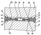
- the two machine components should be one Act cylinder head 10 and an engine block 12, both of which sealing surfaces to be sealed against each other with 10a or 12a were designated. Is between these two sealing surfaces a cylinder head gasket according to the invention, designated as a whole by 14, which in the usual way by means of not shown Screw the cylinder head between the two sealing surfaces was clamped.
- the cylinder head gasket 14 has a sealing plate 16, which is made up of two outer layers 18 and 20 and one Intermediate layer 22.
- the firm riveting of the two External layers are achieved that the intermediate layer 22 with respect the outer layers fixed, but especially still is centered by being clamped between the two outer layers is, and that already in the not between the built-in seal in both machine components.
- the intermediate layer 22 now has an opening-like one Section 22a, in which the designed as a hollow rivet Rivet 24 lies and which makes it possible in the course of riveting of the two outer layers 18, 20 in the cutout 22a approach each other until they are firmly pressed against each other be, as shown in the drawing.
- the two outer layers are converging in the course of riveting but shaping the outer layers, especially before Assembling the sealing plate 16, preferable to the Outer layers 18, 20 already around the later riveting point give their final shape; this can in particular through a combined stamping and bending process the holes in the outer layers for later attachment the rivets are made.
- each outer layer Rivet 24 fully receiving recess and a rivet enclosing stage 29, and preferably also a rivet 24 surrounding so-called half bead 30; there radially outside the half bead 30 the outer layers 18, 20 over a certain Have a distance from the intermediate layer 22, form the half beads surround the rivet 24 sealing elements with springback properties in the direction perpendicular to the Sealing surfaces 10a and 12a, so that the half beads in such a way seal against the sealing surfaces 10a and 12a that by the half beads the shown in the drawing, in Area of the rivet 24 and its immediate surroundings Cavities to be sealed off from the outside.
- the sealing surface area of the both major surfaces of the seal were designated 40; with these sealing surface areas and the beads 30 is the seal against the sealing surfaces 10a and 12a two machine components, d. H. of the cylinder head 10 and the Engine blocks 12.
- the depth of the "countersink" of the rivet 24 can be determined the depth of the sinking of the rivet to the median plane of the Sealing plate be symmetrical, but also asymmetrical can.
- DE-38 00 467-A discloses not the thoughts to shape the impressions so that they can fully accommodate the rivet so that it does not have the level of the two main surfaces of the sealing plate survives, and those places where the outer layers are riveted together, so that they are selected when installed Seal between open and recessed Areas of the sealing surfaces of the to be sealed against each other Machine components are, but this well-known cylinder head gasket also has a fundamentally different structure: Your sealing plate is located between the two outer layers a plate-shaped holding part of a liquid passage opening encircling, annular elastomers Sealing element, which also with the elastomer plate-shaped holding part is in one piece, and the combustion chamber through openings the sealing plate are each from a corrugated surround the relevant combustion chamber opening Metal ring surrounded, which is between the two outer layers the sealing plate, which is through these metal rings should be kept at such a distance from each other, that even when the cylinder head gasket is installed, the plate-shaped Not holding part of the e
Landscapes
- Engineering & Computer Science (AREA)
- General Engineering & Computer Science (AREA)
- Mechanical Engineering (AREA)
- Gasket Seals (AREA)
Abstract
Description
Claims (17)
- Zwischen zwei Maschinenbauteile einzuspannende Flachdichtung, insbesondere Zylinderkopfdichtung, mit einer mehrlagigen Dichtungsplatte, welche zwischen metallischen Außenlagen mindestens eine Zwischenlage sowie an ihren beiden Hauptoberflächen Abdichtflächenbereiche zum abdichtenden Anliegen gegen die Maschinenbauteile aufweist, wobei mindestens die Außenlagen durch Vernieten mittels wenigstens eines Niets aneinander fixiert sind, dadurch gekennzeichnet, daß der Niet (24) in einem Bereich der Dichtungsplatte (16) angeordnet ist, in dem die Außenseiten der Außenlagen (18, 20) einen um so viel geringeren Abstand voneinander aufweisen als in diesem Bereich benachbarten, Abdichtflächenbereiche (40) bildenden Nachbarbereichen der Dichtungsplatte, daß der Niet nicht über das Niveau der Abdichtflächenbereiche dieser Nachbarbereiche übersteht.
- Flachdichtung nach Anspruch 1, dadurch gekennzeichnet, daß die Zwischenlage (22) oder mindestens eine der Zwischenlagen in dem den Niet (24) aufnehmenden Dichtungsplattenbereich eine eine örtliche Annäherung der Außenlagen aneinander ermöglichende Aussparung (22a) aufweist.
- Flachdichtung nach Anspruch 2, dadurch gekennzeichnet, daß die Aussparung von einem öffnungsartigen Ausschnitt (22a) der Zwischenlage (22) gebildet wird.
- Flachdichtung nach einem oder mehreren der vorstehenden Ansprüche, dadurch gekennzeichnet, daß in dem den Niet (24) aufnehmenden Dichtungsplattenbereich die Außenlagen (28, 20) unmittelbar gegeneinander anliegen.
- Flachdichtung nach einem oder mehreren der vorstehenden Ansprüche, dadurch gekennzeichnet, daß der Niet (24) als insbesondere ösenartiger Hohlniet ausgebildet ist.
- Flachdichtung nach einem oder mehreren der vorstehenden Ansprüche, dadurch gekennzeichnet, daß die Außenlagen (18, 20) in den genannten Nachbarbereichen wenigstens an einer Hauptoberfläche der Dichtungsplatte mit mindestens einem Dichtelement (30) versehen sind, welches den den Niet (24) aufnehmenden Dichtungsplattenbereich umschließt.
- Flachdichtung nach Anspruch 6, dadurch gekennzeichnet, daß die Außenlagen (18, 20) an jeder der beiden Hauptoberflächen der Dichtungsplatte (16) mit mindestens einem solchen Dichtelement (30) versehen sind.
- Flachdichtung nach Anspruch 6 oder 7, dadurch gekennzeichnet, daß das Dichtelement (30) als in einer Außenlage (18, 20) ausgebildete Sicke gestaltet ist.
- Flachdichtung nach Anspruch 8, dadurch gekennzeichnet, daß die Sicke (30) eine im Querschnitt ungefähr stufenförmige Halbsicke ist.
- Flachdichtung nach Anspruch 9, dadurch gekennzeichnet, daß bei nicht eingebauter Dichtung die Außenlagen (18, 20) bezüglich des Niets (24) radial außerhalb der Halbsicke (30) einen Abstand von der Zwischenlage (22) aufweisen.
- Flachdichtung nach einem oder mehreren der vorstehenden Ansprüche, dadurch gekennzeichnet, daß die Außenlagen (18, 20) aus Federstahlblech bestehen.
- Flachdichtung nach einem oder mehreren der vorstehenden Ansprüche, dadurch gekennzeichnet, daß die Zwischenlage (22) eine Metallage ist.
- Flachdichtung nach einem oder mehreren der vorstehenden Ansprüche, dadurch gekennzeichnet, daß alle Lagen (18, 20, 22) der Dichtungsplatte (16) von Metallagen gebildet werden.
- Flachdichtung nach einem oder mehreren der vorstehenden Ansprüche, dadurch gekennzeichnet, daß die Dichtung (14) so gestaltet ist, daß mindestens bei eingebauter Dichtung die den Niet (24) umschließenden Bereiche der Zwischenlage (22) zwischen den Außenlagen (18, 20) gepreßt sind.
- Flachdichtung nach einem oder mehreren der vorstehenden Ansprüche, dadurch gekennzeichnet, daß der Niet (24) von zum abdichtenden Anliegen gegen Dichtflächen (10a, 12a) der Maschinenbauteile (10, 12) vorgesehenen Abdichtflächenbereichen (40) der Dichtungsplatte (16) umschlossen ist.
- Flachdichtung nach Anspruch 15, dadurch gekennzeichnet, daß der Niet (24) an einer solchen Stelle der Dichtungsplatte (16) angeordnet ist, welche bei eingebauter Dichtung zwischen öffnungs- und vertiefungslosen Bereichen der Maschinenbauteile (10, 12) liegt.
- Flachdichtung nach einem oder mehreren der vorstehenden Ansprüche, dadurch gekennzeichnet, daß jede der Außenlagen (18, 20) mit einer den Niet (24) aufnehmenden Vertiefung versehen ist, wobei die beiden Vertiefungen den Niet vollständig aufnehmen.
Applications Claiming Priority (2)
| Application Number | Priority Date | Filing Date | Title |
|---|---|---|---|
| DE19916058 | 1999-04-09 | ||
| DE19916058 | 1999-04-09 |
Publications (2)
| Publication Number | Publication Date |
|---|---|
| EP1043524A1 true EP1043524A1 (de) | 2000-10-11 |
| EP1043524B1 EP1043524B1 (de) | 2002-09-11 |
Family
ID=7904024
Family Applications (1)
| Application Number | Title | Priority Date | Filing Date |
|---|---|---|---|
| EP00107638A Revoked EP1043524B1 (de) | 1999-04-09 | 2000-04-08 | Flachdichtung |
Country Status (2)
| Country | Link |
|---|---|
| EP (1) | EP1043524B1 (de) |
| DE (1) | DE50000468D1 (de) |
Families Citing this family (1)
| Publication number | Priority date | Publication date | Assignee | Title |
|---|---|---|---|---|
| DE202012004983U1 (de) | 2012-05-18 | 2013-05-27 | Reinz-Dichtungs-Gmbh | Metallische Flachdichtung |
Citations (3)
| Publication number | Priority date | Publication date | Assignee | Title |
|---|---|---|---|---|
| GB1431183A (en) * | 1972-09-12 | 1976-04-07 | Engineering Components Ltd | Gaskets |
| GB2097870A (en) * | 1981-05-01 | 1982-11-10 | Nicholson Terence Peter | Improvements relating to gaskets |
| EP0695895A1 (de) * | 1994-08-04 | 1996-02-07 | Nippon Gasket Co., Ltd. | Metallisches Flachdichtung |
-
2000
- 2000-04-08 DE DE50000468T patent/DE50000468D1/de not_active Expired - Lifetime
- 2000-04-08 EP EP00107638A patent/EP1043524B1/de not_active Revoked
Patent Citations (3)
| Publication number | Priority date | Publication date | Assignee | Title |
|---|---|---|---|---|
| GB1431183A (en) * | 1972-09-12 | 1976-04-07 | Engineering Components Ltd | Gaskets |
| GB2097870A (en) * | 1981-05-01 | 1982-11-10 | Nicholson Terence Peter | Improvements relating to gaskets |
| EP0695895A1 (de) * | 1994-08-04 | 1996-02-07 | Nippon Gasket Co., Ltd. | Metallisches Flachdichtung |
Also Published As
| Publication number | Publication date |
|---|---|
| DE50000468D1 (de) | 2002-10-17 |
| EP1043524B1 (de) | 2002-09-11 |
Similar Documents
| Publication | Publication Date | Title |
|---|---|---|
| DE19829656B4 (de) | Metalldichtung | |
| DE69108628T2 (de) | Metalldichtung. | |
| DE60006755T2 (de) | Zylinderkopfdichtung mit einem Gasaustrittbereich | |
| DE19634964B4 (de) | Metalldichtung | |
| DE69527237T2 (de) | Flachdichtung aus Metall-Elastomer-Verbrudwerkstoff | |
| DE202011103420U1 (de) | Hydrauliksystemsteuerplatte | |
| DE3915434A1 (de) | Stahllaminat- bzw. -schichtstoffdichtung mit zugehoerigen wuelsten | |
| DE102008003266A1 (de) | Metalldichtung | |
| DE19637356C1 (de) | Metallische Flachdichtung | |
| DE10324667A1 (de) | Zylinderkopfdichtung | |
| DE102014203102A1 (de) | Plattenwärmetauscher für ein Elektrokraftfahrzeug | |
| EP1043524B1 (de) | Flachdichtung | |
| EP0557918B1 (de) | Flachdichtung für Verbrennungskraftmaschinen | |
| EP2270366B1 (de) | Verbindungsanordnung | |
| DE3225420A1 (de) | Dichtungsanordnung und verfahren zu ihrer herstellung | |
| EP1319861B1 (de) | Lagerung mit einem Gummi-Metalllager für einen Getriebeträger | |
| EP1629223B1 (de) | Verfahren zur herstellung einer flachdichtung sowie flachdichtung | |
| DE112023001119T5 (de) | Dichtungsverbindungskörper und dichtung | |
| DE3242526A1 (de) | Zylinderkopfdichtung fuer verbrennungskraftmaschinen | |
| DE102019203754A1 (de) | Metalldichtung | |
| DE102012214665A1 (de) | Arbeitszylinder, insbesondere Nehmerzylinder eines Ausrücksystems | |
| DE19549596C2 (de) | Zylinderkopfdichtung | |
| DE19523825A1 (de) | Metallische Flachdichtung | |
| EP2138745A1 (de) | Zylinderkopfdichtung | |
| DE10235742B4 (de) | Verfahren zur Erzeugung eines Dichtbereiches an einer Flachdichtung, sowie Flachdichtung |
Legal Events
| Date | Code | Title | Description |
|---|---|---|---|
| PUAI | Public reference made under article 153(3) epc to a published international application that has entered the european phase |
Free format text: ORIGINAL CODE: 0009012 |
|
| AK | Designated contracting states |
Kind code of ref document: A1 Designated state(s): DE FR GB IT |
|
| AX | Request for extension of the european patent |
Free format text: AL;LT;LV;MK;RO;SI |
|
| 17P | Request for examination filed |
Effective date: 20001116 |
|
| RAP1 | Party data changed (applicant data changed or rights of an application transferred) |
Owner name: ELRINGKLINGER AG |
|
| AKX | Designation fees paid |
Free format text: DE FR GB IT |
|
| GRAG | Despatch of communication of intention to grant |
Free format text: ORIGINAL CODE: EPIDOS AGRA |
|
| 17Q | First examination report despatched |
Effective date: 20011207 |
|
| GRAG | Despatch of communication of intention to grant |
Free format text: ORIGINAL CODE: EPIDOS AGRA |
|
| GRAG | Despatch of communication of intention to grant |
Free format text: ORIGINAL CODE: EPIDOS AGRA |
|
| GRAH | Despatch of communication of intention to grant a patent |
Free format text: ORIGINAL CODE: EPIDOS IGRA |
|
| GRAH | Despatch of communication of intention to grant a patent |
Free format text: ORIGINAL CODE: EPIDOS IGRA |
|
| GRAA | (expected) grant |
Free format text: ORIGINAL CODE: 0009210 |
|
| RAP1 | Party data changed (applicant data changed or rights of an application transferred) |
Owner name: ELRINGKLINGER AG |
|
| AK | Designated contracting states |
Kind code of ref document: B1 Designated state(s): DE FR GB IT |
|
| REG | Reference to a national code |
Ref country code: GB Ref legal event code: FG4D Free format text: NOT ENGLISH |
|
| REF | Corresponds to: |
Ref document number: 50000468 Country of ref document: DE Date of ref document: 20021017 |
|
| GBT | Gb: translation of ep patent filed (gb section 77(6)(a)/1977) |
Effective date: 20030113 |
|
| ET | Fr: translation filed | ||
| PLBI | Opposition filed |
Free format text: ORIGINAL CODE: 0009260 |
|
| PLAX | Notice of opposition and request to file observation + time limit sent |
Free format text: ORIGINAL CODE: EPIDOSNOBS2 |
|
| 26 | Opposition filed |
Opponent name: FEDERAL-MOGUL HOLDING DEUTSCHLAND Effective date: 20030605 |
|
| PLBB | Reply of patent proprietor to notice(s) of opposition received |
Free format text: ORIGINAL CODE: EPIDOSNOBS3 |
|
| REG | Reference to a national code |
Ref country code: FR Ref legal event code: TP |
|
| PLBQ | Unpublished change to opponent data |
Free format text: ORIGINAL CODE: EPIDOS OPPO |
|
| PLAB | Opposition data, opponent's data or that of the opponent's representative modified |
Free format text: ORIGINAL CODE: 0009299OPPO |
|
| R26 | Opposition filed (corrected) |
Opponent name: FEDERAL-MOGUL HOLDING DEUTSCHLAND Effective date: 20030605 |
|
| PGFP | Annual fee paid to national office [announced via postgrant information from national office to epo] |
Ref country code: GB Payment date: 20090303 Year of fee payment: 10 |
|
| PGFP | Annual fee paid to national office [announced via postgrant information from national office to epo] |
Ref country code: IT Payment date: 20090324 Year of fee payment: 10 |
|
| PGFP | Annual fee paid to national office [announced via postgrant information from national office to epo] |
Ref country code: FR Payment date: 20100521 Year of fee payment: 11 |
|
| PGFP | Annual fee paid to national office [announced via postgrant information from national office to epo] |
Ref country code: DE Payment date: 20100526 Year of fee payment: 11 |
|
| GBPC | Gb: european patent ceased through non-payment of renewal fee |
Effective date: 20100408 |
|
| RDAF | Communication despatched that patent is revoked |
Free format text: ORIGINAL CODE: EPIDOSNREV1 |
|
| PG25 | Lapsed in a contracting state [announced via postgrant information from national office to epo] |
Ref country code: GB Free format text: LAPSE BECAUSE OF NON-PAYMENT OF DUE FEES Effective date: 20100408 Ref country code: IT Free format text: LAPSE BECAUSE OF NON-PAYMENT OF DUE FEES Effective date: 20100408 |
|
| RDAG | Patent revoked |
Free format text: ORIGINAL CODE: 0009271 |
|
| STAA | Information on the status of an ep patent application or granted ep patent |
Free format text: STATUS: PATENT REVOKED |
|
| 27W | Patent revoked |
Effective date: 20101209 |
|
| REG | Reference to a national code |
Ref country code: DE Ref legal event code: R107 Ref document number: 50000468 Country of ref document: DE Effective date: 20110728 |
|
| REG | Reference to a national code |
Ref country code: DE Ref legal event code: R119 Ref document number: 50000468 Country of ref document: DE Effective date: 20121101 |